EP3315434B2 - System zum zuführen von gegenständen in einer mehrstufigen arbeitsgruppe - Google Patents
System zum zuführen von gegenständen in einer mehrstufigen arbeitsgruppe Download PDFInfo
- Publication number
- EP3315434B2 EP3315434B2 EP17197765.5A EP17197765A EP3315434B2 EP 3315434 B2 EP3315434 B2 EP 3315434B2 EP 17197765 A EP17197765 A EP 17197765A EP 3315434 B2 EP3315434 B2 EP 3315434B2
- Authority
- EP
- European Patent Office
- Prior art keywords
- objects
- conveyor
- entrance
- pickup section
- work group
- Prior art date
- Legal status (The legal status is an assumption and is not a legal conclusion. Google has not performed a legal analysis and makes no representation as to the accuracy of the status listed.)
- Active
Links
- 239000002775 capsule Substances 0.000 claims description 31
- 238000009825 accumulation Methods 0.000 claims description 10
- 238000000034 method Methods 0.000 claims description 10
- 238000003825 pressing Methods 0.000 claims description 5
- 230000005540 biological transmission Effects 0.000 claims description 3
- 238000007664 blowing Methods 0.000 claims description 3
- 238000011144 upstream manufacturing Methods 0.000 claims description 3
- 235000013361 beverage Nutrition 0.000 description 7
- 238000009826 distribution Methods 0.000 description 7
- 238000002360 preparation method Methods 0.000 description 6
- 230000006978 adaptation Effects 0.000 description 2
- 238000005265 energy consumption Methods 0.000 description 2
- 238000012423 maintenance Methods 0.000 description 2
- 239000000463 material Substances 0.000 description 2
- 239000000843 powder Substances 0.000 description 2
- 239000000126 substance Substances 0.000 description 2
- 238000005452 bending Methods 0.000 description 1
- 238000004140 cleaning Methods 0.000 description 1
- 238000005520 cutting process Methods 0.000 description 1
- 230000003247 decreasing effect Effects 0.000 description 1
- 230000001419 dependent effect Effects 0.000 description 1
- 230000000694 effects Effects 0.000 description 1
- 235000013305 food Nutrition 0.000 description 1
- 230000005484 gravity Effects 0.000 description 1
- 238000010438 heat treatment Methods 0.000 description 1
- 238000007689 inspection Methods 0.000 description 1
- 238000009434 installation Methods 0.000 description 1
- 239000007788 liquid Substances 0.000 description 1
- 238000004519 manufacturing process Methods 0.000 description 1
- 238000000465 moulding Methods 0.000 description 1
- 230000000284 resting effect Effects 0.000 description 1
- 239000011265 semifinished product Substances 0.000 description 1
- 238000010186 staining Methods 0.000 description 1
- 230000001360 synchronised effect Effects 0.000 description 1
Images


Classifications
-
- B—PERFORMING OPERATIONS; TRANSPORTING
- B65—CONVEYING; PACKING; STORING; HANDLING THIN OR FILAMENTARY MATERIAL
- B65G—TRANSPORT OR STORAGE DEVICES, e.g. CONVEYORS FOR LOADING OR TIPPING, SHOP CONVEYOR SYSTEMS OR PNEUMATIC TUBE CONVEYORS
- B65G33/00—Screw or rotary spiral conveyors
- B65G33/02—Screw or rotary spiral conveyors for articles
- B65G33/04—Screw or rotary spiral conveyors for articles conveyed between a single screw and guiding means
-
- B—PERFORMING OPERATIONS; TRANSPORTING
- B65—CONVEYING; PACKING; STORING; HANDLING THIN OR FILAMENTARY MATERIAL
- B65B—MACHINES, APPARATUS OR DEVICES FOR, OR METHODS OF, PACKAGING ARTICLES OR MATERIALS; UNPACKING
- B65B35/00—Supplying, feeding, arranging or orientating articles to be packaged
- B65B35/10—Feeding, e.g. conveying, single articles
Definitions
- the present invention generally relates to systems and methods for arranging objects which are substantially identical in shape and have a predetermined orientation, in order to feed such objects in a controlled manner to a working or handling station which simultaneously receives and handles a plurality of such objects in parallel.
- the invention relates to a system for arranging and feeding food capsules, especially beverage preparations (coffee capsules), to a filling machine having a plurality of parallel filling lines with respective entrance points for the empty capsules to be filled (multi-entrance filling machine).
- a system for arranging coffee capsules at a multi-entrance filling machine comprises an orientation device for orienting the empty capsules in the desired orientation (usually with their opening upwards), and a very wide conveyor belt which receives the oriented capsules from the orientation device, and accumulates and conveys them along a number (typically six) of parallel paths, arranged side-by-side, to the filling machine having six entrances for the empty capsules to be filled.
- Each entrance of the filling machine corresponds to one of the six conveying paths defined on the conveyor belt, which arranges the empty capsules in a single row for each entrance of the filling machine, which capsules are accumulated in mutual contact and pushed towards/into the entrance so as to be simultaneously picked up by the filling machine and filled.
- US4960156 describes an apparatus for topping off containers with liquid which forms a closest state of the art for the invention.
- US4960156 discloses a system according to the preamble of claim 1 and a method according to the preamble of claim 11.
- the system for arranging objects at a multi-entrance work group comprises the features of claim 1.
- the screw distributor allows to employ only one conveying path for carrying the objects and feeding, however, a plurality of entrances of the multi-entrance work group.
- the conveyor cost, the complexity of the control unit and the number of sensors for detecting the presence of the objects on the conveyor are thus decreased. Moreover, also the size, weight and energy consumption of the conveyor are reduced.
- a distribution member separate from the conveying channel facilitates the adaptation of the system in case of changes in the position of the entrance points, changes in the number of the entrance points, and changes in the object conveyed and placed.
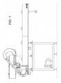
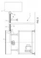
- a system 1 for providing objects 2 at a multi-entrance work group 3 comprises an orientation device 4 for orienting the objects 2 with a desired orientation, as well as a conveyor 5 connected to the orientation device 4 and adapted to receive the objects 2 with the desired orientation from the orientation device 4, and convey the oriented objects 2 in a single row (while maintaining an equal orientation of the oriented objects 2) along a conveying path 6 up to a (final or intermediate) pickup section 7 of the conveying path 6.
- System 1 further comprises a screw distributor 8 arranged at the pickup section 7 of the conveying path 6 and extending along a predetermined number of entrance points 9 of the multi-entrance work group 3.
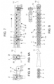
- the screw distributor 8 comprises a helical wall 13 which is shaped and capable of being actuated in rotation so as to engage a predetermined number of objects 2 in sequence from the pickup section 7, and place each of the engaged objects 2 in one of said entrance points 9 of the multi-entrance work group 3, respectively.
- Using a single conveying path in combination with a screw distributor for replenishing objects to a plurality of entrances of the multi-entrance work group reduces the conveyor cost, the complexity of the control unit, and the number of sensors for detecting the presence of the objects on the conveyor. The size, weight and power consumption of the whole system 1 are also reduced.
- a distribution member separate from the conveying channel formed by the conveyor 5 facilitates the adaptation of the system 1 in case of changes in the position of the entrance points 9, changes in the number of the entrance points 9, and changes in the shape of the object 2 conveyed and positioned.
- the helical wall 13 forms a worm screw (with or without central shaft), rotatably supported about an axis of rotation 10 and capable of being rotated about the axis of rotation 10 by means of an electric motor 11, such as a brushless motor, and a transmission 12, preferably a toothed belt transmission.
- an electric motor 11 such as a brushless motor
- a transmission 12 preferably a toothed belt transmission.
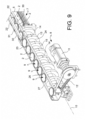
- the helical wall 13 defines a longitudinal pitch, i.e. the free distance between two longitudinally adjacent turns, and a longitudinal thickness 14 of the single turns (shown in figure 9 ) which determine the mutual distance(s) of the objects 2 and the width(s) of the worm screw grooves 16 accommodating the objects 2.
- the predetermined number of objects 2 (six, for example) from the pickup section 7 can thus be easily distributed with high speed (such as 0.45 seconds) and accuracy in the entrance points 9 of the multi-entrance work group 3 by selecting the geometry of the helical wall 13 and the number of turns of the helical wall 13 for each distribution cycle.
- the positioning of the objects 2 is a function of the geometry of the helical wall 13 and of the angular (rotation) position thereof with respect to a reference angular (rotation) position, whereas the number of objects 2 positionable in a corresponding number of entrance points 9 is a function of the number of complete 360° revolutions of the helical wall 13 for each distribution cycle, provided that the total number of turns of the helical wall 13 is sufficient to accommodate the predetermined number of objects 2 during a single distribution cycle.
- the thickness 14 and pitch 15 of the helical wall 13 are substantially constant along the longitudinal extension thereof.
- a front end 17 of the helical wall 13 may be thinned to better fit between two objects 2 accumulated in the pickup section 7 and engage them individually in sequence.
- a guide system 27 is formed along the helical wall 13 (worm screw), adapted to form a constraint against the movements of the objects 2 in the direction transverse to the axis of rotation 10.
- the guide system 27 is configured to maintain the orientation of the objects 2 while they are picked up, one by one, and accommodated individually in the grooves 16 formed by the helical wall 13, and carried to the respective entrance point 9 of the multi-entrance work group by means of the rotation of the helical wall 13.
- the guide system 27 forms an extension of at least some of the guide surfaces of conveyor 5 ( figure 9 ), which will be described below.
- the axis of rotation 10, i.e. the longitudinal axis, of the worm screw formed by the helical wall 13 is at least approximately aligned with or parallel to an accumulation/staking or output direction 18 of the objects 2 in the pickup section 7.
- conveyor 5 is not required to push the single object 2 transversely into the first groove 19 of the helical wall only once it has been cleared (when the previous object has already moved to the next second groove), but the helical wall 13 naturally and continuously screws into the row of objects 2 already arranged in the correct position and with the correct feeding direction. This speeds up the distribution of the objects 2 in the entrance points 9 and prevents the objects 2 from undesirably snapping and bumping against the screw distributor 8.
- the axis of rotation 10, i.e. the longitudinal axis, of the worm screw may be oriented in the direction transverse or oblique to the accumulating or output direction 18 of the pickup section 7.
- the orientation device 4 may comprise an orientation device of rotary or gravitational or different type, widely known in the field.
- rotary orienters are described in EP2883818A1 , for example.
- gravitational orienters are described in WO2015125161A1 , for example.
- Conveyor 5 may comprise a support structure 20 forming a channel 21 extending along the conveying path 6 and adapted to receive a single row of objects 2, and one or more support and sliding surfaces 22 extending along the conveying path 6 and adapted to support the objects 2 in channel 21, where the single objects 2 are hanging/resting in channel 21 with their open end 23 (in case of coffee capsules) facing upwards and with their closed end 24 facing downwards.
- Conveyor 5 comprises a blowing system 25 which directs one or more air flows into channel 21, so as to move the objects 2 in the conveying direction along the conveying path 6 and exert an accumulation thrust thereon, in the pickup section 7, while they are in pressing contact against one another in the aforesaid output direction 18.
- Means for such an accumulation thrust may comprise one or more blowers, one or more mechanical pushers, one or more star wheels, downwards tilted or vertical accumulation sections, etc.
- the support and sliding surfaces 22 may comprise two lateral longitudinal bars 30 extending on two opposite lateral sides of the conveying path 6 and spaced apart so as to provide both a support from underneath for a circumferential edge 26 of the capsule ( figure 9 ).
- the support and sliding surfaces 22 may also comprise a third longitudinal upper bar 31 extending over an upper side of the conveying path 6 and spaced apart from the lateral bars 30 so as to provide a further guide from above and an anti-escape support for the capsule ( figure 9 ).
- the support and sliding surfaces 22 extend into the pickup section 7 at least up to where the screw distributor 8 engages the objects 2 (coffee capsules).
- at least a part of the support and sliding surfaces 22 extend along the helical wall 13 and form the aforesaid guide system 27 of the screw distributor 8.
- the two lateral longitudinal bars 30 extend both along the pickup section 7 and along the helical wall 13, whereas the third longitudinal upper bar 31 extends along the pickup section 7 and ends close to the front end 17 of the helical wall 13, so as to allow the empty coffee capsules arranged in the entrance points 9 to be gripped and lifted upwards by means of the gripping means of the filling machine 3.
- the conveying path 6 may comprise one or more bendings to better fit the space constraints in the installation site.
- the conveying path is substantially horizontal.
- a minimum filling sensor 28 e.g. a photocell
- a minimum filling sensor 28 located upstream of the pickup section 7 or at the pickup section 7 in a position corresponding to a row length sufficient to meet the minimum filling criterion.
- a maximum filling sensor 32 e.g. a photocell
- An electronic control unit 29 of system 1 controls the orientation device 4 as a function of signals from the minimum filling sensor 28 and the maximum filling sensor 32.
- the electronic control unit 29 of system 1 may control the conveyor 5 as a function of signals from the minimum filling sensor 28 and/or the maximum filling sensor 32.
- control unit 29 activates or accelerates the operation of the orientation device 4 in the case of less filling than the preset minimum filling, deactivates or slows down the operation of the orientation device 4 in the case of greater filling than the preset maximum filling, and/or stops or slows down the actuation of the screw distributor 8 in the case of insufficient filling of the pickup section 7.
- the actuation of the orientation device 4 and the conveyor 5 must not necessarily be synchronous with the working cycle of the multi-entrance work group 3, e.g. with the filling cycle of the coffee filling machine, as the objects 2 accumulated in the pickup section 7 and upstream of the pickup section 7 form a buffer of objects 2 to be processed.
- control unit 29 also controls the filling machine or cooperates with a control unit of the filling machine for actuating the screw distributor 8 synchronously with the filling cycle of the filling machine.
- the invention is also directed to a method for arranging objects 2 at a multi-entrance work group 3 according to claim 11.
- the present invention may be particularly advantageously implemented for arranging empty coffee capsules at a multi-entrance coffee filling machine, and possibly filling the capsules with coffee by means of the filling machine. Therefore, the terms "multi-entrance work group” and "object” take, on the one hand, their general meaning, and on the other they indicate a "multi-entrance machine for filling a substance for the preparation of a beverage, especially coffee” and a "capsule for a substance for the preparation of a beverage, especially coffee", respectively.
- multi-entrance work group denotes a general work group adapted and configured to carry out a work with the plurality of objects fed thereto. Such a work may comprise either the handling or processing of objects to modify them or an activity using and combining each of the objects together with another material or another component for manufacturing a more advanced finished or semi-finished product.
- the work performed by the multi-entrance work group may be a deformation, cutting, molding, staining, inspection, heat treatment or cleaning work on the objects.
- the work performed by the multi-entrance work group may be a work of filling the objects with an additional material or combining each of the objects with an additional component or combining a plurality of such objects together.
- the term "entrance point(s)" indicates the position(s) in which the objects are fed into, or made available for, the multi-entrance work group.
- the processing or handling carried out by the multi-entrance work group does not necessarily occur in the entrance points, but it can take place in an innermost part of the multi-entrance work group.
- the multi-entrance work group may be a device for simultaneously filling a plurality of capsules for the preparation of beverages (such as coffee) with a beverage or a beverage powder (such as ground coffee).
- object here denotes a capsule for the preparation of coffee which can be filled with ground coffee powder.
Landscapes
- Engineering & Computer Science (AREA)
- Mechanical Engineering (AREA)
- Attitude Control For Articles On Conveyors (AREA)
- Warehouses Or Storage Devices (AREA)
Claims (12)
- System (1) zum Anordnen von Objekten (2) an einer Arbeitsgruppe (3) mit mehreren Einritten, umfassend:- eine Fördereinrichtung (5), welche dazu eingerichtet ist, die ausgerichteten Objekte (2) in einer einzelnen Reihe entlang einer Förderstrecke (6) hinauf zu einem Aufnahmeabschnitt (7) der Förderstrecke (6) zu fördern,- einen Schraubenverteiler (8), welcher an dem Aufnahmeabschnitt (7) angeordnet ist und sich entlang einer vorbestimmten Anzahl von Eintrittsstellen (9) der Arbeitsgruppe (3) mit mehreren Eintritten ausdehnt, wobei der Schraubenverteiler (8) eine spiralförmige Wand (13) umfasst, welche derart gebildet und drehbetriebsfähig ist, dass sie eine Anzahl der Objekte (2) in Eingriff nimmt, welche der vorbestimmten Anzahl von Eintrittsstellen (9) entspricht, und jedes der in Eingriff genommenen Objekte (2) in jeweils einer der Eintrittsstellen (9) positioniert,dadurch gekennzeichnet, dass das System umfasst:- eine Ausrichtungsvorrichtung (4) zum Ausrichten der Objekte (2) mit einer gewünschten Ausrichtung, und dass- die Fördereinrichtung (5) mit der Ausrichtungsvorrichtung (4) verbunden ist, und dass die Fördereinrichtung (5) umfasst:- eine Halterungsstruktur (20), welche einen Kanal (21) bildet, welcher entlang der Förderstrecke (6) ausgedehnt ist und dazu eingerichtet ist, eine einzelne Reihe von Objekten (2) aufzunehmen, und- eine oder mehrere Halterungs- und Gleitflächen (22), welche entlang der Förderstrecke (6) ausgedehnt sind und dazu eingerichtet sind, die Objekte (2) in dem Kanal (21) zu haltern, wobei die einzelnen Objekte (2) mit einem offenen Ende (23) nach oben weisend und mit einem geschlossenen Ende (24) nach unten weisend in dem Kanal (21) gehaltert sind,- ein Gebläsesystem (25), welches einen oder mehrere Luftströme in einer derartigen Weise in den Kanal leitet, dass es die Objekte (2) entlang der Förderstrecke (6) bewegt und auf diese in dem Aufnahmeabschnitt (7) eine Akkumulationsschubkraft in Druckkontakt gegeneinander in einer Ausgangsrichtung (18) zu der Schraubenfördereinrichtung (8) hin ausübt,das System (1) umfassend:- einen Minimalfüllsensor (28), welcher dem Aufnahmeabschnitt (7) vorgelagert ist oder an dem Aufnahmeabschnitt (7) in einer Position angeordnet ist, welche einer für ein Erfüllen eines Minimalfüllkriteriums ausreichenden Reihenlänge entspricht, um sicherzustellen, dass im Aufnahmeabschnitt (7) eine Reihe mit einer Anzahl von Objekten (2) vorhanden ist, die größer ist als die vorbestimmte Anzahl von Eintrittsstellen (9)- einen Maximalfüllsensor (32), welcher an der Fördereinrichtung (5) in einem Sicherheitsabstand von der Ausgangsstelle der Ausrichtungsvorrichtung (4) angeordnet ist, welcher einem Maximalfüllkriterium entspricht, um zu verhindern, dass sich die Objekte (2) auf dem Förderband (5) bis in die Nähe der Ausgangsstelle der Ausrichtungsvorrichtung (4) stauen,- eine elektronische Steuereinheit (29), die die Ausrichtvorrichtung (4) in Abhängigkeit von den Signalen des Minimalfüllsensors (28) und des Maximalfüllsensors (32) steuert.
- System (1) nach Anspruch 1, wobei die spiralförmige Wand (13) eine Schneckenschraube bildet, welche derart gehaltert ist, dass sie sich um eine Drehachse (10) dreht, und mittels eines Elektromotors (11) und eines Zahnriemengetriebes (12) in Drehung um die Drehachse (10) versetzt wird.
- System (1) nach einem der vorhergehenden Ansprüche, wobei die Dicke (14) und die Steigung (15) der spiralförmigen Wand (13) entlang der longitudinalen Erstreckung davon, mit Ausnahme eines verdünnten vorderen Endes (17), um sich selbst besser zwischen zwei Objekte (2) einsetzen zu können, im Wesentlichen konstant sind.
- System (1) nach einem der vorhergehenden Ansprüche, wobei entlang der spiralförmigen Wand (13) ein Führungssystem (27) gebildet ist, welches Bewegungen der Objekte (2) in wenigstens einer zu der Drehachse (10) der spiralförmigen Wand (13) transversalen Richtung verhindert,
wobei das Führungssystem (27) in einer derartigen Weise konfiguriert ist, dass es die gleiche Ausrichtung wie die Objekte (2) beibehält, während sie individuell in durch die spiralförmige Wand (13) gebildeten Nuten (16) untergebracht sind und jeweils in der jeweiligen Eintrittsstelle (9) getragen sind. - System (1) nach Anspruch 4, wobei das Führungssystem (27) eine Ausdehnung von Führungsflächen der Fördereinrichtung (5) bildet.
- System (1) nach einem der vorhergehenden Ansprüche, wobei die Drehachse (10) der spiralförmigen Wand (13) im Wesentlichen parallel zu einer Akkumulations- und/oder Ausgangsrichtung (18) der Objekte (2) in dem Aufnahmeabschnitt (7) ist.
- System (1) nach einem der vorhergehenden Ansprüche, wobei die Fördereinrichtung (5) Mittel umfasst, welche in dem Aufnahmeabschnitt (7) eine Akkumulationsschubkraft auf die Objekte (2) in Druckkontakt gegeneinander in einer Ausgangsrichtung (18) zu der Schraubenfördereinrichtung (8) hin ausüben.
- System (1) nach einem der vorhergehenden Ansprüche, wobei die Halterungs- und Gleitflächen (22) gebildet sind durch:- zwei laterale longitudinale Stangen (30), welche an zwei entgegengesetzten lateralen Seiten der Förderstrecke (6) ausgedehnt sind und in einer derartigen Weise voneinander beabstandet sind, dass sie beide eine Halterung von unterhalb für einen umlaufenden Rand (26) des Objekts (2) bereitstellen,- eine dritte longitudinale obere Stange (31), welche an einer oberen Seite der Förderstrecke (6) ausgedehnt ist und von den lateralen Stangen (30) derart beabstandet ist, dass sie eine weitere Führung von oberhalb und eine Anti-Flucht-Halterung für das Objekt (2) bereitstellt.
- System (1) nach einem der vorhergehenden Ansprüche, wobei die Förderstrecke (6) im Wesentlichen horizontal ist.
- System (1) nach einem der vorhergehenden Ansprüche, umfassend die Arbeitsgruppe (3) mit mehreren Eintritten, wobei die Objekte (2) Kaffeekapseln sind und die Arbeitsgruppe (3) mit mehreren Eintritten eine Kaffeefüllmaschine ist.
- Verfahren zum Anordnen von Objekten (2) an einer Arbeitsgruppe (3) mit mehreren Eintritten, wobei das Verfahren die folgenden Schritte umfasst:- Ausrichten der Objekte (2) mit einer gewünschten Ausrichtung,- Fördern der Objekte (2) mit der gewünschten Ausrichtung in einer einzelnen Reihe entlang einer Förderstrecke (6) hinauf zu einem Aufnahmeabschnitt (7) der Förderstrecke (6) unter Verwendung einer Fördereinrichtung (5),- Anordnen eines Schnraubenverteilers (8) mit einer spiralförmigen Wand (13) an dem Aufnahmeabschnitt (7) der Förderstrecke (6) und Ausdehnen der spiralförmigen Wand (13) entlang einer vorbestimmten Anzahl von Eintrittsstellen (9) der Arbeitsgruppe (3),- Drehen der spiralförmigen Wand (13), um eine Anzahl von Objekten (2) in Eingriff zu nehmen, welche der vorbestimmten Anzahl von Eintrittsstellen (9) entspricht, und um jedes der in Eingriff genommenen Objekte (2) in einer der Eintrittsstellen (9) zu platzieren,dadurch gekennzeichnet, dass die Fördereinrichtung (5) umfasst:- eine Halterungsstruktur (20), welche einen Kanal (21) bildet, welcher entlang der Förderstrecke (6) ausgedehnt ist und dazu eingerichtet ist, eine einzelne Reihe von Objekten (2) aufzunehmen, und- eine oder mehrere Halterungs- und Gleitflächen (22), welche entlang der Förderstrecke (6) ausgedehnt sind und dazu eingerichtet sind, die Objekte (2) in dem Kanal (21) zu haltern, wobei die einzelnen Objekte (2) mit einem offenen Ende (23) nach oben weisend und mit einem geschlossenen Ende (24) nach unten weisend in dem Kanal (21) gehaltert werden,- ein Gebläsesystem (25), welches einen oder mehrere Luftströme in einer derartigen Weise in den Kanal leitet, dass es die Objekte (2) entlang der Förderstrecke (6) bewegt und auf diese in dem Aufnahmeabschnitt (7) eine Akkumulationsschubkraft in Druckkontakt gegeneinander in einer Ausgangsrichtung (18) zu der Schraubenfördereinrichtung (8) hin ausübt,wobei das Verfahren die Verwendung eines Systems (1) zum Anordnen von Objekten (2) an einer Arbeitsgruppe (3) mit mehreren Eintritten gemäß Anspruch 1 umfasst.
- Verfahren nach Anspruch 11, wobei die Objekte (2) Kaffeekapseln sind und die Arbeitsgruppe (3) mit mehreren Eintritten eine Kaffeefüllmaschine ist.
Applications Claiming Priority (1)
| Application Number | Priority Date | Filing Date | Title |
|---|---|---|---|
| IT102016000109401A IT201600109401A1 (it) | 2016-10-28 | 2016-10-28 | Sistema di predisposizione di oggetti ad un gruppo di lavoro multi-ingresso |
Publications (3)
| Publication Number | Publication Date |
|---|---|
| EP3315434A1 EP3315434A1 (de) | 2018-05-02 |
| EP3315434B1 EP3315434B1 (de) | 2020-08-05 |
| EP3315434B2 true EP3315434B2 (de) | 2023-07-19 |
Family
ID=58228395
Family Applications (1)
| Application Number | Title | Priority Date | Filing Date |
|---|---|---|---|
| EP17197765.5A Active EP3315434B2 (de) | 2016-10-28 | 2017-10-23 | System zum zuführen von gegenständen in einer mehrstufigen arbeitsgruppe |
Country Status (2)
| Country | Link |
|---|---|
| EP (1) | EP3315434B2 (de) |
| IT (1) | IT201600109401A1 (de) |
Families Citing this family (2)
| Publication number | Priority date | Publication date | Assignee | Title |
|---|---|---|---|---|
| CN111299998A (zh) * | 2020-03-11 | 2020-06-19 | 辽宁科技学院 | 一种用于汽车发动机盖锁螺栓的送料机构 |
| DE102021101384C5 (de) * | 2021-01-22 | 2024-04-11 | Syntegon Technology Gmbh | System zum Transport von sterilen schüttfähigen Verschlusselementen |
Family Cites Families (8)
| Publication number | Priority date | Publication date | Assignee | Title |
|---|---|---|---|---|
| FR2454423A1 (fr) * | 1979-04-18 | 1980-11-14 | Remy & Cie E P | Procede de manutention et de repartition automatique de recipients et machine comportant application de ce procede |
| US4960156A (en) * | 1989-01-13 | 1990-10-02 | Howden Food Equipment, Inc. | Method and apparatus for topping off containers with liquid to predetermined headspace level |
| JP2000025930A (ja) * | 1998-07-09 | 2000-01-25 | Fuji Oozx Inc | 振動式パーツフィーダ |
| JP4332929B2 (ja) | 1999-04-07 | 2009-09-16 | 澁谷工業株式会社 | 樹脂ボトルの搬送装置 |
| WO2010131063A1 (en) | 2009-05-15 | 2010-11-18 | Aroma System Srl | Device for equispaced conveying of objects into a packaging machine |
| IT1401254B1 (it) * | 2010-06-14 | 2013-07-18 | Marchesini Group Spa | Macchina per il riempimento e la tappatura di flaconi |
| WO2015037022A1 (en) * | 2013-09-13 | 2015-03-19 | Bonino S.P.A Con Unico Azionista | Electronic control apparatus of an industrial machine |
| DE102014104810A1 (de) * | 2014-04-04 | 2015-10-08 | Groninger GmbH & Co. KG | Vorrichtung und Verfahren zum Überführen von Behältern an eine Behandlungsmaschine |
-
2016
- 2016-10-28 IT IT102016000109401A patent/IT201600109401A1/it unknown
-
2017
- 2017-10-23 EP EP17197765.5A patent/EP3315434B2/de active Active
Also Published As
| Publication number | Publication date |
|---|---|
| EP3315434A1 (de) | 2018-05-02 |
| IT201600109401A1 (it) | 2018-04-28 |
| EP3315434B1 (de) | 2020-08-05 |
Similar Documents
| Publication | Publication Date | Title |
|---|---|---|
| EP3700845B1 (de) | Vorrichtung zum vereinzeln beliebig angeordneter behälter mit voneinander unabhängigen extraktionsmitteln | |
| US9687948B2 (en) | Bar feeder | |
| EP2964551B1 (de) | Vereinzeler | |
| EP0496046A1 (de) | Vorrichtung zum Fördern und Gruppieren von Produkten | |
| KR101565217B1 (ko) | 조미김 가공을 위한 자동화장치 | |
| EP2757045B1 (de) | Vorrichtung zum Greifen und Transportieren von Einzelprodukten | |
| US9290321B2 (en) | Storage section of a conveyor device and method for temporarily storing articles | |
| EP3173361B1 (de) | Transportsystem für verpackungsmaschinen | |
| CN110431095A (zh) | 用于分层堆垛的产品批次的生产 | |
| CN102143901A (zh) | 存储供给设备和用于操作该存储供给设备的方法 | |
| EP3315434B2 (de) | System zum zuführen von gegenständen in einer mehrstufigen arbeitsgruppe | |
| EP2890614B1 (de) | Maschine zum verpacken von in sortierten gruppen angeordneten produkten | |
| US11718484B2 (en) | Method for transversely positioning an article to be transported | |
| CN107108131A (zh) | 可靠地供应符合要求的封闭元件的装置和方法 | |
| US9624038B2 (en) | Device and method for depalletization | |
| EP2554498B1 (de) | Verfahren und vorrichtung zum zuführen von gruppen aus dünnen nahrungsmitteln zu einer verpackungsmaschine | |
| KR101282063B1 (ko) | 포장기용 트레이의 자동이송공급장치 | |
| EP3495104B1 (de) | Vorrichtung zum vereinzeln von lebensmitteln | |
| EP3231742B1 (de) | Vorrichtung und verfahren zur stapelung von artikeln | |
| KR101148180B1 (ko) | 김 이절장치 | |
| US20120067694A1 (en) | Product redistribution apparatus | |
| EP2607276B1 (de) | Vorrichtung und Verfahren zum Zuführen von Papierzuschnitten und ähnlicher flacher Objekte | |
| EP3434631B1 (de) | Vorrichtung zur handhaben und leitung von produkten in einer anlage zur herstellung der besagten produkte und anlage | |
| ES2814103T3 (es) | Dispositivo de colocación con una cinta porcionadora giratoria | |
| US20220097885A1 (en) | Apparatus for grouping products and separating discrete batches, for packaging |
Legal Events
| Date | Code | Title | Description |
|---|---|---|---|
| PUAI | Public reference made under article 153(3) epc to a published international application that has entered the european phase |
Free format text: ORIGINAL CODE: 0009012 |
|
| STAA | Information on the status of an ep patent application or granted ep patent |
Free format text: STATUS: THE APPLICATION HAS BEEN PUBLISHED |
|
| AK | Designated contracting states |
Kind code of ref document: A1 Designated state(s): AL AT BE BG CH CY CZ DE DK EE ES FI FR GB GR HR HU IE IS IT LI LT LU LV MC MK MT NL NO PL PT RO RS SE SI SK SM TR |
|
| AX | Request for extension of the european patent |
Extension state: BA ME |
|
| STAA | Information on the status of an ep patent application or granted ep patent |
Free format text: STATUS: REQUEST FOR EXAMINATION WAS MADE |
|
| 17P | Request for examination filed |
Effective date: 20181011 |
|
| RBV | Designated contracting states (corrected) |
Designated state(s): AL AT BE BG CH CY CZ DE DK EE ES FI FR GB GR HR HU IE IS IT LI LT LU LV MC MK MT NL NO PL PT RO RS SE SI SK SM TR |
|
| STAA | Information on the status of an ep patent application or granted ep patent |
Free format text: STATUS: EXAMINATION IS IN PROGRESS |
|
| 17Q | First examination report despatched |
Effective date: 20191018 |
|
| GRAP | Despatch of communication of intention to grant a patent |
Free format text: ORIGINAL CODE: EPIDOSNIGR1 |
|
| STAA | Information on the status of an ep patent application or granted ep patent |
Free format text: STATUS: GRANT OF PATENT IS INTENDED |
|
| INTG | Intention to grant announced |
Effective date: 20200401 |
|
| GRAS | Grant fee paid |
Free format text: ORIGINAL CODE: EPIDOSNIGR3 |
|
| GRAA | (expected) grant |
Free format text: ORIGINAL CODE: 0009210 |
|
| STAA | Information on the status of an ep patent application or granted ep patent |
Free format text: STATUS: THE PATENT HAS BEEN GRANTED |
|
| AK | Designated contracting states |
Kind code of ref document: B1 Designated state(s): AL AT BE BG CH CY CZ DE DK EE ES FI FR GB GR HR HU IE IS IT LI LT LU LV MC MK MT NL NO PL PT RO RS SE SI SK SM TR |
|
| REG | Reference to a national code |
Ref country code: GB Ref legal event code: FG4D |
|
| REG | Reference to a national code |
Ref country code: CH Ref legal event code: EP |
|
| REG | Reference to a national code |
Ref country code: AT Ref legal event code: REF Ref document number: 1298433 Country of ref document: AT Kind code of ref document: T Effective date: 20200815 |
|
| REG | Reference to a national code |
Ref country code: DE Ref legal event code: R096 Ref document number: 602017020934 Country of ref document: DE |
|
| REG | Reference to a national code |
Ref country code: IE Ref legal event code: FG4D |
|
| REG | Reference to a national code |
Ref country code: CH Ref legal event code: NV Representative=s name: VALIPAT S.A. C/O BOVARD SA NEUCHATEL, CH |
|
| REG | Reference to a national code |
Ref country code: LT Ref legal event code: MG4D |
|
| REG | Reference to a national code |
Ref country code: NL Ref legal event code: MP Effective date: 20200805 |
|
| REG | Reference to a national code |
Ref country code: AT Ref legal event code: MK05 Ref document number: 1298433 Country of ref document: AT Kind code of ref document: T Effective date: 20200805 |
|
| PG25 | Lapsed in a contracting state [announced via postgrant information from national office to epo] |
Ref country code: FI Free format text: LAPSE BECAUSE OF FAILURE TO SUBMIT A TRANSLATION OF THE DESCRIPTION OR TO PAY THE FEE WITHIN THE PRESCRIBED TIME-LIMIT Effective date: 20200805 Ref country code: HR Free format text: LAPSE BECAUSE OF FAILURE TO SUBMIT A TRANSLATION OF THE DESCRIPTION OR TO PAY THE FEE WITHIN THE PRESCRIBED TIME-LIMIT Effective date: 20200805 Ref country code: SE Free format text: LAPSE BECAUSE OF FAILURE TO SUBMIT A TRANSLATION OF THE DESCRIPTION OR TO PAY THE FEE WITHIN THE PRESCRIBED TIME-LIMIT Effective date: 20200805 Ref country code: NO Free format text: LAPSE BECAUSE OF FAILURE TO SUBMIT A TRANSLATION OF THE DESCRIPTION OR TO PAY THE FEE WITHIN THE PRESCRIBED TIME-LIMIT Effective date: 20201105 Ref country code: ES Free format text: LAPSE BECAUSE OF FAILURE TO SUBMIT A TRANSLATION OF THE DESCRIPTION OR TO PAY THE FEE WITHIN THE PRESCRIBED TIME-LIMIT Effective date: 20200805 Ref country code: GR Free format text: LAPSE BECAUSE OF FAILURE TO SUBMIT A TRANSLATION OF THE DESCRIPTION OR TO PAY THE FEE WITHIN THE PRESCRIBED TIME-LIMIT Effective date: 20201106 Ref country code: AT Free format text: LAPSE BECAUSE OF FAILURE TO SUBMIT A TRANSLATION OF THE DESCRIPTION OR TO PAY THE FEE WITHIN THE PRESCRIBED TIME-LIMIT Effective date: 20200805 Ref country code: PT Free format text: LAPSE BECAUSE OF FAILURE TO SUBMIT A TRANSLATION OF THE DESCRIPTION OR TO PAY THE FEE WITHIN THE PRESCRIBED TIME-LIMIT Effective date: 20201207 Ref country code: LT Free format text: LAPSE BECAUSE OF FAILURE TO SUBMIT A TRANSLATION OF THE DESCRIPTION OR TO PAY THE FEE WITHIN THE PRESCRIBED TIME-LIMIT Effective date: 20200805 Ref country code: BG Free format text: LAPSE BECAUSE OF FAILURE TO SUBMIT A TRANSLATION OF THE DESCRIPTION OR TO PAY THE FEE WITHIN THE PRESCRIBED TIME-LIMIT Effective date: 20201105 |
|
| PG25 | Lapsed in a contracting state [announced via postgrant information from national office to epo] |
Ref country code: NL Free format text: LAPSE BECAUSE OF FAILURE TO SUBMIT A TRANSLATION OF THE DESCRIPTION OR TO PAY THE FEE WITHIN THE PRESCRIBED TIME-LIMIT Effective date: 20200805 Ref country code: PL Free format text: LAPSE BECAUSE OF FAILURE TO SUBMIT A TRANSLATION OF THE DESCRIPTION OR TO PAY THE FEE WITHIN THE PRESCRIBED TIME-LIMIT Effective date: 20200805 Ref country code: LV Free format text: LAPSE BECAUSE OF FAILURE TO SUBMIT A TRANSLATION OF THE DESCRIPTION OR TO PAY THE FEE WITHIN THE PRESCRIBED TIME-LIMIT Effective date: 20200805 Ref country code: RS Free format text: LAPSE BECAUSE OF FAILURE TO SUBMIT A TRANSLATION OF THE DESCRIPTION OR TO PAY THE FEE WITHIN THE PRESCRIBED TIME-LIMIT Effective date: 20200805 Ref country code: IS Free format text: LAPSE BECAUSE OF FAILURE TO SUBMIT A TRANSLATION OF THE DESCRIPTION OR TO PAY THE FEE WITHIN THE PRESCRIBED TIME-LIMIT Effective date: 20201205 |
|
| PG25 | Lapsed in a contracting state [announced via postgrant information from national office to epo] |
Ref country code: EE Free format text: LAPSE BECAUSE OF FAILURE TO SUBMIT A TRANSLATION OF THE DESCRIPTION OR TO PAY THE FEE WITHIN THE PRESCRIBED TIME-LIMIT Effective date: 20200805 Ref country code: SM Free format text: LAPSE BECAUSE OF FAILURE TO SUBMIT A TRANSLATION OF THE DESCRIPTION OR TO PAY THE FEE WITHIN THE PRESCRIBED TIME-LIMIT Effective date: 20200805 Ref country code: RO Free format text: LAPSE BECAUSE OF FAILURE TO SUBMIT A TRANSLATION OF THE DESCRIPTION OR TO PAY THE FEE WITHIN THE PRESCRIBED TIME-LIMIT Effective date: 20200805 Ref country code: CZ Free format text: LAPSE BECAUSE OF FAILURE TO SUBMIT A TRANSLATION OF THE DESCRIPTION OR TO PAY THE FEE WITHIN THE PRESCRIBED TIME-LIMIT Effective date: 20200805 Ref country code: DK Free format text: LAPSE BECAUSE OF FAILURE TO SUBMIT A TRANSLATION OF THE DESCRIPTION OR TO PAY THE FEE WITHIN THE PRESCRIBED TIME-LIMIT Effective date: 20200805 |
|
| REG | Reference to a national code |
Ref country code: DE Ref legal event code: R026 Ref document number: 602017020934 Country of ref document: DE |
|
| PLBI | Opposition filed |
Free format text: ORIGINAL CODE: 0009260 |
|
| PLAX | Notice of opposition and request to file observation + time limit sent |
Free format text: ORIGINAL CODE: EPIDOSNOBS2 |
|
| PG25 | Lapsed in a contracting state [announced via postgrant information from national office to epo] |
Ref country code: AL Free format text: LAPSE BECAUSE OF FAILURE TO SUBMIT A TRANSLATION OF THE DESCRIPTION OR TO PAY THE FEE WITHIN THE PRESCRIBED TIME-LIMIT Effective date: 20200805 |
|
| 26 | Opposition filed |
Opponent name: SARG S.R.L. Effective date: 20210504 |
|
| PG25 | Lapsed in a contracting state [announced via postgrant information from national office to epo] |
Ref country code: LU Free format text: LAPSE BECAUSE OF NON-PAYMENT OF DUE FEES Effective date: 20201023 Ref country code: MC Free format text: LAPSE BECAUSE OF FAILURE TO SUBMIT A TRANSLATION OF THE DESCRIPTION OR TO PAY THE FEE WITHIN THE PRESCRIBED TIME-LIMIT Effective date: 20200805 Ref country code: SK Free format text: LAPSE BECAUSE OF FAILURE TO SUBMIT A TRANSLATION OF THE DESCRIPTION OR TO PAY THE FEE WITHIN THE PRESCRIBED TIME-LIMIT Effective date: 20200805 |
|
| REG | Reference to a national code |
Ref country code: BE Ref legal event code: MM Effective date: 20201031 |
|
| PG25 | Lapsed in a contracting state [announced via postgrant information from national office to epo] |
Ref country code: FR Free format text: LAPSE BECAUSE OF NON-PAYMENT OF DUE FEES Effective date: 20201031 Ref country code: IT Free format text: LAPSE BECAUSE OF FAILURE TO SUBMIT A TRANSLATION OF THE DESCRIPTION OR TO PAY THE FEE WITHIN THE PRESCRIBED TIME-LIMIT Effective date: 20200805 |
|
| PLBB | Reply of patent proprietor to notice(s) of opposition received |
Free format text: ORIGINAL CODE: EPIDOSNOBS3 |
|
| PG25 | Lapsed in a contracting state [announced via postgrant information from national office to epo] |
Ref country code: SI Free format text: LAPSE BECAUSE OF FAILURE TO SUBMIT A TRANSLATION OF THE DESCRIPTION OR TO PAY THE FEE WITHIN THE PRESCRIBED TIME-LIMIT Effective date: 20200805 Ref country code: BE Free format text: LAPSE BECAUSE OF NON-PAYMENT OF DUE FEES Effective date: 20201031 |
|
| PG25 | Lapsed in a contracting state [announced via postgrant information from national office to epo] |
Ref country code: IE Free format text: LAPSE BECAUSE OF NON-PAYMENT OF DUE FEES Effective date: 20201023 |
|
| PG25 | Lapsed in a contracting state [announced via postgrant information from national office to epo] |
Ref country code: TR Free format text: LAPSE BECAUSE OF FAILURE TO SUBMIT A TRANSLATION OF THE DESCRIPTION OR TO PAY THE FEE WITHIN THE PRESCRIBED TIME-LIMIT Effective date: 20200805 Ref country code: MT Free format text: LAPSE BECAUSE OF FAILURE TO SUBMIT A TRANSLATION OF THE DESCRIPTION OR TO PAY THE FEE WITHIN THE PRESCRIBED TIME-LIMIT Effective date: 20200805 Ref country code: CY Free format text: LAPSE BECAUSE OF FAILURE TO SUBMIT A TRANSLATION OF THE DESCRIPTION OR TO PAY THE FEE WITHIN THE PRESCRIBED TIME-LIMIT Effective date: 20200805 |
|
| GBPC | Gb: european patent ceased through non-payment of renewal fee |
Effective date: 20211023 |
|
| PG25 | Lapsed in a contracting state [announced via postgrant information from national office to epo] |
Ref country code: MK Free format text: LAPSE BECAUSE OF FAILURE TO SUBMIT A TRANSLATION OF THE DESCRIPTION OR TO PAY THE FEE WITHIN THE PRESCRIBED TIME-LIMIT Effective date: 20200805 |
|
| PG25 | Lapsed in a contracting state [announced via postgrant information from national office to epo] |
Ref country code: GB Free format text: LAPSE BECAUSE OF NON-PAYMENT OF DUE FEES Effective date: 20211023 |
|
| APAH | Appeal reference modified |
Free format text: ORIGINAL CODE: EPIDOSCREFNO |
|
| APBM | Appeal reference recorded |
Free format text: ORIGINAL CODE: EPIDOSNREFNO |
|
| APBP | Date of receipt of notice of appeal recorded |
Free format text: ORIGINAL CODE: EPIDOSNNOA2O |
|
| REG | Reference to a national code |
Ref country code: DE Ref legal event code: R081 Ref document number: 602017020934 Country of ref document: DE Owner name: BONINO S.R.L., IT Free format text: FORMER OWNER: BONINO S.P.A. CON UNICO AZIONISTA, ALESSANDRIA, IT |
|
| APBU | Appeal procedure closed |
Free format text: ORIGINAL CODE: EPIDOSNNOA9O |
|
| PUAH | Patent maintained in amended form |
Free format text: ORIGINAL CODE: 0009272 |
|
| STAA | Information on the status of an ep patent application or granted ep patent |
Free format text: STATUS: PATENT MAINTAINED AS AMENDED |
|
| P01 | Opt-out of the competence of the unified patent court (upc) registered |
Effective date: 20230515 |
|
| RAP4 | Party data changed (patent owner data changed or rights of a patent transferred) |
Owner name: BONINO S.R.L. |
|
| 27A | Patent maintained in amended form |
Effective date: 20230719 |
|
| AK | Designated contracting states |
Kind code of ref document: B2 Designated state(s): AL AT BE BG CH CY CZ DE DK EE ES FI FR GB GR HR HU IE IS IT LI LT LU LV MC MK MT NL NO PL PT RO RS SE SI SK SM TR |
|
| REG | Reference to a national code |
Ref country code: DE Ref legal event code: R102 Ref document number: 602017020934 Country of ref document: DE |
|
| PGFP | Annual fee paid to national office [announced via postgrant information from national office to epo] |
Ref country code: DE Payment date: 20241015 Year of fee payment: 8 |
|
| PGFP | Annual fee paid to national office [announced via postgrant information from national office to epo] |
Ref country code: CH Payment date: 20241101 Year of fee payment: 8 |