EP3315453A1 - Contrôleur de treuil comportant un arrêt automatique et systèmes et procédés associés - Google Patents
Contrôleur de treuil comportant un arrêt automatique et systèmes et procédés associés Download PDFInfo
- Publication number
- EP3315453A1 EP3315453A1 EP17198972.6A EP17198972A EP3315453A1 EP 3315453 A1 EP3315453 A1 EP 3315453A1 EP 17198972 A EP17198972 A EP 17198972A EP 3315453 A1 EP3315453 A1 EP 3315453A1
- Authority
- EP
- European Patent Office
- Prior art keywords
- shut
- winch
- timer
- controller
- ground path
- Prior art date
- Legal status (The legal status is an assumption and is not a legal conclusion. Google has not performed a legal analysis and makes no representation as to the accuracy of the status listed.)
- Withdrawn
Links
Images



Classifications
-
- B—PERFORMING OPERATIONS; TRANSPORTING
- B66—HOISTING; LIFTING; HAULING
- B66D—CAPSTANS; WINCHES; TACKLES, e.g. PULLEY BLOCKS; HOISTS
- B66D1/00—Rope, cable, or chain winding mechanisms; Capstans
- B66D1/28—Other constructional details
- B66D1/40—Control devices
- B66D1/48—Control devices automatic
- B66D1/485—Control devices automatic electrical
-
- B—PERFORMING OPERATIONS; TRANSPORTING
- B66—HOISTING; LIFTING; HAULING
- B66D—CAPSTANS; WINCHES; TACKLES, e.g. PULLEY BLOCKS; HOISTS
- B66D1/00—Rope, cable, or chain winding mechanisms; Capstans
- B66D1/02—Driving gear
- B66D1/12—Driving gear incorporating electric motors
-
- B—PERFORMING OPERATIONS; TRANSPORTING
- B66—HOISTING; LIFTING; HAULING
- B66D—CAPSTANS; WINCHES; TACKLES, e.g. PULLEY BLOCKS; HOISTS
- B66D1/00—Rope, cable, or chain winding mechanisms; Capstans
- B66D1/28—Other constructional details
- B66D1/40—Control devices
- B66D1/42—Control devices non-automatic
- B66D1/46—Control devices non-automatic electric
-
- B—PERFORMING OPERATIONS; TRANSPORTING
- B66—HOISTING; LIFTING; HAULING
- B66D—CAPSTANS; WINCHES; TACKLES, e.g. PULLEY BLOCKS; HOISTS
- B66D3/00—Portable or mobile lifting or hauling appliances
- B66D3/006—Power actuated devices operating on ropes, cables, or chains for hauling in a mainly horizontal direction
-
- G—PHYSICS
- G08—SIGNALLING
- G08C—TRANSMISSION SYSTEMS FOR MEASURED VALUES, CONTROL OR SIMILAR SIGNALS
- G08C17/00—Arrangements for transmitting signals characterised by the use of a wireless electrical link
- G08C17/02—Arrangements for transmitting signals characterised by the use of a wireless electrical link using a radio link
-
- H—ELECTRICITY
- H01—ELECTRIC ELEMENTS
- H01H—ELECTRIC SWITCHES; RELAYS; SELECTORS; EMERGENCY PROTECTIVE DEVICES
- H01H43/00—Time or time-programme switches providing a choice of time-intervals for executing one or more switching actions and automatically terminating their operation after the programme is completed
- H01H43/02—Details
- H01H43/04—Means for time setting
-
- B—PERFORMING OPERATIONS; TRANSPORTING
- B66—HOISTING; LIFTING; HAULING
- B66D—CAPSTANS; WINCHES; TACKLES, e.g. PULLEY BLOCKS; HOISTS
- B66D2700/00—Capstans, winches or hoists
- B66D2700/01—Winches, capstans or pivots
- B66D2700/0125—Motor operated winches
- B66D2700/0141—Electrically actuated
Definitions
- the present technology is directed to winches and, more specifically, to winches with wireless remote control capability, and associated systems and methods.
- Winches are typically employed in situations where a vehicle is unable to negotiate an obstacle (e.g., mud or rocks) on its own.
- a winch is typically used to help extract the vehicle and/or to stabilize the vehicle while negotiating steep terrain.
- winching operations can involve heavy loads. Therefore, an operator typically employs a remote control to operate the winch while positioned away from the winch and cable.
- the disclosed winches can include a frame, a cable drum rotatably supported by the frame, a drive motor operatively connected to the cable drum, and a control module positioned adjacent the cable drum.
- the control module can include circuitry to interface with a remote control via one of two modes. In a wireless mode, the control module can communicate wirelessly with a wireless remote control (e.g., a cell phone or dedicated wireless remote). In the wireless mode, the control module's wireless controller continuously scans for signals from a wireless remote control. This can result in a constant battery drain, which after a period of time could discharge a vehicle's battery.
- the present disclosure provides techniques and technology to automatically shut off the control module.
- the control module can include an enable button that turns on the wireless controller module and starts a timer. If an action is not received from the wireless remote control before the timer expires the control module is turned off.
- the control module can communicate with a wired remote control.
- a jumper wire in the wired remote control's connector completes a ground path circuit in the control module to disable the wireless capability of the control module and cause the control module to send a signal to the wireless remote to turn off.
- Disabling the wireless capability of the control module when the wired remote control is connected to the winch prevents conflicting commands from a wireless remote control that may be in the vicinity of the winch.
- the control module is turned off.
- the winch's wireless controller When configured to operate with a wireless winch remote control, the winch's wireless controller is constantly scanning and looking for a signal from the wireless remote control. This can result in a constant battery drain, which after a period of time can discharge a vehicle's battery.
- Conventional wireless-enablable winches include a switch to turn the wireless transceiver/controller on and off. However, the operator must remember to shut the switch off or suffer battery drain.
- the winches with automatic shut-off disclosed herein help prevent battery drain caused by a wireless controller.
- FIG. 1 illustrates a winch 100 having dual mode remote control and automatic shut-off capabilities configured in accordance with some embodiments of the present technology.
- the winch 100 can include a frame or frame assembly 102 that carries a drive motor 106 which powers a cable drum 104.
- the drive motor 106 drives the drum 104 through a gear train assembly 110.
- a clutch mechanism 115 engages and disengages the drum 104 from the gear train assembly 110 to facilitate quickly and easily unwinding the cable from the drum 104.
- An electrical module, such as a winch control module 108 can span across the cable drum 104 and houses control circuitry for the winch 100.
- the control module 108 can include circuitry to selectively interface with a remote control via either one of two modes depending on the circumstances.
- the control module 108 can communicate wirelessly with a wireless remote control, such as a cell phone 200 or a dedicated wireless remote 202.
- the control module 108 can communicate with a wired remote control 300.
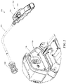
- the wired remote control 300 can include a housing 302 with winch-in and winch-out buttons 304 and 306, respectively.
- the wired remote control 300 can include a cable 308 and a remote connector 310.
- the wired remote control 300 connects to the control module 108 via the remote connector 310 and a mating module connector 118 mounted on the control module 108.
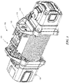
- the control module 108 can include a contactor module 120 and a controller module 122. Accordingly, the contactor module 120 and the controller module 122 can function as sub-modules of the overall, higher level control module 108.
- the contactor module 120 can include a switch that directs vehicle battery current to the drive motor 106 ( FIG. 1 ).
- the contactor module 120 receives signals on low amperage coils from the controller module 122 to switch vehicle battery current to flow in one of two directions (e.g., forward or reverse) to the drive motor 106.
- the controller module 122 can operate in either the wireless mode or the wired mode.
- the controller module 122 can receive a signal from a paired secured transmitter, e.g., the cell phone 200 or wireless remote 202 ( FIG. 1 ), to control the direction of the drive motor 106.
- the controller module 122 can be connected via the connector 118 to the wired remote control 300 ( FIG. 2 ).
- the control module 108 can include an enable switch, such as button 121, that facilitates several functions, including turning on the control module 108 in the wireless mode and pairing a wireless remote control to the controller module 122.
- the enable button 121 is a momentary push button, or other suitable switch, whereby actuation of the button 121 can send different signals to the controller module 122 determined by the duration of the actuation (i.e., how long the button is pushed).
- the remote connector 310 When operating in the wired mode, the connector 118 receives the corresponding remote connector 310 shown in FIG. 2 .
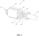
- the remote connector 310 is shown in greater detail in FIG. 4 with the outer housing removed to show the internal components of the connector.
- the remote connector 310 can include a connector body 312 with a plurality of terminal apertures 314 extending therethrough.
- the cable 308 can include three control wires 316, 318, and 320 connected at one end to the winch-in and winch-out buttons 304 and 306 ( FIG. 2 ) and connected at the other end to the connector body 312.
- the control wires 316, 318, and 320 extend into the terminal apertures 314 and connect to corresponding terminals 322.
- the remote connector 310 can also include a jumper wire 324 which functions to disable the wireless mode when the wired remote control 300 is connected to the controller module 122.
- the jumper wire 324 completes a ground path connection on an enable/disable circuit 406 thereby pulling the circuit low.
- Enable switch 121 is also connected to the enable/disable circuit 406. Depending on how long the enable switch 121 is depressed, different functions are activated, as explained more fully below.
- the control wires 316 and 318 connect to the winch-in and winch-out buttons 304 and 306, respectively.
- an over-ride switch 125 can be connected to the controller module 122 that completes a ground path on an over-ride circuit 408. As explained more fully below, the over-ride switch 125 can signal to the controller module 122 to over-ride the automatic shut-off features of the winch.
- the winch-in, winch-out, enable/disable, over-ride circuits 402, 404, 406, and 408 connect to corresponding control pins P13, P14, P15, and P04 on a controller, such as a wireless-enablable microcontroller 400.
- a controller such as a wireless-enablable microcontroller 400.
- the microcontroller 400 registers a low state on pin P13 or pin P14, the microcontroller 400 directs the contactor module 120 ( FIG. 3 ) to switch vehicle battery current to flow in one of two directions (e.g., forward or reverse) to the drive motor 106 ( FIG. 3 ).
- the microcontroller 400 registers a low state on control pin P15, the wireless capability of the microcontroller 400 is disabled.
- the controller can be a wireless-enablable system-on-chip microcontroller, such as microcontroller 400.
- the controller can include separate processor, memory, and/or wireless transceiver modules, for example.
- FIG. 8 illustrates a set of operations 500 for connecting the wired remote control 300 to the winch controller module 122 according to some embodiments.
- the normally open control circuit 406 is closed at operation 504. It should be understood that the control circuit is continuously grounded while the wired remote is plugged in.
- the controller module 122 is turned on at operation 506.
- various lighting i.e., task lighting
- the controller module 122 sends signals to the wireless remote 200/202 to turn off at operation 508.
- the control module also turns off the wireless communication capability of the controller module 122.
- the wired remote 300 is functional at operation 512 to control the winch as described above.
- the control circuit 406 is opened and the controller module 122 is turned off at operation 516.
- FIG. 9 illustrates a set of operations 600 for connecting the wireless remote control 200/202 to the controller module 122 according to some embodiments.
- the normally open control circuit 406 is closed momentarily at operation 604. Accordingly, the normally open enable/disable circuit 406 ( FIG. 5 ) is completed for a non-zero period of time less than a first threshold time period (e.g., five seconds). This signals the controller module 122 to turn on at operation 606.
- the controller module 122 starts a timer (e.g., a shut-off timer) that runs for a preset maximum time (e.g., 3-4 hours).
- a preset maximum time e.g. 3-4 hours.
- the preset maximum time can be at least approximately one hour.
- the timer can be implemented in software and/or hardware. If the timer reaches the maximum time limit at operation 614, the controller module 122 shuts off at operation 618, thereby preventing battery drain. If the user again momentarily presses the enable button 121 at operation 616 for a non-zero period of time less than a second threshold time period (e.g., five seconds), the controller module 122 shuts off at operation 618.
- a second threshold time period e.g., five seconds
- the timer is restarted at operation 608.
- a previously paired wireless remote 200/202 can link to the controller module 122 at any time after power up in order to control the winch.
- the wireless remote 200/202 must have already been paired to the controller module 122 as described below with respect to FIG. 11 .
- the first and second threshold time periods can be the same. In some embodiments, the first and second threshold time periods can be different.
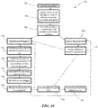
- FIG. 10 illustrates a set of operations 700 for connecting a remote control when the over-ride circuit 408 is closed, in accordance with some embodiments.
- the controller module 122 When the over-ride switch 125 is turned on (i.e., closed) at operation 702 the controller module 122 ( FIG. 3 ) turns on at operation 704. The controller module 122 then blocks communication with the enable button 121 ( FIG. 3 ) and disables the timer from operation 608 ( FIG. 9 ) at operation 706.
- the wireless remote 200/202 can be linked to the controller module at operation 722 and allowed to operate the winch at operation 724 until the wired remote 300 is plugged into the control module 108 at operation 710 or the over-ride switch 125 is turned off at operation 726.
- the wired remote 300 can be plugged in at operation 710 at which point the controller module 122 sends signals to the wireless remote 200/ 202 to turn off at operation 712.
- the controller module 122 also turns off the wireless communication capability of the controller module 122.
- the wired remote 300 is functional at operation 716 to control the winch.
- the control circuit 406 is opened and the controller module 122 turns the wireless capability back on at operation 720.
- the controller module 122 remains on until the over-ride switch 125 is turned off at operation 726 at which point the controller module 122 turns off at operation 728.
- the over-ride switch is useful in situations where a user wants to operate the winch in a conventional manner with direct control of the power supplied to the controller module 122 rather than rely on the automatic shut-off technology described herein.
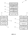
- FIG. 11 illustrates a set of operations 800 for pairing a wireless remote 200/202 to the controller module 122 according to some embodiments.
- a user presses enable button 121 for a long period of time (e.g., greater than five seconds) at operation 802
- the normally open control circuit 406 is closed at operation 804.
- This signals the controller module 122 to enter pairing mode at operation 806.
- the user presses the remote's winch-in and winch-out buttons simultaneously e.g., for at least five seconds at operation 808.
- the wireless remote 200/202 is paired with the controller module 122 at operation 812 and the controller module 122 and the wireless remote 200/202 return to normal operation at operation 814.
- the wireless remote 200/212 flashes an indicator (e.g., a light emitting diode) for five seconds at operation 818. At this point, the user can attempt to pair the wireless remote again at operation 820. If pairing is still unsuccessful, at operation 822 the controller module 122 returns to normal operation after a two minute delay period.
- an indicator e.g., a light emitting diode
- the techniques introduced herein can be embodied as special-purpose hardware (e.g., circuitry), as programmable circuitry appropriately programmed with software and/or firmware, or as a combination of special-purpose and programmable circuitry.
- special-purpose hardware e.g., circuitry
- some embodiments may include a machine-readable medium having stored thereon instructions which may be used to program a computer, a microprocessor, processor, and/or microcontroller (or other electronic devices) to perform a process.
- the machine-readable medium may include, but is not limited to, optical disks, compact disc read-only memories (CD-ROMs), magneto-optical disks, ROMs, random access memories (RAMs), erasable programmable read-only memories (EPROMs), electrically erasable programmable read-only memories (EEPROMs), magnetic or optical cards, flash memory, or other type of media / machine-readable medium suitable for storing electronic instructions.
- a suitable wireless-enablable microcontroller can comprise a Texas Instruments CC1110-CC1111 system-on-chip with low-power RF transceiver.
- winches with automatic shut-off having configurations in accordance with embodiments described herein is that the winch can turn itself off after a preset period of time.
- An advantage of this arrangement is that the winch can automatically shut off to prevent battery drain if a user forgets to otherwise turn off the winch and/or wireless capabilities of the winch.
- the shut-off system can be implemented with relays.
- the system can include a momentary switch in conjunction with a first normally open relay and a second latching relay.
- the two relays are energized.
- the first relay is normally open, and closes when the momentary switch is pushed.
- the microprocessor sends a pass-through signal through the second relay which in turn supplies a voltage signal through a diode to the first normally open relay. This arrangement holds the first relay closed despite the momentary switch being released.
- the microprocessor has an internal timer that is started and runs for a prescribed period of time.
- the microprocessor sends a signal to release its control over the second relay. Once the microprocessor releases control of the second relay and while the momentary switch is not pushed, the first relay opens, thus shutting off power to the microprocessor.
- the relays can be micro-relays mounted on a circuit board of the controller module.
- a representative winch controller with automatic shut-off comprises a winch controller module including a wireless-enablable microcontroller and an enable/disable circuit connected to the microcontroller.
- the winch controller can further include an enable button operative to complete a ground path connection on the enable/disable circuit.
- the microcontroller can further include instructions operative to start a timer when the ground path connection is completed and to turn off the microcontroller if the timer expires prior to receiving a control signal from a wireless remote control linked to the wireless-enablable microcontroller.
- a representative winch with automatic shut-off comprises a frame, a cable drum carried by the frame, a drive motor operatively connected to the cable drum, and a winch control module.
- the control module can include an enable/disable circuit having a normally open ground path connection and a controller having wireless capability connected to the enable/disable circuit.
- the controller includes instructions to start a shut-off timer when the ground path connection is completed for a non-zero period of time less than a preselected momentary time period and reset the shut-off timer when the controller receives a control signal from a wireless remote control prior to the shut-off timer expiring.
- the controller includes instructions to turn off the controller when the shut-off timer expires prior to receiving a control signal from the wireless remote control or when the ground path connection is subsequently completed for a non-zero period of time less than the preselected momentary time period.
- a representative winch with automatic shut-off comprises a frame, a cable drum carried by the frame, a drive motor operatively connected to the cable drum, and a winch control module.
- the winch control module includes an enable/disable circuit having a normally open ground path connection and an over-ride circuit having a normally open ground path connection.
- an enable button can be connected to the enable/disable circuit and operative to complete the ground path connection when actuated.
- a wireless-enablable microcontroller can be connected to the enable/disable circuit and the over-ride circuit.
- the microcontroller can include instructions to start a shut-off timer when the ground path connection of the enable/disable circuit is completed for a non-zero period of time less than a preselected momentary time period and reset the shut-off timer when the microcontroller receives a control signal from a wireless remote control linked to the microcontroller prior to the shut-off timer expiring.
- the controller includes instructions to turn off the microcontroller when the shut-off timer expires prior to receiving a control signal from the wireless remote control or when the ground path connection of the enable/disable circuit is subsequently completed for a non-zero period of time less than the preselected momentary time period.
- the controller includes instructions to disable the shut-off timer while the ground path connection of the over-ride circuit is completed.
- a representative method for automatically shutting-off a winch controller comprises starting a shut-off timer when a normally open ground path connection of an enable/disable circuit is completed for a non-zero period of time less than a preselected momentary time period; resetting the shut-off timer when the winch controller receives a control signal from a wireless remote control prior to the shut-off timer expiring; turning off the winch controller when the shut-off timer expires prior to receiving a control signal from the wireless remote control or when the ground path connection of the enable/disable circuit is subsequently completed for a non-zero period of time less than the preselected momentary time period; and disabling the shut-off timer while a normally open ground path connection of an over-ride circuit is completed.
Landscapes
- Engineering & Computer Science (AREA)
- Mechanical Engineering (AREA)
- Computer Networks & Wireless Communication (AREA)
- Physics & Mathematics (AREA)
- General Physics & Mathematics (AREA)
- Selective Calling Equipment (AREA)
Applications Claiming Priority (2)
| Application Number | Priority Date | Filing Date | Title |
|---|---|---|---|
| US201662414915P | 2016-10-31 | 2016-10-31 | |
| US15/793,544 US20180170726A1 (en) | 2016-10-31 | 2017-10-25 | Winch controller with automatic shut-off, and associated systems and methods |
Publications (1)
| Publication Number | Publication Date |
|---|---|
| EP3315453A1 true EP3315453A1 (fr) | 2018-05-02 |
Family
ID=60191203
Family Applications (1)
| Application Number | Title | Priority Date | Filing Date |
|---|---|---|---|
| EP17198972.6A Withdrawn EP3315453A1 (fr) | 2016-10-31 | 2017-10-27 | Contrôleur de treuil comportant un arrêt automatique et systèmes et procédés associés |
Country Status (4)
| Country | Link |
|---|---|
| US (1) | US20180170726A1 (fr) |
| EP (1) | EP3315453A1 (fr) |
| AU (1) | AU2017251801A1 (fr) |
| CA (1) | CA2984282A1 (fr) |
Families Citing this family (9)
| Publication number | Priority date | Publication date | Assignee | Title |
|---|---|---|---|---|
| US10256580B2 (en) | 2016-10-03 | 2019-04-09 | Superwinch, Llc | Power connectors with integrated fuse supports, and associated systems and methods |
| US20180118531A1 (en) * | 2016-10-06 | 2018-05-03 | Superwinch, Llc | Accessory mounting systems, and methods therefor |
| US10781086B2 (en) | 2016-10-31 | 2020-09-22 | Westin Automotive Products, Inc. | Winches with dual mode remote control, and associated systems and methods |
| US10941538B2 (en) * | 2018-04-13 | 2021-03-09 | Hohhot Sifang Engineering Quality Testing Center | Hammering system with electromagnetic power for dynamic pile testing |
| USD872036S1 (en) * | 2018-10-30 | 2020-01-07 | Polaris Industries Inc. | Winch controller |
| CN111862561B (zh) * | 2019-08-29 | 2024-08-30 | 宁波联达绞盘有限公司 | 一种绞盘遥控电路和遥控设备及其遥控方法 |
| US11377330B2 (en) * | 2020-04-02 | 2022-07-05 | Charles Jackson | Remote controlled lift assembly |
| MX2022008716A (es) * | 2021-07-20 | 2023-01-23 | Polaris Inc | Control de vehiculo automatico. |
| USD985519S1 (en) * | 2021-08-27 | 2023-05-09 | Prowinch, LLC | Control housing |
Citations (3)
| Publication number | Priority date | Publication date | Assignee | Title |
|---|---|---|---|---|
| EP2266915A2 (fr) * | 2009-06-26 | 2010-12-29 | Honeywell International Inc. | Interrupteur de treuil sans fil |
| US7984894B1 (en) * | 2007-06-22 | 2011-07-26 | Chauza Roger N | Electrical clutch engagement/disengagement apparatus |
| US20160046468A1 (en) * | 2014-08-18 | 2016-02-18 | Warn Industries, Inc. | Remote control and user interface for operating a winch |
Family Cites Families (2)
| Publication number | Priority date | Publication date | Assignee | Title |
|---|---|---|---|---|
| EP0113383B1 (fr) * | 1983-01-08 | 1988-06-29 | Friedrich Wilh. Schwing GmbH | Télécommande pour machines à construction, en particulier pour une pompe à béton coopérante avec un bras de distribution |
| US6995682B1 (en) * | 2000-10-30 | 2006-02-07 | Ramsey Winch Company | Wireless remote control for a winch |
-
2017
- 2017-10-25 US US15/793,544 patent/US20180170726A1/en not_active Abandoned
- 2017-10-26 AU AU2017251801A patent/AU2017251801A1/en not_active Abandoned
- 2017-10-27 EP EP17198972.6A patent/EP3315453A1/fr not_active Withdrawn
- 2017-10-30 CA CA2984282A patent/CA2984282A1/fr not_active Abandoned
Patent Citations (3)
| Publication number | Priority date | Publication date | Assignee | Title |
|---|---|---|---|---|
| US7984894B1 (en) * | 2007-06-22 | 2011-07-26 | Chauza Roger N | Electrical clutch engagement/disengagement apparatus |
| EP2266915A2 (fr) * | 2009-06-26 | 2010-12-29 | Honeywell International Inc. | Interrupteur de treuil sans fil |
| US20160046468A1 (en) * | 2014-08-18 | 2016-02-18 | Warn Industries, Inc. | Remote control and user interface for operating a winch |
Also Published As
| Publication number | Publication date |
|---|---|
| CA2984282A1 (fr) | 2018-04-30 |
| US20180170726A1 (en) | 2018-06-21 |
| AU2017251801A1 (en) | 2018-05-17 |
Similar Documents
| Publication | Publication Date | Title |
|---|---|---|
| EP3315453A1 (fr) | Contrôleur de treuil comportant un arrêt automatique et systèmes et procédés associés | |
| US10781086B2 (en) | Winches with dual mode remote control, and associated systems and methods | |
| AU2022202753B2 (en) | Work device | |
| US9592736B2 (en) | Controlling a locking device of an electric charging port | |
| US8978276B2 (en) | Safety systems for wireless control for snow plows | |
| US20130297147A1 (en) | Dark current cutoff system and method for vehicle junction box | |
| KR101508508B1 (ko) | 시동 온오프에 따른 차량용 블랙박스의 선택적 전원공급 장치 및 그 방법 | |
| EP1450227A3 (fr) | Procédé et dispositif pour contrôler automatiquement la trajectoire d'un Véhicule | |
| CA2502885C (fr) | Systeme de demarrage a distance d'un moteur de vehicule a transmission manuelle | |
| AU650551B2 (en) | Vehicle immobilizer with override means | |
| KR101777375B1 (ko) | 블랙박스용 보조 전원 공급장치 | |
| KR20190062986A (ko) | 스위치 점멸 장치 | |
| KR101257024B1 (ko) | 사용자 조작 전원 스위치를 구비한 상시 전원 공급 장치 | |
| CN115503621A (zh) | 智能座舱主机预启动方法及车辆 | |
| CN113936356A (zh) | 一种行车记录仪的控制方法、装置、行车记录仪和介质 | |
| KR20000029218A (ko) | 차량 시동 장치 및 방법 | |
| CN222684149U (zh) | 绞盘装置和具有它的车辆 | |
| KR101508359B1 (ko) | 다기능 차량용 스마트키 | |
| FR2832677A1 (fr) | Dispositif de signalisation lumineuse pour une remorque et procede de mise en place d'un tel dispositif | |
| GB2522036A (en) | Trailer battery charge system | |
| EP4538122A1 (fr) | Dispositif électronique accessoire pour véhicules | |
| JP2026059057A (ja) | 開閉装置制御システム | |
| JP2025144071A (ja) | 開閉装置制御システム及びリモコン | |
| US20160266593A1 (en) | Automatic auxiliary-power detector for pool systems | |
| JP2025027307A (ja) | 開閉装置制御システム及びリモコン |
Legal Events
| Date | Code | Title | Description |
|---|---|---|---|
| PUAI | Public reference made under article 153(3) epc to a published international application that has entered the european phase |
Free format text: ORIGINAL CODE: 0009012 |
|
| AK | Designated contracting states |
Kind code of ref document: A1 Designated state(s): AL AT BE BG CH CY CZ DE DK EE ES FI FR GB GR HR HU IE IS IT LI LT LU LV MC MK MT NL NO PL PT RO RS SE SI SK SM TR |
|
| AX | Request for extension of the european patent |
Extension state: BA ME |
|
| STAA | Information on the status of an ep patent application or granted ep patent |
Free format text: STATUS: THE APPLICATION IS DEEMED TO BE WITHDRAWN |
|
| 18D | Application deemed to be withdrawn |
Effective date: 20181103 |