EP3315741A1 - Moteur à combustion interne à taux de compression variable et procédé d'apprentissage pour ce dernier - Google Patents
Moteur à combustion interne à taux de compression variable et procédé d'apprentissage pour ce dernier Download PDFInfo
- Publication number
- EP3315741A1 EP3315741A1 EP15896346.2A EP15896346A EP3315741A1 EP 3315741 A1 EP3315741 A1 EP 3315741A1 EP 15896346 A EP15896346 A EP 15896346A EP 3315741 A1 EP3315741 A1 EP 3315741A1
- Authority
- EP
- European Patent Office
- Prior art keywords
- control shaft
- stopper
- compression ratio
- rotational direction
- rotational
- Prior art date
- Legal status (The legal status is an assumption and is not a legal conclusion. Google has not performed a legal analysis and makes no representation as to the accuracy of the status listed.)
- Granted
Links
- 230000006835 compression Effects 0.000 title claims abstract description 76
- 238000007906 compression Methods 0.000 title claims abstract description 76
- 238000002485 combustion reaction Methods 0.000 title claims abstract description 19
- 238000000034 method Methods 0.000 title claims 2
- 230000007246 mechanism Effects 0.000 claims abstract description 24
- 238000006243 chemical reaction Methods 0.000 claims abstract description 15
- 230000009467 reduction Effects 0.000 claims description 15
- 230000005540 biological transmission Effects 0.000 claims description 8
- 230000007423 decrease Effects 0.000 claims description 4
- 238000001514 detection method Methods 0.000 description 11
- 239000003638 chemical reducing agent Substances 0.000 description 7
- 230000002542 deteriorative effect Effects 0.000 description 4
- 230000007704 transition Effects 0.000 description 4
- 206010034719 Personality change Diseases 0.000 description 3
- 230000000052 comparative effect Effects 0.000 description 3
- 230000000694 effects Effects 0.000 description 2
- 238000010586 diagram Methods 0.000 description 1
- 230000002708 enhancing effect Effects 0.000 description 1
- 239000000446 fuel Substances 0.000 description 1
- 238000002347 injection Methods 0.000 description 1
- 239000007924 injection Substances 0.000 description 1
- 230000004048 modification Effects 0.000 description 1
- 238000012986 modification Methods 0.000 description 1
- 239000000243 solution Substances 0.000 description 1
- 230000001629 suppression Effects 0.000 description 1
Images



Classifications
-
- F—MECHANICAL ENGINEERING; LIGHTING; HEATING; WEAPONS; BLASTING
- F02—COMBUSTION ENGINES; HOT-GAS OR COMBUSTION-PRODUCT ENGINE PLANTS
- F02B—INTERNAL-COMBUSTION PISTON ENGINES; COMBUSTION ENGINES IN GENERAL
- F02B75/00—Other engines
- F02B75/04—Engines with variable distances between pistons at top dead-centre positions and cylinder heads
- F02B75/045—Engines with variable distances between pistons at top dead-centre positions and cylinder heads by means of a variable connecting rod length
-
- F—MECHANICAL ENGINEERING; LIGHTING; HEATING; WEAPONS; BLASTING
- F02—COMBUSTION ENGINES; HOT-GAS OR COMBUSTION-PRODUCT ENGINE PLANTS
- F02B—INTERNAL-COMBUSTION PISTON ENGINES; COMBUSTION ENGINES IN GENERAL
- F02B75/00—Other engines
- F02B75/32—Engines characterised by connections between pistons and main shafts and not specific to preceding main groups
-
- F—MECHANICAL ENGINEERING; LIGHTING; HEATING; WEAPONS; BLASTING
- F02—COMBUSTION ENGINES; HOT-GAS OR COMBUSTION-PRODUCT ENGINE PLANTS
- F02D—CONTROLLING COMBUSTION ENGINES
- F02D15/00—Varying compression ratio
- F02D15/02—Varying compression ratio by alteration or displacement of piston stroke
Definitions
- the present invention relates to an internal combustion engine equipped with a variable compression ratio mechanism, and specifically to learning of a reference position of a control shaft.
- Patent document 1 discloses a technology in which a reference position of a control shaft is learned in a variable compression ratio internal combustion engine equipped with a variable compression ratio mechanism capable of changing an engine compression ratio in accordance with a rotational position of the control shaft. Concretely, the reference position is learned based on an output signal from a compression ratio sensor in a state where a movable part, which operates in conjunction with the control shaft, has been kept in abutted-engagement with a stopper provided on a crankshaft bearing part that rotatably supports a crankshaft.
- Patent document 2 discloses the detection of a reference position of a control shaft angle in a variable compression ratio internal combustion engine equipped with a variable compression ratio mechanism capable of changing an engine compression ratio in accordance with a rotational position of a first control shaft, while a portion of a second control shaft has been kept in abutted-engagement with a stopper provided on a housing.
- the housing, on which the stopper is provided is located outside of a cylinder block, and thus many link parts intervene between the stopper and a piston. This leads to the reference position accuracy problem such as a deteriorated reference position learning accuracy.
- an object of the present invention to shorten the time duration required for reference position learning without deteriorating the reference position learning accuracy.
- a variable compression ratio internal combustion engine has a variable compression ratio mechanism capable of changing an engine compression ratio in accordance with a rotational position of a control shaft, a drive motor for changing and holding the rotational position of the control shaft, a first stopper provided outside of an engine body for mechanically restricting a position of maximum rotation of the control shaft in a first rotational direction by bringing a first movable part, which operates in conjunction with the control shaft, into abutted-engagement with the first stopper, and a second stopper provided inside of the engine body for mechanically restricting a position of maximum rotation of the control shaft in a second rotational direction opposite to the first rotational direction by bringing a second movable part, which operates in conjunction with the control shaft, into abutted-engagement with the second stopper.
- a reference position of the control shaft is learned in a state where the position of maximum rotation of the control shaft in the first rotational direction has been mechanically restricted by the first stopper. Subsequently, a maximum conversion angle range of the control shaft is learned in a state where the position of maximum rotation of the control shaft in the second rotational direction has been mechanically restricted by the second stopper.
- the first stopper By virtue of the provision of the first stopper outside of the engine body, it is less restriction on the layout in comparison with such a case where the first stopper is provided inside of the engine body. Hence, it is easy to ensure the sufficient strength and rigidity. Therefore, it is possible to strongly and firmly provide the first stopper. Accordingly, it is unnecessary to slow down a speed of the first movable part for limiting a torque when the first movable part of the control shaft is brought into abutted-engagement with the first stopper. As a result of this, it is possible to shorten the time duration required for reference position learning without deteriorating the reference position learning accuracy.
- the maximum conversion angle range of the control shaft is learned in a state where the position of maximum rotation of the control shaft in the second rotational direction has been mechanically restricted by the second stopper provided on a side of the second rotational direction opposite to the first rotational direction. Therefore, it is possible to more certainly eliminate individual differences of control shaft sensors manufactured, and consequently to improve the detection accuracy of an engine compression ratio. Additionally, the provision of the second stopper inside of the engine body contributes to fewer link parts intervening between the second stopper and the piston, in comparison with such a case where the second stopper is provided outside of the engine body. Thus, it is possible to improve the reference position learning accuracy.
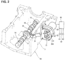
- variable compression ratio mechanism of one embodiment according to the invention, which utilizes a multilink piston-crank mechanism, is hereunder explained in reference to FIGS. 1 and 2 .
- this mechanism itself has been set forth in the previously-discussed Japanese Patent Provisional Publication No. JP2006-226133 and is well-known, and thus it kept to a brief description.
- a variable compression ratio mechanism 10 has a lower link 11, an upper link 12, a control shaft 14, a control eccentric shaft portion 15, and a control link 13.
- the lower link 11 is rotatably installed on a crankpin 5 of crankshaft 4.
- the upper link 12 mechanically links the lower link 11 to the piston 3.
- the control shaft 14 is rotatably supported on the engine body side, such as the cylinder block 1.
- the control link 13 mechanically links the control eccentric shaft portion 15 to the lower link 11.
- the piston 3 and the upper end of upper link 12 are rotatably linked together through a piston pin 16 so as to permit relative rotation between them.
- the lower end of upper link 12 and the lower link 11 are rotatably linked together through a first connecting pin 17 so as to permit relative rotation between them.
- the upper end of control link 13 and the lower link 11 are rotatably linked together through a second connecting pin 18 so as to permit relative rotation between them.
- the lower end of control link 13 is rotatably installed on the control eccentric shaft portion 15.
- a drive motor 20 (see FIG. 2 ) is connected to the control shaft 14 via a connecting mechanism 21.
- An attitude change of lower link 11 occurs by changing and holding a rotational position of control shaft 14 by means of the drive motor 20.
- a piston stroke characteristic including a piston top dead center (TDC) position and a piston bottom dead center (BDC) position changes, and thus an engine compression ratio changes. Therefore, the engine compression ratio can be controlled in accordance with an engine operating condition by driveably controlling the drive motor 20 by means of a control unit 40.
- Control unit 40 is connected to various sensors, such as a control shaft sensor 41, an oil temperature sensor 42, an intake air temperature sensor 43, and the like.
- the control shaft sensor 41 is provided for detecting a rotational position of control shaft 14, corresponding to an engine compression ratio.
- the oil temperature sensor 42 is provided for detecting an oil temperature of the internal combustion engine.
- the intake air temperature sensor 43 is provided for detecting an intake air temperature.
- the control unit is configured to execute, based on output signals from these sensors, various engine controls, such as fuel injection control, ignition timing control, and the like. For instance, based on an output signal from the control shaft sensor 41, the control unit executes feedback control for the drive motor 20 in a manner so as to maintain the engine compression ratio closer to a target compression ratio.
- a housing 22, in which part of the connecting mechanism 21 is housed, is located outside of an intake-side sidewall 7 of an oil-pan upper 6A fixed to the lower section of cylinder block 1 and constructing part of the engine body.
- the housing 22 and the drive motor 20, which is mounted to the housing, are both arranged along the engine longitudinal direction. That is to say, drive motor 20 is mounted onto the cylinder block 1, serving as part of the engine body, via the housing 22.
- the control shaft 14, which is arranged inside of the engine body, and an auxiliary shaft 30 of the connecting mechanism 21, which is arranged inside of the housing 22, are linked together via a lever 31.
- the auxiliary shaft 30 is formed integral with an output shaft of a speed reducer (not shown).
- the auxiliary shaft 30 may be configured separately from the output shaft of the speed reducer, such that the auxiliary shaft and the speed-reducer output shaft integrally rotate with each other.
- lever 31 and the top end of an arm 32 extending radially outward from the axial central portion of control shaft 14 are linked together through a third connecting pin 33 so as to permit relative rotation between them.
- the other end of lever 31 and the auxiliary shaft 30 are linked together through a fourth connecting pin 35 so as to permit relative rotation between them.
- the fourth connecting pin 35 is not shown and omitted, but in lieu thereof a pin connecting hole 35A of auxiliary shaft 30, into which the fourth connecting pin 35 is fitted, is shown.
- a slit-shaped communication hole, through which the lever 31 is inserted, is formed through the intake-side sidewall 7 of oil-pan upper 6A.
- the connecting mechanism 21 is provided with a speed reducer for reducing a power output (a rotational power) outputted from the drive motor 20 and for transmitting the speed-reduced power to the side of control shaft 14.
- a speed reducer for reducing a power output (a rotational power) outputted from the drive motor 20 and for transmitting the speed-reduced power to the side of control shaft 14.
- a specific speed reducer capable of providing high reduction ratios, such as a wave motion gear device or a cycloid planetary-gear speed reducer, is used.
- the connecting mechanism is configured such that a reduction ratio, which is provided by a link structure including the lever 31, the arm 32 and the like, changes in accordance with a rotational position of control shaft 14. That is, the engine compression ratio changes by rotating the control shaft 14, and thus the attitude of the link structure including the arm 32 and the lever 31 changes.
- a reduction ratio of a rotational power transmission path from the drive motor 20 to the control shaft 14 also changes.
- the rotational power transmission path from the drive motor 20 to the control shaft 14 is configured such that the reduction ratio of the rotational power transmission path increases, as the control shaft 14 rotates to a low compression ratio direction.
- the rotational power transmission path is configured such that the reduction ratio increases, as the control shaft 14 rotates to a high compression ratio direction.
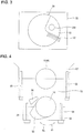
- an axially-extending fan-shaped first movable part 51 is integrally formed with the auxiliary shaft 30, which operates in conjunction with the control shaft 14.
- a first stopper 52 is provided on the housing 22, in which part of the connecting mechanism 21 is housed. The first stopper is provided for mechanically restricting a position of maximum rotation of control shaft 14 in a first rotational direction R1 (see FIG. 4 ) corresponding to the low compression ratio direction by bringing the first movable part 51 into abutted-engagement with the first stopper 52.
- a bearing cap 53 serving as a crankshaft bearing part and an auxiliary cap 54 are fastened together on a bulkhead 57 of cylinder block 1, serving as part of the engine body, with a plurality of bolts 55, 56.
- a main journal portion 4A of crankshaft 4 is rotatably supported between the bearing cap 53 and the bulkhead 57.
- a journal portion of control shaft 14 is rotatably supported between the bearing cap 53 and the auxiliary cap 54.
- a second movable part 58 is provided on the control shaft 14 in a manner so as to extend radially outward from the control shaft. The second movable part 58 integrally operates together with the control shaft 14.
- a second stopper 59 is integrally provided on one side face of bearing cap 53 and configured to extend in the axial direction of control shaft 14 such that the second stopper is abuttable with the second movable part 58.
- the second stopper is provided for mechanically restricting a position of maximum rotation of control shaft 14 in a second rotational direction R2 corresponding to the high compression ratio direction by bringing the second movable part 58 into abutted-engagement with the second stopper 59.
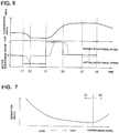
- reference position learning control of the embodiment is explained in detail in reference to FIGS. 5 and 6 .
- the reference position learning control is executed once within an internal combustion engine assembly plant after an internal combustion engine has been assembled. However, such reference position learning control may be executed during operation of the engine, as needed.
- control shaft 14 is rotationally driven in the first rotational direction R1 corresponding to the low compression ratio direction by the drive motor 20.
- the time period t1-t2 from the time t1 to the time t2 in FIG. 6 represents a state where the control shaft 14 is rotating and shifting to the low compression ratio direction.
- the rotational speed of control shaft 14 is not limited, and hence the control shaft 14 is rotationally driven by the drive motor 20 without any torque limit, such that the control shaft 14 rotates at a maximum speed.
- a check is made to determine whether the first movable part 51 has been brought into abutted-engagement with the first stopper 52 and thus the control shaft 14 has been held at the position of maximum rotation in the first rotational direction R1. For instance, the check may be made simply based on information about whether a given period of time has elapsed from the start of driving of the control shaft 14 in the first rotational direction R1. In lieu thereof, the check may be made based on a detection signal of control shaft sensor 41.
- step S12 When it is determined that the first movable part 51 has been brought into abutted-engagement with the first stopper 52 and thus the control shaft 14 has been held at the position of maximum rotation in the first rotational direction R1, the routine proceeds from step S12 to step S13.
- step S13 reference position learning control is executed based on a detection signal of control shaft sensor 41 (see the time period t2-t3 in FIG. 6 ). In this manner, at the specific position at which the rotational position of control shaft 14 has been mechanically restricted by the first stopper 52, the detection signal of control shaft sensor 41 is learned and corrected. Therefore, it is possible to eliminate the individual difference (operating characteristic difference) of the control shaft sensor 41, thereby improving the detection accuracy of an engine compression ratio.
- step S14 the control shaft 14 is rotationally driven in the second rotational direction R2 corresponding to the high compression ratio direction, which is opposite to the first rotational direction R1.
- the rotational speed (target rotational speed) of control shaft 14 is not limited, and hence the control shaft 14 is rotationally driven by the drive motor 20 without any torque limit, such that the control shaft 14 rotates at a maximum speed.
- a check is made to determine whether a speed-switching point (see the time t4 in FIG. 6 ) corresponding to the latter half of the transition period to the high compression ratio has been reached. For instance, the check may be made simply based on information about whether a given period of time has elapsed from the start of the transition period to the high compression ratio. In lieu thereof, the check may be made based on a detection signal of control shaft sensor 41.
- step S15 a driving torque (target rotational speed) of drive motor 20 is limited for the purpose of limiting or restricting the rotational speed of control shaft 14.
- the control shaft 14 rotates in the second rotational direction R2 corresponding to the high speed side.
- step S17 a check is made to determine whether the second movable part 58 has been brought into abutted-engagement with the second stopper 59 and thus the control shaft 14 has been held at the position of maximum rotation in the second rotational direction R2.
- the routine proceeds from step S17 to step S18.
- the first rotational direction R1 is set as a low compression ratio direction
- the second rotational direction R2 is set as a high compression ratio direction
- the first rotational direction R1 may be set as a high compression ratio direction
- the second rotational direction R2 may be set as a low compression ratio direction.
Landscapes
- Engineering & Computer Science (AREA)
- Chemical & Material Sciences (AREA)
- Combustion & Propulsion (AREA)
- Mechanical Engineering (AREA)
- General Engineering & Computer Science (AREA)
- Output Control And Ontrol Of Special Type Engine (AREA)
Applications Claiming Priority (1)
| Application Number | Priority Date | Filing Date | Title |
|---|---|---|---|
| PCT/JP2015/068292 WO2016208024A1 (fr) | 2015-06-25 | 2015-06-25 | Moteur à combustion interne à taux de compression variable et procédé d'apprentissage pour ce dernier |
Publications (3)
| Publication Number | Publication Date |
|---|---|
| EP3315741A1 true EP3315741A1 (fr) | 2018-05-02 |
| EP3315741A4 EP3315741A4 (fr) | 2018-05-16 |
| EP3315741B1 EP3315741B1 (fr) | 2018-10-24 |
Family
ID=57585187
Family Applications (1)
| Application Number | Title | Priority Date | Filing Date |
|---|---|---|---|
| EP15896346.2A Not-in-force EP3315741B1 (fr) | 2015-06-25 | 2015-06-25 | Moteur à combustion interne à taux de compression variable et procédé d'apprentissage pour ce dernier |
Country Status (11)
| Country | Link |
|---|---|
| US (1) | US10337400B2 (fr) |
| EP (1) | EP3315741B1 (fr) |
| JP (1) | JP6372617B2 (fr) |
| KR (1) | KR101849064B1 (fr) |
| CN (1) | CN107709732B (fr) |
| BR (1) | BR112017026447B1 (fr) |
| CA (1) | CA2990708C (fr) |
| MX (1) | MX364035B (fr) |
| MY (1) | MY167719A (fr) |
| RU (1) | RU2670634C9 (fr) |
| WO (1) | WO2016208024A1 (fr) |
Families Citing this family (4)
| Publication number | Priority date | Publication date | Assignee | Title |
|---|---|---|---|---|
| DE102016203133B3 (de) * | 2016-02-26 | 2017-01-26 | Continental Automotive Gmbh | Betriebsverfahren und Brennkraftmaschine |
| CN111173622B (zh) * | 2018-11-12 | 2022-03-25 | 长城汽车股份有限公司 | 可变压缩比机构控制方法 |
| EP3748145B1 (fr) * | 2019-06-07 | 2023-12-06 | Winterthur Gas & Diesel Ltd. | Moteur à taux de compression variable (vcr) |
| CN112576383B (zh) * | 2019-09-29 | 2022-09-30 | 长城汽车股份有限公司 | 可变压缩比发动机的控制方法及装置 |
Family Cites Families (17)
| Publication number | Priority date | Publication date | Assignee | Title |
|---|---|---|---|---|
| RU2144991C1 (ru) * | 1997-10-16 | 2000-01-27 | Ибадуллаев Гаджикадир Алиярович | Двигатель внутреннего сгорания с переменным объемом камер сгорания |
| JP4600074B2 (ja) * | 2005-02-15 | 2010-12-15 | 日産自動車株式会社 | 内燃機関の可変圧縮比装置 |
| EP1965051B1 (fr) * | 2006-09-12 | 2016-01-06 | Honda Motor Co., Ltd. | Ensemble de moteur avec des caractéristiques de course variable |
| JP2009185629A (ja) * | 2008-02-04 | 2009-08-20 | Nissan Motor Co Ltd | 可変圧縮比エンジン |
| JP5136366B2 (ja) | 2008-11-07 | 2013-02-06 | 日産自動車株式会社 | 内燃機関の可変圧縮比機構の制御装置 |
| JP5471560B2 (ja) * | 2010-02-16 | 2014-04-16 | 日産自動車株式会社 | 内燃機関の可変圧縮比装置 |
| JP5668458B2 (ja) | 2010-12-21 | 2015-02-12 | 日産自動車株式会社 | 内燃機関の制御装置 |
| JP5906589B2 (ja) * | 2011-06-01 | 2016-04-20 | 日産自動車株式会社 | 内燃機関の故障診断装置 |
| JP5585540B2 (ja) | 2011-06-14 | 2014-09-10 | トヨタ自動車株式会社 | 内燃機関の制御装置 |
| CN103946515B (zh) * | 2011-11-29 | 2016-10-05 | 日产自动车株式会社 | 可变压缩比内燃机 |
| JP6024221B2 (ja) | 2012-06-06 | 2016-11-09 | 日産自動車株式会社 | 可変圧縮比内燃機関 |
| MX348597B (es) * | 2013-01-09 | 2017-06-21 | Nissan Motor | Dispositivo de accionamiento. |
| RU2530670C1 (ru) * | 2013-06-04 | 2014-10-10 | Ривенер Мусавирович Габдуллин | Двигатель внутреннего сгорания с изменяемой степенью сжатия |
| US20180216520A1 (en) * | 2013-09-02 | 2018-08-02 | Roger John SMITH | An internal combustion engine |
| JP6208035B2 (ja) * | 2014-02-04 | 2017-10-04 | 日立オートモティブシステムズ株式会社 | 内燃機関用リンク機構のアクチュエータと可変圧縮比機構のアクチュエータ |
| JP6208589B2 (ja) * | 2014-02-04 | 2017-10-04 | 日立オートモティブシステムズ株式会社 | 可変圧縮比機構のアクチュエータとリンク機構のアクチュエータ |
| JP6258887B2 (ja) * | 2015-03-05 | 2018-01-10 | 日立オートモティブシステムズ株式会社 | 車両用駆動機構の制御装置及び制御方法 |
-
2015
- 2015-06-25 EP EP15896346.2A patent/EP3315741B1/fr not_active Not-in-force
- 2015-06-25 WO PCT/JP2015/068292 patent/WO2016208024A1/fr not_active Ceased
- 2015-06-25 JP JP2017524514A patent/JP6372617B2/ja not_active Expired - Fee Related
- 2015-06-25 KR KR1020187001948A patent/KR101849064B1/ko not_active Expired - Fee Related
- 2015-06-25 RU RU2018102677A patent/RU2670634C9/ru active
- 2015-06-25 MY MYPI2017704966A patent/MY167719A/en unknown
- 2015-06-25 BR BR112017026447-1A patent/BR112017026447B1/pt not_active IP Right Cessation
- 2015-06-25 US US15/738,897 patent/US10337400B2/en active Active
- 2015-06-25 CA CA2990708A patent/CA2990708C/fr active Active
- 2015-06-25 MX MX2017016229A patent/MX364035B/es active IP Right Grant
- 2015-06-25 CN CN201580081211.5A patent/CN107709732B/zh not_active Expired - Fee Related
Also Published As
| Publication number | Publication date |
|---|---|
| CN107709732A (zh) | 2018-02-16 |
| KR20180014168A (ko) | 2018-02-07 |
| US10337400B2 (en) | 2019-07-02 |
| US20180187594A1 (en) | 2018-07-05 |
| MY167719A (en) | 2018-09-21 |
| JP6372617B2 (ja) | 2018-08-15 |
| EP3315741B1 (fr) | 2018-10-24 |
| BR112017026447B1 (pt) | 2022-02-15 |
| CN107709732B (zh) | 2019-07-23 |
| MX364035B (es) | 2019-04-11 |
| BR112017026447A2 (pt) | 2018-08-14 |
| WO2016208024A1 (fr) | 2016-12-29 |
| CA2990708A1 (fr) | 2016-12-29 |
| RU2670634C1 (ru) | 2018-10-24 |
| MX2017016229A (es) | 2018-04-20 |
| CA2990708C (fr) | 2018-08-14 |
| EP3315741A4 (fr) | 2018-05-16 |
| RU2670634C9 (ru) | 2018-12-04 |
| KR101849064B1 (ko) | 2018-04-13 |
| JPWO2016208024A1 (ja) | 2017-11-02 |
Similar Documents
| Publication | Publication Date | Title |
|---|---|---|
| US8074612B2 (en) | Variable compression ratio apparatus | |
| EP1293659B1 (fr) | Méthode et système de commande pour un moteur à combustion interne | |
| EP1344897A2 (fr) | Dispositif et méthode de commande variable des soupapes utilisent une signal de température pour un moteur à combustion interne | |
| EP3315741B1 (fr) | Moteur à combustion interne à taux de compression variable et procédé d'apprentissage pour ce dernier | |
| EP3267014B1 (fr) | Dispositif et procédé de commande de mécanisme d'entraînement de véhicule | |
| US20090188459A1 (en) | Process and system for starting a direct-injecting internal-combustion engine as well as motor vehicle | |
| JP2007332780A (ja) | 内燃機関の可変動弁装置 | |
| EP3171001B1 (fr) | Moteur à combustion interne à taux de compression variable | |
| US10087856B2 (en) | Control device for internal combustion engine | |
| US9885292B2 (en) | Control device for compression ratio variable internal combustion engine | |
| JP4389555B2 (ja) | 可変圧縮比内燃機関の制御装置 | |
| JP2005069204A (ja) | 可変圧縮比機構付き内燃機関 | |
| US7513228B2 (en) | Internal combustion engine | |
| US9140182B2 (en) | Variable compression ratio control system | |
| CN111173622B (zh) | 可变压缩比机构控制方法 | |
| WO2016067375A1 (fr) | Dispositif de commande pour moteur à combustion interne | |
| JP6354477B2 (ja) | 車両の制御装置 | |
| EP3837436B1 (fr) | Procédé de démarrage de moteur à combustion interne | |
| JP2006307810A (ja) | 内燃機関の制御装置 |
Legal Events
| Date | Code | Title | Description |
|---|---|---|---|
| STAA | Information on the status of an ep patent application or granted ep patent |
Free format text: STATUS: THE INTERNATIONAL PUBLICATION HAS BEEN MADE |
|
| PUAI | Public reference made under article 153(3) epc to a published international application that has entered the european phase |
Free format text: ORIGINAL CODE: 0009012 |
|
| STAA | Information on the status of an ep patent application or granted ep patent |
Free format text: STATUS: REQUEST FOR EXAMINATION WAS MADE |
|
| 17P | Request for examination filed |
Effective date: 20180119 |
|
| AK | Designated contracting states |
Kind code of ref document: A1 Designated state(s): AL AT BE BG CH CY CZ DE DK EE ES FI FR GB GR HR HU IE IS IT LI LT LU LV MC MK MT NL NO PL PT RO RS SE SI SK SM TR |
|
| AX | Request for extension of the european patent |
Extension state: BA ME |
|
| A4 | Supplementary search report drawn up and despatched |
Effective date: 20180416 |
|
| RIC1 | Information provided on ipc code assigned before grant |
Ipc: F02D 15/02 20060101ALI20180410BHEP Ipc: F02B 75/04 20060101AFI20180410BHEP Ipc: F02B 75/32 20060101ALI20180410BHEP |
|
| GRAP | Despatch of communication of intention to grant a patent |
Free format text: ORIGINAL CODE: EPIDOSNIGR1 |
|
| STAA | Information on the status of an ep patent application or granted ep patent |
Free format text: STATUS: GRANT OF PATENT IS INTENDED |
|
| DAX | Request for extension of the european patent (deleted) | ||
| INTG | Intention to grant announced |
Effective date: 20180718 |
|
| GRAS | Grant fee paid |
Free format text: ORIGINAL CODE: EPIDOSNIGR3 |
|
| GRAA | (expected) grant |
Free format text: ORIGINAL CODE: 0009210 |
|
| STAA | Information on the status of an ep patent application or granted ep patent |
Free format text: STATUS: THE PATENT HAS BEEN GRANTED |
|
| DAV | Request for validation of the european patent (deleted) | ||
| AK | Designated contracting states |
Kind code of ref document: B1 Designated state(s): AL AT BE BG CH CY CZ DE DK EE ES FI FR GB GR HR HU IE IS IT LI LT LU LV MC MK MT NL NO PL PT RO RS SE SI SK SM TR |
|
| REG | Reference to a national code |
Ref country code: CH Ref legal event code: EP |
|
| REG | Reference to a national code |
Ref country code: IE Ref legal event code: FG4D |
|
| REG | Reference to a national code |
Ref country code: AT Ref legal event code: REF Ref document number: 1056917 Country of ref document: AT Kind code of ref document: T Effective date: 20181115 |
|
| REG | Reference to a national code |
Ref country code: DE Ref legal event code: R096 Ref document number: 602015018917 Country of ref document: DE |
|
| REG | Reference to a national code |
Ref country code: NL Ref legal event code: MP Effective date: 20181024 |
|
| REG | Reference to a national code |
Ref country code: LT Ref legal event code: MG4D |
|
| REG | Reference to a national code |
Ref country code: AT Ref legal event code: MK05 Ref document number: 1056917 Country of ref document: AT Kind code of ref document: T Effective date: 20181024 |
|
| PG25 | Lapsed in a contracting state [announced via postgrant information from national office to epo] |
Ref country code: NL Free format text: LAPSE BECAUSE OF FAILURE TO SUBMIT A TRANSLATION OF THE DESCRIPTION OR TO PAY THE FEE WITHIN THE PRESCRIBED TIME-LIMIT Effective date: 20181024 |
|
| PG25 | Lapsed in a contracting state [announced via postgrant information from national office to epo] |
Ref country code: FI Free format text: LAPSE BECAUSE OF FAILURE TO SUBMIT A TRANSLATION OF THE DESCRIPTION OR TO PAY THE FEE WITHIN THE PRESCRIBED TIME-LIMIT Effective date: 20181024 Ref country code: IS Free format text: LAPSE BECAUSE OF FAILURE TO SUBMIT A TRANSLATION OF THE DESCRIPTION OR TO PAY THE FEE WITHIN THE PRESCRIBED TIME-LIMIT Effective date: 20190224 Ref country code: NO Free format text: LAPSE BECAUSE OF FAILURE TO SUBMIT A TRANSLATION OF THE DESCRIPTION OR TO PAY THE FEE WITHIN THE PRESCRIBED TIME-LIMIT Effective date: 20190124 Ref country code: AT Free format text: LAPSE BECAUSE OF FAILURE TO SUBMIT A TRANSLATION OF THE DESCRIPTION OR TO PAY THE FEE WITHIN THE PRESCRIBED TIME-LIMIT Effective date: 20181024 Ref country code: LV Free format text: LAPSE BECAUSE OF FAILURE TO SUBMIT A TRANSLATION OF THE DESCRIPTION OR TO PAY THE FEE WITHIN THE PRESCRIBED TIME-LIMIT Effective date: 20181024 Ref country code: LT Free format text: LAPSE BECAUSE OF FAILURE TO SUBMIT A TRANSLATION OF THE DESCRIPTION OR TO PAY THE FEE WITHIN THE PRESCRIBED TIME-LIMIT Effective date: 20181024 Ref country code: ES Free format text: LAPSE BECAUSE OF FAILURE TO SUBMIT A TRANSLATION OF THE DESCRIPTION OR TO PAY THE FEE WITHIN THE PRESCRIBED TIME-LIMIT Effective date: 20181024 Ref country code: BG Free format text: LAPSE BECAUSE OF FAILURE TO SUBMIT A TRANSLATION OF THE DESCRIPTION OR TO PAY THE FEE WITHIN THE PRESCRIBED TIME-LIMIT Effective date: 20190124 Ref country code: HR Free format text: LAPSE BECAUSE OF FAILURE TO SUBMIT A TRANSLATION OF THE DESCRIPTION OR TO PAY THE FEE WITHIN THE PRESCRIBED TIME-LIMIT Effective date: 20181024 Ref country code: PL Free format text: LAPSE BECAUSE OF FAILURE TO SUBMIT A TRANSLATION OF THE DESCRIPTION OR TO PAY THE FEE WITHIN THE PRESCRIBED TIME-LIMIT Effective date: 20181024 |
|
| PG25 | Lapsed in a contracting state [announced via postgrant information from national office to epo] |
Ref country code: PT Free format text: LAPSE BECAUSE OF FAILURE TO SUBMIT A TRANSLATION OF THE DESCRIPTION OR TO PAY THE FEE WITHIN THE PRESCRIBED TIME-LIMIT Effective date: 20190224 Ref country code: AL Free format text: LAPSE BECAUSE OF FAILURE TO SUBMIT A TRANSLATION OF THE DESCRIPTION OR TO PAY THE FEE WITHIN THE PRESCRIBED TIME-LIMIT Effective date: 20181024 Ref country code: SE Free format text: LAPSE BECAUSE OF FAILURE TO SUBMIT A TRANSLATION OF THE DESCRIPTION OR TO PAY THE FEE WITHIN THE PRESCRIBED TIME-LIMIT Effective date: 20181024 Ref country code: GR Free format text: LAPSE BECAUSE OF FAILURE TO SUBMIT A TRANSLATION OF THE DESCRIPTION OR TO PAY THE FEE WITHIN THE PRESCRIBED TIME-LIMIT Effective date: 20190125 Ref country code: RS Free format text: LAPSE BECAUSE OF FAILURE TO SUBMIT A TRANSLATION OF THE DESCRIPTION OR TO PAY THE FEE WITHIN THE PRESCRIBED TIME-LIMIT Effective date: 20181024 |
|
| REG | Reference to a national code |
Ref country code: DE Ref legal event code: R097 Ref document number: 602015018917 Country of ref document: DE |
|
| PG25 | Lapsed in a contracting state [announced via postgrant information from national office to epo] |
Ref country code: IT Free format text: LAPSE BECAUSE OF FAILURE TO SUBMIT A TRANSLATION OF THE DESCRIPTION OR TO PAY THE FEE WITHIN THE PRESCRIBED TIME-LIMIT Effective date: 20181024 Ref country code: CZ Free format text: LAPSE BECAUSE OF FAILURE TO SUBMIT A TRANSLATION OF THE DESCRIPTION OR TO PAY THE FEE WITHIN THE PRESCRIBED TIME-LIMIT Effective date: 20181024 Ref country code: DK Free format text: LAPSE BECAUSE OF FAILURE TO SUBMIT A TRANSLATION OF THE DESCRIPTION OR TO PAY THE FEE WITHIN THE PRESCRIBED TIME-LIMIT Effective date: 20181024 |
|
| PG25 | Lapsed in a contracting state [announced via postgrant information from national office to epo] |
Ref country code: SM Free format text: LAPSE BECAUSE OF FAILURE TO SUBMIT A TRANSLATION OF THE DESCRIPTION OR TO PAY THE FEE WITHIN THE PRESCRIBED TIME-LIMIT Effective date: 20181024 Ref country code: EE Free format text: LAPSE BECAUSE OF FAILURE TO SUBMIT A TRANSLATION OF THE DESCRIPTION OR TO PAY THE FEE WITHIN THE PRESCRIBED TIME-LIMIT Effective date: 20181024 Ref country code: RO Free format text: LAPSE BECAUSE OF FAILURE TO SUBMIT A TRANSLATION OF THE DESCRIPTION OR TO PAY THE FEE WITHIN THE PRESCRIBED TIME-LIMIT Effective date: 20181024 Ref country code: SK Free format text: LAPSE BECAUSE OF FAILURE TO SUBMIT A TRANSLATION OF THE DESCRIPTION OR TO PAY THE FEE WITHIN THE PRESCRIBED TIME-LIMIT Effective date: 20181024 |
|
| PLBE | No opposition filed within time limit |
Free format text: ORIGINAL CODE: 0009261 |
|
| STAA | Information on the status of an ep patent application or granted ep patent |
Free format text: STATUS: NO OPPOSITION FILED WITHIN TIME LIMIT |
|
| 26N | No opposition filed |
Effective date: 20190725 |
|
| PG25 | Lapsed in a contracting state [announced via postgrant information from national office to epo] |
Ref country code: MC Free format text: LAPSE BECAUSE OF FAILURE TO SUBMIT A TRANSLATION OF THE DESCRIPTION OR TO PAY THE FEE WITHIN THE PRESCRIBED TIME-LIMIT Effective date: 20181024 |
|
| REG | Reference to a national code |
Ref country code: CH Ref legal event code: PL |
|
| REG | Reference to a national code |
Ref country code: BE Ref legal event code: MM Effective date: 20190630 |
|
| PG25 | Lapsed in a contracting state [announced via postgrant information from national office to epo] |
Ref country code: TR Free format text: LAPSE BECAUSE OF FAILURE TO SUBMIT A TRANSLATION OF THE DESCRIPTION OR TO PAY THE FEE WITHIN THE PRESCRIBED TIME-LIMIT Effective date: 20181024 |
|
| PG25 | Lapsed in a contracting state [announced via postgrant information from national office to epo] |
Ref country code: IE Free format text: LAPSE BECAUSE OF NON-PAYMENT OF DUE FEES Effective date: 20190625 |
|
| PG25 | Lapsed in a contracting state [announced via postgrant information from national office to epo] |
Ref country code: BE Free format text: LAPSE BECAUSE OF NON-PAYMENT OF DUE FEES Effective date: 20190630 Ref country code: LU Free format text: LAPSE BECAUSE OF NON-PAYMENT OF DUE FEES Effective date: 20190625 Ref country code: LI Free format text: LAPSE BECAUSE OF NON-PAYMENT OF DUE FEES Effective date: 20190630 Ref country code: CH Free format text: LAPSE BECAUSE OF NON-PAYMENT OF DUE FEES Effective date: 20190630 |
|
| PG25 | Lapsed in a contracting state [announced via postgrant information from national office to epo] |
Ref country code: CY Free format text: LAPSE BECAUSE OF FAILURE TO SUBMIT A TRANSLATION OF THE DESCRIPTION OR TO PAY THE FEE WITHIN THE PRESCRIBED TIME-LIMIT Effective date: 20181024 |
|
| PG25 | Lapsed in a contracting state [announced via postgrant information from national office to epo] |
Ref country code: HU Free format text: LAPSE BECAUSE OF FAILURE TO SUBMIT A TRANSLATION OF THE DESCRIPTION OR TO PAY THE FEE WITHIN THE PRESCRIBED TIME-LIMIT; INVALID AB INITIO Effective date: 20150625 Ref country code: MT Free format text: LAPSE BECAUSE OF FAILURE TO SUBMIT A TRANSLATION OF THE DESCRIPTION OR TO PAY THE FEE WITHIN THE PRESCRIBED TIME-LIMIT Effective date: 20181024 |
|
| PG25 | Lapsed in a contracting state [announced via postgrant information from national office to epo] |
Ref country code: SI Free format text: LAPSE BECAUSE OF FAILURE TO SUBMIT A TRANSLATION OF THE DESCRIPTION OR TO PAY THE FEE WITHIN THE PRESCRIBED TIME-LIMIT Effective date: 20181024 |
|
| PG25 | Lapsed in a contracting state [announced via postgrant information from national office to epo] |
Ref country code: MK Free format text: LAPSE BECAUSE OF FAILURE TO SUBMIT A TRANSLATION OF THE DESCRIPTION OR TO PAY THE FEE WITHIN THE PRESCRIBED TIME-LIMIT Effective date: 20181024 |
|
| PGFP | Annual fee paid to national office [announced via postgrant information from national office to epo] |
Ref country code: FR Payment date: 20230523 Year of fee payment: 9 Ref country code: DE Payment date: 20230523 Year of fee payment: 9 |
|
| PGFP | Annual fee paid to national office [announced via postgrant information from national office to epo] |
Ref country code: GB Payment date: 20230523 Year of fee payment: 9 |
|
| REG | Reference to a national code |
Ref country code: DE Ref legal event code: R119 Ref document number: 602015018917 Country of ref document: DE |
|
| GBPC | Gb: european patent ceased through non-payment of renewal fee |
Effective date: 20240625 |
|
| PG25 | Lapsed in a contracting state [announced via postgrant information from national office to epo] |
Ref country code: DE Free format text: LAPSE BECAUSE OF NON-PAYMENT OF DUE FEES Effective date: 20250101 |
|
| PG25 | Lapsed in a contracting state [announced via postgrant information from national office to epo] |
Ref country code: FR Free format text: LAPSE BECAUSE OF NON-PAYMENT OF DUE FEES Effective date: 20240630 |
|
| PG25 | Lapsed in a contracting state [announced via postgrant information from national office to epo] |
Ref country code: GB Free format text: LAPSE BECAUSE OF NON-PAYMENT OF DUE FEES Effective date: 20240625 |