EP3315749A1 - Steuerungsvorrichtung für ein aufladesystem - Google Patents
Steuerungsvorrichtung für ein aufladesystem Download PDFInfo
- Publication number
- EP3315749A1 EP3315749A1 EP15908794.9A EP15908794A EP3315749A1 EP 3315749 A1 EP3315749 A1 EP 3315749A1 EP 15908794 A EP15908794 A EP 15908794A EP 3315749 A1 EP3315749 A1 EP 3315749A1
- Authority
- EP
- European Patent Office
- Prior art keywords
- control
- operational point
- compressor
- current position
- moving direction
- Prior art date
- Legal status (The legal status is an assumption and is not a legal conclusion. Google has not performed a legal analysis and makes no representation as to the accuracy of the status listed.)
- Granted
Links
- 239000000446 fuel Substances 0.000 claims description 18
- 238000002347 injection Methods 0.000 claims description 14
- 239000007924 injection Substances 0.000 claims description 14
- 230000004044 response Effects 0.000 claims description 10
- 230000007246 mechanism Effects 0.000 claims description 9
- 230000008859 change Effects 0.000 claims description 4
- 239000002699 waste material Substances 0.000 claims description 2
- 238000010586 diagram Methods 0.000 description 21
- 238000000034 method Methods 0.000 description 15
- 230000006870 function Effects 0.000 description 11
- 230000008569 process Effects 0.000 description 8
- 238000002485 combustion reaction Methods 0.000 description 7
- 230000000694 effects Effects 0.000 description 2
- 230000001052 transient effect Effects 0.000 description 2
- 230000002159 abnormal effect Effects 0.000 description 1
- 230000006835 compression Effects 0.000 description 1
- 238000007906 compression Methods 0.000 description 1
- 230000008878 coupling Effects 0.000 description 1
- 238000010168 coupling process Methods 0.000 description 1
- 238000005859 coupling reaction Methods 0.000 description 1
- 230000006866 deterioration Effects 0.000 description 1
- 239000000463 material Substances 0.000 description 1
- 238000012986 modification Methods 0.000 description 1
- 230000004048 modification Effects 0.000 description 1
- 239000007787 solid Substances 0.000 description 1
- 239000000243 solution Substances 0.000 description 1
- 238000011144 upstream manufacturing Methods 0.000 description 1
Images


Classifications
-
- F—MECHANICAL ENGINEERING; LIGHTING; HEATING; WEAPONS; BLASTING
- F02—COMBUSTION ENGINES; HOT-GAS OR COMBUSTION-PRODUCT ENGINE PLANTS
- F02D—CONTROLLING COMBUSTION ENGINES
- F02D41/00—Electrical control of supply of combustible mixture or its constituents
- F02D41/0002—Controlling intake air
- F02D41/0007—Controlling intake air for control of turbo-charged or super-charged engines
-
- F—MECHANICAL ENGINEERING; LIGHTING; HEATING; WEAPONS; BLASTING
- F02—COMBUSTION ENGINES; HOT-GAS OR COMBUSTION-PRODUCT ENGINE PLANTS
- F02B—INTERNAL-COMBUSTION PISTON ENGINES; COMBUSTION ENGINES IN GENERAL
- F02B37/00—Engines characterised by provision of pumps driven at least for part of the time by exhaust
- F02B37/12—Control of the pumps
- F02B37/18—Control of the pumps by bypassing exhaust from the inlet to the outlet of turbine or to the atmosphere
-
- F—MECHANICAL ENGINEERING; LIGHTING; HEATING; WEAPONS; BLASTING
- F02—COMBUSTION ENGINES; HOT-GAS OR COMBUSTION-PRODUCT ENGINE PLANTS
- F02B—INTERNAL-COMBUSTION PISTON ENGINES; COMBUSTION ENGINES IN GENERAL
- F02B37/00—Engines characterised by provision of pumps driven at least for part of the time by exhaust
- F02B37/12—Control of the pumps
- F02B37/22—Control of the pumps by varying cross-section of exhaust passages or air passages, e.g. by throttling turbine inlets or outlets or by varying effective number of guide conduits
-
- F—MECHANICAL ENGINEERING; LIGHTING; HEATING; WEAPONS; BLASTING
- F02—COMBUSTION ENGINES; HOT-GAS OR COMBUSTION-PRODUCT ENGINE PLANTS
- F02B—INTERNAL-COMBUSTION PISTON ENGINES; COMBUSTION ENGINES IN GENERAL
- F02B37/00—Engines characterised by provision of pumps driven at least for part of the time by exhaust
- F02B37/12—Control of the pumps
- F02B37/24—Control of the pumps by using pumps or turbines with adjustable guide vanes
-
- F—MECHANICAL ENGINEERING; LIGHTING; HEATING; WEAPONS; BLASTING
- F02—COMBUSTION ENGINES; HOT-GAS OR COMBUSTION-PRODUCT ENGINE PLANTS
- F02D—CONTROLLING COMBUSTION ENGINES
- F02D23/00—Controlling engines characterised by their being supercharged
-
- F—MECHANICAL ENGINEERING; LIGHTING; HEATING; WEAPONS; BLASTING
- F02—COMBUSTION ENGINES; HOT-GAS OR COMBUSTION-PRODUCT ENGINE PLANTS
- F02D—CONTROLLING COMBUSTION ENGINES
- F02D23/00—Controlling engines characterised by their being supercharged
- F02D23/02—Controlling engines characterised by their being supercharged the engines being of fuel-injection type
-
- F—MECHANICAL ENGINEERING; LIGHTING; HEATING; WEAPONS; BLASTING
- F02—COMBUSTION ENGINES; HOT-GAS OR COMBUSTION-PRODUCT ENGINE PLANTS
- F02D—CONTROLLING COMBUSTION ENGINES
- F02D41/00—Electrical control of supply of combustible mixture or its constituents
- F02D41/02—Circuit arrangements for generating control signals
- F02D41/14—Introducing closed-loop corrections
- F02D41/1401—Introducing closed-loop corrections characterised by the control or regulation method
- F02D41/1406—Introducing closed-loop corrections characterised by the control or regulation method with use of a optimisation method, e.g. iteration
-
- F—MECHANICAL ENGINEERING; LIGHTING; HEATING; WEAPONS; BLASTING
- F02—COMBUSTION ENGINES; HOT-GAS OR COMBUSTION-PRODUCT ENGINE PLANTS
- F02D—CONTROLLING COMBUSTION ENGINES
- F02D45/00—Electrical control not provided for in groups F02D41/00 - F02D43/00
-
- F—MECHANICAL ENGINEERING; LIGHTING; HEATING; WEAPONS; BLASTING
- F02—COMBUSTION ENGINES; HOT-GAS OR COMBUSTION-PRODUCT ENGINE PLANTS
- F02B—INTERNAL-COMBUSTION PISTON ENGINES; COMBUSTION ENGINES IN GENERAL
- F02B37/00—Engines characterised by provision of pumps driven at least for part of the time by exhaust
- F02B37/12—Control of the pumps
- F02B2037/122—Control of rotational speed of the pump
-
- F—MECHANICAL ENGINEERING; LIGHTING; HEATING; WEAPONS; BLASTING
- F02—COMBUSTION ENGINES; HOT-GAS OR COMBUSTION-PRODUCT ENGINE PLANTS
- F02B—INTERNAL-COMBUSTION PISTON ENGINES; COMBUSTION ENGINES IN GENERAL
- F02B37/00—Engines characterised by provision of pumps driven at least for part of the time by exhaust
- F02B37/12—Control of the pumps
- F02B2037/125—Control for avoiding pump stall or surge
-
- F—MECHANICAL ENGINEERING; LIGHTING; HEATING; WEAPONS; BLASTING
- F02—COMBUSTION ENGINES; HOT-GAS OR COMBUSTION-PRODUCT ENGINE PLANTS
- F02D—CONTROLLING COMBUSTION ENGINES
- F02D41/00—Electrical control of supply of combustible mixture or its constituents
- F02D41/30—Controlling fuel injection
- F02D41/3005—Details not otherwise provided for
-
- Y—GENERAL TAGGING OF NEW TECHNOLOGICAL DEVELOPMENTS; GENERAL TAGGING OF CROSS-SECTIONAL TECHNOLOGIES SPANNING OVER SEVERAL SECTIONS OF THE IPC; TECHNICAL SUBJECTS COVERED BY FORMER USPC CROSS-REFERENCE ART COLLECTIONS [XRACs] AND DIGESTS
- Y02—TECHNOLOGIES OR APPLICATIONS FOR MITIGATION OR ADAPTATION AGAINST CLIMATE CHANGE
- Y02T—CLIMATE CHANGE MITIGATION TECHNOLOGIES RELATED TO TRANSPORTATION
- Y02T10/00—Road transport of goods or passengers
- Y02T10/10—Internal combustion engine [ICE] based vehicles
- Y02T10/12—Improving ICE efficiencies
Definitions
- the present disclosure relates to a control device for a supercharging system for supplying an engine with compressed intake air.
- a method (supercharging) of compressing intake air with a supercharger and supplying an engine with the compressed intake air is known, and widely used in various engines.
- a supercharger may transiently enter an abnormal operation state called surging.
- surging an abnormal operation state
- a supercharger enters a surging state, it is no longer possible to compress intake air.
- a supercharger enters a surging state often, it may lead to breakage of the devices.
- a supercharger needs to be controlled appropriately so as to avoid entering a surging state as much as possible.
- a feedback control is performed on a supercharger so that an operational point on a compressor map does not enter a surge region, on the basis of information obtained by sensing the intake flow rate and the rotation speed, for instance.
- a supercharger is feedback-controlled on the basis of the current position of an operational point on a compressor map.
- Patent Document 1 discloses performing a feedback control on the turbo rotation speed so that the actual turbo rotation speed detected by a turbo rotation speed sensor matches a target turbo rotation speed corresponding to the current operation state, thereby preventing the operational point of a turbocharger on the compressor map from entering the surge region.
- Patent Document 1 JP2007-291961A
- the operational point of the supercharger may cross the surge line due to failure to control the supercharger on time, and the supercharger may enter a surging state temporarily.
- the pressure ratio output pressure/inlet pressure of a supercharger
- the present invention was made in view of the above, and an object of the present invention is to provide a control apparatus for a supercharging system capable of moving the operational point of the supercharger to a desired position on a compressor map efficiently.
- a control apparatus of a supercharging system for supplying an engine with compressed intake air comprises: a supercharger including a compressor configured to compress the intake air to be supplied to the engine; and a controller for controlling a control device affecting operation of the compressor.
- the controller includes: a compressor map storage part configured to store a compressor map which indicates a relationship of an intake volume flow rate, a pressure ratio, and a compressor rotation speed in the compressor; a current position calculation part configured to calculate a current position of an operational point of the compressor on the compressor map every predetermined period; a moving direction calculation part configured to calculate a moving direction of the operational point on the compressor map on the basis of the current position of the operational point calculated by the current position calculation part; and a control part configured to control the control device on the basis of the current position of the operational point calculated by the current position calculation part and the moving direction of the operational point calculated by the moving direction calculation part.
- Superchargers includes, for example, a turbocharger described below which rotates a compressor with a turbine rotated by exhaust gas discharged from an engine, an electric supercharger which rotates a compressor with kinetic energy from an electric motor, and a mechanical supercharger which rotates a compressor with kinetic energy from a crank shaft of an engine.
- operation of the compressor is controlled on the basis of both of the current position of the operational point and the moving direction of the operational point on the compressor map.
- operation of the compressor is controlled on the basis of only the current position of the operational point on the compressor map, it is possible to use the moving direction of the operational point to control the compressor, and thereby it is possible to move the operational point of the compressor to a desired position on the compressor map efficiently.
- the controller further includes a moving direction determination part configured to determine whether the moving direction of the operational point is in a target direction.
- the control part is configured to control the control device so as to orient the moving direction of the operational point in the target direction, if the moving direction of the operational point is not in the target direction.
- control devices are controlled automatically by the control part so that the moving direction of the operational point turns in the target direction.
- the control part so that the moving direction of the operational point turns in the target direction.
- the controller further includes a control map storage part configured to storage a control map for calculating a control amount of the control device corresponding to the current position of the operational point.
- the control part is configured to correct the control amount of the control device calculated on the basis of the control map, so as to orient the moving direction of the operational point in the target direction.
- the control device is controlled so that the moving direction of the operational point turns in the target direction, by correcting the control amount of the control device calculated on the basis of the control map.
- the control map is, for instance, a map for calculating the control amount of the control devices and the like during normal operation of the engine. Accordingly, it is possible to control the compressor so that the moving direction of the operational point turns in the target direction, with a simple configuration of correcting the control amount calculated by the control map.
- the controller further includes a moving velocity calculation part configured to calculate a moving velocity of the operational point on the basis of a change amount per time of the current position of the operational point calculated by the current position calculation part.
- the control part is configured to control the control device on the basis of the current position of the operational point calculated by the current position calculation part, the moving direction of the operational point calculated by the moving direction calculation part, and the moving velocity of the operational point calculated by the moving velocity calculation part.
- the compressor is controlled on the basis of the moving velocity of the operational point on the compressor map, in addition to the current position of the operational point and the moving direction of the operational point on the compressor map. Accordingly, by using the moving velocity of the operational point to control the compressor, it is possible to reflect the concept of time in the control when moving the operational point of the compressor to a desired position on the compressor map.
- the controller further includes an arrival time estimation part configured to estimate an arrival time the operational point takes to arrive at a predetermined region or a target position from the current position, on the basis of the moving direction and the moving velocity of the operational point.
- the control part is configured to estimate an arrival time the operational point takes to arrive at a predetermined region or a target position from the current position, on the basis of the moving direction and the moving velocity of the operational point, and control the control device in response to a comparison result between a predetermined time and the arrival time estimated by the arrival time estimation part.
- the arrival time the operational point takes to arrive at a predetermined region or a target position from the current potion is estimated on the basis of the moving direction and the moving velocity of the operational point, and the control device is controlled in response to the comparison result between the estimated arrival time and the predetermined time.
- the control device is controlled in response to the comparison result between the estimated arrival time and the predetermined time.
- the predetermined region is a surge region defined as a region where surging is likely to occur if the operational point is in the predetermined region.
- the control part is configured to control the control device so as to avoid entrance of the operational point into the surge region, if the arrival time the operational point takes to arrive at the surge region from the current position is shorter than a first predetermined time.
- the compressor is controlled so as to avoid entrance of the operational point into the surge region if the arrival time the operational point takes to arrive at the surge region over the surge line from the current position is shorter than the first predetermined time.
- the first predetermined time is a time necessary for the operational point at the current position to avoid entering the surge region (response delay time) when a normal feedback control is performed on the control device.
- the arrival time the operational point takes to arrive at the surge region from the current position is longer than the first predetermined time, for instance, if it is possible to avoid entrance of the operational point into the surge region with a normal feedback control, the above described control for avoiding entrance of the supercharger into the surging state is not performed.
- the operational range of the compressor in a normal control state is not unnecessarily narrowed.
- the controller further includes a control map storage part configured to store a control map for calculating a control amount of the control device corresponding to the current position of the operational point.
- the control part is configured to correct the control amount of the control device calculated on the basis of the control map so as to avoid entrance of the operational point into the surge region.
- the control device is controlled so as to avoid entrance of the operational point into the surge region, by correcting the control amount of the control devices calculated on the basis of the control map.
- the control map is, for instance, a map for calculating the control amount of the control device during normal operation of the engine. Accordingly, it is possible to control the compressor so as to avoid entrance of the supercharger into the surging state, with a simple configuration of correcting the control amount calculated by the control map.
- control part is configured to control the control device so that the operational point arrives at the target position in a shorter time than a second predetermined time, if the arrival time the operational point takes to arrive at the target position from the current position is shorter than the second predetermined time.
- the compressor is controlled so that the operational point arrives at the target position in a shorter time than the second predetermined time if the arrival time the operational point takes to arrive at the target position from the current position is shorter than the second predetermined time.
- This target position is a position where the compressor efficiency is higher than a predetermined efficiency on the compressor map (for instance, a position where the compressor efficiency is not less than 75%).
- the controller further includes a control map storage part configured to store a control map for calculating a control amount of the control device corresponding to the current position of the operational point.
- the control part is configured to correct the control amount of the control device calculated on the basis of the control map so that the operational point arrives at the target position in a shorter time than the second predetermined time.
- the control device is controlled so that the operational point arrives at the target position in a shorter time than the second predetermined time, by correcting the control amount of the control device calculated on the basis of the control map.
- the control map is, for instance, a map for calculating the control amount of the control device during normal operation of the engine. Accordingly, it is possible to control the compressor so that the operation point arrives at the target position in a shorter time than the second predetermined time, with a simple configuration of correcting the control amount calculated by the control map.
- the supercharger comprises a turbocharger configured to rotate the compressor with a turbine rotated by exhaust gas discharged from the engine.
- the control device includes at least one of a fuel injection device for supplying the engine with fuel, a variable nozzle mechanism for controlling a flow direction of the exhaust gas flowing into the turbine, or a waste gate valve for controlling a flow rate of the exhaust gas flowing into the turbine.
- a control apparatus for a supercharging system capable of moving the operational point of the supercharger to a desired position on a compressor map accurately. By moving the operational point of the supercharger accurately to a desired position on a compressor map, it is possible to maximize the performance of the supercharger.
- an expression of relative or absolute arrangement such as “in a direction”, “along a direction”, “parallel”, “orthogonal”, “centered”, “concentric” and “coaxial” shall not be construed as indicating only the arrangement in a strict literal sense, but also includes a state where the arrangement is relatively displaced by a tolerance, or by an angle or a distance whereby it is possible to achieve the same function.
- an expression of an equal state such as “same” “equal” and “uniform” shall not be construed as indicating only the state in which the feature is strictly equal, but also includes a state in which there is a tolerance or a difference that can still achieve the same function.
- an expression of a shape such as a rectangular shape or a cylindrical shape shall not be construed as only the geometrically strict shape, but also includes a shape with unevenness or chamfered corners within the range in which the same effect can be achieved.
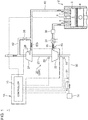
- FIG. 1 is an overall configuration diagram of a supercharging system to which a control apparatus of a supercharging system according to an embodiment of the present invention is to be applied.
- a control apparatus 1A of a supercharging system according to an embodiment of the present invention is a control apparatus 1A of a supercharging system for supplying an engine 2 with compressed intake air IA, and as shown in FIG. 1 , the control apparatus 1A includes a supercharger 20 including a compressor 22 to compress intake air IA to be supplied to the engine 2 and a controller 10 for controlling control devices that affect operation of the compressor 22.
- the supercharger 20 includes a turbocharger 20A to rotate the compressor 22 with a turbine 24 which is rotated by exhaust gas EG discharged from the engine 2.
- the turbocharger 20A includes the compressor 22 disposed in the intake duct 30, a turbine 24 disposed in an exhaust duct 40, and a rotor 23 coupling the compressor 22 and the turbine 24.
- the turbine 24 is rotary-driven by exhaust energy of exhaust gas EG discharged from the engine 2, and the compressor 22 is coaxially driven, thereby compressing the intake air IA having flowed into the compressor 22.
- the intake air IA compressed by the compressor 22 is cooled by an inter cooler 34, having the intake flow rate adjusted by a throttle valve 36, and is supplied to a combustion chamber 8 via an intake port 5.
- the combustion chamber 8 is a space defined between a cylinder liner 3 and a piston 4.
- the engine 2 includes a fuel injection device 6 for injecting a fuel into the combustion chamber 8.
- the fuel supplied to the combustion chamber 8 from the fuel injection device 6 is self-ignited (or ignited by a non-depicted ignition device) by compression heat, and thereby is combusted and expanded in the combustion chamber 8.
- Exhaust gas EG generated in the combustion chamber 8 is discharged to the exhaust duct 40 via an exhaust port 7.
- the exhaust gas exhausted to the exhaust duct 40 flows into the turbine 24 of the above described turbocharger 20A to rotary-drive the turbine 24. Further, a bypass channel 42 bypassing the turbine 24 is connected to the exhaust duct 40. A waste-gate valve 28 is disposed in the bypass channel 42, for controlling the flow rate of exhaust gas EG flowing through the bypass channel 42.
- the turbine 24 is provided with a variable nozzle mechanism 26 for controlling the flow of the exhaust gas EG which acts on the turbine 24.
- the above described devices including the fuel injection device 6, the variable nozzle mechanism 26, and the waste-gate valve 28 correspond to the above described control devices that affect operation of the compressor 22.
- an air flow meter 51 for measuring the flow rate of the intake air IA flowing through the intake duct 30 and an intake temperature sensor 52 for measuring the temperature of intake air flowing through the intake duct 30 are provided on the upstream side of the compressor 22 in the intake duct 30. Furthermore, an inlet pressure sensor 53 for measuring the pressure of intake air IA flowing into the compressor 22 is disposed at an inlet of the compressor 22 in the intake duct 30. Furthermore, an outlet pressure sensor 54 for measuring the pressure of intake air IA compressed by the compressor 22 is disposed at an outlet of the compressor 22 in the intake duct 30. Furthermore, the turbocharger 20 is provided with a turbo rotation speed sensor 55 for measuring the turbo rotation speed (i.e. the rotation speed of the compressor 22). Each information measured by the air flow meter 51, the intake temperature sensor 52, the inlet pressure sensor 53, the outlet pressure sensor 54, and the turbo rotation speed sensor 55 is transmitted to the controller 10.
- the controller 10 comprises a microcomputer separate from one another, the microcomputer including a central processing unit (CPU), a random access memory (RAM), a read only memory (ROM), and an I/O interface.
- CPU central processing unit
- RAM random access memory
- ROM read only memory
- I/O interface I/O interface
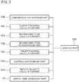
- FIG. 2 is a block diagram for describing the function of a controller.
- the controller 10 includes a control part 10A, a compressor map storage part 10B, a current position calculation part 10C, and a moving direction calculation part 10D.
- the compressor map storage part 10B is a part of the controller 10, which functions as a memory that stores the compressor map M1 described below.
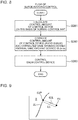
- FIG. 3 is a diagram of a compressor map.
- the horizontal axis represents the corrected flow rate Qa and the vertical axis represents the pressure ratio ⁇ .
- the corrected flow rate Qa is obtained by converting the intake flow rate detected by the air flow meter 51 into an intake volume flow rate at a reference temperature.
- the compressor efficiency ⁇ is represented by the dotted line
- the turbo rotation speed Nt is represented by the chain line.
- the turbo rotation speed Nt can be determined from the turbo rotation speed detected by the turbo rotation speed sensor 55, for instance.
- the current position calculation part 10C is a part of the controller 10, which has a function to calculate the current position of the operational point 61 of the compressor 22 on the compressor map M1 every predetermined period.
- the operational point 61 keeps moving on the compressor map M1 in response to a change in the operational state of the engine 2, for instance.
- the current position calculation part 10C calculates, at intervals of a predetermined period, the current position of the operational point 61 that moves continuously on the compressor map M1, and stores the current position in a memory or the like.
- the moving direction calculation part 10D is a part of the controller 10, which has a function to calculate the moving direction (indicated by "arrow 63" in FIG. 3 ) of the operational point 61 on the compressor map M1, on the basis of the current position of the operational point 61 calculated by the current position calculation part 10C.
- the current moving direction of the operational point 61 can be obtained from a previous position (marked with a hollow circle in FIG. 3 ) of the operational point 61 calculated by the current position calculation part 10C a predetermined period ago, and the current position (marked with a solid circle in FIG. 3 ) of the operational point 61 calculated by the current position calculation part 10C.
- the control part 10A is a part of the controller 10, which has a function to control the control devices 6, 26, 28, on the basis of the current position of the operational point 61 calculated by the current position calculation part 10C and the moving direction of the operational point 61 calculated by the moving direction calculation part 10D.
- operation of the compressor 22 is controlled on the basis of both of the current position of the operational point 61 and the moving direction of the operational point 61 on the compressor map M1.
- operation of the compressor is controlled on the basis of only the current position of the operational point 61 on the compressor map M1
- the controller 10 further includes a moving direction determination part 10E.
- the moving direction determination part 10E is a part of the controller 10, which determines whether the moving direction of the operational point 61 is in a target direction.
- a target direction is a direction (represented by "arrow 65" in FIG. 3 ) from the current position of the operational point 61 to a target position (marked with a star in FIG. 3 ) on the compressor map M1.
- a target position of the operational point 61 is set by a target position calculation part 10F of the controller 10 as needed, in accordance with the operational state of the engine 2, for instance.
- control part 10A is configured to control the control devices 6, 26, 28 so as to orient the moving direction of the operational point 61 in the target direction, if the moving direction of the operational point 61 is not in the target direction.
- control devices 6, 26, 28 are controlled automatically by the control part 10A so that the moving direction of the operational point 61 turns in the target direction.
- the control devices 6, 26, 28 are controlled automatically by the control part 10A so that the moving direction of the operational point 61 turns in the target direction.
- the controller 10 further includes a control map storage part 10G.
- the control map storage part 10G is a part of the controller 10, which has a function to store a control map for calculating the control amount of the control devices 6, 26, 28 or the like corresponding to the current position of the operational point 61.
- the control map is, for instance, a map (normal control map) for calculating the control amount of the control devices 6, 26, 28 and the like during normal operation of the engine 2.
- control part 10A is configured to correct the control amount of the control devices 6, 26, 28 or the like calculated on the basis of the control map so as to orient the moving direction of the operational point 61 in the target direction.
- control devices 6, 26, 28 are controlled so that the moving direction of the operational point 61 turns in the target direction, by correcting the control amount of the control devices 6, 26, 28 calculated on the basis of the control map. Accordingly, it is possible to control the compressor 22 so that the moving direction of the operational point 61 turns in the target direction, with a simple configuration of correcting the control amount calculated by the control map.
- FIG. 4 is a diagram of an example of a control flow according to an embodiment of the present invention.
- FIG. 5 is a diagram showing a control flow for changing the moving direction of an operational point.
- the corrected flow rate Qa and the turbo rotation speed Nt are calculated (S11).
- the above described current position calculation part 10C calculates the current position of the operational point 61 on the compressor map M1 (S12).
- the above described moving direction calculation part 10D calculates the moving direction of the operational point 61 on the compressor map M1 (S13).
- the moving direction determination part 10E determines whether the moving direction of the operational point 61 is in the target direction (S14, S15).
- S14 the distance La between the line 63L along the moving direction of the operational point 61 and the target position (length of a perpendicular to the line 63L at the target position) is calculated (see FIG. 6 ).
- the control amount of the control devices 6, 26, 28 and the like is calculated on the basis of the normal control map.
- the control amount of the control devices 6, 26, 28 and the like calculated in S181 is corrected. For instance, if the control device is the fuel injection device 6 and the control amount is the fuel injection amount injected from the fuel injection device 6, a value A ⁇ La, which is the product of coefficient A and distance La, is added to the fuel injection amount (normal fuel injection amount) calculated by the normal control map.
- a ⁇ La which is the product of coefficient A and distance La
- the control part 10A controls the fuel injection device 6 so as to inject the calculated fuel injection amount after correction (corrected fuel injection amount) (S183).
- the control amount of the control devices 6, 26, 28 is calculated on the basis of the normal control map in S16, and the control devices 6, 26, 28 are controlled by the control part 10A in S17 on the basis of the control amount calculated in S16. That is, a normal operation control is performed.
- the controller 10 further includes a moving velocity calculation part 10H.
- the moving velocity calculation part 10H is a part of the controller 10, which has a function to calculate the moving velocity of the operational point 61, on the basis of the change amount per time of the current position of the operational point 61 calculated by the current position calculation part 10C.
- control part 10A is configured to control the control devices 6, 26, 28 and the like on the basis of the current position of the operational point 61 calculated by the current position calculation part 10C, the moving direction of the operational point 61 calculated by the moving direction calculation part 10D, and the moving velocity of the operational point 61 calculated by the moving velocity calculation part 10H.
- the compressor 22 is controlled on the basis of the moving velocity of the operational point 61 on the compressor map M1, in addition to the current position of the operational point 61 and the moving direction of the operational point 61 on the compressor map M1. Accordingly, by using the moving velocity of the operational point 61 to control the compressor 22, it is possible to reflect the concept of time in the control when moving the operational point 61 of the compressor 22 to a desired position on the compressor map M1.
- the controller 10 further includes an arrival time estimation part 10I.
- the arrival time estimation part 10I is a part of the controller 10, which has a function to estimate an arrival time ta the operational point 61 takes to arrive at a predetermined region or a target position from the current position, on the basis of the moving direction and the moving velocity of the operational point 61.
- a predetermined region refers to a region determined in advance that occupies a predetermined range on the compressor map M1.
- the predetermined region is the surge region S defined as a region where surging is likely to occur when the operational point 61 is positioned in the predetermined region (see FIG. 3 ).
- control part 10A is configured to estimate the arrival time the operational point 61 takes to arrive at a predetermined region or a target position from the current potion on the basis of the moving direction and the moving velocity of the operational point 61, and to control the control devices 6, 26, 28 and the like in response to the comparison result between the arrival time ta and the predetermined time.
- FIG. 9 is a diagram for describing how to estimate the arrival time.
- the arrival time ta the operational point 61 takes to arrive at a predetermined region or a target position from the current potion 61 is estimated on the basis of the moving direction and the moving velocity of the operational point 61, and the control devices 6, 26, 28 and the like are controlled in response to the comparison result between the estimated arrival time and the predetermined time.
- the compressor 22 taking into account the time the operational point 61 takes to enter the surge region from the current position and the time the operational point 61 takes to arrive at a target position from the current position.
- the above described predetermined region is the surge region S.
- the control part 10A is configured to control the control devices 6, 26, 28 and the like so as to avoid entrance of the operational point 61 into the surge region S if the arrival time ta the operational point 61 takes to arrive at the surge region S from the current position is shorter than the first predetermined time tc.
- the compressor 22 is controlled so as to avoid entrance of the operational point 61 into the surge region S if the arrival time ta the operational point 61 takes to arrive at the surge region S over the surge line SL from the current position is shorter than the first predetermined time.
- the first predetermined time is a time necessary for the operational point 61 at the current position to avoid entering the surge region S (response delay time) when a normal feedback control is performed on the control devices 6, 26, 28 and the like.
- the arrival time ta the operational point 61 takes to arrive at the surge region S from the current position is longer than the first predetermined time tc, for instance, if it is possible to avoid entrance of the operational point 61 into the surge region S with a normal feedback control, the above described control for avoiding entrance of the operational point 61 into the surge region S is not performed.
- the operational range of the compressor 22 in a normal control state is not unnecessarily narrowed.
- FIG. 7 is a diagram of an example of a control flow according to an embodiment of the present invention.
- FIG. 8 is a diagram showing a control flow for avoiding entrance of the operational point into the surge region.
- the corrected flow rate Qa and the turbo rotation speed Nt are calculated (S21).
- the above described current position calculation part 10C calculates the current position of the operational point 61 on the compressor map M1 (S22).
- the moving direction calculation part 10D and the moving velocity calculation part (10H) described above calculate the moving direction and the moving velocity of the operational point 61 on the compressor map M1 (S23).
- the arrival time estimation part 10I estimates the arrival time ta the operational point 61 takes to arrive at the surge region S, which is a predetermined region (S24), and the estimated arrival time ta and the first predetermined time tc are compared (S25). If ta>tc is satisfied (YES in S25), it is determined that entrance of the operational point 61 into the surge region S can be avoided with a normal feedback control, and the process advances to S26. If ta ⁇ tc is satisfied (NO in S25), the process advances to S28, and the surge avoiding control flow shown in FIG. 8 is performed.
- the control amount of the control devices 6, 26, 28 and the like is calculated on the basis of the normal control map.
- the control amount of the control devices 6, 26, 28 and the like calculated in S281 is corrected. For instance, if the control device is the variable nozzle mechanism 26 and the opening degree of the nozzle vane of the variable nozzle mechanism 26 is the control amount, a value B ⁇ (tc-ta), which is a product of coefficient B and difference (tc-ta) between the first predetermined time tc and the estimated arrival time ta, is added to the opening degree (normal vane opening degree) of the nozzle vane calculated by the normal control map.
- the correction amount is changed in response to the difference (tc-ta) between the first predetermined time tc and the estimated arrival time ta, and thereby it is possible to increase the correction amount at the time when there is no room in the time before arriving at the surge region S, thereby avoiding entrance of the operational point 61 into the surge region S reliably.
- the control part 10A controls the variable nozzle mechanism 26 so that the opening degree of the nozzle vane of the variable nozzle mechanism 26 becomes the opening degree of the nozzle vane after correction (corrected vane opening degree) (S283).
- the surge avoiding control flow is performed repeatedly until it is determined that the arrival time ta the operational point 61 takes to arrive at the surge region S from the current position is longer than the first predetermined time tc.
- the control amount of the control devices 6, 26, 28 is calculated on the basis of the normal control map in S26, and the control devices 6, 26, 28 are controlled by the control part 10A in S27 on the basis of the control amount calculated in S26. That is, a normal operation control is performed.
- the compressor 22 is controlled on the basis of the moving velocity of the operational point 61 on the compressor map M1, in addition to the current position of the operational point 61 and the moving direction of the operational point 61 on the compressor map M1, and thereby it is possible to avoid entrance of the turbocharger 20 into the surging state even in case where a normal feedback control cannot avoid entrance of the operational point 61 into the surge region S, as described above.
- control part 10A is configured to control the control devices 6, 26, 28 or the like so that the operational point 61 arrives at the target position in a shorter time than the second predetermined time td if the arrival time tb the operational point 61 takes to arrive at the target position from the current position is shorter than the second predetermined time td.
- the compressor 22 is controlled so that the operational point 61 arrives at the target position in a shorter time than the second predetermined time td if the arrival time the operational point 61 takes to arrive at the target position from the current position is shorter than the second predetermined time td.
- This target position is a position where the compressor efficiency ⁇ is higher than a predetermined efficiency on the compressor map M1 (for instance, a position where the compressor efficiency ⁇ is not less than 75%).
- FIG. 10 is a diagram of an example of a control flow according to an embodiment of the present invention.
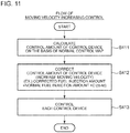
- FIG. 11 is a diagram showing a control flow for making the operational point arrive at a target position in an early stage.
- the corrected flow rate Qa and the turbo rotation speed Nt are calculated (S31).
- the above described current position calculation part 10C calculates the current position of the operational point 61 on the compressor map M1 (S32).
- the moving direction calculation part 10D and the moving velocity calculation part (10H) described above calculate the moving direction and the moving velocity of the operational point 61 on the compressor map M1 (S33).
- the moving direction determination part 10E determines whether the moving direction of the operational point 61 is in the target direction (S34, S35).
- S34 the distance La between the line 63L along the moving direction of the operational point 61 and the target position is calculated (see FIG. 6 ).
- S401 to S403 are the same as S181 to S183 in the above described embodiment, and thus not described here in detail.
- the arrival time estimation part 10I estimates the arrival time tb the operational point 61 takes to arrive at target position (S36), and the estimated arrival time tb and the second predetermined time td are compared (S37). If tb ⁇ td is satisfied (YES in S25), the process advances to S26. If tb ⁇ td is satisfied (NO in S37), the process advances to S41, and the moving velocity increasing control flow shown in FIG. 11 is performed, so as to make the operational point 61 arrive at the target position earlier.
- the control amount of the control devices 6, 26, 28 and the like is calculated on the basis of the normal control map.
- the control amount of the control devices 6, 26, 28 and the like calculated in S411 is corrected. For instance, if the control device is the waste-gate valve 28 and the valve opening degree of the waste-gate valve 28 is the control amount, a value C ⁇ (tb-td), which is a product of coefficient C and difference (tb-td) between the estimated arrival time tb and the second predetermined time td, is added to the valve opening degree (normal valve opening degree) of the waste-gate valve 28 calculated by the normal control map.
- the correction amount is changed in response to the difference (tb-td) between the estimated arrival time tb and the second predetermined time tc, and thereby it is possible to increase the correction amount in a case where the arrival time the operational point 61 takes to arrive at the target position is long, and to move the operational point 61 to the target position in an early stage.
- the control part 10A controls the waste-gate valve 28 so that the valve opening degree of the waste-gate valve 28 becomes the valve opening degree of the waste-gate valve 28 after correction (corrected valve opening degree) (S413).
- the moving velocity increasing control flow is performed repeatedly until it is determined that the arrival time tb the operational point 61 takes to arrive at the target position is below the second predetermined time tc.
- the control amount of the control devices 6, 26, 28 is calculated on the basis of the normal control map in S38, and the control devices 6, 26, 28 are controlled by the control part 10A in S39 on the basis of the control amount calculated in S38. That is, a normal operation control is performed.
- the compressor 22 is controlled on the basis of the moving velocity of the operational point 61 on the compressor map M1, in addition to the current position of the operational point 61 and the moving direction of the operational point 61 on the compressor map M1, and thereby it is possible to make the operational point 61 arrive at the target position earlier than in a normal control in a case where the operational point 61 takes too long to arrive at the target position under a normal control, as described above.
Landscapes
- Engineering & Computer Science (AREA)
- Chemical & Material Sciences (AREA)
- Combustion & Propulsion (AREA)
- Mechanical Engineering (AREA)
- General Engineering & Computer Science (AREA)
- Supercharger (AREA)
- Output Control And Ontrol Of Special Type Engine (AREA)
- Control Of Positive-Displacement Air Blowers (AREA)
Applications Claiming Priority (1)
| Application Number | Priority Date | Filing Date | Title |
|---|---|---|---|
| PCT/JP2015/082640 WO2017085854A1 (ja) | 2015-11-20 | 2015-11-20 | 過給システムの制御装置 |
Publications (3)
| Publication Number | Publication Date |
|---|---|
| EP3315749A1 true EP3315749A1 (de) | 2018-05-02 |
| EP3315749A4 EP3315749A4 (de) | 2018-09-12 |
| EP3315749B1 EP3315749B1 (de) | 2020-01-01 |
Family
ID=58719165
Family Applications (1)
| Application Number | Title | Priority Date | Filing Date |
|---|---|---|---|
| EP15908794.9A Active EP3315749B1 (de) | 2015-11-20 | 2015-11-20 | Steuerungsvorrichtung für ein aufladesystem |
Country Status (5)
| Country | Link |
|---|---|
| US (1) | US10697382B2 (de) |
| EP (1) | EP3315749B1 (de) |
| JP (1) | JP6389572B2 (de) |
| CN (1) | CN107532526B (de) |
| WO (1) | WO2017085854A1 (de) |
Cited By (2)
| Publication number | Priority date | Publication date | Assignee | Title |
|---|---|---|---|---|
| EP3401524A4 (de) * | 2016-03-08 | 2018-12-26 | Mitsubishi Heavy Industries Engine & Turbocharger, Ltd. | Steuerungsverfahren zur überspannungsvermeidung und steuerungsvorrichtung zur überspannungsvermeidung für abgasturbinenturbolader |
| SE1951201A1 (en) * | 2019-10-23 | 2021-02-23 | Scania Cv Ab | Four-Stroke Internal Combustion Engine and Method of Controlling Timings of an Exhaust Camshaft and an Intake Camshaft |
Families Citing this family (3)
| Publication number | Priority date | Publication date | Assignee | Title |
|---|---|---|---|---|
| CN110056435B (zh) * | 2018-01-18 | 2021-07-13 | 上汽通用汽车有限公司 | 基于无进气泄压阀的增压器降低整车油耗的控制方法和车辆 |
| US20200063651A1 (en) * | 2018-08-27 | 2020-02-27 | Garrett Transportation I Inc. | Method and system for controlling a variable-geometry compressor |
| CN113027596B (zh) * | 2021-04-26 | 2021-11-30 | 品源动力科技(广州)有限公司 | 一种涡轮增压系统、控制方法、存储介质及汽车 |
Family Cites Families (26)
| Publication number | Priority date | Publication date | Assignee | Title |
|---|---|---|---|---|
| US6401457B1 (en) * | 2001-01-31 | 2002-06-11 | Cummins, Inc. | System for estimating turbocharger compressor outlet temperature |
| JP3873742B2 (ja) | 2001-12-28 | 2007-01-24 | いすゞ自動車株式会社 | 可変容量ターボチャージャの制御装置 |
| US6647723B1 (en) * | 2002-08-20 | 2003-11-18 | International Engine Intellectual Property Company, Llc | Control strategy for counteracting incipient turbocharger surging using a variable valve actuation mechanism for through-cylinder bleed |
| JP2005240683A (ja) * | 2004-02-26 | 2005-09-08 | Nissan Motor Co Ltd | 内燃機関の排気浄化装置 |
| JP4381419B2 (ja) * | 2004-07-30 | 2009-12-09 | 株式会社小松製作所 | 内燃機関の給気制御装置 |
| US7076954B1 (en) * | 2005-03-31 | 2006-07-18 | Caterpillar Inc. | Turbocharger system |
| JP2007255265A (ja) | 2006-03-22 | 2007-10-04 | Toyota Motor Corp | エンジン過給システム |
| JP2007291961A (ja) | 2006-04-25 | 2007-11-08 | Toyota Motor Corp | 遠心式圧縮機を備える内燃機関の制御装置 |
| JP4857957B2 (ja) | 2006-06-30 | 2012-01-18 | 日産自動車株式会社 | エンジンの制御装置 |
| JP4375369B2 (ja) | 2006-08-10 | 2009-12-02 | トヨタ自動車株式会社 | 過給機付き内燃機関の制御装置 |
| EP2050943B1 (de) | 2006-08-10 | 2011-11-23 | Toyota Jidosha Kabushiki Kaisha | Steuervorrichtung für verbrennungsmotor mit turbolader |
| US20080034753A1 (en) * | 2006-08-15 | 2008-02-14 | Anthony Holmes Furman | Turbocharger Systems and Methods for Operating the Same |
| JP4512617B2 (ja) | 2007-06-26 | 2010-07-28 | 日立オートモティブシステムズ株式会社 | 内燃機関の制御装置および方法 |
| JP4577582B2 (ja) | 2007-08-31 | 2010-11-10 | 株式会社デンソー | ハイブリッド車の動力制御装置 |
| JP2009167963A (ja) | 2008-01-18 | 2009-07-30 | Toyota Motor Corp | 内燃機関の異常判定装置 |
| US7757549B2 (en) | 2008-02-21 | 2010-07-20 | Cummins Ip, Inc | Apparatus, system, and method for predictive control of a turbocharger |
| JP5195142B2 (ja) * | 2008-08-06 | 2013-05-08 | トヨタ自動車株式会社 | エアバイパスバルブの制御装置 |
| JP2010179861A (ja) * | 2009-02-09 | 2010-08-19 | Nissan Motor Co Ltd | ハイブリッド車両の制御装置 |
| US8397499B2 (en) * | 2009-08-24 | 2013-03-19 | Ford Global Technologies, Llc | Methods and systems for turbocharger control |
| JP2011126321A (ja) * | 2009-12-15 | 2011-06-30 | Mitsubishi Fuso Truck & Bus Corp | ハイブリッド電気自動車の制御装置 |
| US20110307127A1 (en) * | 2010-06-15 | 2011-12-15 | Kendall Roger Swenson | Method and system for controlling engine performance |
| WO2012032597A1 (ja) | 2010-09-06 | 2012-03-15 | トヨタ自動車株式会社 | 内燃機関の制御装置 |
| JP5828808B2 (ja) | 2012-06-29 | 2015-12-09 | 日立建機株式会社 | 油圧作業機械 |
| US9273597B2 (en) * | 2013-05-16 | 2016-03-01 | Ford Global Technologies, Llc | Method and system for operating an engine turbocharger waste gate |
| JP6377340B2 (ja) | 2013-12-04 | 2018-08-22 | 三菱重工業株式会社 | 過給システムの制御装置 |
| JP6287440B2 (ja) * | 2014-03-26 | 2018-03-07 | いすゞ自動車株式会社 | ハイブリッド車両とハイブリッド車両の制御方法 |
-
2015
- 2015-11-20 WO PCT/JP2015/082640 patent/WO2017085854A1/ja not_active Ceased
- 2015-11-20 CN CN201580078777.2A patent/CN107532526B/zh not_active Expired - Fee Related
- 2015-11-20 EP EP15908794.9A patent/EP3315749B1/de active Active
- 2015-11-20 US US15/578,470 patent/US10697382B2/en not_active Expired - Fee Related
- 2015-11-20 JP JP2017551483A patent/JP6389572B2/ja not_active Expired - Fee Related
Cited By (7)
| Publication number | Priority date | Publication date | Assignee | Title |
|---|---|---|---|---|
| EP3401524A4 (de) * | 2016-03-08 | 2018-12-26 | Mitsubishi Heavy Industries Engine & Turbocharger, Ltd. | Steuerungsverfahren zur überspannungsvermeidung und steuerungsvorrichtung zur überspannungsvermeidung für abgasturbinenturbolader |
| US10677149B2 (en) | 2016-03-08 | 2020-06-09 | Mitsubishi Heavy Industries Engine & Turbocharger, Ltd. | Surge avoidance control method and surge avoidance control device for exhaust turbine turbocharger |
| SE1951201A1 (en) * | 2019-10-23 | 2021-02-23 | Scania Cv Ab | Four-Stroke Internal Combustion Engine and Method of Controlling Timings of an Exhaust Camshaft and an Intake Camshaft |
| SE543456C2 (en) * | 2019-10-23 | 2021-02-23 | Scania Cv Ab | Four-Stroke Internal Combustion Engine and Method of Controlling Timings of an Exhaust Camshaft and an Intake Camshaft |
| WO2021080499A1 (en) * | 2019-10-23 | 2021-04-29 | Scania Cv Ab | Four-stroke internal combustion engine and method of controlling timings of an exhaust camshaft and an intake camshaft |
| US11686259B2 (en) | 2019-10-23 | 2023-06-27 | Scania Cv Ab | Four-stroke internal combustion engine and method of controlling timings of an exhaust camshaft and an intake camshaft |
| CN114466968B (zh) * | 2019-10-23 | 2024-04-23 | 斯堪尼亚商用车有限公司 | 四冲程内燃发动机和控制排气凸轮轴和进气凸轮轴的正时的方法 |
Also Published As
| Publication number | Publication date |
|---|---|
| WO2017085854A1 (ja) | 2017-05-26 |
| JPWO2017085854A1 (ja) | 2017-12-21 |
| US20180156141A1 (en) | 2018-06-07 |
| EP3315749A4 (de) | 2018-09-12 |
| EP3315749B1 (de) | 2020-01-01 |
| JP6389572B2 (ja) | 2018-09-12 |
| CN107532526B (zh) | 2020-11-10 |
| US10697382B2 (en) | 2020-06-30 |
| CN107532526A (zh) | 2018-01-02 |
Similar Documents
| Publication | Publication Date | Title |
|---|---|---|
| EP3315749B1 (de) | Steuerungsvorrichtung für ein aufladesystem | |
| KR102214409B1 (ko) | 엔진 시스템의 제어 장치 및 제어 방법 | |
| EP3056715A1 (de) | Systeme und verfahren zur steuerung der einlasslufttemperatur eines zwischengekühlten gasturbinenmotors | |
| US11530650B2 (en) | Gas turbine engine with active variable turbine cooling | |
| CN106605055B (zh) | 用于致动带有排气再循环的增压式内燃发动机的排气再循环阀的方法和设备 | |
| US20160153365A1 (en) | Method of Operation of a Gas Turbine Engine | |
| CN107063362A (zh) | 用于改进参数测量的方法和系统 | |
| EP3051098A1 (de) | Twin-scroll-turboladervorrichtung mit verbesserter turboreaktion | |
| RU2337250C2 (ru) | Способ управления газотурбинным двигателем на динамических режимах разгона и дросселирования | |
| JP4835474B2 (ja) | ターボ過給機制御システム | |
| US10344767B2 (en) | Method for compressor surge detection to enable model base air estimation | |
| EP3447268B1 (de) | Triebwerkssteuerungssystem | |
| CN110318864B (zh) | 基于海拔的两级增压系统开度修正方法及两级增压系统 | |
| CN105143611B (zh) | 燃气轮机和用于操作燃气轮机的方法 | |
| RU2435972C1 (ru) | Способ управления расходом топлива в многоколлекторную камеру сгорания газотурбинного двигателя | |
| US9896992B2 (en) | Pressure-charged combustion engine having a double-flow turbine and grouped cylinders | |
| JP5664774B2 (ja) | 内燃機関の制御装置 | |
| CN103967594B (zh) | 大型双冲程柴油发动机以及获得其中的蝶形阀特征的方法 | |
| RU2431753C1 (ru) | Способ управления газотурбинной установкой | |
| RU2431051C1 (ru) | Способ управления газотурбинной установкой | |
| EP3376012B1 (de) | Antriebssystem für gasmotor | |
| CN105874172B (zh) | 确定方法和燃气涡轮机 | |
| JP2009156086A (ja) | ガスタービンエンジンの制御装置 | |
| RU2422657C1 (ru) | Способ управления газотурбинной электростанцией | |
| KR101861858B1 (ko) | 내연기관 작동 방법 및 그 장치 |
Legal Events
| Date | Code | Title | Description |
|---|---|---|---|
| STAA | Information on the status of an ep patent application or granted ep patent |
Free format text: STATUS: THE INTERNATIONAL PUBLICATION HAS BEEN MADE |
|
| PUAI | Public reference made under article 153(3) epc to a published international application that has entered the european phase |
Free format text: ORIGINAL CODE: 0009012 |
|
| STAA | Information on the status of an ep patent application or granted ep patent |
Free format text: STATUS: REQUEST FOR EXAMINATION WAS MADE |
|
| 17P | Request for examination filed |
Effective date: 20180124 |
|
| AK | Designated contracting states |
Kind code of ref document: A1 Designated state(s): AL AT BE BG CH CY CZ DE DK EE ES FI FR GB GR HR HU IE IS IT LI LT LU LV MC MK MT NL NO PL PT RO RS SE SI SK SM TR |
|
| AX | Request for extension of the european patent |
Extension state: BA ME |
|
| REG | Reference to a national code |
Ref country code: DE Ref legal event code: R079 Ref document number: 602015044992 Country of ref document: DE Free format text: PREVIOUS MAIN CLASS: F02D0023020000 Ipc: F02D0041000000 |
|
| A4 | Supplementary search report drawn up and despatched |
Effective date: 20180809 |
|
| RIC1 | Information provided on ipc code assigned before grant |
Ipc: F02B 37/18 20060101ALI20180804BHEP Ipc: F02D 23/02 20060101ALI20180804BHEP Ipc: F02D 41/00 20060101AFI20180804BHEP Ipc: F02D 41/14 20060101ALI20180804BHEP Ipc: F02B 37/22 20060101ALI20180804BHEP |
|
| RAP1 | Party data changed (applicant data changed or rights of an application transferred) |
Owner name: MITSUBISHI HEAVY INDUSTRIES ENGINE & TURBOCHARGER, |
|
| DAV | Request for validation of the european patent (deleted) | ||
| DAX | Request for extension of the european patent (deleted) | ||
| GRAP | Despatch of communication of intention to grant a patent |
Free format text: ORIGINAL CODE: EPIDOSNIGR1 |
|
| STAA | Information on the status of an ep patent application or granted ep patent |
Free format text: STATUS: GRANT OF PATENT IS INTENDED |
|
| INTG | Intention to grant announced |
Effective date: 20190709 |
|
| GRAS | Grant fee paid |
Free format text: ORIGINAL CODE: EPIDOSNIGR3 |
|
| GRAA | (expected) grant |
Free format text: ORIGINAL CODE: 0009210 |
|
| STAA | Information on the status of an ep patent application or granted ep patent |
Free format text: STATUS: THE PATENT HAS BEEN GRANTED |
|
| AK | Designated contracting states |
Kind code of ref document: B1 Designated state(s): AL AT BE BG CH CY CZ DE DK EE ES FI FR GB GR HR HU IE IS IT LI LT LU LV MC MK MT NL NO PL PT RO RS SE SI SK SM TR |
|
| REG | Reference to a national code |
Ref country code: GB Ref legal event code: FG4D |
|
| REG | Reference to a national code |
Ref country code: CH Ref legal event code: EP Ref country code: AT Ref legal event code: REF Ref document number: 1220061 Country of ref document: AT Kind code of ref document: T Effective date: 20200115 |
|
| REG | Reference to a national code |
Ref country code: DE Ref legal event code: R096 Ref document number: 602015044992 Country of ref document: DE |
|
| REG | Reference to a national code |
Ref country code: IE Ref legal event code: FG4D |
|
| REG | Reference to a national code |
Ref country code: NL Ref legal event code: MP Effective date: 20200101 |
|
| REG | Reference to a national code |
Ref country code: LT Ref legal event code: MG4D |
|
| PG25 | Lapsed in a contracting state [announced via postgrant information from national office to epo] |
Ref country code: NL Free format text: LAPSE BECAUSE OF FAILURE TO SUBMIT A TRANSLATION OF THE DESCRIPTION OR TO PAY THE FEE WITHIN THE PRESCRIBED TIME-LIMIT Effective date: 20200101 Ref country code: FI Free format text: LAPSE BECAUSE OF FAILURE TO SUBMIT A TRANSLATION OF THE DESCRIPTION OR TO PAY THE FEE WITHIN THE PRESCRIBED TIME-LIMIT Effective date: 20200101 Ref country code: RS Free format text: LAPSE BECAUSE OF FAILURE TO SUBMIT A TRANSLATION OF THE DESCRIPTION OR TO PAY THE FEE WITHIN THE PRESCRIBED TIME-LIMIT Effective date: 20200101 Ref country code: CZ Free format text: LAPSE BECAUSE OF FAILURE TO SUBMIT A TRANSLATION OF THE DESCRIPTION OR TO PAY THE FEE WITHIN THE PRESCRIBED TIME-LIMIT Effective date: 20200101 Ref country code: PT Free format text: LAPSE BECAUSE OF FAILURE TO SUBMIT A TRANSLATION OF THE DESCRIPTION OR TO PAY THE FEE WITHIN THE PRESCRIBED TIME-LIMIT Effective date: 20200527 Ref country code: NO Free format text: LAPSE BECAUSE OF FAILURE TO SUBMIT A TRANSLATION OF THE DESCRIPTION OR TO PAY THE FEE WITHIN THE PRESCRIBED TIME-LIMIT Effective date: 20200401 Ref country code: LT Free format text: LAPSE BECAUSE OF FAILURE TO SUBMIT A TRANSLATION OF THE DESCRIPTION OR TO PAY THE FEE WITHIN THE PRESCRIBED TIME-LIMIT Effective date: 20200101 |
|
| PG25 | Lapsed in a contracting state [announced via postgrant information from national office to epo] |
Ref country code: LV Free format text: LAPSE BECAUSE OF FAILURE TO SUBMIT A TRANSLATION OF THE DESCRIPTION OR TO PAY THE FEE WITHIN THE PRESCRIBED TIME-LIMIT Effective date: 20200101 Ref country code: SE Free format text: LAPSE BECAUSE OF FAILURE TO SUBMIT A TRANSLATION OF THE DESCRIPTION OR TO PAY THE FEE WITHIN THE PRESCRIBED TIME-LIMIT Effective date: 20200101 Ref country code: BG Free format text: LAPSE BECAUSE OF FAILURE TO SUBMIT A TRANSLATION OF THE DESCRIPTION OR TO PAY THE FEE WITHIN THE PRESCRIBED TIME-LIMIT Effective date: 20200401 Ref country code: GR Free format text: LAPSE BECAUSE OF FAILURE TO SUBMIT A TRANSLATION OF THE DESCRIPTION OR TO PAY THE FEE WITHIN THE PRESCRIBED TIME-LIMIT Effective date: 20200402 Ref country code: IS Free format text: LAPSE BECAUSE OF FAILURE TO SUBMIT A TRANSLATION OF THE DESCRIPTION OR TO PAY THE FEE WITHIN THE PRESCRIBED TIME-LIMIT Effective date: 20200501 Ref country code: HR Free format text: LAPSE BECAUSE OF FAILURE TO SUBMIT A TRANSLATION OF THE DESCRIPTION OR TO PAY THE FEE WITHIN THE PRESCRIBED TIME-LIMIT Effective date: 20200101 |
|
| REG | Reference to a national code |
Ref country code: DE Ref legal event code: R097 Ref document number: 602015044992 Country of ref document: DE |
|
| PG25 | Lapsed in a contracting state [announced via postgrant information from national office to epo] |
Ref country code: SK Free format text: LAPSE BECAUSE OF FAILURE TO SUBMIT A TRANSLATION OF THE DESCRIPTION OR TO PAY THE FEE WITHIN THE PRESCRIBED TIME-LIMIT Effective date: 20200101 Ref country code: SM Free format text: LAPSE BECAUSE OF FAILURE TO SUBMIT A TRANSLATION OF THE DESCRIPTION OR TO PAY THE FEE WITHIN THE PRESCRIBED TIME-LIMIT Effective date: 20200101 Ref country code: ES Free format text: LAPSE BECAUSE OF FAILURE TO SUBMIT A TRANSLATION OF THE DESCRIPTION OR TO PAY THE FEE WITHIN THE PRESCRIBED TIME-LIMIT Effective date: 20200101 Ref country code: DK Free format text: LAPSE BECAUSE OF FAILURE TO SUBMIT A TRANSLATION OF THE DESCRIPTION OR TO PAY THE FEE WITHIN THE PRESCRIBED TIME-LIMIT Effective date: 20200101 Ref country code: EE Free format text: LAPSE BECAUSE OF FAILURE TO SUBMIT A TRANSLATION OF THE DESCRIPTION OR TO PAY THE FEE WITHIN THE PRESCRIBED TIME-LIMIT Effective date: 20200101 Ref country code: RO Free format text: LAPSE BECAUSE OF FAILURE TO SUBMIT A TRANSLATION OF THE DESCRIPTION OR TO PAY THE FEE WITHIN THE PRESCRIBED TIME-LIMIT Effective date: 20200101 |
|
| PLBE | No opposition filed within time limit |
Free format text: ORIGINAL CODE: 0009261 |
|
| STAA | Information on the status of an ep patent application or granted ep patent |
Free format text: STATUS: NO OPPOSITION FILED WITHIN TIME LIMIT |
|
| REG | Reference to a national code |
Ref country code: AT Ref legal event code: MK05 Ref document number: 1220061 Country of ref document: AT Kind code of ref document: T Effective date: 20200101 |
|
| 26N | No opposition filed |
Effective date: 20201002 |
|
| PG25 | Lapsed in a contracting state [announced via postgrant information from national office to epo] |
Ref country code: AT Free format text: LAPSE BECAUSE OF FAILURE TO SUBMIT A TRANSLATION OF THE DESCRIPTION OR TO PAY THE FEE WITHIN THE PRESCRIBED TIME-LIMIT Effective date: 20200101 Ref country code: IT Free format text: LAPSE BECAUSE OF FAILURE TO SUBMIT A TRANSLATION OF THE DESCRIPTION OR TO PAY THE FEE WITHIN THE PRESCRIBED TIME-LIMIT Effective date: 20200101 |
|
| PGFP | Annual fee paid to national office [announced via postgrant information from national office to epo] |
Ref country code: GB Payment date: 20201112 Year of fee payment: 6 Ref country code: FR Payment date: 20201013 Year of fee payment: 6 |
|
| PG25 | Lapsed in a contracting state [announced via postgrant information from national office to epo] |
Ref country code: SI Free format text: LAPSE BECAUSE OF FAILURE TO SUBMIT A TRANSLATION OF THE DESCRIPTION OR TO PAY THE FEE WITHIN THE PRESCRIBED TIME-LIMIT Effective date: 20200101 Ref country code: PL Free format text: LAPSE BECAUSE OF FAILURE TO SUBMIT A TRANSLATION OF THE DESCRIPTION OR TO PAY THE FEE WITHIN THE PRESCRIBED TIME-LIMIT Effective date: 20200101 |
|
| PG25 | Lapsed in a contracting state [announced via postgrant information from national office to epo] |
Ref country code: MC Free format text: LAPSE BECAUSE OF FAILURE TO SUBMIT A TRANSLATION OF THE DESCRIPTION OR TO PAY THE FEE WITHIN THE PRESCRIBED TIME-LIMIT Effective date: 20200101 |
|
| REG | Reference to a national code |
Ref country code: CH Ref legal event code: PL |
|
| PG25 | Lapsed in a contracting state [announced via postgrant information from national office to epo] |
Ref country code: LU Free format text: LAPSE BECAUSE OF NON-PAYMENT OF DUE FEES Effective date: 20201120 |
|
| REG | Reference to a national code |
Ref country code: BE Ref legal event code: MM Effective date: 20201130 |
|
| PG25 | Lapsed in a contracting state [announced via postgrant information from national office to epo] |
Ref country code: CH Free format text: LAPSE BECAUSE OF NON-PAYMENT OF DUE FEES Effective date: 20201130 Ref country code: LI Free format text: LAPSE BECAUSE OF NON-PAYMENT OF DUE FEES Effective date: 20201130 |
|
| PG25 | Lapsed in a contracting state [announced via postgrant information from national office to epo] |
Ref country code: IE Free format text: LAPSE BECAUSE OF NON-PAYMENT OF DUE FEES Effective date: 20201120 |
|
| PGFP | Annual fee paid to national office [announced via postgrant information from national office to epo] |
Ref country code: DE Payment date: 20210929 Year of fee payment: 7 |
|
| PG25 | Lapsed in a contracting state [announced via postgrant information from national office to epo] |
Ref country code: TR Free format text: LAPSE BECAUSE OF FAILURE TO SUBMIT A TRANSLATION OF THE DESCRIPTION OR TO PAY THE FEE WITHIN THE PRESCRIBED TIME-LIMIT Effective date: 20200101 Ref country code: MT Free format text: LAPSE BECAUSE OF FAILURE TO SUBMIT A TRANSLATION OF THE DESCRIPTION OR TO PAY THE FEE WITHIN THE PRESCRIBED TIME-LIMIT Effective date: 20200101 Ref country code: CY Free format text: LAPSE BECAUSE OF FAILURE TO SUBMIT A TRANSLATION OF THE DESCRIPTION OR TO PAY THE FEE WITHIN THE PRESCRIBED TIME-LIMIT Effective date: 20200101 |
|
| PG25 | Lapsed in a contracting state [announced via postgrant information from national office to epo] |
Ref country code: MK Free format text: LAPSE BECAUSE OF FAILURE TO SUBMIT A TRANSLATION OF THE DESCRIPTION OR TO PAY THE FEE WITHIN THE PRESCRIBED TIME-LIMIT Effective date: 20200101 Ref country code: AL Free format text: LAPSE BECAUSE OF FAILURE TO SUBMIT A TRANSLATION OF THE DESCRIPTION OR TO PAY THE FEE WITHIN THE PRESCRIBED TIME-LIMIT Effective date: 20200101 |
|
| GBPC | Gb: european patent ceased through non-payment of renewal fee |
Effective date: 20211120 |
|
| PG25 | Lapsed in a contracting state [announced via postgrant information from national office to epo] |
Ref country code: BE Free format text: LAPSE BECAUSE OF NON-PAYMENT OF DUE FEES Effective date: 20201130 |
|
| PG25 | Lapsed in a contracting state [announced via postgrant information from national office to epo] |
Ref country code: GB Free format text: LAPSE BECAUSE OF NON-PAYMENT OF DUE FEES Effective date: 20211120 |
|
| PG25 | Lapsed in a contracting state [announced via postgrant information from national office to epo] |
Ref country code: FR Free format text: LAPSE BECAUSE OF NON-PAYMENT OF DUE FEES Effective date: 20211130 |
|
| REG | Reference to a national code |
Ref country code: DE Ref legal event code: R119 Ref document number: 602015044992 Country of ref document: DE |
|
| PG25 | Lapsed in a contracting state [announced via postgrant information from national office to epo] |
Ref country code: DE Free format text: LAPSE BECAUSE OF NON-PAYMENT OF DUE FEES Effective date: 20230601 |