EP3315775B1 - Algorithmes de diagnostic de pompe en temps réel et leur application - Google Patents
Algorithmes de diagnostic de pompe en temps réel et leur application Download PDFInfo
- Publication number
- EP3315775B1 EP3315775B1 EP17202438.2A EP17202438A EP3315775B1 EP 3315775 B1 EP3315775 B1 EP 3315775B1 EP 17202438 A EP17202438 A EP 17202438A EP 3315775 B1 EP3315775 B1 EP 3315775B1
- Authority
- EP
- European Patent Office
- Prior art keywords
- pump
- time
- data points
- real
- card
- Prior art date
- Legal status (The legal status is an assumption and is not a legal conclusion. Google has not performed a legal analysis and makes no representation as to the accuracy of the status listed.)
- Active
Links
Images


Classifications
-
- E—FIXED CONSTRUCTIONS
- E21—EARTH OR ROCK DRILLING; MINING
- E21B—EARTH OR ROCK DRILLING; OBTAINING OIL, GAS, WATER, SOLUBLE OR MELTABLE MATERIALS OR A SLURRY OF MINERALS FROM WELLS
- E21B47/00—Survey of boreholes or wells
- E21B47/008—Monitoring of down-hole pump systems, e.g. for the detection of "pumped-off" conditions
- E21B47/009—Monitoring of walking-beam pump systems
-
- E—FIXED CONSTRUCTIONS
- E21—EARTH OR ROCK DRILLING; MINING
- E21B—EARTH OR ROCK DRILLING; OBTAINING OIL, GAS, WATER, SOLUBLE OR MELTABLE MATERIALS OR A SLURRY OF MINERALS FROM WELLS
- E21B47/00—Survey of boreholes or wells
- E21B47/09—Locating or determining the position of objects in boreholes or wells, e.g. the position of an extending arm; Identifying the free or blocked portions of pipes
-
- F—MECHANICAL ENGINEERING; LIGHTING; HEATING; WEAPONS; BLASTING
- F04—POSITIVE - DISPLACEMENT MACHINES FOR LIQUIDS; PUMPS FOR LIQUIDS OR ELASTIC FLUIDS
- F04B—POSITIVE-DISPLACEMENT MACHINES FOR LIQUIDS; PUMPS
- F04B47/00—Pumps or pumping installations specially adapted for raising fluids from great depths, e.g. well pumps
- F04B47/02—Pumps or pumping installations specially adapted for raising fluids from great depths, e.g. well pumps the driving mechanisms being situated at ground level
-
- F—MECHANICAL ENGINEERING; LIGHTING; HEATING; WEAPONS; BLASTING
- F04—POSITIVE - DISPLACEMENT MACHINES FOR LIQUIDS; PUMPS FOR LIQUIDS OR ELASTIC FLUIDS
- F04B—POSITIVE-DISPLACEMENT MACHINES FOR LIQUIDS; PUMPS
- F04B49/00—Control, e.g. of pump delivery, or pump pressure of, or safety measures for, machines, pumps, or pumping installations, not otherwise provided for, or of interest apart from, groups F04B1/00 - F04B47/00
- F04B49/06—Control using electricity
- F04B49/065—Control using electricity and making use of computers
Definitions
- the inventions disclosed and taught herein relate generally to pump diagnostic methods, and more specifically real-time and near real-time pump diagnostic techniques and approaches for use with rod pump and similar well pumping systems.
- Lukasiewicz obtained the solution to the wave equation of the rod strings of some deviated wells through the finite element method by considering the axial and transversal motions [ Lukasiewicz, S.A., Journal of Canadian Petroleum Technology, Vol. 29 (6), pp. 76-79 (1990 ); Lukasiewicz, S.A., Proc. Of Production Operations Symposium, April 1991, Oklahoma City, Oklahoma; pp. 313-321 ].
- Gibbs proposed a diagnostic solution to the deviated wells by including the Coulomb friction in the wave equation [ Gibbs, S.G., Journal of Petroleum Technology, Vol. 44 (7), pp. 774-781 (1992 )].
- the data points of the polished rod position and load of a stroke cycle are acquired and displayed first.
- the diagnostic algorithm is executed to obtain the pump position and load.
- the time delay between the display of the first data point of the pump card and the display of the first data point of the surface card is between one stroke cycle and two stroke cycles.
- the delay time is the accumulation of the polished rod stroke cycle, the time spent on filtering and interpolation of the polished rod data, and the time spent on executing the diagnostic algorithm.
- the instant disclosure addresses the issue of displaying a pump card in real-time or near real-time mode using several real-time or near real-time diagnostic techniques and methods, including the finite difference and Fourier series solutions to the wave equation of the rod string in a well.
- the real-time pump diagnostic technique has three main benefits: 1) it provides the real-time or near real-time pump information; 2) it advances the pump-off control action by about half the pumping cycle; 3) it may be useful for the active speed control of the oil pump.
- the technique for calculating the pump card in real-time is developed, and the simulation results are reported.
- the Fourier series method by using the periodicity of the signal, the pump data point (pump position and pump load) at any time point is obtained, and the surface and pump data points can be displayed and erased synchronously.
- the wave propagation delay law is applied so that the pump motion is delayed at a proper time relative to the polished rod motion.
- the inventions disclosed and taught herein are directed to techniques for displaying a pump card in real-time or near real-time synchronization with a surface card, and the implementation of such methods and techniques.
- real-time and near real-time methods including both methods of finite difference and Fourier series analysis, for analyzing and displaying pump cards and surface cards are described.
- a polished rod load can be derived from a direct measurement through a load cell or from a calculation through a motor torque.
- a first surface stroke may refer to any stable surface stroke after pumping is started, and it does not necessarily refer to the first surface stroke which occurs immediately after the pumping unit is started.
- Any surface data point is displayed once it is measured, and any pump card data point is displayed once it is calculated.
- a surface card is erased only after its cycle is complete, a pump card is erased only after its cycle is complete, the surface card and its corresponding pump card can be erased at the same time or in a sequence with a delay.
- Methods for calculating the pump data points in real-time are provided, the methods calculate and display the current pump data point in the time interval between the last surface data point and the current surface data point, and the methods calculate the data points of the first pump card before or when the first surface stroke is completed .
- Data points may include but are not limited to data points that may be measured, derived or inferred, such as position, load, pressure, motor torque, or motor current.
- a real-time pump card point can be obtained every few surface data points to give more time for executing the real-time pump diagnostic algorithms, and the real-time pump diagnostic algorithms are suitable for strokes with a varying number of data points.
- the real-time pump diagnostic methods are applicable to vertical wells, horizontal wells and deviated wells with single or multi-taper rod strings.
- the real-time pump diagnostic methods have advantages for prompt diagnostic of the pump conditions, and prompt control of the pump.
- substantially real time refers to a short period of time between process steps. Preferably, something that occurs in “substantially real time” occurs within a time period of less than 10 seconds, more preferably less than 5, 4, 2, 1, 0.5, 0.2, 0.1, 0.01 seconds, or less.
- computing an algorithm or pump card metric is performed in substantially real time relative to when the activity measurement used to compute the metric was taken.
- near real-time refers to the time delay introduced, by automated data processing or network transmission, between the occurrence of an event and the use of the processed data, such as for display or feedback and control purposes.
- NRT near real-time display depicts an event or situation as it existed at the current time minus the processing time, as nearly the time of the live event.
- the executed instructions may create structures and functions for implementing the actions specified in the block diagrams and operational illustrations.
- the functions/actions/structures noted in the figures may occur out of the order noted in the block diagrams and operational illustrations. For example, two operations shown as occurring in succession, in fact, may be executed substantially concurrently or the operations may be executed in the reverse order, depending upon the functionality/acts/structure involved.
- Applicants have created real-time and near real-time pump diagnostic techniques and methods to generate a pump motion capable of lagging the polished rod motion, or being synchronous with the polished rod motion. Such methods may also detect the incomplete pump fillage and other pump conditions in a timely manner.
- the following are examples of real-time and near real-time pump diagnostic techniques and methods to generate a pump motion capable of lagging the polished rod motion, or being synchronous with the polished rod motion using the finite deference equations.
- a generalized model for the deviated well is developed.
- C(x, t) is the Coulomb friction force on the rod segment of unit length and varies over time at every node in lbs/ft
- t is the time in seconds
- u(x,t) is the rod displacement (deformation) in ft at the axial distance x and the time t
- A the rod cross-sectional area in in 2
- ⁇ is the dimensionless damping factor
- L is the total rod length in ft
- ⁇ is the density of the rod material in lbm/ft 3
- g c is the gravity conversion
- H 1 ⁇ A + 144 cg c ⁇ t ⁇ x 2 144 EAg c ⁇ t 2
- H 2 2 ⁇ ⁇ ⁇ ⁇ x 2 144 Eg c ⁇ t 2 + c ⁇ ⁇ ⁇ ⁇ x 2 144 Eg c ⁇ ⁇ t ⁇ 2
- H 3 ⁇ ⁇ ⁇ x 2 144 Eg c ⁇ t 2
- H 4 ⁇ x 2 AE .
- Equation (2) is solved for the current pump position and load in every sampling time interval.
- a beam pump unit may have many input sensors to the Well Manager controller.
- Well ManagerTM is a Lufkin product.
- the input sensors may be used in the display of a real-time pump card.
- the first input may be from a magnet that monitors the motor revolution. Polished rod position or load data point may correspond to a complete motor revolution which is sensed by this magnet.
- the second input may be from the other magnet that sends a signal to the controller at the end of a complete stroke cycle.
- the data acquired between the two input signals of the second magnet may represent the data that spans a stroke cycle of the polished rod.
- the surface and pump cards may be erased once the second magnet is triggered.
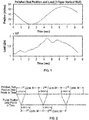
- FIG. 1 is an exemplary illustration of a polished rod position and load for a real vertical well with a three-taper rod string.
- This well is named as Well 1.
- the number of the data points of the polished rod position or load is 205.
- the well parameters are listed in Table 1.
- the polished rod position takes the substantially full, or complete, sinusoidal wave form.
- the pump fillage is complete.
- a surface or pump card Once a surface or pump card is complete, it may be immediately erased. To have a complete cycle of data for the pump card, more than one cycle of data for the polished rod may be needed. The additional data of the polished rod may come from the next cycle. It may use the 2N-3 beginning data points of the next surface cycle to calculate the 2N-3 ending data points of the current pump cycle.
- FIG. 2 illustrates the sequences of the polished rod position and the relevant pump position.
- a surface data point may be displayed as soon as it is available. Once M surface data points are displayed, the surface card may be erased and the surface card for the next stroke cycle may start to be displayed.
- the first 2N-3 data points of the polished rod position and load of the first stroke are available, the first data point of the pump card may be immediately calculated and displayed. Then, the moving triangular window as shown in FIG. 2 may be advanced in time by one data point step since the (2N-2) th surface data point is available. With this new array of 2N-3 surface data points, the second pump data point may be calculated and displayed. Data shifting, calculation and displaying may continue until M pump data points are displayed. Then, a pump cycle is completed, the pump card may be erased and the pump card for the next stroke cycle may start to be displayed.
- An exemplary Well 1 may be simulated.
- the 2N-3 points of the surface card of the exemplary Well 1 are being displayed and the first pump card data point is calculated and displayed.
- the closing of the surface card is ahead of closing of the pump card. Either card may be erased once it is completed.
- FIG. 4 the beginning of the pump card is being displayed. Displaying of the surface card is ahead of displaying of the pump card.
- FIG. 5 illustrates that at a time point which is the integer multiplication of M, the surface card of Well 1 is completed but the pump card is not completed.
- FIG. 6 illustrates that the pump card of Well 1 for its stroke cycle is complete when the 2N-3 surface card data points for its next stroke cycle are acquired and displayed.
- the grid table for a data point of the pump card is shown in Table 2.
- the horizontal grids are along the time axis.
- the vertical grids are along the rod string position axis.
- b represents the grids of the node 1 and 2 as the boundary conditions.
- X represents the useless grids which need no calculation.
- U represents the grids which have to be solved in order to get a data point of the pump node. In this case, the grid on the coordinates (6,7) will be solved.
- the conventional finite difference method has to solve 55 grid points. However, the new algorithm proposed in this report needs to solve only 25 grid points.
- the discussion and details presented herein proposes two techniques for calculating the pump card in synchronization with its surface card under the finite difference method.
- the first technique synchronously displays and erases the surface and pump cards.
- the second technique displays the data point of a surface or pump card as soon as it is available and erases a card once it is completed. Either technique can be refined.
- the proposed techniques provide the closed pump cards based on which pump condition can be diagnosed or pump can be shut off or made slow. Moreover, calculation of the useless data grid points in the finite difference iteration may be avoided. The computational efficiency may be doubled.
- the real-time pump card invention can also be applied to the Fourier series platform, as is discussed below.
- the following is an example of real-time and near real-time pump diagnostic techniques and methods to generate a pump motion capable of being synchronous with the polished rod motion using wave equations and Fourier series transforms.
- Equation (1) v in Equation (1).
- R n x t O n x cos nwt + P n x sin nwt
- O n x ⁇ n cosh ⁇ n x + ⁇ n sinh ⁇ n x sin ⁇ n x + ⁇ n sinh ⁇ n x + ⁇ n cosh ⁇ n x cos ⁇ n x
- P n x ⁇ n sinh ⁇ n x + ⁇ n cosh ⁇ n x cos ⁇ n x ⁇ ⁇ n cosh ⁇ n x + v n sinh ⁇ n x sin ⁇ n x
- T c is the pumping cycle
- w 2 ⁇ ⁇ T c is the angular frequency of the polished rod
- ⁇ n nw a 2 1 + 1 + c nw 2
- ⁇ n nw a 2 ⁇ 1 +
- EA ⁇ P n x ⁇ x ⁇ n cosh ⁇ n x + EA ⁇ n ⁇ n ⁇ ⁇ n ⁇ n sinh ⁇ n x cos ⁇ n x ⁇ ⁇ n sinh ⁇ n x + EA ⁇ n ⁇ n + ⁇ n ⁇ n cosh ⁇ n x sin ⁇ n x .
- Rod strings may have different rod sizes.
- the real-time diagnostic equations should handle these tapered-rod strings.
- the notation of the Fourier coefficients is extended to include two subscripts i ⁇ n , i ⁇ n , i ⁇ n , and i ⁇ n in which the left subscript denotes the i th taper in the tapered rod string and the right subscript denotes the order of the coefficient as previously.
- the polished rod data are associated with the first rod interval. Therefore, i ⁇ n , i ⁇ n , i ⁇ n , and i ⁇ n are Fourier coefficients obtained from harmonic analysis of the polished rod load and position.
- the surface and pump cards are displayed and erased synchronously.
- FIG. 7 is an exemplary illustration of the sequences of the polished rod position and the relevant pump position.
- L is defined as the pump depth.
- the corresponding data points of the pump load u ( L,t ) are calculated through Equation (10).
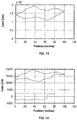
- FIGS. 8 , 9 and 10 show the surface and pump cards after the first stroke at the 68 th time point, the 136 th time point and the last time point of a stroke cycle for Well 1.
- the surface and pump cards are displayed simultaneously.
- the pump card obtained is the same as the one obtained via the conventional Fourier series algorithm.
- This disclosure proposes a technique for real-time pump diagnostic of the pump conditions of oil wells.
- the Fourier series algorithm acts as a platform where the new real-time Fourier series algorithm is developed.
- the current pump position and load corresponding to the current surface position and load are calculated from an amount of current and past surface data points that span a stroke cycle.
- This technique generates the same quality of the pump cards as the non real-time Fourier series algorithm generates.
- the proposed technique provides the closed pump cards based on which pump condition can be diagnosed, the pump can be shut off or the pump speed can be changed. By calculating only the pump position at the last time point of a dynamic stroke period, computational efficiency is substantially improved. This fast calculation is helpful to successful implementation of the real-time pump diagnostic technique since the execution time of the whole algorithm is desired to be shorter than any sampling time interval of the surface data.
- This disclosure proposes techniques, including those based on the finite difference method or the Fourier series method that may generate the pump motion in real-time or near real-time corresponding to the polished rod motion.
- the force wave starting at the polished rod driver may not reach the pump instantly. Therefore, the pump motion may lag the polished rod motion by the force wave propagation delay time. This delay time may be so long for a deep well that the pump is still moving in one direction while the polished rod is moving in the opposite direction. For shallow wells, this kind of motion delay phenomenon may be negligible.
- This disclosure proposes additional methods that map the wave propagation delay time to some parameters in the solutions of the wave equations so that the pump motion properly lags the polished motion in the pump diagnostic. The real-time mode of the pump motion may be approximately obtained.
- the force wave may propagate from the polished rod to the pump by going through a few tapers.
- Equation (2) The finite difference equation for a rod string may be represented by Equation (2) where
- a stroke cycle has the M data points.
- T is defined as the stroke cycle.
- N may be rounded to its nearest integer towards infinity.
- the number of nodes is approximately 2N.
- a value for N that is not less than a certain integer value may be required for shallow wells since small 2N may cause the solution to be unstable.
- This disclosure proposes techniques for the implementation of propagation delay time with the Fourier Series Method. For every current surface data point, by using a cycle of the current and past surface data points, a full cycle of pump data points may be obtained. For the end of the i th taper, instead of using the last data point of this pump cycle, a data point which has the delay time of t i may be used.
- the pump cycle period is defined as T.
- the pump card can be divided into the four phases:
- the pump fillage for this pump card is 20%.
- the time point t 4 on the surface card corresponds to the critical pump-off point.
- the surface card starts at the time point t 1 that corresponds to the bottom of the down stroke.
- the controller has to wait for the time interval ( t 1 - t 4 ) between the time point t 1 and the time point t 4 that is required to complete the stroke cycle and the additional time interval ( t 5 - t 1 ) that is required for executing the algorithm to obtain the pump card.
- a pump card may be obtained at the time point t 5 .
- ⁇ t is the delay time for switching off or slowing down the pump after the pump-off condition at t 4 is detected.
- a pump card can be obtained along with the surface card as shown FIG. 7 .
- the sinusoidal pump motion has a phase delay compared to the sinusoidal polished rod motion.
- the surface may reach the critical pump-off control point at the time point t 4 but the pump may reach the critical pump-off control point at the time point t p 4 .
- the real-time pump diagnostic method can turn off or slow down the pump earlier in an amount of time ⁇ t - ⁇ .
- SROD was used to synthesize the polished rod position and load as shown in FIG. 12 .
- the well parameters are listed in Table 1.
- the pump has 100% fillage in the first stroke, 80% fillage in the second stroke, 60% fillage in the third stroke, 40% fillage in the fourth stroke, 20% fillage in the fifth stroke, and 100% fillage in the last stroke.
- the Fourier series real-time diagnostic method is used. The propagation delay is considered.
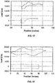
- the surface card with 100% fillage in the first stroke is shown in FIG. 13 and the pump card is not available.
- the surface and pump cards with 80% fillage are shown in FIG. 14 .
- the surface and pump cards with 60% fillage are shown in FIG. 15 .
- the surface and pump cards with 40% fillage are shown in FIG. 16 .
- the surface and pump cards with 20% fillage are shown in FIG. 17 .
- the surface and pump cards with 100% fillage are shown in FIG. 18 .
- the simulation results show that our real-time diagnostic techniques are capable of detecting the large fillage variations (e.g., 20% and 80% fillage variations).
- the number of the data points of these strokes are slightly different from each other. For example, these six strokes have the 200, 190, 200, 210, 200, and 210 data points, respectively.
- the simulation results show that our real-time pump diagnostic techniques can handle the varying number of data points of a stroke.
- Full execution of the real-time pump diagnostic algorithm may need dozens of milliseconds for a modern microcontroller.
- the algorithm execution time must be shorter than the sampling time interval.
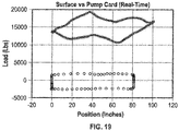
- we may skip a few surface data points so that we have enough time to execute the real-time diagnostic algorithm. For example, if we skip every two surface data points with the Fourier series method, we may have a real-time pump card as shown in Fig. 19 for the parameters as shown in Table 1.
- the surface data is synthesized from SROD.
- Fig. 19 shows that our real-time pump diagnostic algorithm is still valid even if every few surface data points are skipped.
- This disclosure addresses the issue o determining the "real" delay time of the real-time pump motion relative to the real-time polished rod motion.
- the disclosed method for determining the delay time may work for both the finite difference method and the Fourier series method. Both methods generate a similar motion delay time for the pump relative to the polished rod.
Landscapes
- Engineering & Computer Science (AREA)
- Life Sciences & Earth Sciences (AREA)
- Mining & Mineral Resources (AREA)
- Geology (AREA)
- Physics & Mathematics (AREA)
- Fluid Mechanics (AREA)
- Geophysics (AREA)
- Environmental & Geological Engineering (AREA)
- General Life Sciences & Earth Sciences (AREA)
- Geochemistry & Mineralogy (AREA)
- General Engineering & Computer Science (AREA)
- Mechanical Engineering (AREA)
- Computer Hardware Design (AREA)
- Control Of Positive-Displacement Pumps (AREA)
- Complex Calculations (AREA)
- Reciprocating Pumps (AREA)
Claims (6)
- Procédé pour générer une carte de pompe pour un puits, le procédé comprenant :a) l'obtention d'un premier ensemble de points de données, dans lequel le premier ensemble de points de données comprennent un premier ensemble de points de données de position de tige polie du puits et un premier ensemble de points de données de charge de tige polie du puits ;b) le calcul d'un premier point de données d'une charge de pompe et d'une position de pompe en utilisant le premier ensemble de points de données ;
et caractérisé en ce qu'il comprend :c) la suppression du point de données le plus ancien du premier ensemble de points de données pour créer un premier ensemble révisé de points de données ;d) l'obtention d'un point de données supplémentaire, dans lequel le point de données supplémentaire comprend un point de données de position de tige polie supplémentaire du puits et un point de données de charge de tige polie supplémentaire du puits ;e) la création d'un second ensemble de points de données, dans lequel le second ensemble de points de données comprend le premier ensemble révisé de points de données et le point de données supplémentaire ; etf) le calcul d'un point de données supplémentaire de la position de la pompe et de la charge de la pompe en utilisant le second ensemble de points de données. - Procédé selon la revendication 1, comprenant en outre :a) l'affichage du point de données supplémentaire ; etb) l'affichage en temps réel ou en temps quasi réel du premier point de données de la position de la pompe et de la charge de la pompe synchronisé avec l'affichage du point de données supplémentaire.
- Procédé selon la revendication 1, comprenant en outre le diagnostic de l'état du puits.
- Procédé selon la revendication 1, dans lequel le calcul comprend l'application d'un algorithme de série de Fourier.
- Procédé selon la revendication 1, comprenant en outre l'application d'une technique de temps de retard de propagation d'onde.
- Procédé selon la revendication 1, comprenant en outre l'arrêt de l'unité de pompage ou la modification de la vitesse de l'unité de pompage.
Applications Claiming Priority (3)
| Application Number | Priority Date | Filing Date | Title |
|---|---|---|---|
| US201261727894P | 2012-11-19 | 2012-11-19 | |
| PCT/US2013/070780 WO2014078851A2 (fr) | 2012-11-19 | 2013-11-19 | Algorithmes de diagnostic de pompe en temps réel et leur application |
| EP13811650.4A EP2920466B1 (fr) | 2012-11-19 | 2013-11-19 | Algorithmes de diagnostic de pompe en temps réel et leur application |
Related Parent Applications (2)
| Application Number | Title | Priority Date | Filing Date |
|---|---|---|---|
| EP13811650.4A Division-Into EP2920466B1 (fr) | 2012-11-19 | 2013-11-19 | Algorithmes de diagnostic de pompe en temps réel et leur application |
| EP13811650.4A Division EP2920466B1 (fr) | 2012-11-19 | 2013-11-19 | Algorithmes de diagnostic de pompe en temps réel et leur application |
Publications (2)
| Publication Number | Publication Date |
|---|---|
| EP3315775A1 EP3315775A1 (fr) | 2018-05-02 |
| EP3315775B1 true EP3315775B1 (fr) | 2020-02-12 |
Family
ID=49876970
Family Applications (2)
| Application Number | Title | Priority Date | Filing Date |
|---|---|---|---|
| EP17202438.2A Active EP3315775B1 (fr) | 2012-11-19 | 2013-11-19 | Algorithmes de diagnostic de pompe en temps réel et leur application |
| EP13811650.4A Active EP2920466B1 (fr) | 2012-11-19 | 2013-11-19 | Algorithmes de diagnostic de pompe en temps réel et leur application |
Family Applications After (1)
| Application Number | Title | Priority Date | Filing Date |
|---|---|---|---|
| EP13811650.4A Active EP2920466B1 (fr) | 2012-11-19 | 2013-11-19 | Algorithmes de diagnostic de pompe en temps réel et leur application |
Country Status (5)
| Country | Link |
|---|---|
| US (1) | US11639660B2 (fr) |
| EP (2) | EP3315775B1 (fr) |
| CN (1) | CN104956030B (fr) |
| CA (1) | CA2891575C (fr) |
| WO (1) | WO2014078851A2 (fr) |
Families Citing this family (10)
| Publication number | Priority date | Publication date | Assignee | Title |
|---|---|---|---|---|
| US10145230B2 (en) | 2014-10-10 | 2018-12-04 | Henry Research And Development, Llc | Systems and methods for real-time monitoring of downhole pump conditions |
| CN106321072B (zh) * | 2015-06-15 | 2019-02-19 | 中国科学院沈阳自动化研究所 | 一种基于泵功图的抽油井故障诊断方法 |
| US10408205B2 (en) * | 2016-08-04 | 2019-09-10 | Schneider Electric Systems Canada Inc. | Method of determining pump fill and adjusting speed of a rod pumping system |
| CN106321071B (zh) * | 2016-08-31 | 2020-04-21 | 中国石油集团东方地球物理勘探有限责任公司 | 一种抽油机生产参数优化方法 |
| CN106437682B (zh) * | 2016-11-01 | 2019-10-01 | 中国石油集团东方地球物理勘探有限责任公司 | 一种预测油井示功图的方法 |
| CN108678941B (zh) * | 2018-05-17 | 2019-10-22 | 中国石油大学(华东) | 一种悬点载荷频谱分析方法和装置 |
| CN112031748B (zh) * | 2020-09-14 | 2023-09-01 | 南京富岛信息工程有限公司 | 一种基于示功图特征的抽油机井异常工况诊断方法 |
| US11619225B2 (en) * | 2020-12-08 | 2023-04-04 | International Business Machines Corporation | Identifying potential problems in a pumpjack |
| US11898552B2 (en) * | 2021-08-16 | 2024-02-13 | Sk Innovation Co., Ltd. | Method and system for predicting failures of sucker rod pumps using scaled load ratios |
| US11898550B2 (en) * | 2022-02-28 | 2024-02-13 | Schneider Electric Systems Usa, Inc. | Progressing cavity pump control using pump fillage with PID based controller |
Family Cites Families (21)
| Publication number | Priority date | Publication date | Assignee | Title |
|---|---|---|---|---|
| US3998568A (en) * | 1975-05-27 | 1976-12-21 | Hynd Ike W | Pump-off control responsive to time changes between rod string load |
| CN87205901U (zh) | 1987-03-31 | 1988-04-20 | 西安交通大学 | 抽油井数字示功仪 |
| US5252031A (en) * | 1992-04-21 | 1993-10-12 | Gibbs Sam G | Monitoring and pump-off control with downhole pump cards |
| US5314016A (en) * | 1993-05-19 | 1994-05-24 | Shell Oil Company | Method for controlling rod-pumped wells |
| US5941305A (en) | 1998-01-29 | 1999-08-24 | Patton Enterprises, Inc. | Real-time pump optimization system |
| US6857474B2 (en) * | 2001-10-02 | 2005-02-22 | Lufkin Industries, Inc. | Methods, apparatus and products useful in the operation of a sucker rod pump during the production of hydrocarbons |
| AU2003254284A1 (en) * | 2002-08-01 | 2004-02-23 | Aware, Inc. | Multi-tap frequency domain equalization with decision feedback and trellis decoding |
| US20080240930A1 (en) | 2005-10-13 | 2008-10-02 | Pumpwell Solution Ltd | Method and System for Optimizing Downhole Fluid Production |
| US8136395B2 (en) | 2007-12-31 | 2012-03-20 | Schlumberger Technology Corporation | Systems and methods for well data analysis |
| US8157537B2 (en) | 2008-06-13 | 2012-04-17 | Petrolog Automation, Inc | Method, system, and apparatus for operating a sucker rod pump |
| US8036829B2 (en) * | 2008-10-31 | 2011-10-11 | Lufkin Industries, Inc. | Apparatus for analysis and control of a reciprocating pump system by determination of a pump card |
| US8306762B2 (en) * | 2010-01-25 | 2012-11-06 | Baker Hughes Incorporated | Systems and methods for analysis of downhole data |
| GB201005913D0 (en) * | 2010-04-09 | 2010-05-26 | Schlumberger Holdings | Method for real-time data compression and transmission |
| US8988236B2 (en) * | 2010-05-27 | 2015-03-24 | University Of Southern California | System and method for failure prediction for rod pump artificial lift systems |
| CN102337866A (zh) | 2010-07-21 | 2012-02-01 | 周玉姝 | 一种用于在油田抽油机中的节能控制方法及系统 |
| WO2012027633A2 (fr) * | 2010-08-26 | 2012-03-01 | Smith International, Inc. | Procédé de réduction de bruit de télémétrie par impulsion de boue |
| SK1692010A3 (sk) * | 2010-12-16 | 2012-07-03 | Naftamatika, S. R. O. | Method of diagnosis and management of pumping oil or gas wells and device there of |
| CN102094626A (zh) * | 2010-12-20 | 2011-06-15 | 中国石油天然气股份有限公司 | 油井故障实时预警方法和系统 |
| CA2744324C (fr) * | 2011-06-27 | 2018-10-16 | Pumpwell Solutions Ltd. | Systeme et methode pour determiner l'emplacement de la tige polie des pompes alternatives a tige |
| CN102402184B (zh) | 2011-10-28 | 2013-09-11 | 中国石油集团川庆钻探工程有限公司 | 井筒压力模型预测系统控制方法 |
| EP2771541B8 (fr) * | 2011-10-28 | 2017-09-20 | Weatherford Technology Holdings, LLC | Cartes de fond de puits pour le calcul dans des puits déviés |
-
2013
- 2013-11-19 WO PCT/US2013/070780 patent/WO2014078851A2/fr not_active Ceased
- 2013-11-19 US US14/443,878 patent/US11639660B2/en active Active
- 2013-11-19 EP EP17202438.2A patent/EP3315775B1/fr active Active
- 2013-11-19 EP EP13811650.4A patent/EP2920466B1/fr active Active
- 2013-11-19 CA CA2891575A patent/CA2891575C/fr active Active
- 2013-11-19 CN CN201380060375.0A patent/CN104956030B/zh active Active
Non-Patent Citations (1)
| Title |
|---|
| None * |
Also Published As
| Publication number | Publication date |
|---|---|
| EP2920466B1 (fr) | 2018-07-11 |
| US20150275651A1 (en) | 2015-10-01 |
| WO2014078851A3 (fr) | 2014-08-28 |
| EP3315775A1 (fr) | 2018-05-02 |
| CN104956030B (zh) | 2021-05-28 |
| WO2014078851A2 (fr) | 2014-05-22 |
| CN104956030A (zh) | 2015-09-30 |
| CA2891575C (fr) | 2021-06-29 |
| CA2891575A1 (fr) | 2014-05-22 |
| EP2920466A2 (fr) | 2015-09-23 |
| US11639660B2 (en) | 2023-05-02 |
Similar Documents
| Publication | Publication Date | Title |
|---|---|---|
| EP3315775B1 (fr) | Algorithmes de diagnostic de pompe en temps réel et leur application | |
| AU2012328426B2 (en) | Calculating downhole cards in deviated wells | |
| EP3176361B1 (fr) | Calcul d'une carte de fond de trou de forage dévié à l'aide de calculs de segment paramétrée | |
| Detournay et al. | Design charts for a deep circular tunnel under non-uniform loading | |
| US9239407B2 (en) | Injection treatment simulation using condensation | |
| US20140222393A1 (en) | Modeling Subterranean Rock Blocks In An Injection Treatment Simulation | |
| EA010456B1 (ru) | Способ, система и программное запоминающее устройство для моделирования многослойного пласта и частично активных элементов в программе моделирования гидравлического разрыва | |
| US10018032B2 (en) | Stress calculations for sucker rod pumping systems | |
| EP2963234B1 (fr) | Calculs de contrainte pour des systèmes de pompage à tige de pompage | |
| Saxena et al. | Effect of spatial variation of earthquake ground motion on the nonlinear dynamic response of highway bridges | |
| Yin et al. | A novel method for diagnosis of sucker-rod pumping systems based on the polished-rod load vibration in vertical wells | |
| US7063147B2 (en) | Method and apparatus and program storage device for front tracking in hydraulic fracturing simulators | |
| WO2014072445A2 (fr) | Procédé pour coupler des modèles d'écoulement de fluide et géomécanique pour systèmes de pétrole intégrés utilisant des événements de déclenchement connus | |
| Tezduyar et al. | Arterial fluid mechanics with the sequentially-coupled arterial FSI technique | |
| Wu et al. | Estimation of hydrodynamic coefficients for VIV of slender beam at high mode orders | |
| JP7089891B2 (ja) | 地盤の凍結膨張解析方法 | |
| Zhuravkov et al. | A coupled algorithm for numerical analysis of an undermined rock massif stress–strain state | |
| Sadovskii et al. | Modeling of fan waves taking into account the resistance to separation of domino-slabs in a fan-shaped system | |
| US20120215452A1 (en) | System and method for waterflood management | |
| Azad et al. | The role of geomechanical observation in continuous updating of thermal-recovery simulations with the Ensemble Kalman filter | |
| Shibing | Integration of Discrete Element Method and Time Series Analysis Technique to Predict Deformation in Blocky Rock Slopes | |
| Farag et al. | Second Order Inelastic Analysis of Steel Space Frames Subjected to Span Loads | |
| JP2006038455A (ja) | 有限要素法プログラムを用いた地盤の液状化解析法 | |
| Azad et al. | The Role of Geomechanical Observation in Continuous Updating of Thermal Recovery Simulations Using the Ensemble Kalman Filter | |
| Liu | Static Lagrangian method for analysis of continuum mechanical behaviors. |
Legal Events
| Date | Code | Title | Description |
|---|---|---|---|
| PUAI | Public reference made under article 153(3) epc to a published international application that has entered the european phase |
Free format text: ORIGINAL CODE: 0009012 |
|
| STAA | Information on the status of an ep patent application or granted ep patent |
Free format text: STATUS: THE APPLICATION HAS BEEN PUBLISHED |
|
| AC | Divisional application: reference to earlier application |
Ref document number: 2920466 Country of ref document: EP Kind code of ref document: P |
|
| AK | Designated contracting states |
Kind code of ref document: A1 Designated state(s): AL AT BE BG CH CY CZ DE DK EE ES FI FR GB GR HR HU IE IS IT LI LT LU LV MC MK MT NL NO PL PT RO RS SE SI SK SM TR |
|
| STAA | Information on the status of an ep patent application or granted ep patent |
Free format text: STATUS: REQUEST FOR EXAMINATION WAS MADE |
|
| 17P | Request for examination filed |
Effective date: 20181102 |
|
| RBV | Designated contracting states (corrected) |
Designated state(s): AL AT BE BG CH CY CZ DE DK EE ES FI FR GB GR HR HU IE IS IT LI LT LU LV MC MK MT NL NO PL PT RO RS SE SI SK SM TR |
|
| GRAP | Despatch of communication of intention to grant a patent |
Free format text: ORIGINAL CODE: EPIDOSNIGR1 |
|
| STAA | Information on the status of an ep patent application or granted ep patent |
Free format text: STATUS: GRANT OF PATENT IS INTENDED |
|
| INTG | Intention to grant announced |
Effective date: 20190402 |
|
| GRAS | Grant fee paid |
Free format text: ORIGINAL CODE: EPIDOSNIGR3 |
|
| GRAA | (expected) grant |
Free format text: ORIGINAL CODE: 0009210 |
|
| STAA | Information on the status of an ep patent application or granted ep patent |
Free format text: STATUS: THE PATENT HAS BEEN GRANTED |
|
| AC | Divisional application: reference to earlier application |
Ref document number: 2920466 Country of ref document: EP Kind code of ref document: P |
|
| AK | Designated contracting states |
Kind code of ref document: B1 Designated state(s): AL AT BE BG CH CY CZ DE DK EE ES FI FR GB GR HR HU IE IS IT LI LT LU LV MC MK MT NL NO PL PT RO RS SE SI SK SM TR |
|
| REG | Reference to a national code |
Ref country code: GB Ref legal event code: FG4D |
|
| REG | Reference to a national code |
Ref country code: CH Ref legal event code: EP |
|
| REG | Reference to a national code |
Ref country code: AT Ref legal event code: REF Ref document number: 1232453 Country of ref document: AT Kind code of ref document: T Effective date: 20200215 |
|
| REG | Reference to a national code |
Ref country code: IE Ref legal event code: FG4D |
|
| REG | Reference to a national code |
Ref country code: DE Ref legal event code: R096 Ref document number: 602013065873 Country of ref document: DE |
|
| REG | Reference to a national code |
Ref country code: NL Ref legal event code: FP |
|
| REG | Reference to a national code |
Ref country code: NO Ref legal event code: T2 Effective date: 20200212 |
|
| PG25 | Lapsed in a contracting state [announced via postgrant information from national office to epo] |
Ref country code: FI Free format text: LAPSE BECAUSE OF FAILURE TO SUBMIT A TRANSLATION OF THE DESCRIPTION OR TO PAY THE FEE WITHIN THE PRESCRIBED TIME-LIMIT Effective date: 20200212 Ref country code: RS Free format text: LAPSE BECAUSE OF FAILURE TO SUBMIT A TRANSLATION OF THE DESCRIPTION OR TO PAY THE FEE WITHIN THE PRESCRIBED TIME-LIMIT Effective date: 20200212 |
|
| REG | Reference to a national code |
Ref country code: LT Ref legal event code: MG4D |
|
| PG25 | Lapsed in a contracting state [announced via postgrant information from national office to epo] |
Ref country code: SE Free format text: LAPSE BECAUSE OF FAILURE TO SUBMIT A TRANSLATION OF THE DESCRIPTION OR TO PAY THE FEE WITHIN THE PRESCRIBED TIME-LIMIT Effective date: 20200212 Ref country code: LV Free format text: LAPSE BECAUSE OF FAILURE TO SUBMIT A TRANSLATION OF THE DESCRIPTION OR TO PAY THE FEE WITHIN THE PRESCRIBED TIME-LIMIT Effective date: 20200212 Ref country code: GR Free format text: LAPSE BECAUSE OF FAILURE TO SUBMIT A TRANSLATION OF THE DESCRIPTION OR TO PAY THE FEE WITHIN THE PRESCRIBED TIME-LIMIT Effective date: 20200513 Ref country code: HR Free format text: LAPSE BECAUSE OF FAILURE TO SUBMIT A TRANSLATION OF THE DESCRIPTION OR TO PAY THE FEE WITHIN THE PRESCRIBED TIME-LIMIT Effective date: 20200212 Ref country code: IS Free format text: LAPSE BECAUSE OF FAILURE TO SUBMIT A TRANSLATION OF THE DESCRIPTION OR TO PAY THE FEE WITHIN THE PRESCRIBED TIME-LIMIT Effective date: 20200612 Ref country code: BG Free format text: LAPSE BECAUSE OF FAILURE TO SUBMIT A TRANSLATION OF THE DESCRIPTION OR TO PAY THE FEE WITHIN THE PRESCRIBED TIME-LIMIT Effective date: 20200512 |
|
| PG25 | Lapsed in a contracting state [announced via postgrant information from national office to epo] |
Ref country code: ES Free format text: LAPSE BECAUSE OF FAILURE TO SUBMIT A TRANSLATION OF THE DESCRIPTION OR TO PAY THE FEE WITHIN THE PRESCRIBED TIME-LIMIT Effective date: 20200212 Ref country code: RO Free format text: LAPSE BECAUSE OF FAILURE TO SUBMIT A TRANSLATION OF THE DESCRIPTION OR TO PAY THE FEE WITHIN THE PRESCRIBED TIME-LIMIT Effective date: 20200212 Ref country code: PT Free format text: LAPSE BECAUSE OF FAILURE TO SUBMIT A TRANSLATION OF THE DESCRIPTION OR TO PAY THE FEE WITHIN THE PRESCRIBED TIME-LIMIT Effective date: 20200705 Ref country code: CZ Free format text: LAPSE BECAUSE OF FAILURE TO SUBMIT A TRANSLATION OF THE DESCRIPTION OR TO PAY THE FEE WITHIN THE PRESCRIBED TIME-LIMIT Effective date: 20200212 Ref country code: LT Free format text: LAPSE BECAUSE OF FAILURE TO SUBMIT A TRANSLATION OF THE DESCRIPTION OR TO PAY THE FEE WITHIN THE PRESCRIBED TIME-LIMIT Effective date: 20200212 Ref country code: DK Free format text: LAPSE BECAUSE OF FAILURE TO SUBMIT A TRANSLATION OF THE DESCRIPTION OR TO PAY THE FEE WITHIN THE PRESCRIBED TIME-LIMIT Effective date: 20200212 Ref country code: SM Free format text: LAPSE BECAUSE OF FAILURE TO SUBMIT A TRANSLATION OF THE DESCRIPTION OR TO PAY THE FEE WITHIN THE PRESCRIBED TIME-LIMIT Effective date: 20200212 Ref country code: EE Free format text: LAPSE BECAUSE OF FAILURE TO SUBMIT A TRANSLATION OF THE DESCRIPTION OR TO PAY THE FEE WITHIN THE PRESCRIBED TIME-LIMIT Effective date: 20200212 Ref country code: SK Free format text: LAPSE BECAUSE OF FAILURE TO SUBMIT A TRANSLATION OF THE DESCRIPTION OR TO PAY THE FEE WITHIN THE PRESCRIBED TIME-LIMIT Effective date: 20200212 |
|
| REG | Reference to a national code |
Ref country code: DE Ref legal event code: R097 Ref document number: 602013065873 Country of ref document: DE |
|
| REG | Reference to a national code |
Ref country code: AT Ref legal event code: MK05 Ref document number: 1232453 Country of ref document: AT Kind code of ref document: T Effective date: 20200212 |
|
| PLBE | No opposition filed within time limit |
Free format text: ORIGINAL CODE: 0009261 |
|
| STAA | Information on the status of an ep patent application or granted ep patent |
Free format text: STATUS: NO OPPOSITION FILED WITHIN TIME LIMIT |
|
| PGFP | Annual fee paid to national office [announced via postgrant information from national office to epo] |
Ref country code: NL Payment date: 20201113 Year of fee payment: 8 |
|
| 26N | No opposition filed |
Effective date: 20201113 |
|
| PG25 | Lapsed in a contracting state [announced via postgrant information from national office to epo] |
Ref country code: AT Free format text: LAPSE BECAUSE OF FAILURE TO SUBMIT A TRANSLATION OF THE DESCRIPTION OR TO PAY THE FEE WITHIN THE PRESCRIBED TIME-LIMIT Effective date: 20200212 Ref country code: IT Free format text: LAPSE BECAUSE OF FAILURE TO SUBMIT A TRANSLATION OF THE DESCRIPTION OR TO PAY THE FEE WITHIN THE PRESCRIBED TIME-LIMIT Effective date: 20200212 |
|
| PG25 | Lapsed in a contracting state [announced via postgrant information from national office to epo] |
Ref country code: SI Free format text: LAPSE BECAUSE OF FAILURE TO SUBMIT A TRANSLATION OF THE DESCRIPTION OR TO PAY THE FEE WITHIN THE PRESCRIBED TIME-LIMIT Effective date: 20200212 Ref country code: PL Free format text: LAPSE BECAUSE OF FAILURE TO SUBMIT A TRANSLATION OF THE DESCRIPTION OR TO PAY THE FEE WITHIN THE PRESCRIBED TIME-LIMIT Effective date: 20200212 |
|
| REG | Reference to a national code |
Ref country code: NO Ref legal event code: MMEP |
|
| PG25 | Lapsed in a contracting state [announced via postgrant information from national office to epo] |
Ref country code: MC Free format text: LAPSE BECAUSE OF FAILURE TO SUBMIT A TRANSLATION OF THE DESCRIPTION OR TO PAY THE FEE WITHIN THE PRESCRIBED TIME-LIMIT Effective date: 20200212 |
|
| REG | Reference to a national code |
Ref country code: CH Ref legal event code: PL |
|
| PG25 | Lapsed in a contracting state [announced via postgrant information from national office to epo] |
Ref country code: LU Free format text: LAPSE BECAUSE OF NON-PAYMENT OF DUE FEES Effective date: 20201119 Ref country code: NO Free format text: LAPSE BECAUSE OF NON-PAYMENT OF DUE FEES Effective date: 20201130 |
|
| REG | Reference to a national code |
Ref country code: BE Ref legal event code: MM Effective date: 20201130 |
|
| PG25 | Lapsed in a contracting state [announced via postgrant information from national office to epo] |
Ref country code: LI Free format text: LAPSE BECAUSE OF NON-PAYMENT OF DUE FEES Effective date: 20201130 Ref country code: CH Free format text: LAPSE BECAUSE OF NON-PAYMENT OF DUE FEES Effective date: 20201130 |
|
| PG25 | Lapsed in a contracting state [announced via postgrant information from national office to epo] |
Ref country code: FR Free format text: LAPSE BECAUSE OF NON-PAYMENT OF DUE FEES Effective date: 20201130 Ref country code: IE Free format text: LAPSE BECAUSE OF NON-PAYMENT OF DUE FEES Effective date: 20201119 |
|
| PG25 | Lapsed in a contracting state [announced via postgrant information from national office to epo] |
Ref country code: TR Free format text: LAPSE BECAUSE OF FAILURE TO SUBMIT A TRANSLATION OF THE DESCRIPTION OR TO PAY THE FEE WITHIN THE PRESCRIBED TIME-LIMIT Effective date: 20200212 Ref country code: MT Free format text: LAPSE BECAUSE OF FAILURE TO SUBMIT A TRANSLATION OF THE DESCRIPTION OR TO PAY THE FEE WITHIN THE PRESCRIBED TIME-LIMIT Effective date: 20200212 Ref country code: CY Free format text: LAPSE BECAUSE OF FAILURE TO SUBMIT A TRANSLATION OF THE DESCRIPTION OR TO PAY THE FEE WITHIN THE PRESCRIBED TIME-LIMIT Effective date: 20200212 |
|
| PG25 | Lapsed in a contracting state [announced via postgrant information from national office to epo] |
Ref country code: MK Free format text: LAPSE BECAUSE OF FAILURE TO SUBMIT A TRANSLATION OF THE DESCRIPTION OR TO PAY THE FEE WITHIN THE PRESCRIBED TIME-LIMIT Effective date: 20200212 Ref country code: AL Free format text: LAPSE BECAUSE OF FAILURE TO SUBMIT A TRANSLATION OF THE DESCRIPTION OR TO PAY THE FEE WITHIN THE PRESCRIBED TIME-LIMIT Effective date: 20200212 |
|
| REG | Reference to a national code |
Ref country code: NL Ref legal event code: MM Effective date: 20211201 |
|
| PG25 | Lapsed in a contracting state [announced via postgrant information from national office to epo] |
Ref country code: BE Free format text: LAPSE BECAUSE OF NON-PAYMENT OF DUE FEES Effective date: 20201130 |
|
| PG25 | Lapsed in a contracting state [announced via postgrant information from national office to epo] |
Ref country code: NL Free format text: LAPSE BECAUSE OF NON-PAYMENT OF DUE FEES Effective date: 20211201 |
|
| REG | Reference to a national code |
Ref country code: GB Ref legal event code: 732E Free format text: REGISTERED BETWEEN 20230602 AND 20230607 |
|
| REG | Reference to a national code |
Ref country code: DE Ref legal event code: R081 Ref document number: 602013065873 Country of ref document: DE Owner name: RAVDOS HOLDINGS INC. (N.D.GES.D.STAATES DELAWA, US Free format text: FORMER OWNER: LUFKIN INDUSTRIES, LLC, LUFKIN, TEX., US Ref country code: DE Ref legal event code: R082 Ref document number: 602013065873 Country of ref document: DE Representative=s name: DENTONS PATENT SOLUTIONS RECHTSANWALTSGESELLSC, DE |
|
| P01 | Opt-out of the competence of the unified patent court (upc) registered |
Effective date: 20230620 |
|
| PGFP | Annual fee paid to national office [announced via postgrant information from national office to epo] |
Ref country code: DE Payment date: 20251022 Year of fee payment: 13 |
|
| PGFP | Annual fee paid to national office [announced via postgrant information from national office to epo] |
Ref country code: GB Payment date: 20251023 Year of fee payment: 13 |