EP3315847B1 - Led-suchlicht und verfahren - Google Patents
Led-suchlicht und verfahren Download PDFInfo
- Publication number
- EP3315847B1 EP3315847B1 EP17198163.2A EP17198163A EP3315847B1 EP 3315847 B1 EP3315847 B1 EP 3315847B1 EP 17198163 A EP17198163 A EP 17198163A EP 3315847 B1 EP3315847 B1 EP 3315847B1
- Authority
- EP
- European Patent Office
- Prior art keywords
- housing portion
- heat sink
- searchlight
- reflector
- flow path
- Prior art date
- Legal status (The legal status is an assumption and is not a legal conclusion. Google has not performed a legal analysis and makes no representation as to the accuracy of the status listed.)
- Not-in-force
Links
Images


Classifications
-
- B—PERFORMING OPERATIONS; TRANSPORTING
- B60—VEHICLES IN GENERAL
- B60Q—ARRANGEMENT OF SIGNALLING OR LIGHTING DEVICES, THE MOUNTING OR SUPPORTING THEREOF OR CIRCUITS THEREFOR, FOR VEHICLES IN GENERAL
- B60Q1/00—Arrangement of optical signalling or lighting devices, the mounting or supporting thereof or circuits therefor
- B60Q1/02—Arrangement of optical signalling or lighting devices, the mounting or supporting thereof or circuits therefor the devices being primarily intended to illuminate the way ahead or to illuminate other areas of way or environments
- B60Q1/24—Arrangement of optical signalling or lighting devices, the mounting or supporting thereof or circuits therefor the devices being primarily intended to illuminate the way ahead or to illuminate other areas of way or environments for lighting other areas than only the way ahead
- B60Q1/245—Searchlights, e.g. adjustable from within the vehicle
-
- F—MECHANICAL ENGINEERING; LIGHTING; HEATING; WEAPONS; BLASTING
- F21—LIGHTING
- F21V—FUNCTIONAL FEATURES OR DETAILS OF LIGHTING DEVICES OR SYSTEMS THEREOF; STRUCTURAL COMBINATIONS OF LIGHTING DEVICES WITH OTHER ARTICLES, NOT OTHERWISE PROVIDED FOR
- F21V23/00—Arrangement of electric circuit elements in or on lighting devices
-
- B—PERFORMING OPERATIONS; TRANSPORTING
- B64—AIRCRAFT; AVIATION; COSMONAUTICS
- B64D—EQUIPMENT FOR FITTING IN OR TO AIRCRAFT; FLIGHT SUITS; PARACHUTES; ARRANGEMENT OR MOUNTING OF POWER PLANTS OR PROPULSION TRANSMISSIONS IN AIRCRAFT
- B64D47/00—Equipment not otherwise provided for
- B64D47/02—Arrangements or adaptations of signal or lighting devices
-
- F—MECHANICAL ENGINEERING; LIGHTING; HEATING; WEAPONS; BLASTING
- F21—LIGHTING
- F21S—NON-PORTABLE LIGHTING DEVICES; SYSTEMS THEREOF; VEHICLE LIGHTING DEVICES SPECIALLY ADAPTED FOR VEHICLE EXTERIORS
- F21S8/00—Lighting devices intended for fixed installation
- F21S8/003—Searchlights, i.e. outdoor lighting device producing powerful beam of parallel rays, e.g. for military or attraction purposes
-
- F—MECHANICAL ENGINEERING; LIGHTING; HEATING; WEAPONS; BLASTING
- F21—LIGHTING
- F21V—FUNCTIONAL FEATURES OR DETAILS OF LIGHTING DEVICES OR SYSTEMS THEREOF; STRUCTURAL COMBINATIONS OF LIGHTING DEVICES WITH OTHER ARTICLES, NOT OTHERWISE PROVIDED FOR
- F21V29/00—Protecting lighting devices from thermal damage; Cooling or heating arrangements specially adapted for lighting devices or systems
- F21V29/50—Cooling arrangements
- F21V29/502—Cooling arrangements characterised by the adaptation for cooling of specific components
- F21V29/503—Cooling arrangements characterised by the adaptation for cooling of specific components of light sources
-
- F—MECHANICAL ENGINEERING; LIGHTING; HEATING; WEAPONS; BLASTING
- F21—LIGHTING
- F21V—FUNCTIONAL FEATURES OR DETAILS OF LIGHTING DEVICES OR SYSTEMS THEREOF; STRUCTURAL COMBINATIONS OF LIGHTING DEVICES WITH OTHER ARTICLES, NOT OTHERWISE PROVIDED FOR
- F21V29/00—Protecting lighting devices from thermal damage; Cooling or heating arrangements specially adapted for lighting devices or systems
- F21V29/50—Cooling arrangements
- F21V29/502—Cooling arrangements characterised by the adaptation for cooling of specific components
- F21V29/508—Cooling arrangements characterised by the adaptation for cooling of specific components of electrical circuits
-
- F—MECHANICAL ENGINEERING; LIGHTING; HEATING; WEAPONS; BLASTING
- F21—LIGHTING
- F21V—FUNCTIONAL FEATURES OR DETAILS OF LIGHTING DEVICES OR SYSTEMS THEREOF; STRUCTURAL COMBINATIONS OF LIGHTING DEVICES WITH OTHER ARTICLES, NOT OTHERWISE PROVIDED FOR
- F21V29/00—Protecting lighting devices from thermal damage; Cooling or heating arrangements specially adapted for lighting devices or systems
- F21V29/50—Cooling arrangements
- F21V29/70—Cooling arrangements characterised by passive heat-dissipating elements, e.g. heat-sinks
- F21V29/71—Cooling arrangements characterised by passive heat-dissipating elements, e.g. heat-sinks using a combination of separate elements interconnected by heat-conducting means, e.g. with heat pipes or thermally conductive bars between separate heat-sink elements
-
- F—MECHANICAL ENGINEERING; LIGHTING; HEATING; WEAPONS; BLASTING
- F21—LIGHTING
- F21V—FUNCTIONAL FEATURES OR DETAILS OF LIGHTING DEVICES OR SYSTEMS THEREOF; STRUCTURAL COMBINATIONS OF LIGHTING DEVICES WITH OTHER ARTICLES, NOT OTHERWISE PROVIDED FOR
- F21V29/00—Protecting lighting devices from thermal damage; Cooling or heating arrangements specially adapted for lighting devices or systems
- F21V29/50—Cooling arrangements
- F21V29/70—Cooling arrangements characterised by passive heat-dissipating elements, e.g. heat-sinks
- F21V29/71—Cooling arrangements characterised by passive heat-dissipating elements, e.g. heat-sinks using a combination of separate elements interconnected by heat-conducting means, e.g. with heat pipes or thermally conductive bars between separate heat-sink elements
- F21V29/717—Cooling arrangements characterised by passive heat-dissipating elements, e.g. heat-sinks using a combination of separate elements interconnected by heat-conducting means, e.g. with heat pipes or thermally conductive bars between separate heat-sink elements using split or remote units thermally interconnected, e.g. by thermally conductive bars or heat pipes
-
- F—MECHANICAL ENGINEERING; LIGHTING; HEATING; WEAPONS; BLASTING
- F21—LIGHTING
- F21V—FUNCTIONAL FEATURES OR DETAILS OF LIGHTING DEVICES OR SYSTEMS THEREOF; STRUCTURAL COMBINATIONS OF LIGHTING DEVICES WITH OTHER ARTICLES, NOT OTHERWISE PROVIDED FOR
- F21V29/00—Protecting lighting devices from thermal damage; Cooling or heating arrangements specially adapted for lighting devices or systems
- F21V29/50—Cooling arrangements
- F21V29/70—Cooling arrangements characterised by passive heat-dissipating elements, e.g. heat-sinks
- F21V29/74—Cooling arrangements characterised by passive heat-dissipating elements, e.g. heat-sinks with fins or blades
- F21V29/76—Cooling arrangements characterised by passive heat-dissipating elements, e.g. heat-sinks with fins or blades with essentially identical parallel planar fins or blades, e.g. with comb-like cross-section
- F21V29/767—Cooling arrangements characterised by passive heat-dissipating elements, e.g. heat-sinks with fins or blades with essentially identical parallel planar fins or blades, e.g. with comb-like cross-section the planes containing the fins or blades having directions perpendicular to the light emitting axis
-
- F—MECHANICAL ENGINEERING; LIGHTING; HEATING; WEAPONS; BLASTING
- F21—LIGHTING
- F21V—FUNCTIONAL FEATURES OR DETAILS OF LIGHTING DEVICES OR SYSTEMS THEREOF; STRUCTURAL COMBINATIONS OF LIGHTING DEVICES WITH OTHER ARTICLES, NOT OTHERWISE PROVIDED FOR
- F21V29/00—Protecting lighting devices from thermal damage; Cooling or heating arrangements specially adapted for lighting devices or systems
- F21V29/50—Cooling arrangements
- F21V29/70—Cooling arrangements characterised by passive heat-dissipating elements, e.g. heat-sinks
- F21V29/83—Cooling arrangements characterised by passive heat-dissipating elements, e.g. heat-sinks the elements having apertures, ducts or channels, e.g. heat radiation holes
-
- B—PERFORMING OPERATIONS; TRANSPORTING
- B64—AIRCRAFT; AVIATION; COSMONAUTICS
- B64D—EQUIPMENT FOR FITTING IN OR TO AIRCRAFT; FLIGHT SUITS; PARACHUTES; ARRANGEMENT OR MOUNTING OF POWER PLANTS OR PROPULSION TRANSMISSIONS IN AIRCRAFT
- B64D2203/00—Aircraft or airfield lights using LEDs
-
- F—MECHANICAL ENGINEERING; LIGHTING; HEATING; WEAPONS; BLASTING
- F21—LIGHTING
- F21W—INDEXING SCHEME ASSOCIATED WITH SUBCLASSES F21K, F21L, F21S and F21V, RELATING TO USES OR APPLICATIONS OF LIGHTING DEVICES OR SYSTEMS
- F21W2131/00—Use or application of lighting devices or systems not provided for in codes F21W2102/00-F21W2121/00
- F21W2131/40—Lighting for industrial, commercial, recreational or military use
- F21W2131/406—Lighting for industrial, commercial, recreational or military use for theatres, stages or film studios
-
- F—MECHANICAL ENGINEERING; LIGHTING; HEATING; WEAPONS; BLASTING
- F21—LIGHTING
- F21Y—INDEXING SCHEME ASSOCIATED WITH SUBCLASSES F21K, F21L, F21S and F21V, RELATING TO THE FORM OR THE KIND OF THE LIGHT SOURCES OR OF THE COLOUR OF THE LIGHT EMITTED
- F21Y2115/00—Light-generating elements of semiconductor light sources
- F21Y2115/10—Light-emitting diodes [LED]
Definitions
- the technical field generally relates to search lights as are often found on aircraft and other search and rescue vehicles, and in particular, to a LED-based searchlight having a cooling efficient housing and heat sink structure and a method of cooling a searchlight.
- Searchlights are frequently used on search and rescue vehicles including search and rescue aircraft, such as helicopters, to illuminate areas of interest to the aircraft pilot and/or crew.
- searchlight designs including halogen / incandescent tungsten filament designs.
- these designs will often include multiple illumination sources adjacent a reflector and disposed within a housing covered with a glass or plastic lens.
- LEDs light emitting diodes
- searchlights An application where high power density light emitting diodes (LEDs) might provide a good design solution is searchlights.
- LED technology permits ever brighter constructions than existing incandescent technologies.
- the power or light output of an LED may be increased by increasing the die size. This allows still brighter LED arrays with fewer LED elements.
- Increasing die size to increase light output increases the power density of the LED, which also consolidates heat generation and complicates cooling requirements.
- US2011/285292 discloses exterior architectural fixtures that use high-intensity LED light sources for illuminating large structures, that uses separate heat sinks for each lighting unit to provide improved hear dissipation properties.
- US2013/088864 discloses a modular angled street light fixture that includes a central portion for connect the interlocking modular lighting units together, with separate heat sinks for each unit.
- a searchlight has a first housing portion and a second housing portion, wherein each of the first housing portion and the second housing portion has operably secured to form a reflector cavity, a heat sink, a reflector and a lens.
- the first housing portion and the second housing portion are joined to form a housing assembly.
- the first housing portion heat sink and the second housing portion heat sink are disposed adjacent to one another and form a cooling medium flow path there between, and the heat sink elements of each heat sink thermally communicate with the flow path.
- a first LED is directly thermally coupled to the heat sink within the first housing portion reflector cavity and a second LED is directly thermally coupled to the heat sink within the second housing portion reflector cavity.
- the searchlight is characterized by comprising a circuit/wiring block disposed within the heat sink defined flow path and mechanically joining the first housing portion heat sink and the second housing portion heat sink.
- Claim 8 defines a method of forming the searchlight of claim 1.
- system or “module” may refer to any combination or collection of mechanical and electrical hardware, software, firmware, electronic control component, processing logic, and/or processor device, individually or in any combination, including without limitation: application specific integrated circuit (ASIC), an electronic circuit, a processor (shared, dedicated, or group), memory that executes one or more software or firmware programs, a combinational logic circuit, and/or other suitable components that provide the described functionality.
- ASIC application specific integrated circuit
- processor shared, dedicated, or group
- memory executes one or more software or firmware programs, a combinational logic circuit, and/or other suitable components that provide the described functionality.
- Embodiments of a searchlight and method of forming the same may be described herein in terms of functional and/or logical block components and various processing steps. It should be appreciated that such block components may be realized by any number, combination or collection of mechanical and electrical hardware, software, and/or firmware components configured to perform the specified functions. For example, an embodiment may employ various combinations of electrical components, e.g., sensors, integrated circuit components, memory elements, digital signal processing elements, logic elements, look-up tables, or the like, which may carry out a variety of functions under the control of one or more microprocessors or other control devices.
- electrical components e.g., sensors, integrated circuit components, memory elements, digital signal processing elements, logic elements, look-up tables, or the like, which may carry out a variety of functions under the control of one or more microprocessors or other control devices.
- embodiments may be practiced in conjunction with any number of mechanical and/or electronic systems, and that the systems described herein are merely exemplary embodiments.
- An LED based searchlight in accordance with the herein described embodiments incorporates an LED device directly attached to a heat sink with no intermediate metal core or glass-reinforced epoxy laminate circuit card.
- a searchlight according to the herein described embodiments further uses housing portions of the searchlight for additional heat dissipation.
- the searchlight housing is uniquely formed to expose a heat sink and housing structure to a flow of cooling medium.
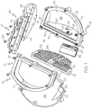
- a searchlight 10 includes a housing structure 12 including a cooling medium flow path 14.
- the housing structure 12 includes a first housing section 16 and a second housing section 18. It will be appreciated that in accordance with the herein described embodiments, the first housing section 16 and the second housing section 18 are symmetric to each other. The following discussion of the first housing section 16 is exemplary, and it will be understood that the second housing section 18 is generally identical but not symmetric. Like reference numerals are used to identify like, symmetrical elements between the first and second housing sections 16 and 18.
- the first housing section 16 includes a reflector 20, a heat sink 22 and a lens 24.
- the reflector 20 and the heat sink 22 are operably joined to form a reflector cavity 26.
- the reflector 20 and the heat sink 22 may be operably joined by bonding, welding, fastening and/or the like.
- the lens 24 is secured to the reflector 20 and the heat sink 22 by fasteners (one of which is indicated as fastener 28), although the lens could be otherwise secured to the reflector 20 and the heat sink 22. Removable fastening of the lens 24 permits removal of the lens 24 for servicing of components disposed within the reflector cavity 26.
- the joining of the reflector 20, the heat sink 22 and the lens 24 is accomplished in a way to ensure the reflector cavity is weather-tight, as it is intended that the searchlight 10 will be used in all weather conditions.
- the heat sink 22 may be made of a suitable low thermal resistance material, such as aluminum, aluminum alloys, metal, metal alloys, thermally conductive polymers and the like.
- the heat sink 22 has a cavity side surface 30 and a fin side surface 32.
- the cavity side surface 30 may be made reflective by polishing, by application of a reflective coating or by any suitable method.
- the fin side surface 32 is formed to include a plurality of heat dissipating elements, such as cooling fins 34, or other suitable structures that enhance the dissipation of heat from the heat sink 22 under the flow of a cooling media.
- the cooling fins advantageously extend into the cooling medium flow path 14.
- the first housing section 16 and the second housing section 18 are joined by a third housing section 40 and by a wiring / circuit block 42.
- the third housing section 40 is of similar construction as the first and second housing sections 16 and 18, and includes a reflector 44, a heat sink 46 and a lens 48 enclosing a reflector cavity 50 and secured by threaded fastener (one of which is indicated as fastener 52).
- the heat sink 46 suitably mechanically joins the first housing section 16 and the second housing section 18 such as engaging the respective heat sinks 22 by suitable fasteners (not depicted) extending through apertures 51.
- a circuit / wiring block 42 is disposed between and secures to the heat sinks 22 and 32.
- portions of the fins 34 may be removed forming a recess 54 into which the circuit / wiring block 42 is fitted and is secured, such as by threaded fasteners (one of which is indicated as fastener 53).
- the circuit / wiring block 42 is thereby advantageously disposed within the flow path 14 as well as being in thermal communication with the heat sinks 22 to ensure cooling of LED driver and other circuity (not depicted) disposed therein.
- the LED device 56 may be a single LED, an array of LED devices, a single die formed with multiple LED elements, or similar structures.
- the LED device 56 may emit light in the visible spectrum, the infrared spectrum, other spectrums visible or invisible and combinations thereof.
- the LED device 56 is in direct thermal contact with the cavity side surface 30, and hence to the heat sink 22. Heat from the LED device 56 is efficiently transferred from LED device 56 to the heat sink 22. From the cavity side surface 30, heat is communicated through the heat sink 22, which has low thermal resistance, to the fin side surface 32, which in operation is exposed to cooling medium passing through the flow path 14.
- the heat sink 22 is formed with a via (not depicted) through which a wiring connection from the LED device 56 is made to the wiring / circuit block 42.
- the reflectors 20 formed with a depression 58 and the circuit / wiring block 42 is formed with an external wiring coupling surface 60 ( Fig. 3 ) by which connections to external wiring may be made.
- the heat sinks 22 are further formed with a passage or via 64 through which a wiring connection is made from the third housing section 40, which may be an infrared housing section, to the circuit / wiring block 42.
- the reflectors 20 may be constructed of low thermal resistance material, such as aluminum, aluminum alloys, thermally conductive polymers and the like. When so constructed, the reflectors 20, being exposed to the environment during use of the searchlight 10, also contribute to heat dissipation.
- the cavity side surface 30 cooperates with a reflector surface 62 of the reflector 20 to optimize reflected light output of the searchlight 10.
- the reflector surface 62 may be made by polishing, providing a reflective coating and the like. Attaching the LED device 56 directly to the heat sink 22 eliminates the traditional circuit card to which LEDs are often attached. This allows more space within the reflector cavity 26 to be used for reflector area, i.e., the cavity side surface 30 and the reflector surface 62. Increasing the reflector area available to the LED device 56 improves illumination. Eliminating a circuit card or similar structure from within the reflector cavity 26 eliminates the thermal resistance offered by the circuit card to heat transfer from the LED device 56 to the heat sink 22. In addition to lowering the resistance to heat transfer by eliminating the circuit card, the flow path 14 allows for the heat sink 22 to be directly exposed to a flow of cooling medium so the LED device 56 can be cooled as efficiently as possible.
- the searchlight 10 provides for directly exposing the reflector 20 and heat sink 22 to the environment. This is made possible by splitting the search light into at least the first housing portion 16 and the second housing portion 18. Splitting the searchlight 10 into multiple portions allows for the formation of air flow paths, allowing airflow to pass directly over the heat sink 22 where the greatest heat flux exists, and cooling the LED device 56 at an increased rate.
- Embodiments described herein facilitate the use of high power LED device that will allow comparable illumination levels to existing searchlight constructions.
- Use of heat sinks and reflectors as heat sinks provide an increase in the mass of the heat sink capacity as well as increase in heat sink area.
Landscapes
- Engineering & Computer Science (AREA)
- General Engineering & Computer Science (AREA)
- Mechanical Engineering (AREA)
- Aviation & Aerospace Engineering (AREA)
- Arrangement Of Elements, Cooling, Sealing, Or The Like Of Lighting Devices (AREA)
Claims (8)
- Suchlicht (10), das aufweist:einen ersten Gehäuseabschnitt (16) und einen zweiten Gehäuseabschnitt (18), wobei jeder des ersten Gehäuseabschnitts (16) und des zweiten Gehäuseabschnitts (18) betriebsfähig befestigt Folgendes umfasst, um einen Reflektorhohlraum (26) zu bilden: einen Kühlkörper (22), einen Reflektor (20) und eine Linse (24);wobei der erste Gehäuseabschnitt (16) und der zweite Gehäuseabschnitt (18) verbunden sind, um eine Gehäuseanordnung zu bilden, wobei der erste Gehäuseabschnitt-Kühlkörper (22) und der zweite Gehäuseabschnitt-Kühlkörper (22) benachbart zueinander angeordnet sind und dazwischen einen Kühlmediumströmungsweg (14) bilden, so dass Kühlkörperelemente jedes Kühlkörpers (22) thermisch mit dem Strömungsweg (14) kommunizieren;eine erste LED-Vorrichtung (56), die direkt thermisch mit dem Kühlkörper (22) innerhalb des ersten Gehäuseabschnitt-Reflektorhohlraums (26) gekoppelt ist, und eine zweite LED-Vorrichtung (56), die direkt thermisch mit dem Kühlkörper innerhalb des zweiten Gehäuseabschnitt-Reflektorhohlraums gekoppelt ist (26), dadurch gekennzeichnet, dass das Suchlicht umfasst;einen Schaltungs-/Verdrahtungsblock (42), der innerhalb des Strömungswegs (14), der durch den Kühlkörper definiert ist, angeordnet ist und den ersten Gehäuseabschnitt-Kühlkörper (22) und den zweiten Gehäuseabschnitt-Kühlkörper (22) mechanisch verbindet.
- Suchlicht nach Anspruch 1, wobei sich die Kühlkörperelemente in dem Strömungsweg (14) erstrecken.
- Suchlicht nach Anspruch 1, das einen dritten Gehäuseabschnitt (40) umfasst, der den ersten Gehäuseabschnitt (16) und den zweiten Gehäuseabschnitt (18) verbindet.
- Suchlicht nach Anspruch 3, wobei der dritte Gehäuseabschnitt (40) betriebsfähig befestigt Folgendes umfasst, um einen dritten Reflektorhohlraum (50) zu bilden: einen Kühlkörper (46), einen Reflektor (44) und eine Linse (48) und eine dritte LED-Vorrichtung (56), wobei die dritte LED-Vorrichtung (56) innerhalb des dritten Reflektorhohlraums (50) angeordnet ist.
- Suchlicht nach Anspruch 1, wobei das Suchlicht Licht im sichtbaren oder infraroten Spektrum emittiert.
- Suchlicht nach Anspruch 1, wobei die Reflektoren (20) einen niedrigen Wärmewiderstand aufweisen.
- Suchlicht nach Anspruch 1, wobei die erste oder zweite LED-Vorrichtung (56) an einer reflektierenden Oberfläche des Kühlkörpers (22) befestigt ist.
- Verfahren zum Bilden des Suchlichts nach Anspruch 1, wobei das Suchlicht ein Suchlicht (10) umfasst, das einen ersten Gehäuseabschnitt (16) und einen zweiten Gehäuseabschnitt (18) aufweist, wobei der erste Gehäuseabschnitt (16) und der zweite Gehäuseabschnitt (18) betriebsfähig befestigt Folgendes umfassen, um einen Reflektorhohlraum (26) zu bilden:
einen Kühlkörper (22), einen Reflektor (20), einen Schaltungs-/Verdrahtungsblock (42) und eine Linse (24); wobei das Verfahren die Schritte umfasst:Einrichten der Kühlkörper (22), um dazwischen einen Kühlmediumströmungsweg (14) zu bilden,Befestigen einer LED-Vorrichtung (56) an dem Kühlkörper (22) innerhalb jedes der jeweiligen Reflektorhohlräume (26), unddadurch gekennzeichnet, dass das Verfahren das Anordnen des Schaltungs-/Verdrahtungsblocks innerhalb des Strömungswegs (14), der von dem Kühlkörper definiert wird, und das mechanische Verbinden des ersten Gehäuseabschnitt-Kühlkörpers (22) und des zweiten Gehäuseabschnitt-Kühlkörpers (22) beinhaltet.
Applications Claiming Priority (1)
| Application Number | Priority Date | Filing Date | Title |
|---|---|---|---|
| US15/339,134 US10180246B2 (en) | 2016-10-31 | 2016-10-31 | LED searchlight and method |
Publications (2)
| Publication Number | Publication Date |
|---|---|
| EP3315847A1 EP3315847A1 (de) | 2018-05-02 |
| EP3315847B1 true EP3315847B1 (de) | 2020-12-30 |
Family
ID=60190613
Family Applications (1)
| Application Number | Title | Priority Date | Filing Date |
|---|---|---|---|
| EP17198163.2A Not-in-force EP3315847B1 (de) | 2016-10-31 | 2017-10-24 | Led-suchlicht und verfahren |
Country Status (3)
| Country | Link |
|---|---|
| US (1) | US10180246B2 (de) |
| EP (1) | EP3315847B1 (de) |
| CN (1) | CN108019711A (de) |
Families Citing this family (5)
| Publication number | Priority date | Publication date | Assignee | Title |
|---|---|---|---|---|
| KR102271559B1 (ko) * | 2016-11-21 | 2021-07-01 | 저지앙 리 성 포토일렉트릭 테크놀로지 컴퍼니 리미티드 | Led 방열 구조 및 해당 방열 구조가 포함된 led 등기구 |
| US11192494B2 (en) | 2020-02-07 | 2021-12-07 | Honeywell International Inc. | Systems and methods for search and landing light |
| EP3882161B1 (de) | 2020-03-20 | 2023-08-16 | Goodrich Lighting Systems GmbH & Co. KG | Hubschraubersuchlicht und verfahren zum betrieb eines hubschraubersuchlichts |
| US11543115B1 (en) | 2021-06-18 | 2023-01-03 | Goodrich Corporation | Heat dissipating light assembly |
| US12222095B1 (en) * | 2023-05-26 | 2025-02-11 | Light & Motion Industries | Lightweight powerful LED light for drones |
Citations (2)
| Publication number | Priority date | Publication date | Assignee | Title |
|---|---|---|---|---|
| US20110285292A1 (en) * | 2007-12-22 | 2011-11-24 | Philips Solid-State Lighting Solutions, Inc. | Led-based luminaires for large-scale architectural illumination |
| US20130088864A1 (en) * | 2011-10-05 | 2013-04-11 | Anthony Verdes | Angled street light fixture |
Family Cites Families (31)
| Publication number | Priority date | Publication date | Assignee | Title |
|---|---|---|---|---|
| US5695272A (en) | 1994-05-27 | 1997-12-09 | Grimes Aerospace Company | Search light for aircraft and other vehicles |
| US6609812B2 (en) | 2000-12-20 | 2003-08-26 | Honeywell International Inc. | Dual mode visible and infrared lighthead |
| US6962423B2 (en) | 2001-11-06 | 2005-11-08 | Honeywell International Inc. | Multi-mode searchlight |
| EP1738400A2 (de) * | 2004-04-15 | 2007-01-03 | Koninklijke Philips Electronics N.V. | Lampeneinheit |
| CN1956668B (zh) * | 2004-05-26 | 2012-02-29 | 吉尔科有限公司 | 用于产品陈列柜的led照明系统 |
| US7771086B2 (en) * | 2004-07-27 | 2010-08-10 | Koninklijke Philips Electronics N.V. | Lighting device comprising a lamp unit a reflector |
| US7593229B2 (en) * | 2006-03-31 | 2009-09-22 | Hong Kong Applied Science & Technology Research Institute Co. Ltd | Heat exchange enhancement |
| US20070279862A1 (en) | 2006-06-06 | 2007-12-06 | Jia-Hao Li | Heat-Dissipating Structure For Lamp |
| US7518133B2 (en) | 2006-10-30 | 2009-04-14 | Honeywell International Inc. | Integrated searchlight lighthead |
| US7824056B2 (en) * | 2006-12-29 | 2010-11-02 | Hussmann Corporation | Refrigerated merchandiser with LED lighting |
| CN101329054B (zh) * | 2007-06-22 | 2010-09-29 | 富准精密工业(深圳)有限公司 | 具有散热结构的发光二极管灯具 |
| US7434964B1 (en) * | 2007-07-12 | 2008-10-14 | Fu Zhun Precision Industry (Shen Zhen) Co., Ltd. | LED lamp with a heat sink assembly |
| WO2009012245A2 (en) * | 2007-07-12 | 2009-01-22 | Sunovia Energy Technologies, Inc. | Solid state light unit and heat sink, and method for thermal management of a solid state light unit |
| US7744250B2 (en) | 2007-07-12 | 2010-06-29 | Fu Zhun Precision Industry (Shen Zhen) Co., Ltd. | LED lamp with a heat dissipation device |
| EP2245367A4 (de) * | 2008-01-15 | 2015-08-12 | Philip Premysler | Rundstrahl-led-lampe |
| KR100883346B1 (ko) * | 2008-08-08 | 2009-02-12 | 김현민 | 패널형 led 조명장치 |
| US8089085B2 (en) | 2009-02-26 | 2012-01-03 | Bridgelux, Inc. | Heat sink base for LEDS |
| US9217542B2 (en) | 2009-10-20 | 2015-12-22 | Cree, Inc. | Heat sinks and lamp incorporating same |
| US9030120B2 (en) * | 2009-10-20 | 2015-05-12 | Cree, Inc. | Heat sinks and lamp incorporating same |
| EP2789899B1 (de) * | 2010-04-10 | 2017-07-05 | LG Innotek Co., Ltd. | Beleuchtungsvorrichtung |
| EP2625458A4 (de) * | 2010-10-04 | 2014-04-23 | Huizhou Light Engine Ltd | Lichtquelle mit flachem modul |
| CN102095181A (zh) * | 2011-03-16 | 2011-06-15 | 黎昌兴 | Led强光源流体巡回散热装置 |
| US8414160B2 (en) * | 2011-06-13 | 2013-04-09 | Tsmc Solid State Lighting Ltd. | LED lamp and method of making the same |
| CN202647225U (zh) * | 2011-12-28 | 2013-01-02 | 黎昌兴 | Led光源 |
| EP2743566A4 (de) | 2011-08-12 | 2015-08-12 | Chongqing Shangchuan Invest Co Ltd | Led-lichtquelle |
| US8992051B2 (en) * | 2011-10-06 | 2015-03-31 | Intematix Corporation | Solid-state lamps with improved radial emission and thermal performance |
| WO2013123570A1 (en) * | 2012-02-21 | 2013-08-29 | Huizhou Light Engine Ltd. | Non-glare reflective led lighting apparatus with heat sink mounting |
| TW201425811A (zh) | 2012-12-20 | 2014-07-01 | Chang Wah Electromaterials Inc | 具有空氣通道之固態照明燈 |
| CN203363854U (zh) * | 2013-07-08 | 2013-12-25 | 山东大隆冶金机械有限公司 | 一种led工矿灯 |
| US9874328B2 (en) * | 2014-09-24 | 2018-01-23 | Truck-Lite Co., Llc | Headlamp with lens reflector subassembly |
| CN204387728U (zh) * | 2014-12-11 | 2015-06-10 | 深圳协鑫智慧能源有限公司 | 一种led工矿灯 |
-
2016
- 2016-10-31 US US15/339,134 patent/US10180246B2/en active Active
-
2017
- 2017-10-24 EP EP17198163.2A patent/EP3315847B1/de not_active Not-in-force
- 2017-10-30 CN CN201711029593.4A patent/CN108019711A/zh active Pending
Patent Citations (2)
| Publication number | Priority date | Publication date | Assignee | Title |
|---|---|---|---|---|
| US20110285292A1 (en) * | 2007-12-22 | 2011-11-24 | Philips Solid-State Lighting Solutions, Inc. | Led-based luminaires for large-scale architectural illumination |
| US20130088864A1 (en) * | 2011-10-05 | 2013-04-11 | Anthony Verdes | Angled street light fixture |
Also Published As
| Publication number | Publication date |
|---|---|
| US10180246B2 (en) | 2019-01-15 |
| US20180119938A1 (en) | 2018-05-03 |
| CN108019711A (zh) | 2018-05-11 |
| EP3315847A1 (de) | 2018-05-02 |
Similar Documents
| Publication | Publication Date | Title |
|---|---|---|
| EP3315847B1 (de) | Led-suchlicht und verfahren | |
| US8348471B2 (en) | LED lamp assembly | |
| KR101220685B1 (ko) | 삼색 발광 다이오드 전구 | |
| US6991351B1 (en) | Illumination system | |
| US7679096B1 (en) | Integrated LED heat sink | |
| US8702278B2 (en) | LED lighting apparatus with flexible light modules | |
| EP2663806B1 (de) | Beleuchtungsvorrichtung | |
| CN103328884B (zh) | 照明装置 | |
| US8398283B2 (en) | Automotive signal light employing multi-focal length light pipes | |
| JP2007513488A (ja) | Ledベースの光源を使用するマルチプラットフォームの航空機前方航空位置灯 | |
| CN104025323B (zh) | 用于发光二极管的热管理 | |
| US10435175B2 (en) | Light emitting diode lamp assembly | |
| US20080025038A1 (en) | Thermal module system for LED headlamp module | |
| US9657934B2 (en) | Lighting device | |
| EP1918204B1 (de) | Integrierter Scheinwerferbeleuchtungskopf | |
| JP3215782U (ja) | 車両用led灯具 | |
| US20120044680A1 (en) | Illuminating device with light emitting diodes | |
| CA2541148A1 (en) | Multi-color or multi-function led vehicle light assembly | |
| US9182083B2 (en) | Light emitting diode bulb | |
| GB2530307A (en) | LED lighting assembly | |
| JP6029100B2 (ja) | 発光装置 | |
| CN203442750U (zh) | Led灯 | |
| EP3403937B1 (de) | Flugzeugaussenlichteinheit | |
| JP6025163B2 (ja) | 発光装置 | |
| JP2014086339A (ja) | 発光装置 |
Legal Events
| Date | Code | Title | Description |
|---|---|---|---|
| PUAI | Public reference made under article 153(3) epc to a published international application that has entered the european phase |
Free format text: ORIGINAL CODE: 0009012 |
|
| STAA | Information on the status of an ep patent application or granted ep patent |
Free format text: STATUS: REQUEST FOR EXAMINATION WAS MADE |
|
| 17P | Request for examination filed |
Effective date: 20171024 |
|
| AK | Designated contracting states |
Kind code of ref document: A1 Designated state(s): AL AT BE BG CH CY CZ DE DK EE ES FI FR GB GR HR HU IE IS IT LI LT LU LV MC MK MT NL NO PL PT RO RS SE SI SK SM TR |
|
| AX | Request for extension of the european patent |
Extension state: BA ME |
|
| STAA | Information on the status of an ep patent application or granted ep patent |
Free format text: STATUS: EXAMINATION IS IN PROGRESS |
|
| 17Q | First examination report despatched |
Effective date: 20190819 |
|
| GRAP | Despatch of communication of intention to grant a patent |
Free format text: ORIGINAL CODE: EPIDOSNIGR1 |
|
| STAA | Information on the status of an ep patent application or granted ep patent |
Free format text: STATUS: GRANT OF PATENT IS INTENDED |
|
| INTG | Intention to grant announced |
Effective date: 20200902 |
|
| RIN1 | Information on inventor provided before grant (corrected) |
Inventor name: GIFFEN, CRAIG |
|
| GRAS | Grant fee paid |
Free format text: ORIGINAL CODE: EPIDOSNIGR3 |
|
| GRAA | (expected) grant |
Free format text: ORIGINAL CODE: 0009210 |
|
| STAA | Information on the status of an ep patent application or granted ep patent |
Free format text: STATUS: THE PATENT HAS BEEN GRANTED |
|
| AK | Designated contracting states |
Kind code of ref document: B1 Designated state(s): AL AT BE BG CH CY CZ DE DK EE ES FI FR GB GR HR HU IE IS IT LI LT LU LV MC MK MT NL NO PL PT RO RS SE SI SK SM TR |
|
| REG | Reference to a national code |
Ref country code: GB Ref legal event code: FG4D |
|
| REG | Reference to a national code |
Ref country code: AT Ref legal event code: REF Ref document number: 1350281 Country of ref document: AT Kind code of ref document: T Effective date: 20210115 |
|
| REG | Reference to a national code |
Ref country code: DE Ref legal event code: R096 Ref document number: 602017030352 Country of ref document: DE |
|
| REG | Reference to a national code |
Ref country code: IE Ref legal event code: FG4D |
|
| PG25 | Lapsed in a contracting state [announced via postgrant information from national office to epo] |
Ref country code: FI Free format text: LAPSE BECAUSE OF FAILURE TO SUBMIT A TRANSLATION OF THE DESCRIPTION OR TO PAY THE FEE WITHIN THE PRESCRIBED TIME-LIMIT Effective date: 20201230 Ref country code: GR Free format text: LAPSE BECAUSE OF FAILURE TO SUBMIT A TRANSLATION OF THE DESCRIPTION OR TO PAY THE FEE WITHIN THE PRESCRIBED TIME-LIMIT Effective date: 20210331 Ref country code: NO Free format text: LAPSE BECAUSE OF FAILURE TO SUBMIT A TRANSLATION OF THE DESCRIPTION OR TO PAY THE FEE WITHIN THE PRESCRIBED TIME-LIMIT Effective date: 20210330 Ref country code: RS Free format text: LAPSE BECAUSE OF FAILURE TO SUBMIT A TRANSLATION OF THE DESCRIPTION OR TO PAY THE FEE WITHIN THE PRESCRIBED TIME-LIMIT Effective date: 20201230 |
|
| REG | Reference to a national code |
Ref country code: AT Ref legal event code: MK05 Ref document number: 1350281 Country of ref document: AT Kind code of ref document: T Effective date: 20201230 |
|
| PG25 | Lapsed in a contracting state [announced via postgrant information from national office to epo] |
Ref country code: LV Free format text: LAPSE BECAUSE OF FAILURE TO SUBMIT A TRANSLATION OF THE DESCRIPTION OR TO PAY THE FEE WITHIN THE PRESCRIBED TIME-LIMIT Effective date: 20201230 Ref country code: BG Free format text: LAPSE BECAUSE OF FAILURE TO SUBMIT A TRANSLATION OF THE DESCRIPTION OR TO PAY THE FEE WITHIN THE PRESCRIBED TIME-LIMIT Effective date: 20210330 Ref country code: SE Free format text: LAPSE BECAUSE OF FAILURE TO SUBMIT A TRANSLATION OF THE DESCRIPTION OR TO PAY THE FEE WITHIN THE PRESCRIBED TIME-LIMIT Effective date: 20201230 |
|
| REG | Reference to a national code |
Ref country code: NL Ref legal event code: MP Effective date: 20201230 |
|
| PG25 | Lapsed in a contracting state [announced via postgrant information from national office to epo] |
Ref country code: HR Free format text: LAPSE BECAUSE OF FAILURE TO SUBMIT A TRANSLATION OF THE DESCRIPTION OR TO PAY THE FEE WITHIN THE PRESCRIBED TIME-LIMIT Effective date: 20201230 |
|
| REG | Reference to a national code |
Ref country code: LT Ref legal event code: MG9D |
|
| PG25 | Lapsed in a contracting state [announced via postgrant information from national office to epo] |
Ref country code: LT Free format text: LAPSE BECAUSE OF FAILURE TO SUBMIT A TRANSLATION OF THE DESCRIPTION OR TO PAY THE FEE WITHIN THE PRESCRIBED TIME-LIMIT Effective date: 20201230 Ref country code: EE Free format text: LAPSE BECAUSE OF FAILURE TO SUBMIT A TRANSLATION OF THE DESCRIPTION OR TO PAY THE FEE WITHIN THE PRESCRIBED TIME-LIMIT Effective date: 20201230 Ref country code: CZ Free format text: LAPSE BECAUSE OF FAILURE TO SUBMIT A TRANSLATION OF THE DESCRIPTION OR TO PAY THE FEE WITHIN THE PRESCRIBED TIME-LIMIT Effective date: 20201230 Ref country code: SK Free format text: LAPSE BECAUSE OF FAILURE TO SUBMIT A TRANSLATION OF THE DESCRIPTION OR TO PAY THE FEE WITHIN THE PRESCRIBED TIME-LIMIT Effective date: 20201230 Ref country code: RO Free format text: LAPSE BECAUSE OF FAILURE TO SUBMIT A TRANSLATION OF THE DESCRIPTION OR TO PAY THE FEE WITHIN THE PRESCRIBED TIME-LIMIT Effective date: 20201230 Ref country code: PT Free format text: LAPSE BECAUSE OF FAILURE TO SUBMIT A TRANSLATION OF THE DESCRIPTION OR TO PAY THE FEE WITHIN THE PRESCRIBED TIME-LIMIT Effective date: 20210430 |
|
| PG25 | Lapsed in a contracting state [announced via postgrant information from national office to epo] |
Ref country code: PL Free format text: LAPSE BECAUSE OF FAILURE TO SUBMIT A TRANSLATION OF THE DESCRIPTION OR TO PAY THE FEE WITHIN THE PRESCRIBED TIME-LIMIT Effective date: 20201230 Ref country code: AT Free format text: LAPSE BECAUSE OF FAILURE TO SUBMIT A TRANSLATION OF THE DESCRIPTION OR TO PAY THE FEE WITHIN THE PRESCRIBED TIME-LIMIT Effective date: 20201230 |
|
| PG25 | Lapsed in a contracting state [announced via postgrant information from national office to epo] |
Ref country code: IS Free format text: LAPSE BECAUSE OF FAILURE TO SUBMIT A TRANSLATION OF THE DESCRIPTION OR TO PAY THE FEE WITHIN THE PRESCRIBED TIME-LIMIT Effective date: 20210430 |
|
| REG | Reference to a national code |
Ref country code: DE Ref legal event code: R097 Ref document number: 602017030352 Country of ref document: DE |
|
| PG25 | Lapsed in a contracting state [announced via postgrant information from national office to epo] |
Ref country code: AL Free format text: LAPSE BECAUSE OF FAILURE TO SUBMIT A TRANSLATION OF THE DESCRIPTION OR TO PAY THE FEE WITHIN THE PRESCRIBED TIME-LIMIT Effective date: 20201230 Ref country code: IT Free format text: LAPSE BECAUSE OF FAILURE TO SUBMIT A TRANSLATION OF THE DESCRIPTION OR TO PAY THE FEE WITHIN THE PRESCRIBED TIME-LIMIT Effective date: 20201230 |
|
| PLBE | No opposition filed within time limit |
Free format text: ORIGINAL CODE: 0009261 |
|
| STAA | Information on the status of an ep patent application or granted ep patent |
Free format text: STATUS: NO OPPOSITION FILED WITHIN TIME LIMIT |
|
| PG25 | Lapsed in a contracting state [announced via postgrant information from national office to epo] |
Ref country code: DK Free format text: LAPSE BECAUSE OF FAILURE TO SUBMIT A TRANSLATION OF THE DESCRIPTION OR TO PAY THE FEE WITHIN THE PRESCRIBED TIME-LIMIT Effective date: 20201230 |
|
| 26N | No opposition filed |
Effective date: 20211001 |
|
| PG25 | Lapsed in a contracting state [announced via postgrant information from national office to epo] |
Ref country code: ES Free format text: LAPSE BECAUSE OF FAILURE TO SUBMIT A TRANSLATION OF THE DESCRIPTION OR TO PAY THE FEE WITHIN THE PRESCRIBED TIME-LIMIT Effective date: 20201230 |
|
| PGFP | Annual fee paid to national office [announced via postgrant information from national office to epo] |
Ref country code: DE Payment date: 20211027 Year of fee payment: 5 |
|
| PG25 | Lapsed in a contracting state [announced via postgrant information from national office to epo] |
Ref country code: SI Free format text: LAPSE BECAUSE OF FAILURE TO SUBMIT A TRANSLATION OF THE DESCRIPTION OR TO PAY THE FEE WITHIN THE PRESCRIBED TIME-LIMIT Effective date: 20201230 |
|
| REG | Reference to a national code |
Ref country code: CH Ref legal event code: PL |
|
| PG25 | Lapsed in a contracting state [announced via postgrant information from national office to epo] |
Ref country code: IS Free format text: LAPSE BECAUSE OF FAILURE TO SUBMIT A TRANSLATION OF THE DESCRIPTION OR TO PAY THE FEE WITHIN THE PRESCRIBED TIME-LIMIT Effective date: 20210430 |
|
| REG | Reference to a national code |
Ref country code: BE Ref legal event code: MM Effective date: 20211031 |
|
| GBPC | Gb: european patent ceased through non-payment of renewal fee |
Effective date: 20211024 |
|
| PG25 | Lapsed in a contracting state [announced via postgrant information from national office to epo] |
Ref country code: MC Free format text: LAPSE BECAUSE OF FAILURE TO SUBMIT A TRANSLATION OF THE DESCRIPTION OR TO PAY THE FEE WITHIN THE PRESCRIBED TIME-LIMIT Effective date: 20201230 |
|
| PG25 | Lapsed in a contracting state [announced via postgrant information from national office to epo] |
Ref country code: LU Free format text: LAPSE BECAUSE OF NON-PAYMENT OF DUE FEES Effective date: 20211024 Ref country code: GB Free format text: LAPSE BECAUSE OF NON-PAYMENT OF DUE FEES Effective date: 20211024 Ref country code: BE Free format text: LAPSE BECAUSE OF NON-PAYMENT OF DUE FEES Effective date: 20211031 |
|
| PG25 | Lapsed in a contracting state [announced via postgrant information from national office to epo] |
Ref country code: LI Free format text: LAPSE BECAUSE OF NON-PAYMENT OF DUE FEES Effective date: 20211031 Ref country code: CH Free format text: LAPSE BECAUSE OF NON-PAYMENT OF DUE FEES Effective date: 20211031 |
|
| PG25 | Lapsed in a contracting state [announced via postgrant information from national office to epo] |
Ref country code: FR Free format text: LAPSE BECAUSE OF NON-PAYMENT OF DUE FEES Effective date: 20211031 |
|
| PG25 | Lapsed in a contracting state [announced via postgrant information from national office to epo] |
Ref country code: IE Free format text: LAPSE BECAUSE OF NON-PAYMENT OF DUE FEES Effective date: 20211024 |
|
| REG | Reference to a national code |
Ref country code: DE Ref legal event code: R119 Ref document number: 602017030352 Country of ref document: DE |
|
| PG25 | Lapsed in a contracting state [announced via postgrant information from national office to epo] |
Ref country code: HU Free format text: LAPSE BECAUSE OF FAILURE TO SUBMIT A TRANSLATION OF THE DESCRIPTION OR TO PAY THE FEE WITHIN THE PRESCRIBED TIME-LIMIT; INVALID AB INITIO Effective date: 20171024 |
|
| PG25 | Lapsed in a contracting state [announced via postgrant information from national office to epo] |
Ref country code: NL Free format text: LAPSE BECAUSE OF NON-PAYMENT OF DUE FEES Effective date: 20201230 Ref country code: CY Free format text: LAPSE BECAUSE OF FAILURE TO SUBMIT A TRANSLATION OF THE DESCRIPTION OR TO PAY THE FEE WITHIN THE PRESCRIBED TIME-LIMIT Effective date: 20201230 |
|
| P01 | Opt-out of the competence of the unified patent court (upc) registered |
Effective date: 20230525 |
|
| PG25 | Lapsed in a contracting state [announced via postgrant information from national office to epo] |
Ref country code: SM Free format text: LAPSE BECAUSE OF FAILURE TO SUBMIT A TRANSLATION OF THE DESCRIPTION OR TO PAY THE FEE WITHIN THE PRESCRIBED TIME-LIMIT Effective date: 20201230 Ref country code: DE Free format text: LAPSE BECAUSE OF NON-PAYMENT OF DUE FEES Effective date: 20230503 |
|
| PG25 | Lapsed in a contracting state [announced via postgrant information from national office to epo] |
Ref country code: MK Free format text: LAPSE BECAUSE OF FAILURE TO SUBMIT A TRANSLATION OF THE DESCRIPTION OR TO PAY THE FEE WITHIN THE PRESCRIBED TIME-LIMIT Effective date: 20201230 |
|
| PG25 | Lapsed in a contracting state [announced via postgrant information from national office to epo] |
Ref country code: MT Free format text: LAPSE BECAUSE OF FAILURE TO SUBMIT A TRANSLATION OF THE DESCRIPTION OR TO PAY THE FEE WITHIN THE PRESCRIBED TIME-LIMIT Effective date: 20201230 |
|
| PG25 | Lapsed in a contracting state [announced via postgrant information from national office to epo] |
Ref country code: TR Free format text: LAPSE BECAUSE OF FAILURE TO SUBMIT A TRANSLATION OF THE DESCRIPTION OR TO PAY THE FEE WITHIN THE PRESCRIBED TIME-LIMIT Effective date: 20201230 |