EP3315872A2 - Ballon d'eau chaude et flasque chauffant pour un ballon d'eau chaude - Google Patents
Ballon d'eau chaude et flasque chauffant pour un ballon d'eau chaude Download PDFInfo
- Publication number
- EP3315872A2 EP3315872A2 EP17198742.3A EP17198742A EP3315872A2 EP 3315872 A2 EP3315872 A2 EP 3315872A2 EP 17198742 A EP17198742 A EP 17198742A EP 3315872 A2 EP3315872 A2 EP 3315872A2
- Authority
- EP
- European Patent Office
- Prior art keywords
- hot water
- water tank
- flange
- opening
- container
- Prior art date
- Legal status (The legal status is an assumption and is not a legal conclusion. Google has not performed a legal analysis and makes no representation as to the accuracy of the status listed.)
- Granted
Links
Images








Classifications
-
- F—MECHANICAL ENGINEERING; LIGHTING; HEATING; WEAPONS; BLASTING
- F24—HEATING; RANGES; VENTILATING
- F24H—FLUID HEATERS, e.g. WATER OR AIR HEATERS, HAVING HEAT-GENERATING MEANS, e.g. HEAT PUMPS, IN GENERAL
- F24H1/00—Water heaters, e.g. boilers, continuous-flow heaters or water-storage heaters
- F24H1/18—Water-storage heaters
- F24H1/181—Construction of the tank
- F24H1/182—Insulation
-
- F—MECHANICAL ENGINEERING; LIGHTING; HEATING; WEAPONS; BLASTING
- F24—HEATING; RANGES; VENTILATING
- F24H—FLUID HEATERS, e.g. WATER OR AIR HEATERS, HAVING HEAT-GENERATING MEANS, e.g. HEAT PUMPS, IN GENERAL
- F24H1/00—Water heaters, e.g. boilers, continuous-flow heaters or water-storage heaters
- F24H1/18—Water-storage heaters
- F24H1/20—Water-storage heaters with immersed heating elements, e.g. electric elements or furnace tubes
- F24H1/201—Water-storage heaters with immersed heating elements, e.g. electric elements or furnace tubes using electric energy supply
- F24H1/202—Water-storage heaters with immersed heating elements, e.g. electric elements or furnace tubes using electric energy supply with resistances
-
- F—MECHANICAL ENGINEERING; LIGHTING; HEATING; WEAPONS; BLASTING
- F24—HEATING; RANGES; VENTILATING
- F24H—FLUID HEATERS, e.g. WATER OR AIR HEATERS, HAVING HEAT-GENERATING MEANS, e.g. HEAT PUMPS, IN GENERAL
- F24H9/00—Details
- F24H9/0005—Details for water heaters
- F24H9/001—Guiding means
- F24H9/0015—Guiding means in water channels
-
- F—MECHANICAL ENGINEERING; LIGHTING; HEATING; WEAPONS; BLASTING
- F28—HEAT EXCHANGE IN GENERAL
- F28D—HEAT-EXCHANGE APPARATUS, NOT PROVIDED FOR IN ANOTHER SUBCLASS, IN WHICH THE HEAT-EXCHANGE MEDIA DO NOT COME INTO DIRECT CONTACT
- F28D20/00—Heat storage plants or apparatus in general; Regenerative heat-exchange apparatus not covered by groups F28D17/00 or F28D19/00
- F28D20/0034—Heat storage plants or apparatus in general; Regenerative heat-exchange apparatus not covered by groups F28D17/00 or F28D19/00 using liquid heat storage material
-
- F—MECHANICAL ENGINEERING; LIGHTING; HEATING; WEAPONS; BLASTING
- F28—HEAT EXCHANGE IN GENERAL
- F28F—DETAILS OF HEAT-EXCHANGE AND HEAT-TRANSFER APPARATUS, OF GENERAL APPLICATION
- F28F2270/00—Thermal insulation; Thermal decoupling
Definitions
- the present invention relates to a hot water tank and a Schuflanschvortechnische for a hot water tank.
- Hot water storage tanks usually have thermal insulation to isolate the storage to the outside and to reduce heat loss.
- FIG. 1 shows the DE 44 18 108 A1 a hot water tank with a water tank in an insulating jacket made of foamed plastic, which sits in an outer jacket.
- the element comprises a heat-insulating layer made of a soft insulating material, which is provided on the outside with a cover layer of a material of higher tensile strength.
- the present invention seeks to provide a hot water tank, which has improved thermal insulation and are reduced in the heat losses during operation.
- hot water storage tanks also have a plurality of openings, for example to introduce a cold water inlet, a hot water outlet, a heating element, a temperature sensor, a foreign current anode and a safety temperature sensor into the interior of the storage tank.
- a disadvantage of the known storage with many openings that the opening each have a heat transport path form from the inside of the container to the outside.
- any openings are largely impossible, there is thus a need to minimize the unfavorable heat transport paths from the memory to the outside.
- the invention is therefore based on the further object to improve hot water storage to the effect that the isolation of the memory is optimized.
- a hot water tank is provided with a storage tank having an opening and an insulating unit surrounding the storage tank and having a bottom.
- the insulating unit has a cold sink at the bottom, which is arranged around the opening.
- the cold sink allows a flow of heat out of the storage tank to be inhibited because the insulation distance is extended. This heat loss of the memory can be reduced during operation.
- the cold sink is designed as a circumferential shape, in particular as a circumferential ring around the opening and part of the bottom of the insulating unit.
- the insulating unit further comprises a shell part and a cover part, wherein the cover part is welded to the shell part.
- the welded connection preferably takes place by means of a fillet weld and / or a butt weld.
- the insulation unit has an inner container, an outer container and an intermediate cavity, which comprises an evacuated insulating medium.
- the insulating medium is compressed.
- a hot water tank can also be referred to as a vacuum storage.
- the insulation unit further comprises a side wall, which between inner container and outer container, in particular between the inner container and the bottom is arranged, wherein the side wall is arranged around the opening.
- the side wall is designed such that the opening is widened in an area around the ground in order to increase a contact surface for a seal.
- the sealing element can therefore have sufficient contact surface between the side wall and the heating flange to be introduced into the opening through the widening opening in order to ensure a secure seal.
- Stainless steel makes it possible to achieve advantageous heat conduction properties.
- essential parts of the insulation unit especially those that come in contact with water, enamelled steel.
- the hot water tank further fastening means, in particular screws, which are arranged radially inside the cold sink on the ground, in particular welded, are.
- the attachment means preferably only protrude out of the ground and out into it, so that the vacuum insulation of the insulation unit is not impaired.
- the radiator flange can be fastened.
- the vacuum accumulator has a so-called container separation.
- the inner container has an inner ring and the outer container has an outer ring, wherein between the inner ring and the outer ring is preferably provided a gap for extending a heat transfer path from the inner container to the outer container.
- This container separation is preferably arranged in an opening region of the vacuum accumulator, that is to say where the accumulator has an opening for receiving a heating flange.
- the cold sink is realized by a container separation and serves to reduce the heat transfer to the outside.
- the cold sink is to be understood advantageously as a container separation. This effect is achieved by the heat, the occurs inside the container, first via the inner ring and then via the outer ring is derived. This prolongs the distance over which the heat is dissipated. Thus, less heat comes to the outer container than if there was a direct connection between the inner container and outer container. It has been shown that this material separation of outer container and inner container leads to lower heat losses. Without this separation, the effluent heat energy would heat the lower portion of the outer container more, which would adversely affect the measurement of heat losses.
- the inner ring and / or the outer ring are preferably made of stainless steel.
- the outer ring made of steel and the inner ring made of stainless steel.
- the inner ring holds the inner container in position and defines a desired distance between the inner container and the outer container.
- the hot water tank further comprises a threaded ring, which is attached to the bottom of the insulating unit and enclosing the opening.
- the threaded ring is welded to the bottom of the insulating unit.
- the threaded ring may be provided in the region of the cold sink or spaced therefrom.
- the threaded ring may for example be designed as a plurality of welded screws.
- the hot water tank further comprises a heating flange, which can be introduced via the opening in the storage container and fastened by means of the threaded ring on the insulating unit.
- a heating flange which can be introduced via the opening in the storage container and fastened by means of the threaded ring on the insulating unit.
- the outer container preferably has a wall thickness of up to 3 mm. Preferably, it has a wall thickness of about 0.5 to about 2 mm.
- the inner container has an opening for receiving a Walkerflansches.
- the area of Bank of Banksches preferably no vacuum insulation is provided.
- EPP expanded polypropylene
- EPS expanded polystyrene
- the invention relates to the idea of providing an insulation in which as little air as possible is enclosed within the insulating layer, which could release heat to the outside by means of convection.
- air is sucked out of the insulating layer, so that the insulating layer, the air is largely removed. As a result, heat losses are significantly reduced.
- the hot water tank has a capacity of up to about 2000 liters, preferably up to 300 liters, preferably between about 5 and about 150 liters. Particularly preferably, the hot water tank has a capacity of ⁇ 36 liters.
- the object is further achieved in that a Bankflanschvortechnische for a hot water tank, which has a storage container with an opening is provided.
- the Schuflanschvorraum has a flange for mounting on the hot water tank, in particular a bottom of the hot water tank, a heating element, a cold water inlet, a hot water return and a temperature sensor.
- an external current anode is advantageously provided.
- the heating flange according to the invention thus allows by a clever arrangement of connections of the heating element, the cold water inlet, the hot water return and the temperature sensor as a common flange, that the entire components can be introduced through a single opening in the hot water tank.
- the invention thus eliminates the need to provide for the cold water inlet, the hot water return and / or the temperature sensor separate passages in the storage tank of the hot water tank.
- a thermal insulation of the hot water tank is optimized.
- the invention enables the temperature sensor to be disposed within the storage container and to accurately determine a temperature of the water.
- the Bankflanschvorraum three heating elements, each with about 2 kilowatts of power.
- the opening of the storage container is preferably located the bottom. The Schuflanschvoriques can thus be introduced from the bottom in the hot water tank and attached thereto.
- the hot water tank is preferably a stratified tank. Hot water is advantageously tapped from the top of the memory, cold water flows from below into the memory. Accordingly, the cold water inlet only slightly into the memory inside, while the hot water return passes through the memory from bottom to top to accommodate water near the top of the memory can.
- the cold water flows in advantageously.
- a mixing zone and a KW layer are formed.
- the memory is then heated again.
- Other memories than stratified storage are included.
- different temperature zones are intentionally set. This is advantageous in case of state storage so implemented.
- the temperature sensor is an integral sensor.
- the integral sensor preferably traverses the storage volume vertically from bottom to top and is set up to measure the water temperature in the total storage volume.
- the flange element comprises stainless steel or consists thereof.
- the flange element is formed such that the flange element corresponds to the shape of the cold sink of the bottom of the hot water tank. If, for example, the cold sink is designed as an inwardly curved region of the base, the flange element has a corresponding curvature in the direction of the curvature of the cold sink.
- a particularly efficient thermal insulation is achieved by the use of the extension of the bathleitweges by the cold sink on the part of the flange.
- the cold water inlet has a mixing limiter.
- the mixing limiter serves to deflect water flowing in via the cold water inlet in such a way that the layer structure of the layered store remains as intact as possible.
- the mixing limiter is set up so that the flow direction of the water is deflected to the left or to the right.
- the mixing limiter is configured as an impact protection or a baffle plate. In all cases the mixing limiter thus ensures that the vertical flow of the inflowing cold water is braked or blocked and thus the mixing is reduced.
- a baffle plate can be advantageously provided instead of the impact protection, which also serves to limit a vertical flow of the inflowing cold water.
- baffle plate is placed over the cold water inlet instead of the impact protection. Inflowing water bounces against the baffle and flows between the baffle and the flange member into the storage container.
- the baffle is advantageously attached to the flange, the hot water return, the radiator and / or the cold water inlet pipe.
- the baffle may advantageously consist of metal or a non-metal, in particular plastic.
- Metallic baffles are preferably welded or soldered.
- Plastic baffles are advantageously clicked on the flange element, the hot water return, the radiator and / or the cold water inlet pipe, or plugged.
- a baffle made of metal can be advantageous clicked on or plugged.
- the mixing limiter is formed by a curvature of the cold water inlet in the direction of the flange element, such that inflowing water bounces against the flange element itself and / or a side wall of the hot water tank below an outlet opening of the cold water inlet. This allows a particularly simple prevention of mixing, without additional elements such as baffles are provided.
- the flange member for mounting on the hot water tank on insulating spacers, in particular made of plastic, in order to isolate the flange of fastened to the ground fasteners.
- the spacers are preferably formed of hard plastic or a similar material. The actual assembly of the flange is effected, for example, by means of nuts, which fasten the flange element to the fastening means, but without being directly in contact with the flange element, since the spacers are arranged therebetween.
- the heating flange device further comprises a safety temperature limiter.
- a safety temperature limiter eliminates the need to provide a separate opening for holding the safety temperature limiter.
- the safety temperature limiter and the temperature sensor are arranged in a common sensor tube.
- the sensor tube is disposed on the flange and protrudes into the container when the Schuflanschvorraum is mounted in a hot water tank. It must therefore be sealed against the container contents or soldered into the flange plate only the sensor tube.
- the sensor tube can be firmly mounted on the flange. The seal can thus be fixed. A maintenance and installation of the temperature sensor and / or the safety temperature limiter is thus easily possible, since no sealing of the measuring instruments with respect to the flange is necessary.
- the Schuflanschvoriques further comprises a corrosion protection unit, in particular a magnesium anode or a Fremdstromanode on.
- a corrosion protection unit in particular a magnesium anode or a Fremdstromanode on.
- this is preferably insulated from the heating flange. In this embodiment, therefore, no additional opening in the hot water tank for the anti-corrosion unit is necessary.
- the invention is further achieved by a hot water tank according to the invention, which has a Schuflanschvorraum invention.
- the flange element is insulated from the insulating unit by a sealing element arranged between a side wall surrounding the opening and the flange element and by spacer elements arranged between the floor fastening means and the flange element.
- the interaction of the sealing element and spacer elements allows on the one hand a secure seal of the interior of the hot water tank, so that there is no leakage of water, on the other hand, the spacer elements but also ensures a secure hold of the flange without it over the water a short circuit can occur because the flange is electrically isolated from the bottom or the container of the hot water tank.
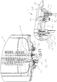
- FIG. 1 shows a hot water tank 1 according to a first example for understanding the invention.
- the hot water tank 1 has an inner container 10 and an outer container 20. Provided between the inner container 10 and the outer container 20 in a cavity H. If the hot water tank 1 is insulated, then a flowable or free-flowing, insulating medium 30 is filled through a filling opening 23 of the outer container 20. Air is withdrawn from the cavity H via a suction nozzle 22 and the cavity H evacuated. In order to avoid contamination of an evacuation pump, not shown, a fine filter 220 is disposed in front of the suction nozzle 22. In an opening region 1000, the outer container 20 has an outer ring 21 and the inner container 10 has an inner ring 11.
- a gap S is provided between the inner ring 11 and the outer ring 21, which reduces a heat transfer to the outside. Furthermore, an opening 12 for receiving a Schuflansches not shown is provided on the inner container 10. Optionally, in the region of the filling opening 23 of the outer container 20, a connection 24 is provided for a measured value recording.
- FIG. 2a is a detailed view of the hot water tank 1 from FIG. 1 shown.
- the hot water storage tank 1 has an inner tank 10 and an outer tank 20. Between the inner container 10 and the outer container 20, a cavity H for receiving an insulating medium 30 for insulation of the hot water tank 1 is provided.
- the inner container 10 has an opening 12 for receiving a Schuflansches not shown.
- the inner container 10 has an inner ring 11 and the outer container 20 has an outer ring 21.
- the inner ring 11 and the outer ring 12 are for Connection of inner container 10 and outer container 20 connected to each other. Between the inner ring 11 and the outer ring 21, a gap S is provided.
- FIG. 2b shows a more detailed view of the hot water tank 1 from FIG. 1 , Shown is in particular the container separation between the inner ring 11 of the inner container 10 and the outer ring 21 of the outer container 20 in the region of the opening portion 100.
- the container separation serves to reduce the heat transfer to the outside. This effect is achieved in that the heat that occurs in the interior of the container, initially via the inner ring 11 and then via the outer ring 21 is derived.
- the distance over which the heat is dissipated is lengthened, in that the heat is first conducted in the direction W1 via the inner ring 11, then in the direction W2 to the outer ring 21 and then in the direction W3 via the outer ring 21.
- a cavity between the inner container 10 and the outer container 20 is provided for receiving an insulating medium 30.
- FIG. 3 shows a schematic sectional view of a hot water tank according to a second example for understanding the invention.
- the hot water tank has a storage tank 200 and an insulation or an insulation unit 300.
- This insulation or isolation unit 300 may be configured as a vacuum insulation unit.
- the storage container 200 has an opening 213 at its lower end 212. In this opening 213 z. B. the heating flange 40 are introduced.
- the storage container 200 may be configured with an inner container and an outer container as described in the first example.
- FIG. 4 shows an enlarged partial sectional view of the hot water tank of FIG. 3
- the storage container 200 has at its lower end an opening 213 into which a heating flange can be inserted.
- a cylindrical ring 212 is also provided, for example, made of stainless steel.
- the insulation or the insulation unit 300 of the hot water tank can also be made or configured at its bottom 301 of stainless steel.
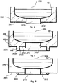
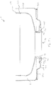
- FIG. 5 shows a partial sectional view of a hot water tank according to a first embodiment.
- the hot water tank has a storage tank 200 with a lower end, which may be configured as a cylindrical ring 212, for example made of stainless steel.
- the ring 212 surrounds an opening 213 into which a heating flange can be inserted.
- the hot water tank according to the first embodiment substantially corresponds to the hot water tank according to the first or second example for understanding the invention and additionally has a cold sink 302 at its bottom.
- the cold sink 302 may be provided on the bottom 301 of the insulating unit 300 and may be formed, for example, as a circumferential ring 302.
- the cold sink 302 has a first portion 302a, a second portion 302b, a third portion 302c, and a height 302h.
- the first portion 302a may be 5 mm to 500 mm
- the second portion 302b may be 5 mm to 500 mm
- the third portion 302c may be 5 mm to 500 mm.
- the height 302h of the ring 302 may be, for example, 5 mm to 200 mm.
- FIG. 6 shows a partial sectional view of a hot water tank according to a second embodiment.
- the storage container 200 has at its lower end a cylindrical ring 212 which surrounds an opening 213 into which a heating flange can be inserted.
- an insulator 300 is provided, which may be configured, for example, as a vacuum insulation.
- a cold sink 303 is configured, which may be formed as a ring.
- the ring may have a radius of between 5 mm to 100 mm in cross section.
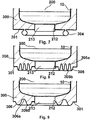
- FIGS. 7 to 9 show partial sectional views of a hot water tank according to a third to fifth embodiment.
- FIGS. 7 to 9 substantially correspond to the above first or second embodiment and illustrate alternative embodiments of a cold sink on the underside 301 of the insulating unit 300.
- FIG. 7 shows a cold sink 304, which surrounds the opening 213 in the form of a ring.
- the cold sink 304 is approximately circular in cross section and shows a compared to the cold sink 303 tapered connecting portion with the bottom 301 of Insulating unit 300. This embodiment allows a further extended distance to be covered, so that the heat flow inhibition is further increased.
- FIG. 8 shows a cold sink 305 in the form of alternatingly inwardly into the insulating unit 300 reaching into bellies 305a and outwardly over the bottom 301 protruding troughs 305b.
- FIG. 9 shows a cold sink 306, which substantially corresponds to the waveform of FIG FIG. 8 showndeesenke 305 corresponds.
- the troughs 306b and the antinodes 306a are farther apart from each other in the radial direction from the opening 213 as compared with the cold sink 305.
- the exact locations and distances of the troughs 305b, 306b or the antinodes 305a, 306a may be adjusted as needed.
- the cold sinks 305, 306 may not extend beyond the bottom 301 into the insulation unit 300 and may be provided below the bottom 301 only.
- the cold sink can also be designed differently, for example, have a different shape, as long as it is adapted to inhibit the heat flow from the interior of the container to the outside and to improve the insulating properties of the insulating unit 300.
- Mixed forms of the embodiments of the cold sinks are inventively conceivable.
- FIGS. 10 to 14 show schematic partial sectional views of an outer sheath of a hot water tank according to a sixth to tenth embodiment.
- the show FIGS. 10 to 14 Various types of joining, such as a jacket portion 320 of the insulating unit 300 is connected to a cover portion 330 of the insulating unit.
- the not shown part of the hot water tank can correspond to the hot water tank of the first or second embodiment.
- the shell portion 320 protrudes upward beyond the lid portion 330 addition.
- a fillet weld 340a in the form of a horizontal T-joint of the cover part 330 is provided for connection.
- the cover member 330 extends horizontally beyond the shell portion 320 to the outside.
- a fillet weld 340 b is provided for connecting the cover part 330 to the cover part 320, the cover part 320 being in T-joint of the cover part 320.
- the cover part 330 and the jacket part 320 are welded on impact, wherein, for example, a fillet weld 340c designed as a corner seam or corner joint connects the two parts.
- the lid member 330 adjacent to the skirt 320 has an upwardly bent portion 330d.
- the upwardly bent portion 330d welded to the shell portion 320 by means of a butt weld 340d.
- the lid portion 330 is bent down in the vicinity of the shell portion 320 and forms an overlap region 330e.
- the overlapping area 330e is welded to the shell portion 320 by means of a weld 340e.
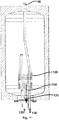
- Fig. 15 shows a schematic sectional view of a hot water tank 1 with a Walkerflanschvortechnisch 100 according to an embodiment of the invention.
- the hot water tank 1 has a storage shell 2, which surrounds a storage tank 3.
- the storage shell 2 in turn has an outer wall 20 and an inner wall 10, which are separated from each other by a vacuum insulation 16. Via a filler neck 18, the space between outer wall 20 and inner wall 10 can be filled with insulating medium, for example, and be evacuated.
- the storage enclosure 2 has an opening 13, via which a Schuflanschvortechnisch 100 is inserted into the container interior.
- the filler neck can be mounted in another embodiment on the storage jacket, in particular in the region of a wall bracket.
- the storage tank 3 preferably different water layers are formed, in particular during the removal of hot water.
- the lower region of the storage container 3 are colder water layers 22, while 3 warm water layers 24 are formed in the upper region of the storage container. This is done because in the hot water tank 1 fresh water is introduced from below into the storage tank 3, there heated by the Schuflanschvoriques and heated in the upper region is discharged from the storage tank 3. The inflow of the fresh water is thus designed to ensure the lowest possible mixing of the water in the storage tank 3.
- the storage container 3 is under pressure and is preferably full or almost completely filled during operation.
- a water level 26 is advantageously above a hot water outlet 134th
- Fig. 16a and 16b show enlarged detail views of in Fig. 15 shown schematic sectional view of the hot water tank 1.
- Fig. 16a the upper portion of the hot water tank 1
- Fig. 16b the lower portion of the hot water tank 1 with a majority of Schuflanschvorraum 100th
- the individual components of Bankflanschvorraum 100 can be seen.
- the Bankflanschvortechnik 100 includes three heating elements 110, each with two terminals 112.
- the terminals 112 are typical connections for heating elements in hot water tanks and protrude down from the hot water tank 1 via a flange 105 addition.
- the heating elements 110 are preferably heating elements each with a heating power of 2 kW, although other heating powers and / or a different number of heating elements 110 can also be envisaged.
- a hot water return 130 projects from below through the flange 105 upwards.
- a hot water pipe 132 forms an upper part of the water return 130 and is led upwards through the storage container interior and ends at a hot water outlet 134 Fig. 16
- a temperature sensor 140 is shown, which also protrudes almost or completely through the entire storage tank volume, preferably designed as an integral sensor and can detect a temperature of the water over the entire storage area.
- Fig. 16b a corrosion protection unit in the form of an external current anode 150.
- the external current anode 150 is inserted into the interior of the storage container 3 via an opening in the flange element 105. Opposite the flange element 105, the foreign current anode 150 is insulated by means of an insulation 155.
- a corrosion protection voltage between flange member 105 and the foreign current anode 150, which is connectable via a terminal 152, can be applied.
- the foreign current anode 150 may also be replaced by another corrosion protection unit, such as a magnesium anode.
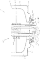
- Fig. 17 shows a further enlarged schematic sectional view of the area of the hot water tank 1, as shown in Fig. 16b is shown. In particular shows Fig. 17 the attachment of Bankflanschvortechnisch 100 to the hot water tank. 1
- Fig. 17 shows in detail a threaded ring 40 which is disposed between a bottom 301 of the outer wall 20 of the storage shell 2 and a side wall 19 of the opening 13.
- the threaded ring 40 is used to attach the Schuflanschvorraum 100 to the hot water tank 1.
- the side wall 19 of the opening 13 protrudes downward beyond the bottom 301a of the storage enclosure.
- the threaded ring 30 can thus be attached to both the bottom 301 a and the side wall 19 of the opening 13 without blocking a portion of the opening 13.
- the threaded ring 40 surrounds the opening 13 and is welded to the bottom 301 a and / or the side wall 19 of the opening 13.
- the Schuflanschvorraum 100 or in particular the flange 105 is attached to the hot water tank 1, the fastening means 103, in particular screws, between the flange 105 and the threaded ring 40 are provided.
- the flange element 105 can be firmly connected to the threaded ring 40 without the fastening means 103 penetrating into the storage shell and damaging the vacuum insulation between the outer wall 20 and the inner wall 10.
- a sealing element 109 for example made of plastic, is provided.
- the sealing element 109 seals the container interior with respect to the outside space.
- the flange 105 may have a ground terminal 107 through which the hot water tank 1 is connected to ground.
- the hot water tank 1 no vacuum insulation. Therefore, it may be advantageous in some embodiments to provide above the flange member 105 and the entire Schuflanschvoriques 100 and the threaded ring 40, a further insulating body, for example made of styrofoam, plastic or other heat-insulating materials, the heat transfer via the opening 13 from the container interior insulates outside.
- a further insulating body for example made of styrofoam, plastic or other heat-insulating materials
- Fig. 18 shows a schematic sectional view of a hot water tank 1 with a Schuflanschvoroplasty 100 according to an embodiment of the invention.
- hot water tank is additionally shown the cold water inlet 120, advantageously with a mixing limiter in the form of an impact protection 125.
- the other elements correspond to the elements shown in the previous drawings, and a description thereof will not be repeated.
- cold water inlet or cold water inlet 120 cold water flows into the lower tank area.
- an impact protection 125th provided, which essentially means that the cold water inlet is closed with a horizontal end, whereby a flow of the inflowing water is braked vertically.
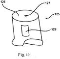
- Fig. 19 shows schematically and exemplarily an inventive impact protection according to an embodiment.
- the impact protection 125 connects to the cold water inlet 120 and is connected thereto and is closed at its upper end with a closure 126. Only a small hole 127 allows a flow of a small volume of water directly from the cold water inlet 120 upwards. The much larger portion of the inflowing water is diverted to lateral openings 129 and thus leaves the cold water inlet 120 and the impact protection 125 horizontally. As a result, a mixing of the water in the storage tank 30 is kept as small as possible.
- a baffle plate may be provided, which also serves to limit a vertical flow of the inflowing cold water.
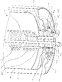
- Figs. 20a and 20b Each shows horizontal sectional views of an embodiment of Bankflanschvor512 100th Fig. 20a shows a sectional view of the Bankflanschvortechnik 100 from above, where going Fig. 20b a sectional view of the Schuflanschvortechnik 100 from below shows.
- the reference numerals of the individual elements correspond to those with reference to Fig. 1 to Fig. 19 used reference numerals, which are not repeated here. It should be understood that the arrangement shown is, of course, only one example of the possible arrangements of the elements in the heating flange apparatus 100. Other arrangements of the connections are conceivable as long as the geometry of the elements allows mounting of the Edelflanschvoroplasty 100 through the opening 13 of the hot water tank 1.
- a sensor tube is provided, in which the temperature sensor 140 and another, not shown, safety temperature limiters are arranged.
- the sensor tube may be arranged instead of the temperature sensor 140 shown in the drawings.
- a separate terminal or position may be provided in the safety temperature limiter flange member.
- Fig. 21 shows a further embodiment of the Schuflansches 100 schematically
- Fig. 22 schematically shows a cross section of another embodiment of a hot water tank 1.
- the inner container 10 is divided into two and connected to a weld seam 351. Both parts of the inner container 10 are made of enamelled steel. Through the enamel, the inner container is corrosion resistant and reduces the heat conduction.
- the outer container 20, steel in this example, is welded to the stainless steel bottom 301 at a transition region 352. Between the inner container 10 and the bottom 301, a side wall 19 made of steel at two welds 353 and 354 is welded.
- the formed in this example as a web side wall 19 is designed as galvanized and / or painted steel.
- the side wall 19 is designed as a web 190 with a subsequent spread portion 192.
- the opening 12 widened which is indicated by the reference numeral 194, in order to provide a sufficiently large contact surface for the seal between the container and the heating flange device 100 to be introduced into the opening 12.
- the bottom 301 has a cold sink 307, which in this example has, in particular, an indentation 307a extending into the cavity H, with a further region 307b extending further outward therebehind.
- a cold sink 307 which in this example has, in particular, an indentation 307a extending into the cavity H, with a further region 307b extending further outward therebehind.
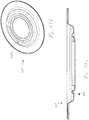
- Figs. 23a and 23b show two views of the bottom 301. In this case, in particular the achieved by the cold sink 307, extended heat transfer path is clear.
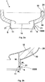
- Figs. 24a and 24b 2 schematically show two views of the side wall 19 designed as a web 190 and a distributed element 192.
- the widening region 194 of the opening 12 becomes clear.
- Fig. 25 schematically shows a view of the in Fig. 22 shown hot water tank 1, in which a Bankflanschvorraum 100 is inserted into the opening 12.
- the embodiment of Bankflanschvorraum 100 substantially corresponds to that of the preceding embodiments, wherein the flange member 105 is designed as a flange plate made of stainless steel, which adapts particularly well to the shape of the cold sink 307.
- the flange member 105 is designed as a flange plate made of stainless steel, which adapts particularly well to the shape of the cold sink 307.
- Screw-equipped fasteners 309 circumferentially and arranged around the side wall 9 around.
- the fastening means 309 are welded to the bottom plate 301, in particular spot-welded.
- the flange plate 105 is connected to the bottom 301 by fastening means 103 configured as nuts.
- a spacer 104 preferably made of hard plastic, is provided between the screw 309 and the nut 103. As a result, the flange member 105 is electrically isolated from the container.
- the flange plate 105 is insulated from the container by the sealing member 109 between the side wall 19 and flange plate 105.
- the embodiment of the sealing element 109 is in Figs. 26a and 26b shown in more detail in two views.
- the sealing element 109 has two grooves 109a and 109b, which produce a particularly secure seal similar to the principle of a windscreen wiper when clamping. The secure seal is also ensured by the wide support, which is ensured by the widened portion 194.
- Figs. 27a and 27b show further schematic views of the hot water tank 1 in which in particular the isolation of the flange member 105 relative to the container by the sealing element 109 and the spacer 104 is visible.
- Fig. 27b also shows in detail the connection of the foreign current anode 150. Between foreign current anode 150 and flange 105 is provided a seal 154 for waterproofing and an insulation 156 for electrical insulation. The external current anode 150 is connected via a connection 152 and screwed to a nut 158. Thus, the actual anode, which protrudes into the container interior, be replaced with removed Schuflanschvorraum 100.
- Fig. 27a also shows an embodiment of the cold water inlet 120, which differs from the other embodiments.
- the fresh water inlet 120 is bent in the direction of the flange element 105 such that the cold water in the direction of the flange 105 and the side wall 19 is guided.
- the flange member 105 and the side wall 19 act in this embodiment accordingly as a baffle plate.
- a plane of the flange member 105 and the water outlet of the cold water inlet 120 thus include an angle which is less than 90 degrees.
- the Fig. 28 shows this embodiment in further views. It serves to illustrate at least one of the aspects discussed above.
Landscapes
- Engineering & Computer Science (AREA)
- Physics & Mathematics (AREA)
- Thermal Sciences (AREA)
- Chemical & Material Sciences (AREA)
- Combustion & Propulsion (AREA)
- Mechanical Engineering (AREA)
- General Engineering & Computer Science (AREA)
- Heat-Pump Type And Storage Water Heaters (AREA)
- Details Of Fluid Heaters (AREA)
Priority Applications (1)
| Application Number | Priority Date | Filing Date | Title |
|---|---|---|---|
| PL17198742T PL3315872T3 (pl) | 2016-10-27 | 2017-10-27 | Zasobnik ciepłej wody i kołnierz grzewczy dla zasobnika ciepłej wody |
Applications Claiming Priority (2)
| Application Number | Priority Date | Filing Date | Title |
|---|---|---|---|
| DE102016012922.0A DE102016012922A1 (de) | 2016-10-27 | 2016-10-27 | Warmwasserspeicher und Verfahren zur Dämmung eines Warmwasserspeichers |
| DE102016012921.2A DE102016012921A1 (de) | 2016-10-27 | 2016-10-27 | Heizflanschvorrichtung für einen Warmwasserspeicher und Warmwasserspeicher |
Publications (3)
| Publication Number | Publication Date |
|---|---|
| EP3315872A2 true EP3315872A2 (fr) | 2018-05-02 |
| EP3315872A3 EP3315872A3 (fr) | 2018-08-22 |
| EP3315872B1 EP3315872B1 (fr) | 2021-03-10 |
Family
ID=60191167
Family Applications (1)
| Application Number | Title | Priority Date | Filing Date |
|---|---|---|---|
| EP17198742.3A Active EP3315872B1 (fr) | 2016-10-27 | 2017-10-27 | Ballon d'eau chaude et flasque chauffant pour un ballon d'eau chaude |
Country Status (2)
| Country | Link |
|---|---|
| EP (1) | EP3315872B1 (fr) |
| PL (1) | PL3315872T3 (fr) |
Cited By (4)
| Publication number | Priority date | Publication date | Assignee | Title |
|---|---|---|---|---|
| EP3705804A1 (fr) * | 2019-03-07 | 2020-09-09 | Stiebel Eltron GmbH & Co. KG | Appareil domestique et raccord à bride pour un tel appareil domestique |
| EP3705805A1 (fr) * | 2019-03-08 | 2020-09-09 | Stiebel Eltron GmbH & Co. KG | Petit accumulateur d'eau chaude |
| EP4060247A1 (fr) * | 2021-03-10 | 2022-09-21 | Viessmann Climate Solutions SE | Appareil de technique de chauffage |
| EP4386277A1 (fr) * | 2022-12-14 | 2024-06-19 | Stiebel Eltron GmbH & Co. KG | Accumulateur à vide et procédé de fabrication d'un accumulateur à vide |
Family Cites Families (9)
| Publication number | Priority date | Publication date | Assignee | Title |
|---|---|---|---|---|
| CH121759A (de) * | 1926-07-06 | 1927-08-16 | Kummler & Matter Ag | Anordnung an elektrischen Heisswasserspeichern zur Verhinderung von Wärmeverlusten. |
| US3056738A (en) * | 1959-02-02 | 1962-10-02 | Harry C Fischer | Impressed current cathodic protection system |
| US3715566A (en) * | 1972-01-24 | 1973-02-06 | Smith Corp A | Corrosion guard system for electric water heater |
| DE2916660A1 (de) * | 1979-04-25 | 1980-11-13 | Stiebel Eltron Gmbh & Co Kg | Elektrischer heisswasserbereiter |
| DE3805559A1 (de) * | 1988-02-23 | 1989-08-31 | Forbach Gmbh | Elektrischer heisswasserbereiter |
| DE102006025875A1 (de) * | 2006-06-02 | 2007-12-06 | Greiner Purtec Gmbh | Wärmedämmende Umkleidung für Körper, insbesondere für Warmwasserspeicher |
| JP5283495B2 (ja) * | 2008-12-11 | 2013-09-04 | 株式会社ジャムコ | 航空機搭載用給湯装置 |
| EP2636968B1 (fr) * | 2012-03-07 | 2015-04-29 | Roth Werke GmbH | Récipient de stockage et procédé de montage d'un récipient de stockage |
| DE102013016705A1 (de) * | 2013-10-09 | 2015-04-09 | Stiebel Eltron Gmbh & Co. Kg | Verfahren zur Dämmung eines Warmwasserspeichers und Warmwasserspeicher |
-
2017
- 2017-10-27 PL PL17198742T patent/PL3315872T3/pl unknown
- 2017-10-27 EP EP17198742.3A patent/EP3315872B1/fr active Active
Cited By (5)
| Publication number | Priority date | Publication date | Assignee | Title |
|---|---|---|---|---|
| EP3705804A1 (fr) * | 2019-03-07 | 2020-09-09 | Stiebel Eltron GmbH & Co. KG | Appareil domestique et raccord à bride pour un tel appareil domestique |
| EP3705805A1 (fr) * | 2019-03-08 | 2020-09-09 | Stiebel Eltron GmbH & Co. KG | Petit accumulateur d'eau chaude |
| EP4060247A1 (fr) * | 2021-03-10 | 2022-09-21 | Viessmann Climate Solutions SE | Appareil de technique de chauffage |
| EP4060247B1 (fr) | 2021-03-10 | 2024-09-11 | Viessmann Climate Solutions SE | Appareil de technique de chauffage |
| EP4386277A1 (fr) * | 2022-12-14 | 2024-06-19 | Stiebel Eltron GmbH & Co. KG | Accumulateur à vide et procédé de fabrication d'un accumulateur à vide |
Also Published As
| Publication number | Publication date |
|---|---|
| EP3315872B1 (fr) | 2021-03-10 |
| EP3315872A3 (fr) | 2018-08-22 |
| PL3315872T3 (pl) | 2021-09-20 |
Similar Documents
| Publication | Publication Date | Title |
|---|---|---|
| EP3315872B1 (fr) | Ballon d'eau chaude et flasque chauffant pour un ballon d'eau chaude | |
| DE60011602T2 (de) | Vakuumisoliertes heisswassergerät zum anschliessen an eine wasserleitung | |
| DE3941331C1 (fr) | ||
| DE102016012921A1 (de) | Heizflanschvorrichtung für einen Warmwasserspeicher und Warmwasserspeicher | |
| EP1902944B1 (fr) | Propulsion navale | |
| DE2517126A1 (de) | Vorrichtung zur ausnutzung des waermeinhalts von abwaessern | |
| EP2281154A2 (fr) | Pied de sonde a structure modulaire et ses composants | |
| EP3027975A1 (fr) | Chauffe-eau | |
| DE102016106180A1 (de) | Kühlvorrichtung für die Kühlung wenigstens einer elektrischen Komponente eines Fahrzeugs | |
| DE2919964A1 (de) | Keramischer infrarotstrahler und daraus gebildete strahlungsanlage | |
| DE19722635C2 (de) | Innenbehälter für einen Heißwasserspeicher | |
| DE102016012922A1 (de) | Warmwasserspeicher und Verfahren zur Dämmung eines Warmwasserspeichers | |
| DE19636143C1 (de) | Innenbehälter eines Heißwasserbereiters | |
| DE202004021811U1 (de) | Schichtenspeicher mit einem Gehäuse und einer Isolierung | |
| EP2336668A2 (fr) | Dispositif de chauffage d'eau doté d'un support à isolation thermique | |
| DE19741093B4 (de) | Heizflansch für einen wandinstallierbaren Warmwasserbereiter, insbesondere Kochendwassergerät | |
| DE102006010872B4 (de) | Beschichtungsanlage mit kühlbarer Blende | |
| DE9100476U1 (de) | Reinigungsmaschinen-Beheizung | |
| DE102004020822A1 (de) | Warmwasserbereiter, insbesondere Warmwasserspeicher, Wasserbehälter hierzu und Verfahren zu deren Herstellung | |
| DE202009015272U1 (de) | Elektrischer Wassererhitzungsbehälter mit austauschbarer Wassererhitzungsplatte | |
| DE102019001629A1 (de) | Warmwasser-Kleinspeicher | |
| DE2450571C3 (de) | Transformatorstation | |
| DE19608108C2 (de) | Kühlvorrichtung | |
| DE202020001996U1 (de) | Tauchkühler, insbesondere zur Kühlung von trinkbaren Flüssigkeiten | |
| DE19829507A1 (de) | Innenbehälter für einen Heißwasserspeicher mit einem Flächenheizkörper |
Legal Events
| Date | Code | Title | Description |
|---|---|---|---|
| PUAI | Public reference made under article 153(3) epc to a published international application that has entered the european phase |
Free format text: ORIGINAL CODE: 0009012 |
|
| STAA | Information on the status of an ep patent application or granted ep patent |
Free format text: STATUS: THE APPLICATION HAS BEEN PUBLISHED |
|
| AK | Designated contracting states |
Kind code of ref document: A2 Designated state(s): AL AT BE BG CH CY CZ DE DK EE ES FI FR GB GR HR HU IE IS IT LI LT LU LV MC MK MT NL NO PL PT RO RS SE SI SK SM TR |
|
| AX | Request for extension of the european patent |
Extension state: BA ME |
|
| PUAL | Search report despatched |
Free format text: ORIGINAL CODE: 0009013 |
|
| AK | Designated contracting states |
Kind code of ref document: A3 Designated state(s): AL AT BE BG CH CY CZ DE DK EE ES FI FR GB GR HR HU IE IS IT LI LT LU LV MC MK MT NL NO PL PT RO RS SE SI SK SM TR |
|
| AX | Request for extension of the european patent |
Extension state: BA ME |
|
| RIC1 | Information provided on ipc code assigned before grant |
Ipc: F28D 20/00 20060101ALI20180713BHEP Ipc: F24H 9/00 20060101ALI20180713BHEP Ipc: F24H 1/20 20060101ALI20180713BHEP Ipc: F24H 1/18 20060101AFI20180713BHEP |
|
| STAA | Information on the status of an ep patent application or granted ep patent |
Free format text: STATUS: REQUEST FOR EXAMINATION WAS MADE |
|
| 17P | Request for examination filed |
Effective date: 20190222 |
|
| RBV | Designated contracting states (corrected) |
Designated state(s): AL AT BE BG CH CY CZ DE DK EE ES FI FR GB GR HR HU IE IS IT LI LT LU LV MC MK MT NL NO PL PT RO RS SE SI SK SM TR |
|
| STAA | Information on the status of an ep patent application or granted ep patent |
Free format text: STATUS: EXAMINATION IS IN PROGRESS |
|
| 17Q | First examination report despatched |
Effective date: 20191031 |
|
| GRAP | Despatch of communication of intention to grant a patent |
Free format text: ORIGINAL CODE: EPIDOSNIGR1 |
|
| STAA | Information on the status of an ep patent application or granted ep patent |
Free format text: STATUS: GRANT OF PATENT IS INTENDED |
|
| INTG | Intention to grant announced |
Effective date: 20200506 |
|
| GRAJ | Information related to disapproval of communication of intention to grant by the applicant or resumption of examination proceedings by the epo deleted |
Free format text: ORIGINAL CODE: EPIDOSDIGR1 |
|
| STAA | Information on the status of an ep patent application or granted ep patent |
Free format text: STATUS: EXAMINATION IS IN PROGRESS |
|
| GRAP | Despatch of communication of intention to grant a patent |
Free format text: ORIGINAL CODE: EPIDOSNIGR1 |
|
| STAA | Information on the status of an ep patent application or granted ep patent |
Free format text: STATUS: GRANT OF PATENT IS INTENDED |
|
| INTC | Intention to grant announced (deleted) | ||
| INTG | Intention to grant announced |
Effective date: 20201013 |
|
| GRAS | Grant fee paid |
Free format text: ORIGINAL CODE: EPIDOSNIGR3 |
|
| GRAA | (expected) grant |
Free format text: ORIGINAL CODE: 0009210 |
|
| STAA | Information on the status of an ep patent application or granted ep patent |
Free format text: STATUS: THE PATENT HAS BEEN GRANTED |
|
| AK | Designated contracting states |
Kind code of ref document: B1 Designated state(s): AL AT BE BG CH CY CZ DE DK EE ES FI FR GB GR HR HU IE IS IT LI LT LU LV MC MK MT NL NO PL PT RO RS SE SI SK SM TR |
|
| REG | Reference to a national code |
Ref country code: GB Ref legal event code: FG4D Free format text: NOT ENGLISH |
|
| REG | Reference to a national code |
Ref country code: CH Ref legal event code: EP Ref country code: AT Ref legal event code: REF Ref document number: 1370239 Country of ref document: AT Kind code of ref document: T Effective date: 20210315 |
|
| REG | Reference to a national code |
Ref country code: IE Ref legal event code: FG4D Free format text: LANGUAGE OF EP DOCUMENT: GERMAN |
|
| REG | Reference to a national code |
Ref country code: DE Ref legal event code: R096 Ref document number: 502017009641 Country of ref document: DE |
|
| REG | Reference to a national code |
Ref country code: NL Ref legal event code: FP |
|
| REG | Reference to a national code |
Ref country code: LT Ref legal event code: MG9D |
|
| PG25 | Lapsed in a contracting state [announced via postgrant information from national office to epo] |
Ref country code: LT Free format text: LAPSE BECAUSE OF FAILURE TO SUBMIT A TRANSLATION OF THE DESCRIPTION OR TO PAY THE FEE WITHIN THE PRESCRIBED TIME-LIMIT Effective date: 20210310 Ref country code: BG Free format text: LAPSE BECAUSE OF FAILURE TO SUBMIT A TRANSLATION OF THE DESCRIPTION OR TO PAY THE FEE WITHIN THE PRESCRIBED TIME-LIMIT Effective date: 20210610 Ref country code: HR Free format text: LAPSE BECAUSE OF FAILURE TO SUBMIT A TRANSLATION OF THE DESCRIPTION OR TO PAY THE FEE WITHIN THE PRESCRIBED TIME-LIMIT Effective date: 20210310 Ref country code: GR Free format text: LAPSE BECAUSE OF FAILURE TO SUBMIT A TRANSLATION OF THE DESCRIPTION OR TO PAY THE FEE WITHIN THE PRESCRIBED TIME-LIMIT Effective date: 20210611 Ref country code: FI Free format text: LAPSE BECAUSE OF FAILURE TO SUBMIT A TRANSLATION OF THE DESCRIPTION OR TO PAY THE FEE WITHIN THE PRESCRIBED TIME-LIMIT Effective date: 20210310 Ref country code: NO Free format text: LAPSE BECAUSE OF FAILURE TO SUBMIT A TRANSLATION OF THE DESCRIPTION OR TO PAY THE FEE WITHIN THE PRESCRIBED TIME-LIMIT Effective date: 20210610 |
|
| PG25 | Lapsed in a contracting state [announced via postgrant information from national office to epo] |
Ref country code: SE Free format text: LAPSE BECAUSE OF FAILURE TO SUBMIT A TRANSLATION OF THE DESCRIPTION OR TO PAY THE FEE WITHIN THE PRESCRIBED TIME-LIMIT Effective date: 20210310 Ref country code: RS Free format text: LAPSE BECAUSE OF FAILURE TO SUBMIT A TRANSLATION OF THE DESCRIPTION OR TO PAY THE FEE WITHIN THE PRESCRIBED TIME-LIMIT Effective date: 20210310 Ref country code: LV Free format text: LAPSE BECAUSE OF FAILURE TO SUBMIT A TRANSLATION OF THE DESCRIPTION OR TO PAY THE FEE WITHIN THE PRESCRIBED TIME-LIMIT Effective date: 20210310 |
|
| PG25 | Lapsed in a contracting state [announced via postgrant information from national office to epo] |
Ref country code: SM Free format text: LAPSE BECAUSE OF FAILURE TO SUBMIT A TRANSLATION OF THE DESCRIPTION OR TO PAY THE FEE WITHIN THE PRESCRIBED TIME-LIMIT Effective date: 20210310 Ref country code: EE Free format text: LAPSE BECAUSE OF FAILURE TO SUBMIT A TRANSLATION OF THE DESCRIPTION OR TO PAY THE FEE WITHIN THE PRESCRIBED TIME-LIMIT Effective date: 20210310 |
|
| PG25 | Lapsed in a contracting state [announced via postgrant information from national office to epo] |
Ref country code: PT Free format text: LAPSE BECAUSE OF FAILURE TO SUBMIT A TRANSLATION OF THE DESCRIPTION OR TO PAY THE FEE WITHIN THE PRESCRIBED TIME-LIMIT Effective date: 20210712 Ref country code: RO Free format text: LAPSE BECAUSE OF FAILURE TO SUBMIT A TRANSLATION OF THE DESCRIPTION OR TO PAY THE FEE WITHIN THE PRESCRIBED TIME-LIMIT Effective date: 20210310 Ref country code: SK Free format text: LAPSE BECAUSE OF FAILURE TO SUBMIT A TRANSLATION OF THE DESCRIPTION OR TO PAY THE FEE WITHIN THE PRESCRIBED TIME-LIMIT Effective date: 20210310 Ref country code: IS Free format text: LAPSE BECAUSE OF FAILURE TO SUBMIT A TRANSLATION OF THE DESCRIPTION OR TO PAY THE FEE WITHIN THE PRESCRIBED TIME-LIMIT Effective date: 20210710 |
|
| REG | Reference to a national code |
Ref country code: DE Ref legal event code: R097 Ref document number: 502017009641 Country of ref document: DE |
|
| PLBE | No opposition filed within time limit |
Free format text: ORIGINAL CODE: 0009261 |
|
| STAA | Information on the status of an ep patent application or granted ep patent |
Free format text: STATUS: NO OPPOSITION FILED WITHIN TIME LIMIT |
|
| PG25 | Lapsed in a contracting state [announced via postgrant information from national office to epo] |
Ref country code: DK Free format text: LAPSE BECAUSE OF FAILURE TO SUBMIT A TRANSLATION OF THE DESCRIPTION OR TO PAY THE FEE WITHIN THE PRESCRIBED TIME-LIMIT Effective date: 20210310 Ref country code: AL Free format text: LAPSE BECAUSE OF FAILURE TO SUBMIT A TRANSLATION OF THE DESCRIPTION OR TO PAY THE FEE WITHIN THE PRESCRIBED TIME-LIMIT Effective date: 20210310 Ref country code: ES Free format text: LAPSE BECAUSE OF FAILURE TO SUBMIT A TRANSLATION OF THE DESCRIPTION OR TO PAY THE FEE WITHIN THE PRESCRIBED TIME-LIMIT Effective date: 20210310 |
|
| 26N | No opposition filed |
Effective date: 20211213 |
|
| PG25 | Lapsed in a contracting state [announced via postgrant information from national office to epo] |
Ref country code: SI Free format text: LAPSE BECAUSE OF FAILURE TO SUBMIT A TRANSLATION OF THE DESCRIPTION OR TO PAY THE FEE WITHIN THE PRESCRIBED TIME-LIMIT Effective date: 20210310 |
|
| PG25 | Lapsed in a contracting state [announced via postgrant information from national office to epo] |
Ref country code: IT Free format text: LAPSE BECAUSE OF FAILURE TO SUBMIT A TRANSLATION OF THE DESCRIPTION OR TO PAY THE FEE WITHIN THE PRESCRIBED TIME-LIMIT Effective date: 20210310 |
|
| REG | Reference to a national code |
Ref country code: CH Ref legal event code: PL |
|
| PG25 | Lapsed in a contracting state [announced via postgrant information from national office to epo] |
Ref country code: IS Free format text: LAPSE BECAUSE OF FAILURE TO SUBMIT A TRANSLATION OF THE DESCRIPTION OR TO PAY THE FEE WITHIN THE PRESCRIBED TIME-LIMIT Effective date: 20210710 |
|
| GBPC | Gb: european patent ceased through non-payment of renewal fee |
Effective date: 20211027 |
|
| PG25 | Lapsed in a contracting state [announced via postgrant information from national office to epo] |
Ref country code: MC Free format text: LAPSE BECAUSE OF FAILURE TO SUBMIT A TRANSLATION OF THE DESCRIPTION OR TO PAY THE FEE WITHIN THE PRESCRIBED TIME-LIMIT Effective date: 20210310 |
|
| PG25 | Lapsed in a contracting state [announced via postgrant information from national office to epo] |
Ref country code: LU Free format text: LAPSE BECAUSE OF NON-PAYMENT OF DUE FEES Effective date: 20211027 Ref country code: GB Free format text: LAPSE BECAUSE OF NON-PAYMENT OF DUE FEES Effective date: 20211027 |
|
| PG25 | Lapsed in a contracting state [announced via postgrant information from national office to epo] |
Ref country code: LI Free format text: LAPSE BECAUSE OF NON-PAYMENT OF DUE FEES Effective date: 20211031 Ref country code: CH Free format text: LAPSE BECAUSE OF NON-PAYMENT OF DUE FEES Effective date: 20211031 |
|
| PG25 | Lapsed in a contracting state [announced via postgrant information from national office to epo] |
Ref country code: FR Free format text: LAPSE BECAUSE OF NON-PAYMENT OF DUE FEES Effective date: 20211031 |
|
| PG25 | Lapsed in a contracting state [announced via postgrant information from national office to epo] |
Ref country code: IE Free format text: LAPSE BECAUSE OF NON-PAYMENT OF DUE FEES Effective date: 20211027 |
|
| PG25 | Lapsed in a contracting state [announced via postgrant information from national office to epo] |
Ref country code: HU Free format text: LAPSE BECAUSE OF FAILURE TO SUBMIT A TRANSLATION OF THE DESCRIPTION OR TO PAY THE FEE WITHIN THE PRESCRIBED TIME-LIMIT; INVALID AB INITIO Effective date: 20171027 |
|
| P01 | Opt-out of the competence of the unified patent court (upc) registered |
Effective date: 20230524 |
|
| PG25 | Lapsed in a contracting state [announced via postgrant information from national office to epo] |
Ref country code: CY Free format text: LAPSE BECAUSE OF FAILURE TO SUBMIT A TRANSLATION OF THE DESCRIPTION OR TO PAY THE FEE WITHIN THE PRESCRIBED TIME-LIMIT Effective date: 20210310 |
|
| PG25 | Lapsed in a contracting state [announced via postgrant information from national office to epo] |
Ref country code: MK Free format text: LAPSE BECAUSE OF FAILURE TO SUBMIT A TRANSLATION OF THE DESCRIPTION OR TO PAY THE FEE WITHIN THE PRESCRIBED TIME-LIMIT Effective date: 20210310 |
|
| PG25 | Lapsed in a contracting state [announced via postgrant information from national office to epo] |
Ref country code: MT Free format text: LAPSE BECAUSE OF FAILURE TO SUBMIT A TRANSLATION OF THE DESCRIPTION OR TO PAY THE FEE WITHIN THE PRESCRIBED TIME-LIMIT Effective date: 20210310 |
|
| PGFP | Annual fee paid to national office [announced via postgrant information from national office to epo] |
Ref country code: NL Payment date: 20251021 Year of fee payment: 9 |
|
| PG25 | Lapsed in a contracting state [announced via postgrant information from national office to epo] |
Ref country code: TR Free format text: LAPSE BECAUSE OF FAILURE TO SUBMIT A TRANSLATION OF THE DESCRIPTION OR TO PAY THE FEE WITHIN THE PRESCRIBED TIME-LIMIT Effective date: 20210310 |
|
| PGFP | Annual fee paid to national office [announced via postgrant information from national office to epo] |
Ref country code: DE Payment date: 20251021 Year of fee payment: 9 |
|
| PGFP | Annual fee paid to national office [announced via postgrant information from national office to epo] |
Ref country code: AT Payment date: 20251022 Year of fee payment: 9 |
|
| PGFP | Annual fee paid to national office [announced via postgrant information from national office to epo] |
Ref country code: BE Payment date: 20251021 Year of fee payment: 9 |
|
| PGFP | Annual fee paid to national office [announced via postgrant information from national office to epo] |
Ref country code: CZ Payment date: 20251021 Year of fee payment: 9 |
|
| PGFP | Annual fee paid to national office [announced via postgrant information from national office to epo] |
Ref country code: PL Payment date: 20251016 Year of fee payment: 9 |