EP3316253B1 - Sprachsynthesevorrichtung, sprachsyntheseverfahren, knochenleitungshelm und hörgerät - Google Patents
Sprachsynthesevorrichtung, sprachsyntheseverfahren, knochenleitungshelm und hörgerät Download PDFInfo
- Publication number
- EP3316253B1 EP3316253B1 EP15864302.3A EP15864302A EP3316253B1 EP 3316253 B1 EP3316253 B1 EP 3316253B1 EP 15864302 A EP15864302 A EP 15864302A EP 3316253 B1 EP3316253 B1 EP 3316253B1
- Authority
- EP
- European Patent Office
- Prior art keywords
- detection
- node
- voice
- detection nodes
- trusted
- Prior art date
- Legal status (The legal status is an assumption and is not a legal conclusion. Google has not performed a legal analysis and makes no representation as to the accuracy of the status listed.)
- Active
Links
Images


Classifications
-
- H—ELECTRICITY
- H04—ELECTRIC COMMUNICATION TECHNIQUE
- H04R—LOUDSPEAKERS, MICROPHONES, GRAMOPHONE PICK-UPS OR LIKE ACOUSTIC ELECTROMECHANICAL TRANSDUCERS; ELECTRIC HEARING AIDS; PUBLIC ADDRESS SYSTEMS
- H04R3/00—Circuits for transducers
- H04R3/005—Circuits for transducers for combining the signals of two or more microphones
-
- G—PHYSICS
- G10—MUSICAL INSTRUMENTS; ACOUSTICS
- G10L—SPEECH ANALYSIS TECHNIQUES OR SPEECH SYNTHESIS; SPEECH RECOGNITION; SPEECH OR VOICE PROCESSING TECHNIQUES; SPEECH OR AUDIO CODING OR DECODING
- G10L13/00—Speech synthesis; Text to speech systems
- G10L13/02—Methods for producing synthetic speech; Speech synthesisers
-
- A—HUMAN NECESSITIES
- A42—HEADWEAR
- A42B—HATS; HEAD COVERINGS
- A42B3/00—Helmets; Helmet covers ; Other protective head coverings
- A42B3/04—Parts, details or accessories of helmets
- A42B3/30—Mounting radio sets or communication systems
-
- G—PHYSICS
- G10—MUSICAL INSTRUMENTS; ACOUSTICS
- G10L—SPEECH ANALYSIS TECHNIQUES OR SPEECH SYNTHESIS; SPEECH RECOGNITION; SPEECH OR VOICE PROCESSING TECHNIQUES; SPEECH OR AUDIO CODING OR DECODING
- G10L25/00—Speech or voice analysis techniques not restricted to a single one of groups G10L15/00 - G10L21/00
- G10L25/78—Detection of presence or absence of voice signals
- G10L25/84—Detection of presence or absence of voice signals for discriminating voice from noise
-
- H—ELECTRICITY
- H04—ELECTRIC COMMUNICATION TECHNIQUE
- H04R—LOUDSPEAKERS, MICROPHONES, GRAMOPHONE PICK-UPS OR LIKE ACOUSTIC ELECTROMECHANICAL TRANSDUCERS; ELECTRIC HEARING AIDS; PUBLIC ADDRESS SYSTEMS
- H04R1/00—Details of transducers, loudspeakers or microphones
- H04R1/02—Casings; Cabinets ; Supports therefor; Mountings therein
- H04R1/028—Casings; Cabinets ; Supports therefor; Mountings therein associated with devices performing functions other than acoustics, e.g. electric candles
-
- H—ELECTRICITY
- H04—ELECTRIC COMMUNICATION TECHNIQUE
- H04R—LOUDSPEAKERS, MICROPHONES, GRAMOPHONE PICK-UPS OR LIKE ACOUSTIC ELECTROMECHANICAL TRANSDUCERS; ELECTRIC HEARING AIDS; PUBLIC ADDRESS SYSTEMS
- H04R17/00—Piezoelectric transducers; Electrostrictive transducers
- H04R17/02—Microphones
-
- H—ELECTRICITY
- H04—ELECTRIC COMMUNICATION TECHNIQUE
- H04R—LOUDSPEAKERS, MICROPHONES, GRAMOPHONE PICK-UPS OR LIKE ACOUSTIC ELECTROMECHANICAL TRANSDUCERS; ELECTRIC HEARING AIDS; PUBLIC ADDRESS SYSTEMS
- H04R25/00—Electric hearing aids
-
- H—ELECTRICITY
- H04—ELECTRIC COMMUNICATION TECHNIQUE
- H04B—TRANSMISSION
- H04B1/00—Details of transmission systems, not covered by a single one of groups H04B3/00 - H04B13/00; Details of transmission systems not characterised by the medium used for transmission
- H04B1/38—Transceivers, i.e. devices in which transmitter and receiver form a structural unit and in which at least one part is used for functions of transmitting and receiving
- H04B1/3827—Portable transceivers
- H04B1/385—Transceivers carried on the body, e.g. in helmets
-
- H—ELECTRICITY
- H04—ELECTRIC COMMUNICATION TECHNIQUE
- H04R—LOUDSPEAKERS, MICROPHONES, GRAMOPHONE PICK-UPS OR LIKE ACOUSTIC ELECTROMECHANICAL TRANSDUCERS; ELECTRIC HEARING AIDS; PUBLIC ADDRESS SYSTEMS
- H04R1/00—Details of transducers, loudspeakers or microphones
- H04R1/10—Earpieces; Attachments therefor ; Earphones; Monophonic headphones
- H04R1/1058—Manufacture or assembly
- H04R1/1075—Mountings of transducers in earphones or headphones
-
- H—ELECTRICITY
- H04—ELECTRIC COMMUNICATION TECHNIQUE
- H04R—LOUDSPEAKERS, MICROPHONES, GRAMOPHONE PICK-UPS OR LIKE ACOUSTIC ELECTROMECHANICAL TRANSDUCERS; ELECTRIC HEARING AIDS; PUBLIC ADDRESS SYSTEMS
- H04R2201/00—Details of transducers, loudspeakers or microphones covered by H04R1/00 but not provided for in any of its subgroups
- H04R2201/02—Details casings, cabinets or mounting therein for transducers covered by H04R1/02 but not provided for in any of its subgroups
- H04R2201/023—Transducers incorporated in garment, rucksacks or the like
-
- H—ELECTRICITY
- H04—ELECTRIC COMMUNICATION TECHNIQUE
- H04R—LOUDSPEAKERS, MICROPHONES, GRAMOPHONE PICK-UPS OR LIKE ACOUSTIC ELECTROMECHANICAL TRANSDUCERS; ELECTRIC HEARING AIDS; PUBLIC ADDRESS SYSTEMS
- H04R2420/00—Details of connection covered by H04R, not provided for in its groups
- H04R2420/07—Applications of wireless loudspeakers or wireless microphones
-
- H—ELECTRICITY
- H04—ELECTRIC COMMUNICATION TECHNIQUE
- H04R—LOUDSPEAKERS, MICROPHONES, GRAMOPHONE PICK-UPS OR LIKE ACOUSTIC ELECTROMECHANICAL TRANSDUCERS; ELECTRIC HEARING AIDS; PUBLIC ADDRESS SYSTEMS
- H04R2460/00—Details of hearing devices, i.e. of ear- or headphones covered by H04R1/10 or H04R5/033 but not provided for in any of their subgroups, or of hearing aids covered by H04R25/00 but not provided for in any of its subgroups
- H04R2460/13—Hearing devices using bone conduction transducers
-
- H—ELECTRICITY
- H04—ELECTRIC COMMUNICATION TECHNIQUE
- H04R—LOUDSPEAKERS, MICROPHONES, GRAMOPHONE PICK-UPS OR LIKE ACOUSTIC ELECTROMECHANICAL TRANSDUCERS; ELECTRIC HEARING AIDS; PUBLIC ADDRESS SYSTEMS
- H04R25/00—Electric hearing aids
- H04R25/43—Electronic input selection or mixing based on input signal analysis, e.g. mixing or selection between microphone and telecoil or between microphones with different directivity characteristics
-
- H—ELECTRICITY
- H04—ELECTRIC COMMUNICATION TECHNIQUE
- H04R—LOUDSPEAKERS, MICROPHONES, GRAMOPHONE PICK-UPS OR LIKE ACOUSTIC ELECTROMECHANICAL TRANSDUCERS; ELECTRIC HEARING AIDS; PUBLIC ADDRESS SYSTEMS
- H04R25/00—Electric hearing aids
- H04R25/60—Mounting or interconnection of hearing aid parts, e.g. inside tips, housings or to ossicles
- H04R25/604—Mounting or interconnection of hearing aid parts, e.g. inside tips, housings or to ossicles of acoustic or vibrational transducers
- H04R25/606—Mounting or interconnection of hearing aid parts, e.g. inside tips, housings or to ossicles of acoustic or vibrational transducers acting directly on the eardrum, the ossicles or the skull, e.g. mastoid, tooth, maxillary or mandibular bone, or mechanically stimulating the cochlea, e.g. at the oval window
Definitions
- the present disclosure relates to the technical field of communication equipment, and more particularly, to a voice synthesis device, a voice synthesis method, a bone conduction helmet and a hearing aid.
- a bone conduction helmet has been used in the medical field.
- the application of the bone conduction helmet changes people's traditional cognition on voice, and its major advantage is that sound can be "heard" by the skull instead of the ears.
- a work principle of a bone conduction hearing aid is to use the bone conduction helmet to convert sound to an electrical signal, then to convert the amplified electrical signal to mechanical energy and transmit the mechanical energy to the skull, so as to vibrate the internal structure of the cochlea to transmit the sound.
- Existing bone conduction hearing aids are mainly divided into analog hearing aids and digital hearing aids.
- the analog hearing aid uniformly amplifies sound regardless of the shape of a patient's hearing loss curve.
- the digital hearing aid performs corresponding compensation and amplification on sound according to the shape of the patient's hearing loss curve.
- the existing digital hearing aid generally uses a voice signal detection sensor device in a bone conduction helmet, and detected voice signals are directly transmitted to the skull of a listener without verification. Such voice signals are high in bit error rate and low in accuracy.
- a prior art WO 2014/132167 A1 discloses a method and apparatus for generating a speech signal.
- an apparatus comprises microphone receivers which receive microphone signals from a plurality of microphones.
- a comparator determines a speech similarity indication indicative of a similarity between the microphone signal and non-reverberant speech for each microphone signal. The determination is in response to a comparison of a property derived from the microphone signal to a reference property for non-reverberant speech.
- the comparator determines the similarity indication by comparing to reference properties for speech samples of a set of non-reverberant speech samples.
- a generator generates a speech signal by combining the microphone signals in response to the similarity indications.
- the apparatus may be distributed over a plurality of devices each containing a microphone, and the approach may determine the most suited microphone for generating the speech signal.
- Embodiments of the present disclosure provide a voice synthesis device, a voice synthesis method, a bone conduction helmet and a hearing aid.
- a voice synthesis device comprising: a plurality of detection nodes configured to detect voice signals, and an aggregation node configured to receive the voice signals sent by the plurality of detection nodes, to determine whether each of the plurality of detection nodes is trusted, and to synthesize the voice signals sent by the detection nodes which are determined to be trusted to obtain synthesized voice signal.
- the voice synthesis device further comprises a central processing node configured to receive the synthesized voice signals transmitted by a plurality of aggregation nodes, and to synthesize the received synthesized voice signals.
- the aggregation node comprises: a first wireless transceiver configured to receive the voice signals sent by the plurality of detection nodes, and a first program controller configured to determine whether each of the plurality of detection nodes is trusted, and to synthesize the voice signals sent by the detection nodes which are determined to be trusted to obtain the synthesized voice signal.
- the first wireless transceiver is further configured to send the broadcast signal to the plurality of detection nodes, and receive the feedback signal from each of the plurality of detection nodes
- the first program controller is further configured to determine the trust degree for each of the plurality of detection nodes, and to determine whether the detection node is trusted based on its trust degree.
- the first program controller further comprises a voltage-stabilizing circuit.
- the first wireless transceiver is based on ZigBee wireless protocol.
- the aggregation node further comprises: a first voice sensing module configured to transmit the synthesized voice signal to the central processing node.
- the first voice sensing module is a piezoelectric vibration sensor.
- the detection node comprises: a second voice sensing module configured to detect the voice signal, and a second wireless transceiver configured to send the voice signal detected by the second voice sensing module to the aggregation node.
- the second wireless transceiver is further configured to receive the broadcast signal sent by the aggregation node, and send the feedback signal to the aggregation node.
- the second wireless transceiver is based on ZigBee wireless protocol.
- the second voice sensing module is a piezoelectric vibration sensor.
- a voice synthesis method comprising: receiving voice signals sent by a plurality of detection nodes, determining whether each of the plurality of detection nodes is trusted, and synthesizing the voice signals sent by the detection nodes which are determined to be trusted to obtain a synthesized voice signal.
- the predefined threshold is 0.3.
- a bone conduction helmet comprising: a helmet body and the foregoing voice synthesis device disposed on the helmet body.
- a plurality of detection nodes in the voice synthesis device are dispersedly disposed on the helmet body.
- a hearing aid comprising: the foregoing voice synthesis device.
- the plurality of detection nodes detects external voice signals and transmit the external voice signals to an aggregation node, and the aggregation node filters the detected voice signals and synthesizes the voice signals sent by detection nodes determined to be trusted.
- voice signals of untrusted detection nodes may be abandoned so that the voice signals actually used are trusted.
- the bit error rate of the voice signals can be reduced significantly, the accuracy of the voice signals can be improved, and the flexibility of the bone conduction helmet can be improved.
- the voice synthesis method of the embodiments of the present disclosure is strong in adaptability and high in reliability.
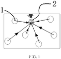
- FIG. 1 shows a schematic diagram of a voice synthesis device according to an embodiment of the present disclosure.
- the voice synthesis device comprises an aggregation node 2 and a plurality of detection nodes 1.
- Each of the plurality of detection nodes 1 may detect an external voice signal and send the detected voice signal to the aggregation node 2.
- the aggregation node 2 may receive the voice signals sent by the plurality of detection nodes 1 and determine whether each of the plurality of detection nodes 1 is trusted. Then, the aggregation node 2 may synthesize voice signals sent by detection nodes determined to be trusted to obtain a synthesized voice signal.
- detection nodes 1 determined to be trusted are referred to as trusted detection nodes.
- the detection nodes 1 may detect the external voice signals in real time and send the external voice signals to the aggregation node 2. Further, the detection nodes 1 may also receive a broadcast signal sent by the aggregation node 2, and send feedback signals to the aggregation node 2 after receiving the broadcast signal. The aggregation node 2 may periodically send the broadcast signal to each of the detection nodes 1, and receive the feedback signal from each of the detection nodes 1. After receiving the feedback signal from each of the plurality of detection nodes 1, the aggregation node 2 may determine a trust degree for each detection node 1, and determine whether the detection node 1 is trusted based on its determined trust degree.
- the aggregation node 2 synthesizes the external voice signals detected by the trusted detection nodes according to a determination result.
- the aggregation node 2 may filter the received voice signals and synthesize the voice signals sent by the trusted detection nodes.
- the bit error rate of voice signals may be reduced significantly, and the accuracy of voice signals may be improved.
- the aggregation node 2 may include a first wireless transceiver, a first program controller and a first voice sensing module.
- the first wireless transceiver may receive the voice signals sent by the plurality of detection nodes 1.
- the first wireless transceiver may periodically send the broadcast signal to each of the detection nodes 1, and receive the feedback signal from each of the detection nodes 1.
- the first wireless transceiver may be based on ZigBee wireless protocol. Those skilled in the art may also use any transceiver based on other wireless protocols.
- the first program controller may include a broadcast unit, a first reception unit, a detection unit and a synthesis unit.
- the broadcast unit may drive the aggregation node 2 to periodically send the broadcast signal to each of the detection nodes 1.
- the first reception unit may drive the aggregation node 2 to receive the feedback signal from each of the detection nodes 1.
- the detection unit may determine the trust degree for each of the detection nodes 1 according to the feedback signal, and determine whether the detection node 1 is trusted based on its trust degree.
- the synthesis unit may synthesize the external voice signals detected by trusted detection nodes according to determination results of the detection unit.
- the first program controller also comprises a voltage-stabilizing circuit.
- the first voice sensing module may transmit the synthesized voice signal to an external device.
- the first voice sensing module may be a piezoelectric vibration sensor. Those skilled in the art may also use any other type of module that can transmit voice signals to an external device.
- the detection node 1 may include a second voice sensing module, a second wireless transceiver and a second program controller.
- the second voice sensing module may detect the external voice signals.
- the second voice sensing module may be a piezoelectric vibration sensor.
- the second wireless transceiver may send the external voice signals detected by the second voice sensing module to the aggregation node 2.
- the second wireless transceiver may receive the broadcast signal sent by the aggregation node 2, and send the feedback signal to the aggregation node 2.
- the second wireless transceiver may be based on ZigBee wireless protocol.
- the second program controller may include a second reception unit and a transmission unit.
- the second reception unit may drive the detection node 1 to detect the external voice signals in real time, and drive the detection node 1 to receive the broadcast signal sent by the aggregation node 2.
- the transmission unit may drive the detection node 1 to transmit detected external voice signals to the aggregation node 2, and drive the detection node 1 to send the feedback signal to the aggregation node 2 after receiving the broadcast signal sent by the aggregation node 2.
- the second program controller may also include a voltage-stabilizing circuit.
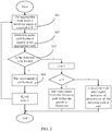
- FIG. 2 shows a voice synthesis method according to an embodiment of the present disclosure, which may be used in the voice synthesis device as shown in FIG. 1 .
- Step S01 the detection nodes 1 detect the external voice signals and transmit the external voice signals to the aggregation node 2.
- the aggregation node 2 receives the voice signals sent by a plurality of detection nodes 1.
- the aggregation node 2 periodically sends a broadcast signal to each of the detection nodes 1.
- a predetermined time T signifies a period in which the aggregation node 2 sends a broadcast signal to each of the detection nodes 1.
- Step S02 the detection nodes 1 receive the broadcast signal sent by the aggregation node 2. And the detection nodes 1 send feedback signals to the aggregation node 2 after receiving the broadcast signal.
- Step S03 the aggregation node 2 determines whether each of the plurality of detection nodes 1 is trusted. That is, after receiving the feedback signal from each of the detection nodes 1, the aggregation node 2 determines the trust degree for each detection node 1, and determines whether the detection node 1 is trusted based on the trust degree.
- the feedback signals adopt the external voice signals. However, those skilled in the art should know that the feedback signals may also adopt any other signals available for determining the trust degree for each detection node 1.
- the trust degree for the detection node is a ratio of an absolute value of difference between an external voice signal gathered by the detection node i and a mean value of external voice signals gathered by n detection nodes 1 to the foregoing mean values.
- the aggregation node 2 determines whether the detection node 1 is trusted based on the trust degree. If the trust degree K i ( t ) ⁇ a predefined threshold, the detection node i is not trusted at time t, and the external voice signal detected by the detection node i at time t is abandoned. If the trust degree K i ( t ) ⁇ the predefined threshold, the detection node i is trusted at time t, and the external voice signal detected by the detection node i at time t are available for aggregation node 2 to synthesize voice signals at time t.
- the predefined threshold may be 0.3, that is, if the trust degree for a detection node 1 is smaller than 0.3, it may be regarded that this detection node 1 is trusted, and thus voice signals detected by this detection node 1 may be available for the aggregation node 2 to synthesize voice signals at this moment.
- the aggregation node 2 sends a node error signal indicative of abnormality of the detection node k.
- Step S04 the aggregation node 2 synthesizes external voice signals sent by trusted detection nodes to obtain synthesized voice signals.
- the voice synthesis method of the embodiments of the present disclosure is strong in adaptability and high in reliability.
- FIG. 3 shows a schematic structural diagram of the voice synthesis device according to another embodiment of the present disclosure.
- the voice synthesis device in addition to the detection node 1 and the aggregation node 2, the voice synthesis device further comprises a central processing node 3 configured to receive synthesized voice signals transmitted by a plurality of aggregation nodes 2 and synthesize the synthesized voice signals received.
- the voice synthesis device comprises one central processing node 3, two aggregation nodes 2 (a first aggregation node 21 and a second aggregation node 22 respectively) and a plurality of detection nodes 1.
- the first aggregation node 21 and the second aggregation node 22 separately manage a plurality of detection nodes 1.
- Detection nodes 1 managed by the first aggregation node 21 transmit the detected external voice signals to the first aggregation node 21.
- Detection nodes 1 managed by the second aggregation node 22 transmit the external voice signals to the second aggregation node 22.
- the first aggregation node 21 synthesizes the voice signals transmitted by a plurality of detection nodes 1 managed by the first aggregation node 21, and transmits the synthesized voice signal to the central processing node 3.
- the second aggregation node 22 synthesizes the voice signals transmitted by a plurality of detection nodes 1 managed by the second aggregation node 22, and transmits the synthesized voice signal to the central processing node 3.
- the central processing node 3 synthesizes the synthesized voice signals transmitted by the first aggregation node 21 and the second aggregation node 22.
- FIG. 4 shows a flowchart of the voice synthesis method according to another embodiment of the present disclosure, which may be used in the voice synthesis device as shown in FIG. 3 .
- a process in synthesizing voice signals from detection nodes 1 managed by the first aggregation node 21 and the second aggregation node 22 is the same as the voice synthesis method of the embodiment as shown in FIG. 2 , and thus a description thereof is omitted herein.
- the first aggregation node 21 and the second aggregation node 22 synthesize voice signals of detection nodes 1 respectively managed by them, they separately transmit the synthesized voice signals to the central processing node 3.
- the central processing node 3 further synthesizes the synthesized voice signals transmitted by the first aggregation node 21 and the second aggregation node 22 to serve as a final synthesized voice signal.
- i denotes any detection node 1 among n detection nodes 1 managed by the first aggregation node
- j denotes any detection node 1 among m detection nodes 1 managed by the second aggregation node 22.
- k denotes a detection node determined to be untrusted at time t and managed by the first aggregation node
- p denotes a detection node determined to be untrusted at time t and managed by the second aggregation node 21.
- the embodiments of the present disclosure are described by taking one aggregation node or two aggregation nodes as an example, it is easily conceivable for a person skilled in the art that the voice synthesis device may also include more aggregation nodes, and each aggregation node may manage a plurality of detection nodes and synthesize voice signals from all of the managed detection nodes.
- a process of utilizing one central processing node to further comprehensively process voice signals synthesized by a plurality of aggregation nodes is described.
- a plurality of central processing nodes may also be used for processing.
- FIG. 5 shows a schematic structural diagram of a bone conduction helmet according to an embodiment of the present disclosure.
- the bone conduction helmet may include a helmet body and the voice synthesis device disposed on the helmet body.
- the aggregation node may be disposed on the helmet body of the bone conduction helmet, and the detection nodes are dispersedly disposed on the helmet body of the bone conduction helmet.
- the voice synthesis device comprises a plurality of aggregation nodes
- the aggregation nodes may be dispersedly disposed on the helmet body.
- the voice synthesis device further comprises a central processing node
- the central processing node may also be disposed on the helmet body of the bone conduction helmet.
- embodiments of the present disclosure further provide a hearing aid, comprising the voice synthesis device described in the foregoing embodiments.
Landscapes
- Engineering & Computer Science (AREA)
- Physics & Mathematics (AREA)
- Acoustics & Sound (AREA)
- Signal Processing (AREA)
- Health & Medical Sciences (AREA)
- Multimedia (AREA)
- Human Computer Interaction (AREA)
- Audiology, Speech & Language Pathology (AREA)
- Computational Linguistics (AREA)
- General Health & Medical Sciences (AREA)
- Otolaryngology (AREA)
- Neurosurgery (AREA)
- Circuit For Audible Band Transducer (AREA)
- Telephonic Communication Services (AREA)
- Measurement Of The Respiration, Hearing Ability, Form, And Blood Characteristics Of Living Organisms (AREA)
- Mobile Radio Communication Systems (AREA)
Claims (13)
- Sprachsynthesevorrichtung mit
einer Anzahl Erkennungsknoten (1), die dazu ausgelegt sind, Sprachsignale zu erkennen, und
einem Aggregationsknoten (2), der dazu ausgelegt ist, die von der Anzahl Erkennungsknoten (1) abgesandten Sprachsignale zu empfangen, um zu bestimmen, ob jeder der Anzahl Erkennungsknoten (1) zuverlässig ist, und um die von den Erkennungsknoten (1), die als zuverlässig erachtet worden sind, abgesandten Sprachsignale zu synthetisieren, um synthetisierte Sprachsignale zu erhalten,
dadurch gekennzeichnet,
daß jeder der Anzahl Erkennungsknoten (1) außerdem dazu ausgelegt ist, als Antwort auf den Empfang eines vom Aggregationsknoten (2) abgesandten Sendesignals ein Antwortsignal an den Aggregationsknoten (2) zu senden, und daß der Aggregationsknoten (2) des Weiteren dazu ausgelegt ist, das Sendesignal an die Anzahl Erkennungsknoten (1) zu senden, um als Antwort auf den Empfang des Antwortsignals von jedem der Erkennungsknoten (1) für jeden der Erkennungsknoten (1) einen Zuverlässigkeitsgrad zu bestimmen und um zu bestimmen, ob jeder der Anzahl Erkennungsknoten (1) auf Grund seines Zuverlässigkeitsgrads zuverlässig ist,
wobei der Zuverlässigkeitsgrad für die Erkennungsknoten (1) als
wobei Ki(t) den Zuverlässigkeitsgrad für einen Erkennungsknoten (1) i zum Zeitpunkt t bezeichnet, n die Ordnungszahl der Anzahl Erkennungsknoten (1) bezeichnet und Yi(t) ein vom Erkennungsknoten (1) i zum Zeitpunkt t erkanntes Sprachsignal als Antwortsignal bezeichnet,
wobei der Zuverlässigkeitsgrad mit einem vorbestimmten Schwellwert verglichen wird und
wobei als Antwort, wenn der Zuverlässigkeitsgrad Ki(t) größer als oder gleich dem vorbestimmten Schwellwert ist, bestimmt wird, daß der Erkennungsknoten (1) i zum Zeitpunkt t nicht zuverlässig ist und, wenn der Zuverlässigkeitsgrad Ki(t) kleiner als der vorbestimmte Schwellwert ist, bestimmt wird, daß der Erkennungsknoten (1) i zum Zeitpunkt t zuverlässig ist. - Sprachsynthesevorrichtung gemäß Anspruch 1, dadurch gekennzeichnet, daß die Sprachsynthesevorrichtung außerdem einen zentralen Verarbeitungsknoten aufweist, der dazu ausgelegt ist, das von einer Anzahl Aggregationsknoten (2) übertragene synthetisierte Sprachsignal zu empfangen und die empfangenen synthetisierten Sprachsignale zu synthetisieren.
- Sprachsynthesevorrichtung gemäß Anspruch 1 oder 2, dadurch gekennzeichnet, daß der Aggregationsknoten (2)
ein erstes drahtloses Sende-Empfangsgerät, das dazu ausgelegt ist, die von der Anzahl Erkennungsknoten (1) abgesandten Sprachsignale zu empfangen, und
eine erste Programmsteuerung, die dazu ausgelegt ist, zu bestimmen, ob jeder der Anzahl Erkennungsknoten (1) zuverlässig ist, und um die von der Anzahl Erkennungsknoten (1), die als zuverlässig erachtet worden sind, das synthetisierte Sprachsignal zu erhalten, abgesandten Sprachsignale zu synthetisieren, aufweist,
wobei die erste Programmsteuerung vorzugsweise einen spannungsstabilisierenden Schaltkreis aufweist,
wobei das erste drahtlose Sende-Empfangsgerät vorzugsweise auf einem drahtlosen ZigBee-Protokoll basiert. - Sprachsynthesevorrichtung gemäß Anspruch 3, dadurch gekennzeichnet,
daß das erste drahtlose Sende-Empfangsgerät außerdem dazu ausgelegt ist, das Sendesignal an die Anzahl Erkennungsknoten (1) zu senden und das Antwortsignal von jedem der Anzahl Erkennungsknoten (1) zu empfangen, und
daß die erste Programmsteuerung außerdem dazu ausgelegt ist, den Zuverlässigkeitsgrad für jeden der Anzahl Erkennungsknoten (1) zu bestimmen und zu bestimmen, ob der Erkennungsknoten (1) auf Grund seines Zuverlässigkeitsgrads zuverlässig ist. - Sprachsynthesevorrichtung gemäß Anspruch 3 oder 4, dadurch gekennzeichnet, daß der Aggregationsknoten (2) außerdem
ein erstes Spracherfassungsmodul aufweist, das dazu ausgelegt ist, das synthetisierte Sprachsignal an den zentralen Verarbeitungsknoten zu übertragen. - Sprachsynthesevorrichtung gemäß Anspruch 1, dadurch gekennzeichnet, daß der Erkennungsknoten (1)
ein zweites Spracherfassungsmodul, das dazu ausgelegt ist, das Sprachsignal zu erkennen, und
ein zweites drahtloses Sende-Empfangsgerät, das dazu ausgelegt ist, das vom zweiten Spracherfassungsmodul erkannte Sprachsignal an den Aggregationsknoten (2) zu senden,
aufweist,
wobei das zweite drahtlose Sende-Empfangsgerät vorzugsweise auf einem drahtlosen ZigBee-Protokoll basiert,
wobei das zweite Spracherfassungsmodul vorzugsweise ein piezoelektrischer Vibrationssensor ist. - Sprachsynthesevorrichtung gemäß Anspruch 6, dadurch gekennzeichnet, daß das zweite drahtlose Sende-Empfangsgerät außerdem dazu ausgelegt ist, das vom Aggregationsknoten (2) gesandte Sendesignal zu empfangen und das Antwortsignal an den Aggregationsknoten (2) zu senden.
- Sprachsyntheseverfahren mit
Empfangen von durch eine Anzahl Erkennungsknoten (1) abgesandten Sprachsignalen,
Bestimmen, ob jeder der Anzahl Erkennungsknoten (1) zuverlässig ist, und Synthetisieren der durch die Erkennungsknoten (1), die als zuverlässig erachtet worden sind, ein synthetisiertes Sprachsignal zu erhalten, abgesandten Sprachsignale,
dadurch gekennzeichnet, daß
Bestimmen, ob die Anzahl Erkennungsknoten (1) zuverlässig ist,Absenden (S01) eines Sendesignals an die Anzahl Erkennungsknoten (1), Bestimmen eines Zuverlässigkeitsgrads für jeden der Erkennungsknoten (1) als Antwort auf das Empfangen eines Antwortsignals von jedem der Erkennungsknoten (1) undBestimmen (S03), ob jeder der Anzahl Erkennungsknoten (1) auf Grund seines Zuverlässigkeitsgrads zuverlässig ist,aufweist,
wobei der Zuverlässigkeitsgrad für die Erkennungsknoten (1) als
wobei Ki(t) den Zuverlässigkeitsgrad für einen Erkennungsknoten (1) i zum Zeitpunkt t bezeichnet, n die Ordnungszahl der Anzahl Erkennungsknoten (1) bezeichnet und Yi(t) ein vom Erkennungsknoten (1) i zum Zeitpunkt t erkanntes Sprachsignal als Antwortsignal bezeichnet,
wobei Bestimmen, ob jeder der Anzahl Erkennungsknoten (1) auf Grund seines Zuverlässigkeitsgrads zuverlässig ist,Vergleichen des Zuverlässigkeitsgrads mit einem vorbestimmten Schwellwert undals Antwort, wenn der Zuverlässigkeitsgrad Ki(t) größer als oder gleich dem vorbestimmten Schwellwert ist, Bestimmen, daß der Erkennungsknoten (1) i zum Zeitpunkt t nicht zuverlässig ist und, wenn der Zuverlässigkeitsgrad Ki(t) kleiner als der vorbestimmte Schwellwert ist, Bestimmen, daß der Erkennungsknoten (1) i zum Zeitpunkt t zuverlässig ist,aufweist. - Sprachsyntheseverfahren gemäß Anspruch 8, dadurch gekennzeichnet, daß das Sprachsyntheseverfahren außerdem
Übersenden des synthetisierten Sprachsignals an einen zentralen Verarbeitungsknoten
aufweist. - Sprachsyntheseverfahren gemäß Anspruch 9, dadurch gekennzeichnet, daß das Sprachsyntheseverfahren außerdem
als Antwort in all den Fällen, in denen der Erkennungsknoten nicht als zuverlässig erachtet worden ist, einen vorbestimmten Wert zu erreichen, das Aussenden eines Knotenfehlersignals aufweist, das auf den unnormalen Zustand des Erkennungsknotens (1) hinweist. - Sprachsyntheseverfahren gemäß Anspruch 10, dadurch gekennzeichnet, daß das Synthetisieren des von den Erkennungsknoten (1), die als zuverlässig erachtet worden sind, abgesandten Sprachsignals
Berechnen einer Wichtung des Sprachsignals von jedem der zuverlässigen Erkennungsknoten (1) als
Synthetisieren der von den zuverlässigen Erkennungsknoten (1) kommenden Sprachsignale, um das synthetisierte Sprachsignal wie folgt zu erhalten;
wobei der Schwellwert vorzugsweise 0,3 beträgt,
aufweist. - Knochenleitungshelm dadurch gekennzeichnet, daß der Knochenleitungshelm einen Helmkörper und die Sprachsynthesevorrichtung gemäß einem der Ansprüche 1 bis 7, die auf dem Helmkörper angeordnet ist, aufweist,
wobei vorzugsweise eine Anzahl Erkennungsknoten (1) in der Sprachsynthesevorrichtung auf dem Helmkörper verstreut angeordnet sind. - Hörgerät, dadurch gekennzeichnet, daß das Hörgerät die Sprachsynthesevorrichtung gemäß einem der Ansprüche 1 bis 7 aufweist.
Applications Claiming Priority (2)
| Application Number | Priority Date | Filing Date | Title |
|---|---|---|---|
| CN201510358985.XA CN105185371B (zh) | 2015-06-25 | 2015-06-25 | 一种语音合成装置、语音合成方法、骨传导头盔和助听器 |
| PCT/CN2015/094438 WO2016206285A1 (zh) | 2015-06-25 | 2015-11-12 | 语音合成装置、语音合成方法、骨传导头盔和助听器 |
Publications (3)
| Publication Number | Publication Date |
|---|---|
| EP3316253A1 EP3316253A1 (de) | 2018-05-02 |
| EP3316253A4 EP3316253A4 (de) | 2019-02-27 |
| EP3316253B1 true EP3316253B1 (de) | 2020-08-12 |
Family
ID=54907399
Family Applications (1)
| Application Number | Title | Priority Date | Filing Date |
|---|---|---|---|
| EP15864302.3A Active EP3316253B1 (de) | 2015-06-25 | 2015-11-12 | Sprachsynthesevorrichtung, sprachsyntheseverfahren, knochenleitungshelm und hörgerät |
Country Status (4)
| Country | Link |
|---|---|
| US (1) | US10255902B2 (de) |
| EP (1) | EP3316253B1 (de) |
| CN (1) | CN105185371B (de) |
| WO (1) | WO2016206285A1 (de) |
Families Citing this family (2)
| Publication number | Priority date | Publication date | Assignee | Title |
|---|---|---|---|---|
| EP3737115A1 (de) | 2019-05-06 | 2020-11-11 | GN Hearing A/S | Hörgerät mit knochenleitungssensor |
| CN115285268B (zh) * | 2022-09-01 | 2024-05-28 | 重庆三三电器股份有限公司 | 基于Carlife的智能语音仪表的控制和交互方法 |
Family Cites Families (20)
| Publication number | Priority date | Publication date | Assignee | Title |
|---|---|---|---|---|
| DE69233156T2 (de) * | 1991-01-17 | 2004-07-08 | Adelman, Roger A. | Verbessertes hörgerät |
| JP2002227025A (ja) | 2001-01-30 | 2002-08-14 | Asia Guroobu:Kk | ヘルメット |
| US20060277664A1 (en) | 2004-07-26 | 2006-12-14 | Saman Rahila Akhtar | Multifunctional helmet |
| DK2066140T3 (en) * | 2007-11-28 | 2016-04-18 | Oticon Medical As | Method of mounting a bone anchored hearing aid for a user and bone anchored bone conducting hearing system. |
| CN101753221A (zh) * | 2008-11-28 | 2010-06-23 | 新兴盛科技股份有限公司 | 蝶颞骨传导通讯与/或助听装置 |
| US20100223706A1 (en) | 2009-03-03 | 2010-09-09 | Illinois Tool Works Inc. | Welding helmet audio communication systems and methods with bone conduction transducers |
| DK2309777T3 (da) * | 2009-09-14 | 2013-02-04 | Gn Resound As | Et høreapparat med organer til at de-korrelere indgangs- og udgangssignaler |
| KR200460404Y1 (ko) | 2009-11-06 | 2012-05-24 | 이준환 | 골전도 진동자를 이용한 조종사용 헬멧 |
| DK2378793T3 (da) * | 2010-04-14 | 2013-05-13 | Gn Resound As | Høreindretning, der er konfigureret til trådløs kommunikation i bursts, og en fremgangsmåde til levering af strøm til denne |
| US8798992B2 (en) * | 2010-05-19 | 2014-08-05 | Disney Enterprises, Inc. | Audio noise modification for event broadcasting |
| US9711127B2 (en) * | 2011-09-19 | 2017-07-18 | Bitwave Pte Ltd. | Multi-sensor signal optimization for speech communication |
| US9185501B2 (en) * | 2012-06-20 | 2015-11-10 | Broadcom Corporation | Container-located information transfer module |
| CN102930864A (zh) | 2012-11-26 | 2013-02-13 | 江苏物联网研究发展中心 | 基于子节点的声联网音信息关键词挖掘系统 |
| WO2014094858A1 (en) * | 2012-12-20 | 2014-06-26 | Widex A/S | Hearing aid and a method for improving speech intelligibility of an audio signal |
| JP6519877B2 (ja) | 2013-02-26 | 2019-05-29 | 聯發科技股▲ふん▼有限公司Mediatek Inc. | 音声信号を発生するための方法及び装置 |
| KR20140127508A (ko) * | 2013-04-25 | 2014-11-04 | 삼성전자주식회사 | 음성처리장치 및 음성처리방법 |
| CN103533123B (zh) | 2013-09-23 | 2018-04-06 | 陕西烽火电子股份有限公司 | 一种飞机用多接收通道通话静噪方法 |
| US9467765B2 (en) * | 2013-10-22 | 2016-10-11 | Gn Resound A/S | Hearing instrument with interruptable microphone power supply |
| DK201370793A1 (en) * | 2013-12-19 | 2015-06-29 | Gn Resound As | A hearing aid system with selectable perceived spatial positioning of sound sources |
| CN104116262B (zh) | 2014-06-26 | 2015-12-02 | 浙江东昂电子科技有限公司 | 骨传导无线通信头盔 |
-
2015
- 2015-06-25 CN CN201510358985.XA patent/CN105185371B/zh active Active
- 2015-11-12 US US15/181,069 patent/US10255902B2/en active Active
- 2015-11-12 WO PCT/CN2015/094438 patent/WO2016206285A1/zh not_active Ceased
- 2015-11-12 EP EP15864302.3A patent/EP3316253B1/de active Active
Non-Patent Citations (1)
| Title |
|---|
| None * |
Also Published As
| Publication number | Publication date |
|---|---|
| WO2016206285A1 (zh) | 2016-12-29 |
| US10255902B2 (en) | 2019-04-09 |
| CN105185371A (zh) | 2015-12-23 |
| EP3316253A4 (de) | 2019-02-27 |
| EP3316253A1 (de) | 2018-05-02 |
| CN105185371B (zh) | 2017-07-11 |
| US20180190261A1 (en) | 2018-07-05 |
Similar Documents
| Publication | Publication Date | Title |
|---|---|---|
| US11869505B2 (en) | Local artificial intelligence assistant system with ear-wearable device | |
| EP3410744B1 (de) | Verfahren zur auswahl der übertragungsrichtung in einer binauralen hörhilfe | |
| US9877116B2 (en) | Hearing device with position data, audio system and related methods | |
| EP2882203A1 (de) | Hörgerätevorrichtung für freihändige Kommunikation | |
| EP4000281B1 (de) | Hörgeräte mit proxyvorrichtungen für notfallkommunikation | |
| AU2015349054A1 (en) | Method and apparatus for fast recognition of a user's own voice | |
| US20200219515A1 (en) | Audio signal processing for automatic transcription using ear-wearable device | |
| CN110876099B (zh) | 无线音频系统和用于使第一耳机和第二耳机同步的方法 | |
| JP6674737B2 (ja) | 位置データを有する聴取装置および聴取装置の動作方法 | |
| EP3316253B1 (de) | Sprachsynthesevorrichtung, sprachsyntheseverfahren, knochenleitungshelm und hörgerät | |
| CN113825078B (zh) | 具有听力设备的听力系统和用于运行这种听力系统的方法 | |
| US20150172829A1 (en) | Method of determining a fit of a hearing device and hearing device with fit recognition | |
| CN104936096B (zh) | 骨导声音传播装置和方法 | |
| US11259130B2 (en) | Hearing assistive system with sensors | |
| US20240381037A1 (en) | Methods and systems for evaluating hearing threshold of user after using bone-conduction hearing aid | |
| US20240377430A1 (en) | Binaural hearing system with distributed sensors, and method of its operation | |
| US9565499B2 (en) | Binaural hearing aid system for compensation of microphone deviations based on the wearer's own voice | |
| EP4117311A1 (de) | Verfahren und system zur erkennung des zustands einer knochenleitungshörvorrichtung | |
| JP5814960B2 (ja) | 電子体温計、受信装置及び電子体温計システム | |
| EP2890156A1 (de) | Hörgerät mit Positionsdaten und Verfahren zum Betrieb eines Hörgeräts | |
| EP4553532A1 (de) | System zur lokalisierung eines audioereignisses | |
| EP3618458B1 (de) | Hörgerät mit positionsdaten, audiosystem und zugehörige verfahren | |
| DK201370827A1 (en) | Hearing device with position data and method of operating a hearing device | |
| JP2013187798A (ja) | 補聴器警報システム |
Legal Events
| Date | Code | Title | Description |
|---|---|---|---|
| STAA | Information on the status of an ep patent application or granted ep patent |
Free format text: STATUS: THE INTERNATIONAL PUBLICATION HAS BEEN MADE |
|
| PUAI | Public reference made under article 153(3) epc to a published international application that has entered the european phase |
Free format text: ORIGINAL CODE: 0009012 |
|
| STAA | Information on the status of an ep patent application or granted ep patent |
Free format text: STATUS: REQUEST FOR EXAMINATION WAS MADE |
|
| 17P | Request for examination filed |
Effective date: 20160606 |
|
| AK | Designated contracting states |
Kind code of ref document: A1 Designated state(s): AL AT BE BG CH CY CZ DE DK EE ES FI FR GB GR HR HU IE IS IT LI LT LU LV MC MK MT NL NO PL PT RO RS SE SI SK SM TR |
|
| AX | Request for extension of the european patent |
Extension state: BA ME |
|
| DAV | Request for validation of the european patent (deleted) | ||
| DAX | Request for extension of the european patent (deleted) | ||
| R17P | Request for examination filed (corrected) |
Effective date: 20160606 |
|
| A4 | Supplementary search report drawn up and despatched |
Effective date: 20190129 |
|
| RIC1 | Information provided on ipc code assigned before grant |
Ipc: G10L 13/02 20130101AFI20190123BHEP Ipc: H04R 1/10 20060101ALN20190123BHEP Ipc: A42B 3/30 20060101ALI20190123BHEP Ipc: H04B 1/3827 20150101ALN20190123BHEP Ipc: H04R 25/00 20060101ALI20190123BHEP Ipc: G10L 25/84 20130101ALI20190123BHEP Ipc: H04R 3/00 20060101ALI20190123BHEP |
|
| STAA | Information on the status of an ep patent application or granted ep patent |
Free format text: STATUS: EXAMINATION IS IN PROGRESS |
|
| 17Q | First examination report despatched |
Effective date: 20191028 |
|
| GRAP | Despatch of communication of intention to grant a patent |
Free format text: ORIGINAL CODE: EPIDOSNIGR1 |
|
| STAA | Information on the status of an ep patent application or granted ep patent |
Free format text: STATUS: GRANT OF PATENT IS INTENDED |
|
| RIC1 | Information provided on ipc code assigned before grant |
Ipc: G10L 25/84 20130101ALI20200406BHEP Ipc: H04R 1/10 20060101ALN20200406BHEP Ipc: H04B 1/3827 20150101ALN20200406BHEP Ipc: A42B 3/30 20060101ALI20200406BHEP Ipc: H04R 3/00 20060101ALI20200406BHEP Ipc: G10L 13/02 20130101AFI20200406BHEP Ipc: H04R 25/00 20060101ALI20200406BHEP |
|
| INTG | Intention to grant announced |
Effective date: 20200423 |
|
| GRAS | Grant fee paid |
Free format text: ORIGINAL CODE: EPIDOSNIGR3 |
|
| GRAA | (expected) grant |
Free format text: ORIGINAL CODE: 0009210 |
|
| STAA | Information on the status of an ep patent application or granted ep patent |
Free format text: STATUS: THE PATENT HAS BEEN GRANTED |
|
| AK | Designated contracting states |
Kind code of ref document: B1 Designated state(s): AL AT BE BG CH CY CZ DE DK EE ES FI FR GB GR HR HU IE IS IT LI LT LU LV MC MK MT NL NO PL PT RO RS SE SI SK SM TR |
|
| REG | Reference to a national code |
Ref country code: CH Ref legal event code: EP |
|
| REG | Reference to a national code |
Ref country code: IE Ref legal event code: FG4D |
|
| REG | Reference to a national code |
Ref country code: DE Ref legal event code: R096 Ref document number: 602015057510 Country of ref document: DE |
|
| REG | Reference to a national code |
Ref country code: AT Ref legal event code: REF Ref document number: 1302324 Country of ref document: AT Kind code of ref document: T Effective date: 20200915 |
|
| REG | Reference to a national code |
Ref country code: LT Ref legal event code: MG4D |
|
| REG | Reference to a national code |
Ref country code: NL Ref legal event code: MP Effective date: 20200812 |
|
| PG25 | Lapsed in a contracting state [announced via postgrant information from national office to epo] |
Ref country code: GR Free format text: LAPSE BECAUSE OF FAILURE TO SUBMIT A TRANSLATION OF THE DESCRIPTION OR TO PAY THE FEE WITHIN THE PRESCRIBED TIME-LIMIT Effective date: 20201113 Ref country code: NO Free format text: LAPSE BECAUSE OF FAILURE TO SUBMIT A TRANSLATION OF THE DESCRIPTION OR TO PAY THE FEE WITHIN THE PRESCRIBED TIME-LIMIT Effective date: 20201112 Ref country code: BG Free format text: LAPSE BECAUSE OF FAILURE TO SUBMIT A TRANSLATION OF THE DESCRIPTION OR TO PAY THE FEE WITHIN THE PRESCRIBED TIME-LIMIT Effective date: 20201112 Ref country code: LT Free format text: LAPSE BECAUSE OF FAILURE TO SUBMIT A TRANSLATION OF THE DESCRIPTION OR TO PAY THE FEE WITHIN THE PRESCRIBED TIME-LIMIT Effective date: 20200812 Ref country code: HR Free format text: LAPSE BECAUSE OF FAILURE TO SUBMIT A TRANSLATION OF THE DESCRIPTION OR TO PAY THE FEE WITHIN THE PRESCRIBED TIME-LIMIT Effective date: 20200812 Ref country code: SE Free format text: LAPSE BECAUSE OF FAILURE TO SUBMIT A TRANSLATION OF THE DESCRIPTION OR TO PAY THE FEE WITHIN THE PRESCRIBED TIME-LIMIT Effective date: 20200812 Ref country code: FI Free format text: LAPSE BECAUSE OF FAILURE TO SUBMIT A TRANSLATION OF THE DESCRIPTION OR TO PAY THE FEE WITHIN THE PRESCRIBED TIME-LIMIT Effective date: 20200812 |
|
| REG | Reference to a national code |
Ref country code: AT Ref legal event code: MK05 Ref document number: 1302324 Country of ref document: AT Kind code of ref document: T Effective date: 20200812 |
|
| PG25 | Lapsed in a contracting state [announced via postgrant information from national office to epo] |
Ref country code: LV Free format text: LAPSE BECAUSE OF FAILURE TO SUBMIT A TRANSLATION OF THE DESCRIPTION OR TO PAY THE FEE WITHIN THE PRESCRIBED TIME-LIMIT Effective date: 20200812 Ref country code: RS Free format text: LAPSE BECAUSE OF FAILURE TO SUBMIT A TRANSLATION OF THE DESCRIPTION OR TO PAY THE FEE WITHIN THE PRESCRIBED TIME-LIMIT Effective date: 20200812 Ref country code: PL Free format text: LAPSE BECAUSE OF FAILURE TO SUBMIT A TRANSLATION OF THE DESCRIPTION OR TO PAY THE FEE WITHIN THE PRESCRIBED TIME-LIMIT Effective date: 20200812 Ref country code: NL Free format text: LAPSE BECAUSE OF FAILURE TO SUBMIT A TRANSLATION OF THE DESCRIPTION OR TO PAY THE FEE WITHIN THE PRESCRIBED TIME-LIMIT Effective date: 20200812 Ref country code: IS Free format text: LAPSE BECAUSE OF FAILURE TO SUBMIT A TRANSLATION OF THE DESCRIPTION OR TO PAY THE FEE WITHIN THE PRESCRIBED TIME-LIMIT Effective date: 20201212 |
|
| PG25 | Lapsed in a contracting state [announced via postgrant information from national office to epo] |
Ref country code: SM Free format text: LAPSE BECAUSE OF FAILURE TO SUBMIT A TRANSLATION OF THE DESCRIPTION OR TO PAY THE FEE WITHIN THE PRESCRIBED TIME-LIMIT Effective date: 20200812 Ref country code: RO Free format text: LAPSE BECAUSE OF FAILURE TO SUBMIT A TRANSLATION OF THE DESCRIPTION OR TO PAY THE FEE WITHIN THE PRESCRIBED TIME-LIMIT Effective date: 20200812 Ref country code: EE Free format text: LAPSE BECAUSE OF FAILURE TO SUBMIT A TRANSLATION OF THE DESCRIPTION OR TO PAY THE FEE WITHIN THE PRESCRIBED TIME-LIMIT Effective date: 20200812 Ref country code: DK Free format text: LAPSE BECAUSE OF FAILURE TO SUBMIT A TRANSLATION OF THE DESCRIPTION OR TO PAY THE FEE WITHIN THE PRESCRIBED TIME-LIMIT Effective date: 20200812 Ref country code: CZ Free format text: LAPSE BECAUSE OF FAILURE TO SUBMIT A TRANSLATION OF THE DESCRIPTION OR TO PAY THE FEE WITHIN THE PRESCRIBED TIME-LIMIT Effective date: 20200812 |
|
| REG | Reference to a national code |
Ref country code: DE Ref legal event code: R097 Ref document number: 602015057510 Country of ref document: DE |
|
| PG25 | Lapsed in a contracting state [announced via postgrant information from national office to epo] |
Ref country code: AL Free format text: LAPSE BECAUSE OF FAILURE TO SUBMIT A TRANSLATION OF THE DESCRIPTION OR TO PAY THE FEE WITHIN THE PRESCRIBED TIME-LIMIT Effective date: 20200812 Ref country code: AT Free format text: LAPSE BECAUSE OF FAILURE TO SUBMIT A TRANSLATION OF THE DESCRIPTION OR TO PAY THE FEE WITHIN THE PRESCRIBED TIME-LIMIT Effective date: 20200812 Ref country code: ES Free format text: LAPSE BECAUSE OF FAILURE TO SUBMIT A TRANSLATION OF THE DESCRIPTION OR TO PAY THE FEE WITHIN THE PRESCRIBED TIME-LIMIT Effective date: 20200812 |
|
| PLBE | No opposition filed within time limit |
Free format text: ORIGINAL CODE: 0009261 |
|
| STAA | Information on the status of an ep patent application or granted ep patent |
Free format text: STATUS: NO OPPOSITION FILED WITHIN TIME LIMIT |
|
| PG25 | Lapsed in a contracting state [announced via postgrant information from national office to epo] |
Ref country code: SK Free format text: LAPSE BECAUSE OF FAILURE TO SUBMIT A TRANSLATION OF THE DESCRIPTION OR TO PAY THE FEE WITHIN THE PRESCRIBED TIME-LIMIT Effective date: 20200812 Ref country code: MC Free format text: LAPSE BECAUSE OF FAILURE TO SUBMIT A TRANSLATION OF THE DESCRIPTION OR TO PAY THE FEE WITHIN THE PRESCRIBED TIME-LIMIT Effective date: 20200812 |
|
| REG | Reference to a national code |
Ref country code: CH Ref legal event code: PL |
|
| 26N | No opposition filed |
Effective date: 20210514 |
|
| GBPC | Gb: european patent ceased through non-payment of renewal fee |
Effective date: 20201112 |
|
| PG25 | Lapsed in a contracting state [announced via postgrant information from national office to epo] |
Ref country code: IT Free format text: LAPSE BECAUSE OF FAILURE TO SUBMIT A TRANSLATION OF THE DESCRIPTION OR TO PAY THE FEE WITHIN THE PRESCRIBED TIME-LIMIT Effective date: 20200812 Ref country code: LU Free format text: LAPSE BECAUSE OF NON-PAYMENT OF DUE FEES Effective date: 20201112 |
|
| REG | Reference to a national code |
Ref country code: BE Ref legal event code: MM Effective date: 20201130 |
|
| PG25 | Lapsed in a contracting state [announced via postgrant information from national office to epo] |
Ref country code: CH Free format text: LAPSE BECAUSE OF NON-PAYMENT OF DUE FEES Effective date: 20201130 Ref country code: LI Free format text: LAPSE BECAUSE OF NON-PAYMENT OF DUE FEES Effective date: 20201130 Ref country code: SI Free format text: LAPSE BECAUSE OF FAILURE TO SUBMIT A TRANSLATION OF THE DESCRIPTION OR TO PAY THE FEE WITHIN THE PRESCRIBED TIME-LIMIT Effective date: 20200812 |
|
| PG25 | Lapsed in a contracting state [announced via postgrant information from national office to epo] |
Ref country code: FR Free format text: LAPSE BECAUSE OF NON-PAYMENT OF DUE FEES Effective date: 20201130 Ref country code: IE Free format text: LAPSE BECAUSE OF NON-PAYMENT OF DUE FEES Effective date: 20201112 |
|
| PG25 | Lapsed in a contracting state [announced via postgrant information from national office to epo] |
Ref country code: GB Free format text: LAPSE BECAUSE OF NON-PAYMENT OF DUE FEES Effective date: 20201112 |
|
| PG25 | Lapsed in a contracting state [announced via postgrant information from national office to epo] |
Ref country code: IS Free format text: LAPSE BECAUSE OF FAILURE TO SUBMIT A TRANSLATION OF THE DESCRIPTION OR TO PAY THE FEE WITHIN THE PRESCRIBED TIME-LIMIT Effective date: 20201212 Ref country code: TR Free format text: LAPSE BECAUSE OF FAILURE TO SUBMIT A TRANSLATION OF THE DESCRIPTION OR TO PAY THE FEE WITHIN THE PRESCRIBED TIME-LIMIT Effective date: 20200812 Ref country code: MT Free format text: LAPSE BECAUSE OF FAILURE TO SUBMIT A TRANSLATION OF THE DESCRIPTION OR TO PAY THE FEE WITHIN THE PRESCRIBED TIME-LIMIT Effective date: 20200812 Ref country code: CY Free format text: LAPSE BECAUSE OF FAILURE TO SUBMIT A TRANSLATION OF THE DESCRIPTION OR TO PAY THE FEE WITHIN THE PRESCRIBED TIME-LIMIT Effective date: 20200812 |
|
| PG25 | Lapsed in a contracting state [announced via postgrant information from national office to epo] |
Ref country code: MK Free format text: LAPSE BECAUSE OF FAILURE TO SUBMIT A TRANSLATION OF THE DESCRIPTION OR TO PAY THE FEE WITHIN THE PRESCRIBED TIME-LIMIT Effective date: 20200812 |
|
| PG25 | Lapsed in a contracting state [announced via postgrant information from national office to epo] |
Ref country code: PT Free format text: LAPSE BECAUSE OF FAILURE TO SUBMIT A TRANSLATION OF THE DESCRIPTION OR TO PAY THE FEE WITHIN THE PRESCRIBED TIME-LIMIT Effective date: 20200812 Ref country code: BE Free format text: LAPSE BECAUSE OF NON-PAYMENT OF DUE FEES Effective date: 20201130 |
|
| PGFP | Annual fee paid to national office [announced via postgrant information from national office to epo] |
Ref country code: DE Payment date: 20251121 Year of fee payment: 11 |