EP3316402A1 - Douille de contact plate - Google Patents
Douille de contact plate Download PDFInfo
- Publication number
- EP3316402A1 EP3316402A1 EP17151499.5A EP17151499A EP3316402A1 EP 3316402 A1 EP3316402 A1 EP 3316402A1 EP 17151499 A EP17151499 A EP 17151499A EP 3316402 A1 EP3316402 A1 EP 3316402A1
- Authority
- EP
- European Patent Office
- Prior art keywords
- flat contact
- socket
- connection
- extensions
- electrical
- Prior art date
- Legal status (The legal status is an assumption and is not a legal conclusion. Google has not performed a legal analysis and makes no representation as to the accuracy of the status listed.)
- Granted
Links
Images

Classifications
-
- H—ELECTRICITY
- H01—ELECTRIC ELEMENTS
- H01R—ELECTRICALLY-CONDUCTIVE CONNECTIONS; STRUCTURAL ASSOCIATIONS OF A PLURALITY OF MUTUALLY-INSULATED ELECTRICAL CONNECTING ELEMENTS; COUPLING DEVICES; CURRENT COLLECTORS
- H01R13/00—Details of coupling devices of the kinds covered by groups H01R12/70 or H01R24/00 - H01R33/00
- H01R13/40—Securing contact members in or to a base or case; Insulating of contact members
-
- H—ELECTRICITY
- H01—ELECTRIC ELEMENTS
- H01R—ELECTRICALLY-CONDUCTIVE CONNECTIONS; STRUCTURAL ASSOCIATIONS OF A PLURALITY OF MUTUALLY-INSULATED ELECTRICAL CONNECTING ELEMENTS; COUPLING DEVICES; CURRENT COLLECTORS
- H01R13/00—Details of coupling devices of the kinds covered by groups H01R12/70 or H01R24/00 - H01R33/00
- H01R13/02—Contact members
- H01R13/10—Sockets for co-operation with pins or blades
- H01R13/11—Resilient sockets
- H01R13/113—Resilient sockets co-operating with pins or blades having a rectangular transverse section
-
- H—ELECTRICITY
- H01—ELECTRIC ELEMENTS
- H01R—ELECTRICALLY-CONDUCTIVE CONNECTIONS; STRUCTURAL ASSOCIATIONS OF A PLURALITY OF MUTUALLY-INSULATED ELECTRICAL CONNECTING ELEMENTS; COUPLING DEVICES; CURRENT COLLECTORS
- H01R11/00—Individual connecting elements providing two or more spaced connecting locations for conductive members which are, or may be, thereby interconnected, e.g. end pieces for wires or cables supported by the wire or cable and having means for facilitating electrical connection to some other wire, terminal, or conductive member, blocks of binding posts
- H01R11/11—End pieces or tapping pieces for wires, supported by the wire and for facilitating electrical connection to some other wire, terminal or conductive member
-
- H—ELECTRICITY
- H01—ELECTRIC ELEMENTS
- H01R—ELECTRICALLY-CONDUCTIVE CONNECTIONS; STRUCTURAL ASSOCIATIONS OF A PLURALITY OF MUTUALLY-INSULATED ELECTRICAL CONNECTING ELEMENTS; COUPLING DEVICES; CURRENT COLLECTORS
- H01R12/00—Structural associations of a plurality of mutually-insulated electrical connecting elements, specially adapted for printed circuits, e.g. printed circuit boards [PCB], flat or ribbon cables, or like generally planar structures, e.g. terminal strips, terminal blocks; Coupling devices specially adapted for printed circuits, flat or ribbon cables, or like generally planar structures; Terminals specially adapted for contact with, or insertion into, printed circuits, flat or ribbon cables, or like generally planar structures
- H01R12/70—Coupling devices
- H01R12/7088—Arrangements for power supply
-
- H—ELECTRICITY
- H01—ELECTRIC ELEMENTS
- H01R—ELECTRICALLY-CONDUCTIVE CONNECTIONS; STRUCTURAL ASSOCIATIONS OF A PLURALITY OF MUTUALLY-INSULATED ELECTRICAL CONNECTING ELEMENTS; COUPLING DEVICES; CURRENT COLLECTORS
- H01R13/00—Details of coupling devices of the kinds covered by groups H01R12/70 or H01R24/00 - H01R33/00
- H01R13/02—Contact members
- H01R13/10—Sockets for co-operation with pins or blades
-
- H—ELECTRICITY
- H01—ELECTRIC ELEMENTS
- H01R—ELECTRICALLY-CONDUCTIVE CONNECTIONS; STRUCTURAL ASSOCIATIONS OF A PLURALITY OF MUTUALLY-INSULATED ELECTRICAL CONNECTING ELEMENTS; COUPLING DEVICES; CURRENT COLLECTORS
- H01R13/00—Details of coupling devices of the kinds covered by groups H01R12/70 or H01R24/00 - H01R33/00
- H01R13/02—Contact members
- H01R13/15—Pins, blades or sockets having separate spring member for producing or increasing contact pressure
- H01R13/18—Pins, blades or sockets having separate spring member for producing or increasing contact pressure with the spring member surrounding the socket
-
- H—ELECTRICITY
- H01—ELECTRIC ELEMENTS
- H01R—ELECTRICALLY-CONDUCTIVE CONNECTIONS; STRUCTURAL ASSOCIATIONS OF A PLURALITY OF MUTUALLY-INSULATED ELECTRICAL CONNECTING ELEMENTS; COUPLING DEVICES; CURRENT COLLECTORS
- H01R13/00—Details of coupling devices of the kinds covered by groups H01R12/70 or H01R24/00 - H01R33/00
- H01R13/02—Contact members
- H01R13/15—Pins, blades or sockets having separate spring member for producing or increasing contact pressure
- H01R13/187—Pins, blades or sockets having separate spring member for producing or increasing contact pressure with spring member in the socket
-
- H—ELECTRICITY
- H01—ELECTRIC ELEMENTS
- H01R—ELECTRICALLY-CONDUCTIVE CONNECTIONS; STRUCTURAL ASSOCIATIONS OF A PLURALITY OF MUTUALLY-INSULATED ELECTRICAL CONNECTING ELEMENTS; COUPLING DEVICES; CURRENT COLLECTORS
- H01R13/00—Details of coupling devices of the kinds covered by groups H01R12/70 or H01R24/00 - H01R33/00
- H01R13/02—Contact members
- H01R13/22—Contacts for co-operating by abutting
-
- H—ELECTRICITY
- H01—ELECTRIC ELEMENTS
- H01R—ELECTRICALLY-CONDUCTIVE CONNECTIONS; STRUCTURAL ASSOCIATIONS OF A PLURALITY OF MUTUALLY-INSULATED ELECTRICAL CONNECTING ELEMENTS; COUPLING DEVICES; CURRENT COLLECTORS
- H01R13/00—Details of coupling devices of the kinds covered by groups H01R12/70 or H01R24/00 - H01R33/00
- H01R13/02—Contact members
- H01R13/35—Contact members for non-simultaneous co-operation with different types of contact member, e.g. socket co-operating with either round or flat pin
-
- H—ELECTRICITY
- H01—ELECTRIC ELEMENTS
- H01R—ELECTRICALLY-CONDUCTIVE CONNECTIONS; STRUCTURAL ASSOCIATIONS OF A PLURALITY OF MUTUALLY-INSULATED ELECTRICAL CONNECTING ELEMENTS; COUPLING DEVICES; CURRENT COLLECTORS
- H01R13/00—Details of coupling devices of the kinds covered by groups H01R12/70 or H01R24/00 - H01R33/00
- H01R13/46—Bases; Cases
-
- H—ELECTRICITY
- H01—ELECTRIC ELEMENTS
- H01R—ELECTRICALLY-CONDUCTIVE CONNECTIONS; STRUCTURAL ASSOCIATIONS OF A PLURALITY OF MUTUALLY-INSULATED ELECTRICAL CONNECTING ELEMENTS; COUPLING DEVICES; CURRENT COLLECTORS
- H01R13/00—Details of coupling devices of the kinds covered by groups H01R12/70 or H01R24/00 - H01R33/00
- H01R13/62—Means for facilitating engagement or disengagement of coupling parts or for holding them in engagement
- H01R13/627—Snap or like fastening
- H01R13/6275—Latching arms not integral with the housing
-
- H—ELECTRICITY
- H01—ELECTRIC ELEMENTS
- H01R—ELECTRICALLY-CONDUCTIVE CONNECTIONS; STRUCTURAL ASSOCIATIONS OF A PLURALITY OF MUTUALLY-INSULATED ELECTRICAL CONNECTING ELEMENTS; COUPLING DEVICES; CURRENT COLLECTORS
- H01R13/00—Details of coupling devices of the kinds covered by groups H01R12/70 or H01R24/00 - H01R33/00
- H01R13/62—Means for facilitating engagement or disengagement of coupling parts or for holding them in engagement
- H01R13/629—Additional means for facilitating engagement or disengagement of coupling parts, e.g. aligning or guiding means, levers, gas pressure electrical locking indicators, manufacturing tolerances
-
- H—ELECTRICITY
- H01—ELECTRIC ELEMENTS
- H01R—ELECTRICALLY-CONDUCTIVE CONNECTIONS; STRUCTURAL ASSOCIATIONS OF A PLURALITY OF MUTUALLY-INSULATED ELECTRICAL CONNECTING ELEMENTS; COUPLING DEVICES; CURRENT COLLECTORS
- H01R24/00—Two-part coupling devices, or either of their cooperating parts, characterised by their overall structure
- H01R24/20—Coupling parts carrying sockets, clips or analogous contacts and secured only to wire or cable
-
- H—ELECTRICITY
- H01—ELECTRIC ELEMENTS
- H01R—ELECTRICALLY-CONDUCTIVE CONNECTIONS; STRUCTURAL ASSOCIATIONS OF A PLURALITY OF MUTUALLY-INSULATED ELECTRICAL CONNECTING ELEMENTS; COUPLING DEVICES; CURRENT COLLECTORS
- H01R13/00—Details of coupling devices of the kinds covered by groups H01R12/70 or H01R24/00 - H01R33/00
- H01R13/02—Contact members
- H01R13/22—Contacts for co-operating by abutting
- H01R13/24—Contacts for co-operating by abutting resilient; resiliently-mounted
- H01R13/2442—Contacts for co-operating by abutting resilient; resiliently-mounted with a single cantilevered beam
-
- H—ELECTRICITY
- H01—ELECTRIC ELEMENTS
- H01R—ELECTRICALLY-CONDUCTIVE CONNECTIONS; STRUCTURAL ASSOCIATIONS OF A PLURALITY OF MUTUALLY-INSULATED ELECTRICAL CONNECTING ELEMENTS; COUPLING DEVICES; CURRENT COLLECTORS
- H01R4/00—Electrically-conductive connections between two or more conductive members in direct contact, i.e. touching one another; Means for effecting or maintaining such contact; Electrically-conductive connections having two or more spaced connecting locations for conductors and using contact members penetrating insulation
- H01R4/02—Soldered or welded connections
- H01R4/023—Soldered or welded connections between cables or wires and terminals
-
- H—ELECTRICITY
- H01—ELECTRIC ELEMENTS
- H01R—ELECTRICALLY-CONDUCTIVE CONNECTIONS; STRUCTURAL ASSOCIATIONS OF A PLURALITY OF MUTUALLY-INSULATED ELECTRICAL CONNECTING ELEMENTS; COUPLING DEVICES; CURRENT COLLECTORS
- H01R4/00—Electrically-conductive connections between two or more conductive members in direct contact, i.e. touching one another; Means for effecting or maintaining such contact; Electrically-conductive connections having two or more spaced connecting locations for conductors and using contact members penetrating insulation
- H01R4/28—Clamped connections, spring connections
- H01R4/48—Clamped connections, spring connections utilising a spring, clip, or other resilient member
-
- H—ELECTRICITY
- H01—ELECTRIC ELEMENTS
- H01R—ELECTRICALLY-CONDUCTIVE CONNECTIONS; STRUCTURAL ASSOCIATIONS OF A PLURALITY OF MUTUALLY-INSULATED ELECTRICAL CONNECTING ELEMENTS; COUPLING DEVICES; CURRENT COLLECTORS
- H01R43/00—Apparatus or processes specially adapted for manufacturing, assembling, maintaining, or repairing of line connectors or current collectors or for joining electric conductors
- H01R43/16—Apparatus or processes specially adapted for manufacturing, assembling, maintaining, or repairing of line connectors or current collectors or for joining electric conductors for manufacturing contact members, e.g. by punching and by bending
Definitions
- the invention relates to a flat contact socket with a connecting portion for electrical connection to at least one electrical conductor and with a flat in a socket body along a flat contact plane extending flat contact receptacle, in which a flat contact can be inserted.
- the invention also relates to a connection arrangement for the electrical connection of at least one electrical conductor with a flat contact.
- Flat contact sockets with which an electrical connection between at least one electrical conductor and a flat contact can be made, are known.
- a disadvantage of the known flat contact sockets is that they usually only unevenly distribute a current flow of at least one conductor to a flat contact received in the flat contact receptacle, as a result of which heavily flowed regions are formed in which temperature increases caused by the electrical resistance lead to damage of the component can.
- connection arrangement according to the invention the object is achieved by a flat contact socket according to the invention, whose connection surface is electrically conductively connected to at least one electrical conductor.
- the solution according to the invention makes it possible to guide the flow of current through the flat contact socket over the at least two extensions and thereby distribute them. This can avoid that individual areas are heated so much by the flow of current that it comes to damage.
- currents of more than 200 amperes can be conducted through the flat contact socket. Characterized in that the at least two areas from which extend the extensions are spaced from each other, the current can also be directed to different locations of the flat contact socket or the female body, so that a better distribution of the current flow is achieved to a arranged in the FlachCountability flat contact ,
- connection section may extend in such a way that an electrical conductor extends in a connected state, at least in the region of the connection section, transversely to a plug-in direction of a flat contact into the flat contact receptacle.
- connection section may extend in such a way that an electrical conductor extends at least in the region of the connection section parallel to the insertion direction.
- the flat contact socket of the connecting portion is preferably spaced from the flat contact receptacle, but connected thereto.
- At least one of the extensions can be monolithically formed with the socket body to achieve a simple structure and a good electrical conductivity.
- connection surface can be used in particular for connection to at least one electrical conductor by welding or soldering.
- connection surface is preferably straight and flat and accessible for a tool.
- the socket body may have at least two opposite to the flat contact plane leg through which the flat contact receptacle is limited transversely to the flat contact plane.
- the two legs can be aligned substantially flat and parallel to the flat contact plane.
- At least one, in particular monolithic, extension of each of the legs can extend with this formed extension.
- each of the two legs can be connected via the respective extension with an electrical conductor.
- a flat contact received in the flat contact receptacle can be electrically contacted via both legs. This is advantageous, since the current flow through the flat contact socket can be increased in comparison to an embodiment in which the current flow from the connecting portion is first to one of the two legs and then from this leg to the other leg.
- At least one extension of its associated leg can extend straight and continuously into the connecting portion.
- the leg and the extension connected with this or monolithic extension can extend parallel to the flat contact plane.
- At least one further extension, which is formed or connected to the opposite leg can then be shaped so that it initially extends substantially transversely to the flat contact plane in the direction of the opposite leg and then into the connecting section, so that the at least two extensions one Forming connecting surface, which, viewed transversely to the flat contact plane, is arranged at the level of the inside of one of the legs.
- the at least two extensions each of which extends at least one of one of the two legs away, initially extend in the direction of the opposite leg and then in the connecting portion.
- the height of the connecting surface can then, viewed transversely to the flat contact plane, be arranged between the two opposing legs.
- the extensions may extend along a plane which is located centrally between the two legs.
- At least one of the legs may have at least one contacting section for making electrical contact with the flat contact on one leg inside.
- the inside is the side which is assigned to the flat contact receptacle, or which limits the flat contact receptacle.
- both legs each have a contacting portion, which lie opposite each other transversely to the flat contact plane. If at least one extension extends from each of the legs, each of the contacting sections can be connected to the connecting surface via the associated extension. As a result, both contacting sections can be connected via at least one extension to at least one electrical conductor, whereby a current flow can take place directly from the connection section to the contacting sections.
- the at least one contacting section can be provided with at least one contact spring which projects into the flat contact receptacle and can be deflected elastically to the leg.
- the at least one contacting section has a plurality of such contact springs.
- the at least one contact spring does not have to be formed integrally with the leg.
- the at least one contacting section can be provided with a contacting plate be, which has a plurality of contact springs.
- the contacting plate may be formed of a material which has been selected for good electrical conductivity.
- the at least one contacting plate is preferably bonded to the inside of at least one leg, in particular by welding.
- each of the at least two legs is provided with at least one contacting plate, which lie opposite each other transversely to the flat contact receptacle.
- a particularly compact embodiment of the flat contact bush according to the invention can be obtained by arranging the two extensions in the connecting section lying against one another and forming a connecting surface running parallel to the flat contact plane.
- the two extensions can be arranged adjacent to each other.
- the common connecting surface formed by the at least two extensions need not necessarily be formed continuously. It is also possible, for example, that a gap caused by the production is present between the two extensions. At least one electrical conductor can then be connected to both extensions, in particular by welding, so that a current flow through both extensions is made possible.
- connection surface may be connectable to more than one electrical conductor.
- each of the at least two extensions can be connected to at least one electrical conductor. This is particularly advantageous if electrical conductors, such as cables, are to be used, whose cross-section is smaller than that of a cable when connected to only one electrical conductor. This configuration can be selected, for example, if smaller bending radii are required for the cables.
- one of the extensions When connecting with more than one electrical conductor, preferably one of the extensions is connected to one of the electrical conductors.
- each of the extensions can be welded to one electrical conductor, in particular one cable.
- the at least two legs can be connected via at least one, the insertion in the insertion opposite, web.
- the distance between the at least two legs can be fixed to one another.
- the flat contact socket may have at least one form-locking recess extending substantially parallel or transversely to the insertion direction into the flat contact bushing for producing a positive connection with a housing.
- the at least one form-fitting recess can in particular be arranged between the connection section and the socket body.
- the at least one form-fitting recess may preferably extend parallel to the insertion direction of a flat contact into the flat contact socket.
- the at least one form-fitting recess preferably extends transversely to the insertion direction into the flat contact socket.
- At least one stop face extending parallel or transversely to the plug-in direction can be formed on the socket body in a housing for securing the flat contact socket.
- a housing for example an insulating housing for receiving the flat contact socket, may have a form-locking element which is received in the form-fitting recess in an assembled state in which the flat contact socket is accommodated in the housing.
- the housing may be formed so that the positive-locking element abuts against another part of the flat contact socket, when trying to insert the flat contact socket in a different orientation in the housing, as that in which the positive-locking element is received in the form-fitting.
- the interaction of the form-fitting element with the form-fitting recess thus constitutes an element for avoiding errors during assembly.
- the positive-locking element can abut against the stop surface, so that a detachment of the flat contact socket from the housing, in particular in the direction of the connecting portion is effectively prevented. This is especially true in the case that a tensile force is exerted on an electrical conductor connected to the connecting portion.
- this can be made in particular as a stamped and bent part.
- the flat contact socket can have at least one locking element which connects or locks the leg ends pointing against the insertion direction.
- the flat contact socket according to the invention can, in particular formed by stamped bending, monolithically formed with the socket body lateral guide elements, which can lead a flat contact transversely to the insertion.
- the guide elements can in particular be arranged so that they can at least partially close off two legs on a side arranged transversely to the insertion opening.
- the flat contact socket may be provided with at least one notch, which is designed for the positive reception of at least one complementary formed position securing element of the housing.
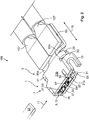
- the following is the basic structure of a flat contact socket 1 according to the invention for a 90 ° connection with reference to FIGS. 1 and 2 described.
- the flat contact socket 1 has a connecting portion 3 for electrical connection to an electrical conductor.
- a female body 7 With the connecting portion 3, a female body 7 is connected.
- the socket body 7 essentially serves for connection to a flat contact 63 (in FIG Fig. 2 indicated).
- the socket body 7 has for this purpose a flat contact receptacle 9.
- the flat contact receptacle 9 extends along a flat contact plane 11, which in Fig. 1 indicated by dashed lines.
- the flat contact receptacle 9 is open for insertion of a flat contact through an insertion opening 13.
- a blocking element 15 is arranged, which limits the penetration depth for a flat contact 63 in the flat contact receptacle 9.
- the insertion direction 17 extends parallel to the flat contact plane 11 from the insertion opening 13 in the direction of the blocking element 15. The insertion opening 13 and the blocking element 15 are thus opposite in the insertion direction 17.
- the flat contact socket 1 extends along a longitudinal direction 19 extending transversely to the insertion direction 17.
- the connecting section 3 and the socket body 7 are adjacent in the longitudinal direction 19.
- the connecting section 3 is designed such that an electrical conductor, in particular a cable, after the connection with the connecting section 3 also initially runs essentially parallel to the longitudinal direction 19 in the region directly adjacent to the flat contact socket 1.
- the flat contact socket 1 can also be shaped differently.
- the connecting portion 3 may be connected to the socket body 7 such that the connecting portion 3 extends parallel to the insertion direction 17 away from the latter.
- the connecting portion 3 can extend transversely to the insertion direction 17 and transversely to the longitudinal direction 19, in Fig. 1 that would be accordingly up or down.
- the socket body 7 has two transverse to the flat contact plane 11 opposite flat leg 21 a and 21 b.
- the socket body 7 has two transverse to the flat contact plane 11 opposite flat leg 21 a and 21 b.
- the legs 21 limit the flat contact receptacle 9 transversely to the flat contact plane 11.
- the legs 21 are formed substantially continuously. Alternatively, they may also have openings to save material, for example.
- the two legs 21 are connected by two webs 25 with each other.
- the flat contact socket 1 is preferably made as a stamped and bent part of an electrically conductive material 28. The production by punch bending allows a fast and cost-effective production of the flat contact socket. 1
- the blocking element 15 is connected to a cantilever 31 which extends away from the remaining bushing body 7 in the insertion direction 17. From the boom 31, the blocking element 15 projects transversely to the insertion direction 17 and transversely to the longitudinal direction 19, ie transversely to the flat contact plane 11 before.
- the blocking element 15 is spaced apart from the remaining flat contact receptacle 9 by the arrangement described above.
- the blocking element 15 is preferably produced in one piece with the socket body 7 and particularly preferably with the remaining flat contact socket 1. This can be achieved in particular in that the flat contact socket 1 is formed as a stamped and bent part.
- the blocking element 15 and the cantilever 31 can in this case be punched out of the material 28 of the flat contact bushing 1, which would form a continuous base in the region of the socket body 7 without an inventive blocking element 15. It can pass continuously into the leg 21 b and the free end, which forms the blocking element 15, be bent transversely to the insertion direction and transverse to the longitudinal direction 19.
- the locking element 15 has two struts 33, via which it is connected to the boom 31. Characterized the locking element 15 is formed like a bar and connected via two spaced struts 33 with the boom 31. Alternatively, the area between the struts 33 may also be closed. Preferably, however, material 28 is punched or removed there in order to reduce the necessary bending forces for producing the shape of the blocking element 15 or for bending up the material 28.
- the blocking element 15 extends over half the height 35 of the flat contact receptacle 9.
- the height 35 of the flat contact receptacle 9 is transverse to the flat contact plane 11 as the distance between the inner sides 37 of the two legs 21 measured.
- the flat contact socket 1 has two locking elements 41.
- the locking elements 41 are laterally of the flat contact receptacle 9 arranged. That is, they are arranged opposite each other in the longitudinal direction 19, wherein the flat contact receptacle 9 is arranged in the longitudinal direction 19 between them.
- the locking elements 41 limit the insertion opening 13 laterally or in the longitudinal direction 19.
- Each of the locking elements 41 extends from the leg 21 b to the opposite leg 21 a, and it may also be reversed in an alternative embodiment.
- Each of the locking elements 41 has a positive connection opening 43. This is preferably arranged at the free end 45 of the locking element 41.
- the locking element 41 is formed substantially strip-shaped and may be punched from material 28 of one of the two legs 21, in the described embodiment of the leg 21 b.
- the locking element 41 is bent in the direction of the opposite legs 21a, so that the positive connection opening 43 is arranged at the level of the leg 21a.
- This leg 21 a has a form-fitting projection 47, which is arranged in the connected state in the form-locking opening 43. In this way, a positive connection is formed transversely to the insertion direction 17. This prevents, on the one hand, the unintentional opening or compression of the two legs 21 from one another or one another as well as a displacement of the two legs 21 in the longitudinal direction 19.
- the legs 21 have contacting sections 55.
- the contacting sections 55 are used for electrical contacting of a flat contact arranged in the flat contact receptacle 9.
- the contacting portions 55 are arranged on the inner sides 37 of the legs 21. It is also possible that only one of the two legs 21 has a contacting section 55 for electrical contacting. Alternatively, for example, one of the legs 21 may also be provided with a pressure element, which is designed for the mechanical fixing of a flat contact in the flat contact receptacle 9.
- each contacting portion 55 has a plurality of projecting into the flat contact receptacle 9 and elastically to the respective leg 21 deflectable contact springs 57.
- each of the inner sides 37 in the contacting section 55 has a contacting plate 59, which is provided with a plurality of contact springs 57.
- the contacting plates 59 are electrically conductively connected to the respective legs 21.
- the contacting plates 59 are welded to the inner sides 37 of the legs 21.
- the two contacting plates 59 are opposite each other via the flat contact receptacle 9.
- the contacting plates 59 and the contacting portions 55 are spaced from the blocking element 15 against the insertion direction 17.
- the free space 61 which extends between themaschine istsabêten 55 and the blocking element 15, for example, for receiving a contact protection, which may be arranged around an electrically conductive part of a flat contact, serve.
- the connecting portion 3 is for connection by welding or soldering with at least one electrical conductor 107 (in Fig. 2 shown) is formed.
- the connecting section 3 has a connection surface 93.
- the connection surface 93 preferably extends parallel to the flat contact plane 11 and along the longitudinal direction 19 away from the flat contact receptacle 9 or the socket body 7.
- connection surface 93 is formed by two extensions 95.
- the extensions 95a and 95b extend away from the socket body 7 in the longitudinal direction 19 and abut one another transversely to the longitudinal direction 19 or in the insertion direction 17.
- the two extensions 95 may lie flush against each other or have a production-related gap between them.
- the two extensions 95 together form a straight and flat connection surface 93.
- the two extensions 95a and 95b extend from two spaced-apart regions 97a and 97b of the socket body 7.
- the region 97a is the end of the leg 21a which lies in the direction of the connection section 3
- the region 97b is the end of the leg which is in the direction of the connection section 3 21 b.
- Each of the extensions 95 thus extends away from one of the legs 21.
- the extension 95 a extends continuously from the leg 21 a parallel to the flat contact plane 11 and forms with the leg 21 a is a continuous and substantially flat surface.
- the extensions 95a and 95b may both initially in the direction of the respective opposite leg 21 b relationship meadow 21 a and then extend into the connecting portion 3.
- the height of the connecting surface 93 can then, viewed transversely to the flat contact plane 11, be arranged between the two opposing legs 21a and 21b.
- the extensions 95a and 95b may extend along a plane which lies centrally between the two legs 21a and 21b.
- the extension 95b is shaped starting from the leg 21b such that it first extends away from the socket body 7 in the direction of the leg 21a and then along the longitudinal direction 19. This allows both extensions 95 in the region of the connection surface 93 be arranged at a height.
- the term height here refers to a direction transverse to the insertion direction 17 and longitudinal direction 19 or parallel to the direction of the height 35 of the flat contact receptacle 9.
- the extension 95b has the offset region 99, in which the extension 95b is shaped so that it is arranged starting from the leg 21b at a height with the extension 95a.
- the offset region 99 is seen in the insertion direction 17 S-shaped.
- the extension 95b extends from the leg 21b initially in the longitudinal direction 19 away from the leg 21b and then extends at least partially in the direction of the leg 21a and the socket body 7. Subsequently, the extension 95b extends away from the socket body 7 in the longitudinal direction 19th As a result, a region 101 curved toward the socket body 7 is formed, whose convex side 103 points towards the socket body 7 and whose concave side 105 is open in the direction of the connection section 3. Through the concave side 105, a connecting surface 93 extended in the longitudinal direction 19 can be obtained.
- An electrical conductor 107 (can be welded to the connection surface 93 in the connection section 3, so that a connection is made to both extensions 95. A current flow through the flat contact socket 1 can then be split over both extensions 95 onto the two legs 21.
- each of the extensions 95a and 95b can also be welded to at least one electrical conductor. This is in Fig. 2 exemplified.
- the advantage of using at least two electrical conductors 107 is that both conductors 107 can each have a smaller line cross-section than would be the case with a single conductor. Since the two low-profile conductors are generally more flexible than a single conductor having a cross-section corresponding to the overall cross-section of the two individual conductors, smaller bending radii can be realized in laying the conductors 107.
- the flat contact socket 1 in conjunction with at least one electrical conductor 107 represents a connection arrangement 109 according to the invention.
Landscapes
- Coupling Device And Connection With Printed Circuit (AREA)
- Details Of Connecting Devices For Male And Female Coupling (AREA)
Priority Applications (3)
| Application Number | Priority Date | Filing Date | Title |
|---|---|---|---|
| JP2017205751A JP7051370B2 (ja) | 2016-10-28 | 2017-10-25 | フラットコンタクトソケット |
| US15/795,388 US10236612B2 (en) | 2016-10-28 | 2017-10-27 | Flat contact socket |
| CN201711035647.8A CN108011219B (zh) | 2016-10-28 | 2017-10-30 | 平坦触头插座 |
Applications Claiming Priority (1)
| Application Number | Priority Date | Filing Date | Title |
|---|---|---|---|
| DE102016221351.2A DE102016221351A1 (de) | 2016-10-28 | 2016-10-28 | Flachkontaktbuchse mit Ausleger |
Publications (2)
| Publication Number | Publication Date |
|---|---|
| EP3316402A1 true EP3316402A1 (fr) | 2018-05-02 |
| EP3316402B1 EP3316402B1 (fr) | 2020-04-08 |
Family
ID=57890656
Family Applications (2)
| Application Number | Title | Priority Date | Filing Date |
|---|---|---|---|
| EP17151499.5A Active EP3316402B1 (fr) | 2016-10-28 | 2017-01-13 | Douille de contact plate |
| EP17198732.4A Active EP3316403B1 (fr) | 2016-10-28 | 2017-10-27 | Douille de contact plat avec élément en porte-à-faux |
Family Applications After (1)
| Application Number | Title | Priority Date | Filing Date |
|---|---|---|---|
| EP17198732.4A Active EP3316403B1 (fr) | 2016-10-28 | 2017-10-27 | Douille de contact plat avec élément en porte-à-faux |
Country Status (5)
| Country | Link |
|---|---|
| US (2) | US10236612B2 (fr) |
| EP (2) | EP3316402B1 (fr) |
| JP (2) | JP7004542B2 (fr) |
| CN (2) | CN108011247B (fr) |
| DE (1) | DE102016221351A1 (fr) |
Families Citing this family (20)
| Publication number | Priority date | Publication date | Assignee | Title |
|---|---|---|---|---|
| JP6787175B2 (ja) * | 2017-02-22 | 2020-11-18 | 株式会社オートネットワーク技術研究所 | 多接点型端子 |
| KR102312421B1 (ko) * | 2018-06-22 | 2021-10-12 | 주식회사 엘지에너지솔루션 | 커넥터용 터미널 및 이를 포함하는 커넥터 |
| DE102018119844B4 (de) * | 2018-07-26 | 2022-10-06 | Auto-Kabel Management Gmbh | Elektrische Verbindung sowie Verfahren zur Herstellung einer elektrischen Verbindung |
| CN110265815A (zh) * | 2019-06-21 | 2019-09-20 | 陈丽霞 | 一种弯头连接器插孔 |
| US11515678B2 (en) | 2020-01-09 | 2022-11-29 | Aptiv Technologies Limited | Splice connector |
| US11387585B2 (en) * | 2020-08-05 | 2022-07-12 | Aptiv Technologies Limited | Anti-fretting/multiple contact terminal using knurl pattern |
| US11264735B1 (en) * | 2020-08-28 | 2022-03-01 | TE Connectivity Services Gmbh | Electrical terminal for terminating a wide size range of magnet wires |
| WO2022076233A1 (fr) * | 2020-10-08 | 2022-04-14 | Interplex Industries, Inc. | Connecteur de barre omnibus |
| CN112038805A (zh) * | 2020-10-13 | 2020-12-04 | 陈丽霞 | 一种弯直头连接器插孔 |
| JP7444043B2 (ja) * | 2020-12-16 | 2024-03-06 | 株式会社オートネットワーク技術研究所 | 端子ユニット |
| CN112751228A (zh) * | 2020-12-30 | 2021-05-04 | 泰科电子(上海)有限公司 | 用于高压连接的端子本体、线缆组件及连接器 |
| CN214797803U (zh) | 2020-12-30 | 2021-11-19 | 泰科电子(上海)有限公司 | 端子本体、连接端子及用于制作端子本体的片料 |
| CN115224514A (zh) * | 2021-04-14 | 2022-10-21 | 泰科电子(上海)有限公司 | 电连接端子和电连接组件 |
| US11646510B2 (en) | 2021-04-29 | 2023-05-09 | Aptiv Technologies Limited | Shielding electrical terminal with knurling on inner contact walls |
| CN113258352B (zh) | 2021-05-26 | 2022-11-29 | 宣城立讯精密工业有限公司 | 电性连接套件及电连接器 |
| CN113258372B (zh) | 2021-05-26 | 2022-12-02 | 宣城立讯精密工业有限公司 | 电性连接套件及电性连接器 |
| JP7608288B2 (ja) * | 2021-07-29 | 2025-01-06 | 古河電気工業株式会社 | メス型端子、コネクタ、端子付き電線、コネクタ付き電線及びワイヤーハーネス |
| JP7740927B2 (ja) * | 2021-07-29 | 2025-09-17 | 古河電気工業株式会社 | メス型端子、コネクタ、端子付き電線、コネクタ付き電線及びワイヤーハーネス |
| JP2024032406A (ja) * | 2022-08-29 | 2024-03-12 | 古河電気工業株式会社 | 接続端子、コネクタ、端子付き電線及びワイヤーハーネス |
| EP4407808A1 (fr) * | 2023-01-24 | 2024-07-31 | Tyco Electronics France SAS | Prise, connecteur de prise, élément de contact et ensemble de connexion |
Citations (3)
| Publication number | Priority date | Publication date | Assignee | Title |
|---|---|---|---|---|
| US20120129407A1 (en) * | 2010-11-24 | 2012-05-24 | Lear Corporation | Power terminal |
| DE102014001692A1 (de) * | 2013-02-08 | 2014-08-14 | Lear Corporation | Buchsen-elektroanschlussteil mit spalt zwischen anschlussteilstiften |
| CN104037523B (zh) * | 2014-06-13 | 2016-05-11 | 四川永贵科技有限公司 | 一种大电流端子 |
Family Cites Families (95)
| Publication number | Priority date | Publication date | Assignee | Title |
|---|---|---|---|---|
| NL124818C (fr) * | 1960-05-26 | |||
| GB1463751A (en) * | 1974-05-03 | 1977-02-09 | Amp Inc | Electrical tab receptacle |
| FR2478383A1 (fr) * | 1980-03-11 | 1981-09-18 | Amp France | Organe de contact electrique destine a s'accoupler avec un organe de contact male, et connecteur electrique comportant un tel organe de contact |
| US4679887A (en) * | 1982-03-24 | 1987-07-14 | Amp Incorporated | Electrical terminal |
| US4421375A (en) * | 1982-03-29 | 1983-12-20 | Amp Incorporated | Flag-type terminal having insulation displacement wire connection |
| NL8202668A (nl) * | 1982-07-02 | 1984-02-01 | Philips Nv | Elektrisch kontaktorgaan. |
| US4534613A (en) * | 1983-10-31 | 1985-08-13 | Amp Incorporated | Receptacle terminal having locking lance |
| FR2559624B1 (fr) * | 1984-02-14 | 1986-05-23 | Labinal | Organe de contact electrique |
| FR2589637B1 (fr) * | 1985-11-05 | 1987-12-11 | Labinal | Element femelle de contacts electriques |
| US4685754A (en) * | 1985-12-13 | 1987-08-11 | Amp Incorporated | Electrical tab receptacle |
| GB8700870D0 (en) * | 1987-01-15 | 1987-02-18 | Amp Italia | Electrical tabreceptacle |
| FR2693041B1 (fr) * | 1992-06-26 | 1996-04-05 | Proner Comatel Sa | Dispositif de connexion electrique par clip et languette. |
| US5525070A (en) * | 1994-04-15 | 1996-06-11 | Panduit Corp. | Positive lock insulated disconnect |
| DE9416056U1 (de) * | 1994-10-06 | 1994-11-24 | Stocko Metallwarenfabriken Henkels Und Sohn Gmbh & Co, 42327 Wuppertal | Verriegelbare Flachsteckhülse für eine elektrische Verbindung |
| US5588884A (en) * | 1995-09-08 | 1996-12-31 | Packard Hughes Interconnect Company | Stamped and formed contacts for a power connector |
| US5800220A (en) * | 1995-10-23 | 1998-09-01 | Framatome Connectors Interlock Inc. | Tab receptacle terminal |
| US6039615A (en) * | 1996-03-15 | 2000-03-21 | The Whitaker Corporation | Female electrical terminal having overstress members |
| US5911605A (en) * | 1997-10-16 | 1999-06-15 | Ui Automotive Dearborn, Inc. | Universal terminal connection |
| JP2000173703A (ja) * | 1998-12-08 | 2000-06-23 | Yazaki Corp | 電気コンタクト |
| US6416340B2 (en) * | 2000-05-04 | 2002-07-09 | Christopher E. Schaefer | Single blade terminal power connector system |
| GB0016790D0 (en) * | 2000-07-07 | 2000-08-30 | Tyco Electronics Amp Es Sa | Electrical connector |
| US6276960B1 (en) * | 2000-08-29 | 2001-08-21 | Delphi Technologies, Inc. | Electrical power connector system |
| US6485337B2 (en) * | 2000-08-30 | 2002-11-26 | Delphi Technologies, Inc. | Electrical connector |
| US6287156B1 (en) * | 2000-08-31 | 2001-09-11 | Lear Corporation | Electrical terminal connector |
| US6672911B2 (en) * | 2000-09-15 | 2004-01-06 | Alcoa Fujikura Limited | Electrical terminal socket assembly including 90 angled and sealed connectors |
| FR2817401B1 (fr) * | 2000-11-30 | 2003-01-10 | Proner Comatel Sa | Element femelle de connexion electrique |
| US20030060090A1 (en) * | 2001-09-21 | 2003-03-27 | Allgood Christopher L. | High current automotive electrical connector and terminal |
| US6692316B2 (en) * | 2002-04-16 | 2004-02-17 | Delphi Technologies, Inc. | High current terminal blade type sealed connection system |
| DE10351540B3 (de) * | 2003-11-03 | 2005-08-11 | Intedis Gmbh & Co. Kg | Flachsteckbuchse |
| DE102004015345A1 (de) * | 2004-03-30 | 2005-10-27 | Kostal Kontakt Systeme Gmbh | Elektrischer Steckhülsenkontakt für Hochstromanwendungen |
| DE102005017988B3 (de) * | 2005-04-19 | 2006-11-16 | Tyco Electronics Amp Gmbh | Elektrische Kontakthülse |
| JP4607749B2 (ja) * | 2005-12-06 | 2011-01-05 | トヨタ自動車株式会社 | 雌型コネクタ端子及び雌型コネクタ |
| DE102006009074B4 (de) * | 2006-02-28 | 2016-02-25 | Robert Bosch Gmbh | Elektrischer Steckverbinder mit vorgespannter Kontaktlamelle |
| JP2008140589A (ja) * | 2006-11-30 | 2008-06-19 | Yazaki Corp | 雌型端子 |
| DE202007000302U1 (de) | 2007-01-09 | 2007-05-16 | Sorig, Ludger | Elektrischer Steckbuchsenkontakt für Hochstromanwendungen |
| DE102007016070A1 (de) * | 2007-04-03 | 2008-10-09 | Lear Corp., Southfield | Elektrische Anschlussanordnung und Verfahren zum Nutzen der elektrischen Anschlussanordnung |
| JP4488372B2 (ja) | 2007-08-03 | 2010-06-23 | ヒロセ電機株式会社 | ケーブル用電気コネクタ |
| CN101816103B (zh) * | 2007-10-02 | 2013-06-19 | 奥斯兰姆有限公司 | 插塞装置、插塞连接器以及制造插塞装置的方法 |
| KR101006881B1 (ko) * | 2007-12-14 | 2011-01-12 | 주식회사 엘지화학 | 개선된 체결식 구조의 pcm 및 이를 포함하고 있는전지팩 |
| DE102008017043B3 (de) * | 2008-04-03 | 2009-09-03 | Lear Corp., Southfield | Verfahren zur Herstellung eines Buchsenanschlussstückes |
| US20100029146A1 (en) * | 2008-08-04 | 2010-02-04 | Tyco Electronics Corporation | Socket contact |
| JP5185022B2 (ja) * | 2008-08-27 | 2013-04-17 | イリソ電子工業株式会社 | 電気接触子及びこれを用いたコネクタ |
| US7766706B2 (en) * | 2008-11-17 | 2010-08-03 | J. S. T. Corporation | Female terminal assembly with compression clip |
| EP2211425A1 (fr) * | 2009-01-23 | 2010-07-28 | MTA S.p.A. | Terminal électrique femelle |
| JP5643753B2 (ja) * | 2009-05-20 | 2014-12-17 | 行田電線株式会社 | 接続端子、端子接続構造、及び端子ボックス |
| US7892050B2 (en) * | 2009-06-17 | 2011-02-22 | Lear Corporation | High power fuse terminal with scalability |
| US8366497B2 (en) * | 2009-06-17 | 2013-02-05 | Lear Corporation | Power terminal |
| US8668531B2 (en) * | 2009-07-03 | 2014-03-11 | Yazaki Corporation | Terminal |
| JP5381492B2 (ja) * | 2009-08-19 | 2014-01-08 | 住友電装株式会社 | 雌端子金具 |
| KR101598633B1 (ko) * | 2009-11-11 | 2016-02-29 | 타이코에이엠피 주식회사 | 커넥터용 단자 |
| DE102010002176B4 (de) * | 2010-02-22 | 2011-12-15 | Tyco Electronics Amp Gmbh | Kontakteinrichtung |
| JP5447971B2 (ja) * | 2010-04-08 | 2014-03-19 | 住友電装株式会社 | 端子金具の接続構造 |
| US8057261B1 (en) * | 2010-11-02 | 2011-11-15 | Etco, Inc. | Flag terminal insulator |
| US8419486B2 (en) * | 2010-12-17 | 2013-04-16 | Tyco Electronics Corporation | Receptacle terminal with a contact spring |
| DE202011003555U1 (de) * | 2011-03-04 | 2011-05-26 | ROSENBERGER Hochfrequenztechnik GmbH & Co. KG, 83413 | Hochstromsteckverbinder mit Ringfederkontaktierung |
| JP5083847B1 (ja) * | 2011-06-07 | 2012-11-28 | 日本航空電子工業株式会社 | コンタクトエレメント及びコネクタ |
| JP5723695B2 (ja) * | 2011-06-21 | 2015-05-27 | 矢崎総業株式会社 | 雌端子 |
| KR101342507B1 (ko) * | 2011-09-02 | 2013-12-17 | 삼성에스디아이 주식회사 | 이차전지 팩 |
| JP6055173B2 (ja) * | 2011-09-27 | 2016-12-27 | 矢崎総業株式会社 | 雌端子 |
| DE102011085700A1 (de) * | 2011-11-03 | 2013-05-08 | Bayerische Motoren Werke Aktiengesellschaft | Hochstrom-Steckverbinder für Kraftfahrzeuganwendungen |
| JP5872970B2 (ja) * | 2012-06-13 | 2016-03-01 | 矢崎総業株式会社 | コネクタ端子及びこのコネクタ端子と相手端子との接続構造 |
| DE102013013633A1 (de) * | 2012-09-24 | 2014-04-10 | Lear Corp. | Elektrischer Anschluss |
| US8998655B2 (en) * | 2012-09-24 | 2015-04-07 | Lear Corporation | Electrical terminal |
| US9065192B2 (en) * | 2013-09-19 | 2015-06-23 | Tyco Electronics Corporation | Power terminal connector |
| US9166322B2 (en) * | 2013-02-08 | 2015-10-20 | Lear Corporation | Female electric terminal with gap between terminal beams |
| US9379470B2 (en) * | 2013-02-18 | 2016-06-28 | Lear Corporation | Female electrical connector with terminal arm extension protection |
| US9548553B2 (en) * | 2013-03-15 | 2017-01-17 | Lear Corporation | Terminal with front end protection |
| US9153889B2 (en) * | 2013-04-09 | 2015-10-06 | Delphi Technologies, Inc. | Electrical connector system connectable in a straight or right angle configuration |
| US8992258B2 (en) * | 2013-04-26 | 2015-03-31 | Delphi Technologies, Inc. | Electrical cable connector shield with positive retention locking feature |
| JP6389598B2 (ja) * | 2013-07-05 | 2018-09-12 | 矢崎総業株式会社 | メス端子アセンブリ |
| US9190756B2 (en) * | 2013-08-01 | 2015-11-17 | Lear Corporation | Electrical terminal assembly |
| WO2015037808A1 (fr) * | 2013-09-12 | 2015-03-19 | 조인셋 주식회사 | Connecteur électrique soudable |
| DE102014113490A1 (de) * | 2013-09-18 | 2015-03-19 | Hirschmann Automotive Gmbh | Kontaktelement für einen Steckverbinder |
| CN203456624U (zh) * | 2013-09-27 | 2014-02-26 | 泰科电子(上海)有限公司 | 连接端子 |
| JP2015076199A (ja) * | 2013-10-07 | 2015-04-20 | 矢崎総業株式会社 | 雌端子金具 |
| JP6369029B2 (ja) * | 2014-01-28 | 2018-08-08 | オムロン株式会社 | コネクタ |
| TWI513129B (zh) * | 2014-03-07 | 2015-12-11 | Japan Aviation Electron | 連接器組合體 |
| DE102014005536B4 (de) * | 2014-04-16 | 2016-04-07 | Lisa Dräxlmaier GmbH | Kontaktlamelle zur Bildung einer Steckbuchse durch Koppeln mit einem Gehäuseelement sowie Steckbuchse, gebildet durch Koppeln der Kontaktlamelle mit einem Gehäuselement |
| JP6014075B2 (ja) * | 2014-04-17 | 2016-10-25 | ヒロセ電機株式会社 | 電気コネクタ組立体 |
| JP5747102B1 (ja) * | 2014-04-18 | 2015-07-08 | 日本航空電子工業株式会社 | 雌型コンタクト及び電源用コネクタ |
| JP6591146B2 (ja) * | 2014-07-08 | 2019-10-16 | 日本航空電子工業株式会社 | コンタクト及びそれを備えるコネクタ |
| EP3051635B1 (fr) * | 2015-01-30 | 2018-01-17 | TE Connectivity Germany GmbH | Moyens de contact électrique et ensemble de câble électrique pour l'industrie automobile |
| DE102015201694A1 (de) * | 2015-01-30 | 2016-08-04 | Te Connectivity Germany Gmbh | Elektrische Kontaktvorrichtung |
| DE102015104377B4 (de) * | 2015-03-24 | 2020-04-02 | Lisa Dräxlmaier GmbH | Kontaktteil und Verfahren zum Herstellen eines Kontaktteils |
| CN105098395B (zh) * | 2015-07-16 | 2017-12-12 | 凡甲电子(苏州)有限公司 | 电连接器及其端子组件 |
| DE102015216632A1 (de) * | 2015-08-31 | 2017-03-02 | Te Connectivity Germany Gmbh | Anordnung zum Herstellen einer elektrischen Verbindung zwischen einem Flachkontakt und einem Hochstromleiter |
| DE102015119723A1 (de) * | 2015-11-16 | 2017-05-18 | Te Connectivity Germany Gmbh | Kontakteinrichtungs-Arretierfeder, elektrische Kontakteinrichtungs-Baugruppe sowie elektrischer Verbinder |
| US9537245B1 (en) * | 2015-11-18 | 2017-01-03 | Eaton Corporation | Meter center, and socket assembly and method of assembling a socket assembly therefor |
| DE102016201103B4 (de) * | 2016-01-26 | 2023-10-05 | Lisa Dräxlmaier GmbH | Kontaktteil |
| CN107134674B (zh) * | 2016-02-29 | 2021-04-27 | 泰科电子(上海)有限公司 | 导电连接件及连接组件 |
| JP6619287B2 (ja) * | 2016-04-14 | 2019-12-11 | 日本航空電子工業株式会社 | コネクタ端子 |
| JP6591341B2 (ja) * | 2016-04-21 | 2019-10-16 | 日本航空電子工業株式会社 | コネクタ端子 |
| DE102016209478A1 (de) * | 2016-05-31 | 2017-11-30 | Te Connectivity Germany Gmbh | Verbindungskäfig zur Verbindung zweier elektrischer Flachkontakte |
| US10784595B2 (en) * | 2016-08-01 | 2020-09-22 | Te Connectivity Corporation | Power terminal for an electrical connector |
| US9692163B1 (en) * | 2016-08-30 | 2017-06-27 | Te Connectivity Corporation | Crush rib housing for postive lock receptacle |
-
2016
- 2016-10-28 DE DE102016221351.2A patent/DE102016221351A1/de not_active Ceased
-
2017
- 2017-01-13 EP EP17151499.5A patent/EP3316402B1/fr active Active
- 2017-10-25 JP JP2017205727A patent/JP7004542B2/ja active Active
- 2017-10-25 JP JP2017205751A patent/JP7051370B2/ja active Active
- 2017-10-27 US US15/795,388 patent/US10236612B2/en active Active
- 2017-10-27 US US15/795,461 patent/US10256560B2/en active Active
- 2017-10-27 EP EP17198732.4A patent/EP3316403B1/fr active Active
- 2017-10-30 CN CN201711035648.2A patent/CN108011247B/zh active Active
- 2017-10-30 CN CN201711035647.8A patent/CN108011219B/zh active Active
Patent Citations (3)
| Publication number | Priority date | Publication date | Assignee | Title |
|---|---|---|---|---|
| US20120129407A1 (en) * | 2010-11-24 | 2012-05-24 | Lear Corporation | Power terminal |
| DE102014001692A1 (de) * | 2013-02-08 | 2014-08-14 | Lear Corporation | Buchsen-elektroanschlussteil mit spalt zwischen anschlussteilstiften |
| CN104037523B (zh) * | 2014-06-13 | 2016-05-11 | 四川永贵科技有限公司 | 一种大电流端子 |
Also Published As
| Publication number | Publication date |
|---|---|
| US10236612B2 (en) | 2019-03-19 |
| DE102016221351A1 (de) | 2018-05-03 |
| EP3316403A1 (fr) | 2018-05-02 |
| JP2018073826A (ja) | 2018-05-10 |
| JP7004542B2 (ja) | 2022-01-21 |
| EP3316402B1 (fr) | 2020-04-08 |
| US20180123276A1 (en) | 2018-05-03 |
| CN108011247A (zh) | 2018-05-08 |
| US20180123275A1 (en) | 2018-05-03 |
| CN108011219A (zh) | 2018-05-08 |
| US10256560B2 (en) | 2019-04-09 |
| EP3316403B1 (fr) | 2019-11-20 |
| JP2018073827A (ja) | 2018-05-10 |
| CN108011219B (zh) | 2021-06-25 |
| CN108011247B (zh) | 2021-03-30 |
| JP7051370B2 (ja) | 2022-04-11 |
Similar Documents
| Publication | Publication Date | Title |
|---|---|---|
| EP3316402B1 (fr) | Douille de contact plate | |
| DE102013223570B4 (de) | Stiftkontakt mit einem als Stanzbiegeteil gefertigten Kontaktkörper und einem massiven Kontaktstift | |
| EP3734768B1 (fr) | Connecteur enfichable d'un raccord enfichable électrique ainsi que raccord enfichable électrique ainsi formé | |
| EP3507866B1 (fr) | Borne de raccordement d'un conducteur | |
| EP2966731B1 (fr) | Élément de contact et utilisation d'un tel élément de contact dans un connecteur à fiches | |
| EP2086064B1 (fr) | Contact d'estampage électrique | |
| DE1440806C (fr) | ||
| EP3293833B1 (fr) | Connecteur de rails d'alimentation | |
| DE2224326A1 (de) | Elektrische Verbinderanordnung | |
| EP3353859A1 (fr) | Dispositif de connexion pour conducteur | |
| DE102010045470A1 (de) | Steckereinheit | |
| DE102009030645B4 (de) | Brückerelement und Set aus zumindest einem Klemmelement und Brückerelement | |
| DE2547166A1 (de) | Elektrische verbinderanordnung | |
| DE4016114C2 (de) | Elektrischer Mehrkontakt-Verbinder, der eine geringe Verbindungs- und Trennkraft erfordert | |
| EP3577723B1 (fr) | Lame de contact pour élément de connecteur de type femelle et élément de connecteur de type femelle | |
| DE2024365A1 (de) | Elektrische Verbinderanordnung | |
| DE102007048710B4 (de) | Elektrischer Querverbinder | |
| EP2741371B1 (fr) | Connecteur à fiches et dispositif doté d'un tel connecteur à fiches | |
| EP3069416B1 (fr) | Barrette de raccordement et adaptateurs de borne à ressort | |
| EP0865105A1 (fr) | Douille de connexion électrique avec ressort de contact et douille utilisable comme contact terminal | |
| DE102022112197A1 (de) | Modulares Lichtband mit Vorzentrierungseinrichtung | |
| DE10244946A1 (de) | Kontaktbuchse für eine elektrische Steckverbindung | |
| DE2448349C2 (de) | Verbinderanordnung mit einem mit einer gedruckten Schaltungsplatte verbundenen Verbinder | |
| DE60006734T2 (de) | Unterbrecher | |
| DE102016000384B4 (de) | Mehrpoliger elektrischer Verbinder |
Legal Events
| Date | Code | Title | Description |
|---|---|---|---|
| PUAI | Public reference made under article 153(3) epc to a published international application that has entered the european phase |
Free format text: ORIGINAL CODE: 0009012 |
|
| STAA | Information on the status of an ep patent application or granted ep patent |
Free format text: STATUS: THE APPLICATION HAS BEEN PUBLISHED |
|
| AK | Designated contracting states |
Kind code of ref document: A1 Designated state(s): AL AT BE BG CH CY CZ DE DK EE ES FI FR GB GR HR HU IE IS IT LI LT LU LV MC MK MT NL NO PL PT RO RS SE SI SK SM TR |
|
| AX | Request for extension of the european patent |
Extension state: BA ME |
|
| STAA | Information on the status of an ep patent application or granted ep patent |
Free format text: STATUS: REQUEST FOR EXAMINATION WAS MADE |
|
| 17P | Request for examination filed |
Effective date: 20181102 |
|
| RBV | Designated contracting states (corrected) |
Designated state(s): AL AT BE BG CH CY CZ DE DK EE ES FI FR GB GR HR HU IE IS IT LI LT LU LV MC MK MT NL NO PL PT RO RS SE SI SK SM TR |
|
| RIC1 | Information provided on ipc code assigned before grant |
Ipc: H01R 11/11 20060101AFI20190905BHEP Ipc: H01R 13/11 20060101ALI20190905BHEP Ipc: H01R 4/48 20060101ALN20190905BHEP Ipc: H01R 12/70 20110101ALI20190905BHEP Ipc: H01R 43/16 20060101ALN20190905BHEP Ipc: H01R 4/02 20060101ALN20190905BHEP Ipc: H01R 12/51 20110101ALI20190905BHEP |
|
| RIC1 | Information provided on ipc code assigned before grant |
Ipc: H01R 13/11 20060101ALI20191004BHEP Ipc: H01R 43/16 20060101ALN20191004BHEP Ipc: H01R 4/48 20060101ALN20191004BHEP Ipc: H01R 4/02 20060101ALN20191004BHEP Ipc: H01R 12/51 20110101ALI20191004BHEP Ipc: H01R 12/70 20110101ALI20191004BHEP Ipc: H01R 11/11 20060101AFI20191004BHEP |
|
| GRAP | Despatch of communication of intention to grant a patent |
Free format text: ORIGINAL CODE: EPIDOSNIGR1 |
|
| STAA | Information on the status of an ep patent application or granted ep patent |
Free format text: STATUS: GRANT OF PATENT IS INTENDED |
|
| INTG | Intention to grant announced |
Effective date: 20191120 |
|
| GRAS | Grant fee paid |
Free format text: ORIGINAL CODE: EPIDOSNIGR3 |
|
| GRAA | (expected) grant |
Free format text: ORIGINAL CODE: 0009210 |
|
| STAA | Information on the status of an ep patent application or granted ep patent |
Free format text: STATUS: THE PATENT HAS BEEN GRANTED |
|
| AK | Designated contracting states |
Kind code of ref document: B1 Designated state(s): AL AT BE BG CH CY CZ DE DK EE ES FI FR GB GR HR HU IE IS IT LI LT LU LV MC MK MT NL NO PL PT RO RS SE SI SK SM TR |
|
| REG | Reference to a national code |
Ref country code: AT Ref legal event code: REF Ref document number: 1255609 Country of ref document: AT Kind code of ref document: T Effective date: 20200415 Ref country code: CH Ref legal event code: EP |
|
| REG | Reference to a national code |
Ref country code: DE Ref legal event code: R096 Ref document number: 502017004579 Country of ref document: DE |
|
| REG | Reference to a national code |
Ref country code: IE Ref legal event code: FG4D Free format text: LANGUAGE OF EP DOCUMENT: GERMAN |
|
| REG | Reference to a national code |
Ref country code: NL Ref legal event code: MP Effective date: 20200408 |
|
| REG | Reference to a national code |
Ref country code: LT Ref legal event code: MG4D |
|
| PG25 | Lapsed in a contracting state [announced via postgrant information from national office to epo] |
Ref country code: SE Free format text: LAPSE BECAUSE OF FAILURE TO SUBMIT A TRANSLATION OF THE DESCRIPTION OR TO PAY THE FEE WITHIN THE PRESCRIBED TIME-LIMIT Effective date: 20200408 Ref country code: NO Free format text: LAPSE BECAUSE OF FAILURE TO SUBMIT A TRANSLATION OF THE DESCRIPTION OR TO PAY THE FEE WITHIN THE PRESCRIBED TIME-LIMIT Effective date: 20200708 Ref country code: IS Free format text: LAPSE BECAUSE OF FAILURE TO SUBMIT A TRANSLATION OF THE DESCRIPTION OR TO PAY THE FEE WITHIN THE PRESCRIBED TIME-LIMIT Effective date: 20200808 Ref country code: PT Free format text: LAPSE BECAUSE OF FAILURE TO SUBMIT A TRANSLATION OF THE DESCRIPTION OR TO PAY THE FEE WITHIN THE PRESCRIBED TIME-LIMIT Effective date: 20200817 Ref country code: LT Free format text: LAPSE BECAUSE OF FAILURE TO SUBMIT A TRANSLATION OF THE DESCRIPTION OR TO PAY THE FEE WITHIN THE PRESCRIBED TIME-LIMIT Effective date: 20200408 Ref country code: FI Free format text: LAPSE BECAUSE OF FAILURE TO SUBMIT A TRANSLATION OF THE DESCRIPTION OR TO PAY THE FEE WITHIN THE PRESCRIBED TIME-LIMIT Effective date: 20200408 Ref country code: GR Free format text: LAPSE BECAUSE OF FAILURE TO SUBMIT A TRANSLATION OF THE DESCRIPTION OR TO PAY THE FEE WITHIN THE PRESCRIBED TIME-LIMIT Effective date: 20200709 Ref country code: NL Free format text: LAPSE BECAUSE OF FAILURE TO SUBMIT A TRANSLATION OF THE DESCRIPTION OR TO PAY THE FEE WITHIN THE PRESCRIBED TIME-LIMIT Effective date: 20200408 |
|
| PG25 | Lapsed in a contracting state [announced via postgrant information from national office to epo] |
Ref country code: LV Free format text: LAPSE BECAUSE OF FAILURE TO SUBMIT A TRANSLATION OF THE DESCRIPTION OR TO PAY THE FEE WITHIN THE PRESCRIBED TIME-LIMIT Effective date: 20200408 Ref country code: BG Free format text: LAPSE BECAUSE OF FAILURE TO SUBMIT A TRANSLATION OF THE DESCRIPTION OR TO PAY THE FEE WITHIN THE PRESCRIBED TIME-LIMIT Effective date: 20200708 Ref country code: RS Free format text: LAPSE BECAUSE OF FAILURE TO SUBMIT A TRANSLATION OF THE DESCRIPTION OR TO PAY THE FEE WITHIN THE PRESCRIBED TIME-LIMIT Effective date: 20200408 Ref country code: HR Free format text: LAPSE BECAUSE OF FAILURE TO SUBMIT A TRANSLATION OF THE DESCRIPTION OR TO PAY THE FEE WITHIN THE PRESCRIBED TIME-LIMIT Effective date: 20200408 |
|
| PG25 | Lapsed in a contracting state [announced via postgrant information from national office to epo] |
Ref country code: AL Free format text: LAPSE BECAUSE OF FAILURE TO SUBMIT A TRANSLATION OF THE DESCRIPTION OR TO PAY THE FEE WITHIN THE PRESCRIBED TIME-LIMIT Effective date: 20200408 |
|
| REG | Reference to a national code |
Ref country code: DE Ref legal event code: R097 Ref document number: 502017004579 Country of ref document: DE |
|
| PG25 | Lapsed in a contracting state [announced via postgrant information from national office to epo] |
Ref country code: DK Free format text: LAPSE BECAUSE OF FAILURE TO SUBMIT A TRANSLATION OF THE DESCRIPTION OR TO PAY THE FEE WITHIN THE PRESCRIBED TIME-LIMIT Effective date: 20200408 Ref country code: ES Free format text: LAPSE BECAUSE OF FAILURE TO SUBMIT A TRANSLATION OF THE DESCRIPTION OR TO PAY THE FEE WITHIN THE PRESCRIBED TIME-LIMIT Effective date: 20200408 Ref country code: RO Free format text: LAPSE BECAUSE OF FAILURE TO SUBMIT A TRANSLATION OF THE DESCRIPTION OR TO PAY THE FEE WITHIN THE PRESCRIBED TIME-LIMIT Effective date: 20200408 Ref country code: CZ Free format text: LAPSE BECAUSE OF FAILURE TO SUBMIT A TRANSLATION OF THE DESCRIPTION OR TO PAY THE FEE WITHIN THE PRESCRIBED TIME-LIMIT Effective date: 20200408 Ref country code: SM Free format text: LAPSE BECAUSE OF FAILURE TO SUBMIT A TRANSLATION OF THE DESCRIPTION OR TO PAY THE FEE WITHIN THE PRESCRIBED TIME-LIMIT Effective date: 20200408 Ref country code: EE Free format text: LAPSE BECAUSE OF FAILURE TO SUBMIT A TRANSLATION OF THE DESCRIPTION OR TO PAY THE FEE WITHIN THE PRESCRIBED TIME-LIMIT Effective date: 20200408 |
|
| PLBE | No opposition filed within time limit |
Free format text: ORIGINAL CODE: 0009261 |
|
| STAA | Information on the status of an ep patent application or granted ep patent |
Free format text: STATUS: NO OPPOSITION FILED WITHIN TIME LIMIT |
|
| PG25 | Lapsed in a contracting state [announced via postgrant information from national office to epo] |
Ref country code: SK Free format text: LAPSE BECAUSE OF FAILURE TO SUBMIT A TRANSLATION OF THE DESCRIPTION OR TO PAY THE FEE WITHIN THE PRESCRIBED TIME-LIMIT Effective date: 20200408 Ref country code: PL Free format text: LAPSE BECAUSE OF FAILURE TO SUBMIT A TRANSLATION OF THE DESCRIPTION OR TO PAY THE FEE WITHIN THE PRESCRIBED TIME-LIMIT Effective date: 20200408 |
|
| 26N | No opposition filed |
Effective date: 20210112 |
|
| PG25 | Lapsed in a contracting state [announced via postgrant information from national office to epo] |
Ref country code: SI Free format text: LAPSE BECAUSE OF FAILURE TO SUBMIT A TRANSLATION OF THE DESCRIPTION OR TO PAY THE FEE WITHIN THE PRESCRIBED TIME-LIMIT Effective date: 20200408 |
|
| PG25 | Lapsed in a contracting state [announced via postgrant information from national office to epo] |
Ref country code: MC Free format text: LAPSE BECAUSE OF FAILURE TO SUBMIT A TRANSLATION OF THE DESCRIPTION OR TO PAY THE FEE WITHIN THE PRESCRIBED TIME-LIMIT Effective date: 20200408 |
|
| REG | Reference to a national code |
Ref country code: CH Ref legal event code: PL |
|
| GBPC | Gb: european patent ceased through non-payment of renewal fee |
Effective date: 20210113 |
|
| PG25 | Lapsed in a contracting state [announced via postgrant information from national office to epo] |
Ref country code: LU Free format text: LAPSE BECAUSE OF NON-PAYMENT OF DUE FEES Effective date: 20210113 |
|
| REG | Reference to a national code |
Ref country code: BE Ref legal event code: MM Effective date: 20210131 |
|
| PG25 | Lapsed in a contracting state [announced via postgrant information from national office to epo] |
Ref country code: LI Free format text: LAPSE BECAUSE OF NON-PAYMENT OF DUE FEES Effective date: 20210131 Ref country code: GB Free format text: LAPSE BECAUSE OF NON-PAYMENT OF DUE FEES Effective date: 20210113 Ref country code: CH Free format text: LAPSE BECAUSE OF NON-PAYMENT OF DUE FEES Effective date: 20210131 |
|
| PG25 | Lapsed in a contracting state [announced via postgrant information from national office to epo] |
Ref country code: IE Free format text: LAPSE BECAUSE OF NON-PAYMENT OF DUE FEES Effective date: 20210113 |
|
| PG25 | Lapsed in a contracting state [announced via postgrant information from national office to epo] |
Ref country code: BE Free format text: LAPSE BECAUSE OF NON-PAYMENT OF DUE FEES Effective date: 20210131 |
|
| REG | Reference to a national code |
Ref country code: AT Ref legal event code: MM01 Ref document number: 1255609 Country of ref document: AT Kind code of ref document: T Effective date: 20220113 |
|
| PG25 | Lapsed in a contracting state [announced via postgrant information from national office to epo] |
Ref country code: AT Free format text: LAPSE BECAUSE OF NON-PAYMENT OF DUE FEES Effective date: 20220113 |
|
| PG25 | Lapsed in a contracting state [announced via postgrant information from national office to epo] |
Ref country code: CY Free format text: LAPSE BECAUSE OF FAILURE TO SUBMIT A TRANSLATION OF THE DESCRIPTION OR TO PAY THE FEE WITHIN THE PRESCRIBED TIME-LIMIT Effective date: 20200408 |
|
| PG25 | Lapsed in a contracting state [announced via postgrant information from national office to epo] |
Ref country code: HU Free format text: LAPSE BECAUSE OF FAILURE TO SUBMIT A TRANSLATION OF THE DESCRIPTION OR TO PAY THE FEE WITHIN THE PRESCRIBED TIME-LIMIT; INVALID AB INITIO Effective date: 20170113 |
|
| PG25 | Lapsed in a contracting state [announced via postgrant information from national office to epo] |
Ref country code: MK Free format text: LAPSE BECAUSE OF FAILURE TO SUBMIT A TRANSLATION OF THE DESCRIPTION OR TO PAY THE FEE WITHIN THE PRESCRIBED TIME-LIMIT Effective date: 20200408 |
|
| PG25 | Lapsed in a contracting state [announced via postgrant information from national office to epo] |
Ref country code: TR Free format text: LAPSE BECAUSE OF FAILURE TO SUBMIT A TRANSLATION OF THE DESCRIPTION OR TO PAY THE FEE WITHIN THE PRESCRIBED TIME-LIMIT Effective date: 20200408 |
|
| PG25 | Lapsed in a contracting state [announced via postgrant information from national office to epo] |
Ref country code: MT Free format text: LAPSE BECAUSE OF FAILURE TO SUBMIT A TRANSLATION OF THE DESCRIPTION OR TO PAY THE FEE WITHIN THE PRESCRIBED TIME-LIMIT Effective date: 20200408 |
|
| PGFP | Annual fee paid to national office [announced via postgrant information from national office to epo] |
Ref country code: FR Payment date: 20251208 Year of fee payment: 10 |
|
| PGFP | Annual fee paid to national office [announced via postgrant information from national office to epo] |
Ref country code: DE Payment date: 20251203 Year of fee payment: 10 |
|
| PGFP | Annual fee paid to national office [announced via postgrant information from national office to epo] |
Ref country code: IT Payment date: 20251219 Year of fee payment: 10 |