EP3316411B1 - Elektrische verbindervorrichtung mit einem männlichen gehäuse und einem weiblichen gehäuse mit rippen und montagemethode - Google Patents
Elektrische verbindervorrichtung mit einem männlichen gehäuse und einem weiblichen gehäuse mit rippen und montagemethode Download PDFInfo
- Publication number
- EP3316411B1 EP3316411B1 EP17207739.8A EP17207739A EP3316411B1 EP 3316411 B1 EP3316411 B1 EP 3316411B1 EP 17207739 A EP17207739 A EP 17207739A EP 3316411 B1 EP3316411 B1 EP 3316411B1
- Authority
- EP
- European Patent Office
- Prior art keywords
- tpa
- housing
- male housing
- electrical connector
- female housing
- Prior art date
- Legal status (The legal status is an assumption and is not a legal conclusion. Google has not performed a legal analysis and makes no representation as to the accuracy of the status listed.)
- Active
Links
Images





Classifications
-
- H—ELECTRICITY
- H01—ELECTRIC ELEMENTS
- H01R—ELECTRICALLY-CONDUCTIVE CONNECTIONS; STRUCTURAL ASSOCIATIONS OF A PLURALITY OF MUTUALLY-INSULATED ELECTRICAL CONNECTING ELEMENTS; COUPLING DEVICES; CURRENT COLLECTORS
- H01R13/00—Details of coupling devices of the kinds covered by groups H01R12/70 or H01R24/00 - H01R33/00
- H01R13/40—Securing contact members in or to a base or case; Insulating of contact members
- H01R13/42—Securing in a demountable manner
- H01R13/436—Securing a plurality of contact members by one locking piece or operation
- H01R13/4361—Insertion of locking piece perpendicular to direction of contact insertion
- H01R13/4362—Insertion of locking piece perpendicular to direction of contact insertion comprising a temporary and a final locking position
-
- H—ELECTRICITY
- H01—ELECTRIC ELEMENTS
- H01R—ELECTRICALLY-CONDUCTIVE CONNECTIONS; STRUCTURAL ASSOCIATIONS OF A PLURALITY OF MUTUALLY-INSULATED ELECTRICAL CONNECTING ELEMENTS; COUPLING DEVICES; CURRENT COLLECTORS
- H01R43/00—Apparatus or processes specially adapted for manufacturing, assembling, maintaining, or repairing of line connectors or current collectors or for joining electric conductors
- H01R43/26—Apparatus or processes specially adapted for manufacturing, assembling, maintaining, or repairing of line connectors or current collectors or for joining electric conductors for engaging or disengaging the two parts of a coupling device
Definitions
- the present invention generally relates to an electrical connector apparatus with a male housing and a female housing having a terminal position assurance device (TPA). More particularly, the invention is directed to ribs and other protective features provided on the male housing and the female housing to prevent the TPA from moving from a pre-set position to a final lock position.
- TPA terminal position assurance device
- the present invention relates to a female housing of an electrical connector apparatus according to claim 1, a male housing of an electrical connector apparatus according to claim 2, an electrical connector apparatus according to claim 3 and to a method for assembling an electrical connector apparatus according to claim 4.
- At least a terminal is provided into each of the male housing and the female housing, when each of their respective TPA is at a pre-set position.
- the set of terminals provided for the male housing is secured thereto when the TPA thereof is placed at the final lock position.
- the set of terminals provided for the female housing is secured thereto when the TPA of the female housing is placed at the final lock position. Thereafter, the male housing and the female housing may be engaged together.
- the male housing and the female housing are provided with ribs to protect the TPA from physical contact. These ribs create a physical protective barrier to prevent the TPA from being moved from the pre-set position to the final lock position.
- the electrical connector apparatus of the present invention is assembled and packaged in bags in bulk and shipped with the TPA in the pre-set position. This way, the operator can insert terminals into the electrical connector apparatus immediately upon receiving the electrical connector apparatus.
- FIG. 1 is an exploded view showing the electrical connector apparatus of the present invention, generally referred to as reference number 1.
- the electrical connector apparatus 1 includes a male housing 2 and a female housing 3.
- TPA 4 is provided in the male housing 2 and TPA 5 is provided in the female housing 3.
- FIG. 1 shows ribs 6, 7, 8, 9, 10, and 11 of the male housing 2.
- Ribs 6, 7, 8, 9, 10, and 11 are provided on the male housing 2 in order to protect the TPA 4 from any physical contact. Therefore, when the TPA 4 is set in the pre-set position during shipping, the ribs 6, 7, 8, 9, 10, and 11 will prevent the TPA 4 from moving to the final lock position. Furthermore, the ribs 6, 7, 8, 9, 10, and 11 are located on the periphery of the TPA 4 so as to protect the TPA 4 from all sides.
- the male housing has a set of terminal apertures for receiving therein a set of other terminals.
- the male housing also comprises an opening for receiving the female housing.
- FIG. 2A depicts a cross-sectional view of the male housing 2 in which the TPA 4 is in the pre-set position. This is the position in which the male housing 2 of the electrical connector apparatus 1 is shipped.
- FIG 2B shows a cross-sectional view of the male housing 2 in which the TPA 4 is in the final lock position. This final lock position makes inserting the terminals into the electrical connector apparatus more difficult for the operator; therefore, it is preferable that the TPA 4 is not moved to the final lock position during shipping.
- FIG. 3A illustrates a cross-sectional view of the female housing 3 with the TPA 5 in the pre-set position. Similar to the male housing 2, this is the position in which the female housing 3 of the electrical connector apparatus 1 is shipped.
- FIG. 3B shows a cross-sectional view of the female housing 3 in which the TPA 5 is in the final lock position. As explained above, it is preferable that the TPA 5 is not moved to this final lock position during shipping and/or handling.
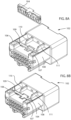
- FIG. 4A illustrates a perspective view of the female housing 3 of the electrical connector apparatus 1 showing the TPA 5 in the pre-set position.
- TPA 5 is located on the bottom, or underneath,of the female housing 3 in a bottom slot.
- the female housing has a set of terminal apertures for receiving therein at least a set of terminals.
- FIG. 4A further shows ribs 12, 13, 14, 15, 16, 17, and 18 that are provided on the bottom side of the female housing 3 and that surround the TPA 5 so as to prevent the TPA 5 from being physically pressed down into the final lock position during shipping, handling, or at any other time prior to reaching the operator.
- the ribs 12, 13, 14, 15, 16, 17, and 18 are located on the periphery of the TPA 5 so as to protect the TPA 5 from all sides.
- FIG 4B shows the female housing 3 of the electrical connector apparatus 1 once the TPA 5 has been moved to the final lock position.
- FIG. 5A illustrates a perspective view of the male housing 2 of the electrical connector apparatus 1 showing the TPA 4 in the pre-set position.
- the TPA 4 is protected by the ribs 6, 7, 8, 9, 10, and 11 from all sides. These ribs 6, 7, 8, 9, 10, and 11 are located on the periphery of the TPA 4 so as to protect the TPA 4 from being pressed down into the final lock position.
- FIG. 5B A perspective view of the male housing with the TPA 4 pressed down into the final lock position is shown in FIG. 5B .
- FIG. 6 , FIG. 7 , FIG. 8A, FIG. 8B , FIG, 9A, FIG. 9B , FIG. 10A, FIG. 10B , FIG. 11A and FIG. 11B illustrate an electrical connector apparatus according to the second embodiment of the present invention.
- the second embodiment of the present invention includes electrical connector apparatus 100,TPA 104, and TPA 105 having 16pins.
- the present invention is not limited to any specific number of pins for the electrical connector apparatus or TPA.
- the male housing, the female housing, the TPA, and the ribs operate identically to the first embodiment, as detailed above.
- Figure 6 illustrates an exploded perspective view of the electrical connector apparatus 100 according to the second embodiment of the present invention.
- Electrical connector apparatus 100 includes male housing 102, TPA 104, female housing 103, and TPA 105. Furthermore, Figure 6 shows the ribs 106, 107, 108, 109, 110, and 111 provided on the male housing 102 to protect the TPA 104.
- Figure 7 is a perspective view depicting the male housing 102 of the electrical connector apparatus 100 with the TPA 104 in the pre-set position.
- Ribs 106, 107, 108, 109, 110, and 111 are provided on the male housing 102 so as to surround the TPA 104 along the periphery of the TPA 104.
- Ribs 106, 107, 108, 109, 110, and 111 protect the TPA 104 so that the TPA 104 is not moved from a pre-set position to a final lock position during shipping and/or handling.
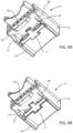
- Figure 8A illustrates a perspective view of the male housing 102 of the electrical connector apparatus 100 with the TPA 104 removed in order to fully see the placement of the TPA 104 in the male housing 102.
- Figure 8B shows the male housing 102 once the TPA 104 has been inserted into the male housing 102 and set in the pre-set position.
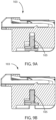
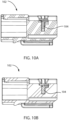
- the female housing 103 is also provided with ribs 112, 113, 114, 115, 116, 117, and 118 to protect the TPA 103 from being moved from a pre-set position, as shown in Figure 11A , to the final lock position, as shown in Figure 11B .
- These ribs 112, 113, 114, 115, 116, 117, and 118 are located on the periphery of the TPA 103 so as to create a physical barrier to protect the TPA 103 from all sides.
- the TPA 105 of the female housing 103 can be in either a pre-set position or a final lock position.
- the TPA 104 of the male housing 102 can be in either a pre-set position, as shown in Figure 10A , or a final lock position, as shown in Figure 10B .
Landscapes
- Connector Housings Or Holding Contact Members (AREA)
Claims (4)
- Buchsengehäuse (3; 103) einer elektrischen Verbindereinrichtung (1; 100), umfassend:einen Satz von Anschlussaperturen zum Aufnehmen mindestens eines Satzes von Anschlüssen darin;einen unteren Schlitz, der sich unterhalb des Buchsengehäuses (3; 103) befindet; undeine erste Anschlusspositionssicherungsvorrichtung (5; 105) (TPA), die innerhalb des unteren Schlitzes untergebracht ist,dadurch gekennzeichnet, dass das Buchsengehäuse ferner umfasst: Rippen (12, 13, 14, 15, 16, 17, 18; 112, 113, 114, 115, 116, 117, 118), die an dem Buchsengehäuse (3; 103) entlang eines Umfangs der TPA (5; 105) bereitgestellt sind, um die TPA (5; 105) vor physischem Kontakt zu schützen, wobei die erste TPA (5; 105) an jeder ihrer Außenseiten der Breite nach zwei rippenförmige Eingriffselemente einschließt, die sich davon erstrecken, um zu Ermöglichen, dass die erste TPA (5; 105) während des Transports des Buchsengehäuses (3; 103) in einer voreingestellten Position und in einer endgültigen Verriegelungsposition zum Ineingriffnehmen des Satzes von Anschlüssen ist.
- Steckergehäuse (2; 102) einer elektrischen Verbindereinrichtung (1; 100), umfassend:einen Satz von Anschlussaperturen zum Aufnehmen eines Satzes von anderen Anschlüssen darin;eine zweite Anschlusspositionssicherungsvorrichtung (4; 104) (TPA);eine Öffnung zum Aufnehmen der zweiten TPA (4; 104);ein erstes Ende, das den Satz von Anschlussaperturen zum Aufnehmen eines Satzes von anderen Anschlüssen darin aufweist;wobei das Steckergehäuse (2; 102) konfiguriert ist, um das Buchsengehäuse (3; 103) in einem zweiten Ende des Steckergehäuses (2; 102) aufzunehmen, dadurch gekennzeichnet, dass das Steckergehäuse ferner umfasst: Rippen (6, 7, 8, 9, 10, 11; 106, 107, 108, 109, 110, 111), die an dem Steckergehäuse (2; 102) entlang eines Umfangs der zweiten TPA (4; 104) bereitgestellt sind, um die zweite TPA (4; 104) vor physischem Kontakt zu schützen,wobei das Steckergehäuse (2; 102) konfiguriert ist, um das Buchsengehäuse (3; 103) in ein zweites Ende des Steckergehäuses (2; 102) aufzunehmen, wobei die zweite TPA (4; 104) an jeder ihrer Außenseiten der Breite nach zwei rippenförmige Eingriffselemente einschließt, die sich davon erstrecken, zum Ermöglichen, dass die zweite TPA (4; 104) während des Transports des Steckergehäuses (2; 102) in einer voreingestellten Position und in einer endgültigen Verriegelungsposition zum Ineingriffnehmen des Satzes von anderen Anschlüssen ist.
- Elektrische Verbindereinrichtung (1; 100), umfassend:ein Buchsengehäuse (3; 103) nach Anspruch 1 undein Steckergehäuse (2; 102) nach Anspruch 2,dadurch gekennzeichnet, dass die Rippen (6, 7, 8, 9, 10, 11; 106, 107, 108, 109, 110, 111) an dem Steckergehäuse (2; 102) konfiguriert sind, um sich über die zweite TPA hinaus zu erstrecken, wenn die zweite TPA in einer voreingestellten Position ist, um die zweite TPA (4; 104) vor physischem Kontakt zu schützen.
- Verfahren zum Zusammenbauen einer elektrischen Verbindereinrichtung (1; 100), umfassend die Schritte:Bereitstellen eines Buchsengehäuses (3; 103) nach Anspruch 1;Unterbringen einer ersten Anschlusspositionssicherungsvorrichtung (5; 105) (TPA) innerhalb eines unteren Schlitzes, der sich unterhalb des Buchsengehäuses (3; 103) befindet;Bereitstellen eines Steckergehäuses (2; 102) nach Anspruch 2;Unterbringen einer zweiten Anschlusspositionssicherungsvorrichtung (4; 104) (TPA) innerhalb einer Öffnung des Steckergehäuses (2; 102);Unterbringen des Buchsengehäuses (3; 103) in dem Steckergehäuse (2; 102); wobeider Schritt des Unterbringens der ersten TPA (5; 105) innerhalb des unteren Schlitzes, der sich unterhalb des Buchsengehäuses (3; 103) befindet, ferner den Schritt eines Versehens der ersten TPA (5; 105) an jeder ihrer Außenseiten der Breite nach mit zwei rippenförmigen Eingriffselementen umfasst, die sich davon erstrecken, zum Ermöglichen, dass die erste TPA (5; 105) während des Transports des Buchsengehäuses (3; 103) in einer voreingestellten Position und in einer endgültigen Verriegelungsposition zum Ineingriffnehmen des Satzes von Anschlüssen ist; und wobeider Schritt des Unterbringens der zweiten TPA (4; 104) innerhalb der Öffnung des Steckergehäuses (2; 102) ferner den Schritt des Versehens der zweiten TPA (4; 104) an jeder ihrer Außenseiten der Breite nach mit zwei rippenförmigen Eingriffselementen umfasst, die sich davon erstrecken, zum Ermöglichen, dass die zweite TPA (4; 104) in einer voreingestellten Position während des Transports des Steckergehäuses (2; 102) und in einer endgültigen Verriegelungsposition zum Ineingriffnehmen des Satzes von Anschlüssen ist.
Applications Claiming Priority (1)
| Application Number | Priority Date | Filing Date | Title |
|---|---|---|---|
| US15/405,654 US10109955B2 (en) | 2016-01-14 | 2017-01-13 | Electrical connector apparatus having a male housing and a female housing with ribs |
Publications (2)
| Publication Number | Publication Date |
|---|---|
| EP3316411A1 EP3316411A1 (de) | 2018-05-02 |
| EP3316411B1 true EP3316411B1 (de) | 2024-04-03 |
Family
ID=60673707
Family Applications (1)
| Application Number | Title | Priority Date | Filing Date |
|---|---|---|---|
| EP17207739.8A Active EP3316411B1 (de) | 2017-01-13 | 2017-12-15 | Elektrische verbindervorrichtung mit einem männlichen gehäuse und einem weiblichen gehäuse mit rippen und montagemethode |
Country Status (1)
| Country | Link |
|---|---|
| EP (1) | EP3316411B1 (de) |
Citations (1)
| Publication number | Priority date | Publication date | Assignee | Title |
|---|---|---|---|---|
| US20170207577A1 (en) * | 2016-01-14 | 2017-07-20 | J.S.T. Corporation | Electrical connector apparatus having a male housing and a female housing with ribs |
Family Cites Families (4)
| Publication number | Priority date | Publication date | Assignee | Title |
|---|---|---|---|---|
| US5830013A (en) * | 1997-03-07 | 1998-11-03 | Yazaki Corporation | Electric connector |
| JP3278051B2 (ja) * | 1997-12-25 | 2002-04-30 | 住友電装株式会社 | カバー付きコネクタ |
| US7278890B1 (en) * | 2006-07-26 | 2007-10-09 | Delphi Technologies, Inc. | Electrical connector with secondary lock |
| US10283909B2 (en) * | 2015-12-21 | 2019-05-07 | J.S.T. Corporation | Method of operating a connector latch |
-
2017
- 2017-12-15 EP EP17207739.8A patent/EP3316411B1/de active Active
Patent Citations (1)
| Publication number | Priority date | Publication date | Assignee | Title |
|---|---|---|---|---|
| US20170207577A1 (en) * | 2016-01-14 | 2017-07-20 | J.S.T. Corporation | Electrical connector apparatus having a male housing and a female housing with ribs |
Also Published As
| Publication number | Publication date |
|---|---|
| EP3316411A1 (de) | 2018-05-02 |
Similar Documents
| Publication | Publication Date | Title |
|---|---|---|
| US10109955B2 (en) | Electrical connector apparatus having a male housing and a female housing with ribs | |
| US9954311B2 (en) | Electric connector | |
| KR101575390B1 (ko) | 보호판을 구비한 커넥터 | |
| EP2899813B1 (de) | Steckverbinder | |
| CN110832708B (zh) | 带有端子对准板和辅助锁检测的电连接器 | |
| EP2930793A1 (de) | Steckverbinder | |
| EP3648259B1 (de) | Elektrischer verbinder mit verriegelungen und anschlusspositionsvorsprüngen auf einem klappdeckel | |
| US20080207024A1 (en) | Connector and a connector assembly | |
| US11031732B2 (en) | Lever-type connector | |
| CN108832427A (zh) | 用于安全系统的连接器组件 | |
| US9843126B1 (en) | Connector housing assemblies with access hood and push surface | |
| EP3316411B1 (de) | Elektrische verbindervorrichtung mit einem männlichen gehäuse und einem weiblichen gehäuse mit rippen und montagemethode | |
| US9986635B2 (en) | Assembly and electronic device with conductive mesh | |
| CN100530845C (zh) | 触发系统的接插件和短路组件 | |
| US20120258626A1 (en) | Housing Insert Contact Protection | |
| TWM447019U (zh) | 具有防呆結構的網路電連接器 | |
| EP2705580B1 (de) | Elektrischer steckverbinder mit einem schlüssel zur vermeidung von kontaktschäden | |
| EP3113295B1 (de) | Verbinder | |
| EP2937949B1 (de) | Verbinder für kraftfahrzeuge und verfahren zur montage von dieser verbindung | |
| WO2015121847A1 (en) | Improved electrical connector | |
| US20090311882A1 (en) | Electrical connector assembly with pick-up cap | |
| JP2021150012A (ja) | 接続端子 | |
| CN107431305A (zh) | 电连接器 | |
| CN105742891A (zh) | 电连接器组件及其对接方法 | |
| KR20150067423A (ko) | 커넥터 |
Legal Events
| Date | Code | Title | Description |
|---|---|---|---|
| PUAI | Public reference made under article 153(3) epc to a published international application that has entered the european phase |
Free format text: ORIGINAL CODE: 0009012 |
|
| STAA | Information on the status of an ep patent application or granted ep patent |
Free format text: STATUS: THE APPLICATION HAS BEEN PUBLISHED |
|
| AK | Designated contracting states |
Kind code of ref document: A1 Designated state(s): AL AT BE BG CH CY CZ DE DK EE ES FI FR GB GR HR HU IE IS IT LI LT LU LV MC MK MT NL NO PL PT RO RS SE SI SK SM TR |
|
| AX | Request for extension of the european patent |
Extension state: BA ME |
|
| STAA | Information on the status of an ep patent application or granted ep patent |
Free format text: STATUS: REQUEST FOR EXAMINATION WAS MADE |
|
| 17P | Request for examination filed |
Effective date: 20180810 |
|
| RBV | Designated contracting states (corrected) |
Designated state(s): AL AT BE BG CH CY CZ DE DK EE ES FI FR GB GR HR HU IE IS IT LI LT LU LV MC MK MT NL NO PL PT RO RS SE SI SK SM TR |
|
| STAA | Information on the status of an ep patent application or granted ep patent |
Free format text: STATUS: EXAMINATION IS IN PROGRESS |
|
| 17Q | First examination report despatched |
Effective date: 20190117 |
|
| RIC1 | Information provided on ipc code assigned before grant |
Ipc: H01R 43/26 20060101ALN20210915BHEP Ipc: H01R 13/436 20060101AFI20210915BHEP |
|
| GRAP | Despatch of communication of intention to grant a patent |
Free format text: ORIGINAL CODE: EPIDOSNIGR1 |
|
| STAA | Information on the status of an ep patent application or granted ep patent |
Free format text: STATUS: GRANT OF PATENT IS INTENDED |
|
| RIC1 | Information provided on ipc code assigned before grant |
Ipc: H01R 43/26 20060101ALN20230918BHEP Ipc: H01R 13/436 20060101AFI20230918BHEP |
|
| RIC1 | Information provided on ipc code assigned before grant |
Ipc: H01R 43/26 20060101ALN20230925BHEP Ipc: H01R 13/436 20060101AFI20230925BHEP |
|
| INTG | Intention to grant announced |
Effective date: 20231024 |
|
| GRAS | Grant fee paid |
Free format text: ORIGINAL CODE: EPIDOSNIGR3 |
|
| GRAA | (expected) grant |
Free format text: ORIGINAL CODE: 0009210 |
|
| STAA | Information on the status of an ep patent application or granted ep patent |
Free format text: STATUS: THE PATENT HAS BEEN GRANTED |
|
| AK | Designated contracting states |
Kind code of ref document: B1 Designated state(s): AL AT BE BG CH CY CZ DE DK EE ES FI FR GB GR HR HU IE IS IT LI LT LU LV MC MK MT NL NO PL PT RO RS SE SI SK SM TR |
|
| REG | Reference to a national code |
Ref country code: GB Ref legal event code: FG4D |
|
| REG | Reference to a national code |
Ref country code: CH Ref legal event code: EP |
|
| REG | Reference to a national code |
Ref country code: DE Ref legal event code: R096 Ref document number: 602017080547 Country of ref document: DE |
|
| REG | Reference to a national code |
Ref country code: IE Ref legal event code: FG4D |
|
| REG | Reference to a national code |
Ref country code: LT Ref legal event code: MG9D |
|
| REG | Reference to a national code |
Ref country code: NL Ref legal event code: MP Effective date: 20240403 |
|
| REG | Reference to a national code |
Ref country code: AT Ref legal event code: MK05 Ref document number: 1673426 Country of ref document: AT Kind code of ref document: T Effective date: 20240403 |
|
| PG25 | Lapsed in a contracting state [announced via postgrant information from national office to epo] |
Ref country code: NL Free format text: LAPSE BECAUSE OF FAILURE TO SUBMIT A TRANSLATION OF THE DESCRIPTION OR TO PAY THE FEE WITHIN THE PRESCRIBED TIME-LIMIT Effective date: 20240403 |
|
| PG25 | Lapsed in a contracting state [announced via postgrant information from national office to epo] |
Ref country code: NL Free format text: LAPSE BECAUSE OF FAILURE TO SUBMIT A TRANSLATION OF THE DESCRIPTION OR TO PAY THE FEE WITHIN THE PRESCRIBED TIME-LIMIT Effective date: 20240403 |
|
| PG25 | Lapsed in a contracting state [announced via postgrant information from national office to epo] |
Ref country code: IS Free format text: LAPSE BECAUSE OF FAILURE TO SUBMIT A TRANSLATION OF THE DESCRIPTION OR TO PAY THE FEE WITHIN THE PRESCRIBED TIME-LIMIT Effective date: 20240803 |
|
| PG25 | Lapsed in a contracting state [announced via postgrant information from national office to epo] |
Ref country code: BG Free format text: LAPSE BECAUSE OF FAILURE TO SUBMIT A TRANSLATION OF THE DESCRIPTION OR TO PAY THE FEE WITHIN THE PRESCRIBED TIME-LIMIT Effective date: 20240403 |
|
| PG25 | Lapsed in a contracting state [announced via postgrant information from national office to epo] |
Ref country code: HR Free format text: LAPSE BECAUSE OF FAILURE TO SUBMIT A TRANSLATION OF THE DESCRIPTION OR TO PAY THE FEE WITHIN THE PRESCRIBED TIME-LIMIT Effective date: 20240403 Ref country code: FI Free format text: LAPSE BECAUSE OF FAILURE TO SUBMIT A TRANSLATION OF THE DESCRIPTION OR TO PAY THE FEE WITHIN THE PRESCRIBED TIME-LIMIT Effective date: 20240403 |
|
| PG25 | Lapsed in a contracting state [announced via postgrant information from national office to epo] |
Ref country code: GR Free format text: LAPSE BECAUSE OF FAILURE TO SUBMIT A TRANSLATION OF THE DESCRIPTION OR TO PAY THE FEE WITHIN THE PRESCRIBED TIME-LIMIT Effective date: 20240704 |
|
| PG25 | Lapsed in a contracting state [announced via postgrant information from national office to epo] |
Ref country code: PT Free format text: LAPSE BECAUSE OF FAILURE TO SUBMIT A TRANSLATION OF THE DESCRIPTION OR TO PAY THE FEE WITHIN THE PRESCRIBED TIME-LIMIT Effective date: 20240805 |
|
| PG25 | Lapsed in a contracting state [announced via postgrant information from national office to epo] |
Ref country code: ES Free format text: LAPSE BECAUSE OF FAILURE TO SUBMIT A TRANSLATION OF THE DESCRIPTION OR TO PAY THE FEE WITHIN THE PRESCRIBED TIME-LIMIT Effective date: 20240403 |
|
| PG25 | Lapsed in a contracting state [announced via postgrant information from national office to epo] |
Ref country code: CZ Free format text: LAPSE BECAUSE OF FAILURE TO SUBMIT A TRANSLATION OF THE DESCRIPTION OR TO PAY THE FEE WITHIN THE PRESCRIBED TIME-LIMIT Effective date: 20240403 |
|
| PG25 | Lapsed in a contracting state [announced via postgrant information from national office to epo] |
Ref country code: AT Free format text: LAPSE BECAUSE OF FAILURE TO SUBMIT A TRANSLATION OF THE DESCRIPTION OR TO PAY THE FEE WITHIN THE PRESCRIBED TIME-LIMIT Effective date: 20240403 |
|
| PG25 | Lapsed in a contracting state [announced via postgrant information from national office to epo] |
Ref country code: PL Free format text: LAPSE BECAUSE OF FAILURE TO SUBMIT A TRANSLATION OF THE DESCRIPTION OR TO PAY THE FEE WITHIN THE PRESCRIBED TIME-LIMIT Effective date: 20240403 |
|
| PG25 | Lapsed in a contracting state [announced via postgrant information from national office to epo] |
Ref country code: LV Free format text: LAPSE BECAUSE OF FAILURE TO SUBMIT A TRANSLATION OF THE DESCRIPTION OR TO PAY THE FEE WITHIN THE PRESCRIBED TIME-LIMIT Effective date: 20240403 |
|
| PG25 | Lapsed in a contracting state [announced via postgrant information from national office to epo] |
Ref country code: PT Free format text: LAPSE BECAUSE OF FAILURE TO SUBMIT A TRANSLATION OF THE DESCRIPTION OR TO PAY THE FEE WITHIN THE PRESCRIBED TIME-LIMIT Effective date: 20240805 Ref country code: PL Free format text: LAPSE BECAUSE OF FAILURE TO SUBMIT A TRANSLATION OF THE DESCRIPTION OR TO PAY THE FEE WITHIN THE PRESCRIBED TIME-LIMIT Effective date: 20240403 Ref country code: NO Free format text: LAPSE BECAUSE OF FAILURE TO SUBMIT A TRANSLATION OF THE DESCRIPTION OR TO PAY THE FEE WITHIN THE PRESCRIBED TIME-LIMIT Effective date: 20240703 Ref country code: LV Free format text: LAPSE BECAUSE OF FAILURE TO SUBMIT A TRANSLATION OF THE DESCRIPTION OR TO PAY THE FEE WITHIN THE PRESCRIBED TIME-LIMIT Effective date: 20240403 Ref country code: IS Free format text: LAPSE BECAUSE OF FAILURE TO SUBMIT A TRANSLATION OF THE DESCRIPTION OR TO PAY THE FEE WITHIN THE PRESCRIBED TIME-LIMIT Effective date: 20240803 Ref country code: HR Free format text: LAPSE BECAUSE OF FAILURE TO SUBMIT A TRANSLATION OF THE DESCRIPTION OR TO PAY THE FEE WITHIN THE PRESCRIBED TIME-LIMIT Effective date: 20240403 Ref country code: GR Free format text: LAPSE BECAUSE OF FAILURE TO SUBMIT A TRANSLATION OF THE DESCRIPTION OR TO PAY THE FEE WITHIN THE PRESCRIBED TIME-LIMIT Effective date: 20240704 Ref country code: FI Free format text: LAPSE BECAUSE OF FAILURE TO SUBMIT A TRANSLATION OF THE DESCRIPTION OR TO PAY THE FEE WITHIN THE PRESCRIBED TIME-LIMIT Effective date: 20240403 Ref country code: ES Free format text: LAPSE BECAUSE OF FAILURE TO SUBMIT A TRANSLATION OF THE DESCRIPTION OR TO PAY THE FEE WITHIN THE PRESCRIBED TIME-LIMIT Effective date: 20240403 Ref country code: CZ Free format text: LAPSE BECAUSE OF FAILURE TO SUBMIT A TRANSLATION OF THE DESCRIPTION OR TO PAY THE FEE WITHIN THE PRESCRIBED TIME-LIMIT Effective date: 20240403 Ref country code: BG Free format text: LAPSE BECAUSE OF FAILURE TO SUBMIT A TRANSLATION OF THE DESCRIPTION OR TO PAY THE FEE WITHIN THE PRESCRIBED TIME-LIMIT Effective date: 20240403 Ref country code: AT Free format text: LAPSE BECAUSE OF FAILURE TO SUBMIT A TRANSLATION OF THE DESCRIPTION OR TO PAY THE FEE WITHIN THE PRESCRIBED TIME-LIMIT Effective date: 20240403 Ref country code: RS Free format text: LAPSE BECAUSE OF FAILURE TO SUBMIT A TRANSLATION OF THE DESCRIPTION OR TO PAY THE FEE WITHIN THE PRESCRIBED TIME-LIMIT Effective date: 20240703 |
|
| REG | Reference to a national code |
Ref country code: DE Ref legal event code: R097 Ref document number: 602017080547 Country of ref document: DE |
|
| PG25 | Lapsed in a contracting state [announced via postgrant information from national office to epo] |
Ref country code: DK Free format text: LAPSE BECAUSE OF FAILURE TO SUBMIT A TRANSLATION OF THE DESCRIPTION OR TO PAY THE FEE WITHIN THE PRESCRIBED TIME-LIMIT Effective date: 20240403 |
|
| PG25 | Lapsed in a contracting state [announced via postgrant information from national office to epo] |
Ref country code: EE Free format text: LAPSE BECAUSE OF FAILURE TO SUBMIT A TRANSLATION OF THE DESCRIPTION OR TO PAY THE FEE WITHIN THE PRESCRIBED TIME-LIMIT Effective date: 20240403 |
|
| PG25 | Lapsed in a contracting state [announced via postgrant information from national office to epo] |
Ref country code: RO Free format text: LAPSE BECAUSE OF FAILURE TO SUBMIT A TRANSLATION OF THE DESCRIPTION OR TO PAY THE FEE WITHIN THE PRESCRIBED TIME-LIMIT Effective date: 20240403 Ref country code: SK Free format text: LAPSE BECAUSE OF FAILURE TO SUBMIT A TRANSLATION OF THE DESCRIPTION OR TO PAY THE FEE WITHIN THE PRESCRIBED TIME-LIMIT Effective date: 20240403 |
|
| PG25 | Lapsed in a contracting state [announced via postgrant information from national office to epo] |
Ref country code: SM Free format text: LAPSE BECAUSE OF FAILURE TO SUBMIT A TRANSLATION OF THE DESCRIPTION OR TO PAY THE FEE WITHIN THE PRESCRIBED TIME-LIMIT Effective date: 20240403 |
|
| PG25 | Lapsed in a contracting state [announced via postgrant information from national office to epo] |
Ref country code: SM Free format text: LAPSE BECAUSE OF FAILURE TO SUBMIT A TRANSLATION OF THE DESCRIPTION OR TO PAY THE FEE WITHIN THE PRESCRIBED TIME-LIMIT Effective date: 20240403 Ref country code: SK Free format text: LAPSE BECAUSE OF FAILURE TO SUBMIT A TRANSLATION OF THE DESCRIPTION OR TO PAY THE FEE WITHIN THE PRESCRIBED TIME-LIMIT Effective date: 20240403 Ref country code: RO Free format text: LAPSE BECAUSE OF FAILURE TO SUBMIT A TRANSLATION OF THE DESCRIPTION OR TO PAY THE FEE WITHIN THE PRESCRIBED TIME-LIMIT Effective date: 20240403 Ref country code: EE Free format text: LAPSE BECAUSE OF FAILURE TO SUBMIT A TRANSLATION OF THE DESCRIPTION OR TO PAY THE FEE WITHIN THE PRESCRIBED TIME-LIMIT Effective date: 20240403 Ref country code: DK Free format text: LAPSE BECAUSE OF FAILURE TO SUBMIT A TRANSLATION OF THE DESCRIPTION OR TO PAY THE FEE WITHIN THE PRESCRIBED TIME-LIMIT Effective date: 20240403 |
|
| PLBE | No opposition filed within time limit |
Free format text: ORIGINAL CODE: 0009261 |
|
| STAA | Information on the status of an ep patent application or granted ep patent |
Free format text: STATUS: NO OPPOSITION FILED WITHIN TIME LIMIT |
|
| 26N | No opposition filed |
Effective date: 20250106 |
|
| PG25 | Lapsed in a contracting state [announced via postgrant information from national office to epo] |
Ref country code: SI Free format text: LAPSE BECAUSE OF FAILURE TO SUBMIT A TRANSLATION OF THE DESCRIPTION OR TO PAY THE FEE WITHIN THE PRESCRIBED TIME-LIMIT Effective date: 20240403 |
|
| PG25 | Lapsed in a contracting state [announced via postgrant information from national office to epo] |
Ref country code: MC Free format text: LAPSE BECAUSE OF FAILURE TO SUBMIT A TRANSLATION OF THE DESCRIPTION OR TO PAY THE FEE WITHIN THE PRESCRIBED TIME-LIMIT Effective date: 20240403 |
|
| REG | Reference to a national code |
Ref country code: CH Ref legal event code: PL |
|
| PG25 | Lapsed in a contracting state [announced via postgrant information from national office to epo] |
Ref country code: LU Free format text: LAPSE BECAUSE OF NON-PAYMENT OF DUE FEES Effective date: 20241215 |
|
| PG25 | Lapsed in a contracting state [announced via postgrant information from national office to epo] |
Ref country code: SE Free format text: LAPSE BECAUSE OF FAILURE TO SUBMIT A TRANSLATION OF THE DESCRIPTION OR TO PAY THE FEE WITHIN THE PRESCRIBED TIME-LIMIT Effective date: 20240403 |
|
| REG | Reference to a national code |
Ref country code: BE Ref legal event code: MM Effective date: 20241231 |
|
| PG25 | Lapsed in a contracting state [announced via postgrant information from national office to epo] |
Ref country code: BE Free format text: LAPSE BECAUSE OF NON-PAYMENT OF DUE FEES Effective date: 20241231 |
|
| PG25 | Lapsed in a contracting state [announced via postgrant information from national office to epo] |
Ref country code: CH Free format text: LAPSE BECAUSE OF NON-PAYMENT OF DUE FEES Effective date: 20241231 |
|
| PG25 | Lapsed in a contracting state [announced via postgrant information from national office to epo] |
Ref country code: IE Free format text: LAPSE BECAUSE OF NON-PAYMENT OF DUE FEES Effective date: 20241215 |
|
| PGFP | Annual fee paid to national office [announced via postgrant information from national office to epo] |
Ref country code: DE Payment date: 20251211 Year of fee payment: 9 |
|
| PGFP | Annual fee paid to national office [announced via postgrant information from national office to epo] |
Ref country code: GB Payment date: 20251219 Year of fee payment: 9 |
|
| PG25 | Lapsed in a contracting state [announced via postgrant information from national office to epo] |
Ref country code: IT Free format text: LAPSE BECAUSE OF NON-PAYMENT OF DUE FEES Effective date: 20241215 |
|
| PGFP | Annual fee paid to national office [announced via postgrant information from national office to epo] |
Ref country code: FR Payment date: 20251229 Year of fee payment: 9 |
|
| PG25 | Lapsed in a contracting state [announced via postgrant information from national office to epo] |
Ref country code: IT Free format text: LAPSE BECAUSE OF NON-PAYMENT OF DUE FEES Effective date: 20241215 |
|
| PGFP | Annual fee paid to national office [announced via postgrant information from national office to epo] |
Ref country code: IT Payment date: 20251223 Year of fee payment: 9 |
|
| PGRI | Patent reinstated in contracting state [announced from national office to epo] |
Ref country code: IT Effective date: 20250430 |