EP3316418A2 - Auslassvorrichtung - Google Patents
Auslassvorrichtung Download PDFInfo
- Publication number
- EP3316418A2 EP3316418A2 EP17198333.1A EP17198333A EP3316418A2 EP 3316418 A2 EP3316418 A2 EP 3316418A2 EP 17198333 A EP17198333 A EP 17198333A EP 3316418 A2 EP3316418 A2 EP 3316418A2
- Authority
- EP
- European Patent Office
- Prior art keywords
- voice
- case
- outlet device
- counterweight
- outlet
- Prior art date
- Legal status (The legal status is an assumption and is not a legal conclusion. Google has not performed a legal analysis and makes no representation as to the accuracy of the status listed.)
- Withdrawn
Links
Images


Classifications
-
- H—ELECTRICITY
- H01—ELECTRIC ELEMENTS
- H01R—ELECTRICALLY-CONDUCTIVE CONNECTIONS; STRUCTURAL ASSOCIATIONS OF A PLURALITY OF MUTUALLY-INSULATED ELECTRICAL CONNECTING ELEMENTS; COUPLING DEVICES; CURRENT COLLECTORS
- H01R25/00—Coupling parts adapted for simultaneous co-operation with two or more identical counterparts, e.g. for distributing energy to two or more circuits
- H01R25/006—Coupling parts adapted for simultaneous co-operation with two or more identical counterparts, e.g. for distributing energy to two or more circuits the coupling part being secured to apparatus or structure, e.g. duplex wall receptacle
-
- H—ELECTRICITY
- H01—ELECTRIC ELEMENTS
- H01R—ELECTRICALLY-CONDUCTIVE CONNECTIONS; STRUCTURAL ASSOCIATIONS OF A PLURALITY OF MUTUALLY-INSULATED ELECTRICAL CONNECTING ELEMENTS; COUPLING DEVICES; CURRENT COLLECTORS
- H01R13/00—Details of coupling devices of the kinds covered by groups H01R12/70 or H01R24/00 - H01R33/00
- H01R13/46—Bases; Cases
- H01R13/514—Bases; Cases composed as a modular blocks or assembly, i.e. composed of co-operating parts provided with contact members or holding contact members between them
-
- G—PHYSICS
- G05—CONTROLLING; REGULATING
- G05B—CONTROL OR REGULATING SYSTEMS IN GENERAL; FUNCTIONAL ELEMENTS OF SUCH SYSTEMS; MONITORING OR TESTING ARRANGEMENTS FOR SUCH SYSTEMS OR ELEMENTS
- G05B13/00—Adaptive control systems, i.e. systems automatically adjusting themselves to have a performance which is optimum according to some preassigned criterion
- G05B13/02—Adaptive control systems, i.e. systems automatically adjusting themselves to have a performance which is optimum according to some preassigned criterion electric
-
- G—PHYSICS
- G10—MUSICAL INSTRUMENTS; ACOUSTICS
- G10L—SPEECH ANALYSIS TECHNIQUES OR SPEECH SYNTHESIS; SPEECH RECOGNITION; SPEECH OR VOICE PROCESSING TECHNIQUES; SPEECH OR AUDIO CODING OR DECODING
- G10L15/00—Speech recognition
- G10L15/22—Procedures used during a speech recognition process, e.g. man-machine dialogue
-
- H—ELECTRICITY
- H01—ELECTRIC ELEMENTS
- H01R—ELECTRICALLY-CONDUCTIVE CONNECTIONS; STRUCTURAL ASSOCIATIONS OF A PLURALITY OF MUTUALLY-INSULATED ELECTRICAL CONNECTING ELEMENTS; COUPLING DEVICES; CURRENT COLLECTORS
- H01R13/00—Details of coupling devices of the kinds covered by groups H01R12/70 or H01R24/00 - H01R33/00
- H01R13/62—Means for facilitating engagement or disengagement of coupling parts or for holding them in engagement
- H01R13/639—Additional means for holding or locking coupling parts together, after engagement, e.g. separate keylock, retainer strap
- H01R13/6395—Additional means for holding or locking coupling parts together, after engagement, e.g. separate keylock, retainer strap for wall or panel outlets
-
- H—ELECTRICITY
- H01—ELECTRIC ELEMENTS
- H01R—ELECTRICALLY-CONDUCTIVE CONNECTIONS; STRUCTURAL ASSOCIATIONS OF A PLURALITY OF MUTUALLY-INSULATED ELECTRICAL CONNECTING ELEMENTS; COUPLING DEVICES; CURRENT COLLECTORS
- H01R13/00—Details of coupling devices of the kinds covered by groups H01R12/70 or H01R24/00 - H01R33/00
- H01R13/66—Structural association with built-in electrical component
- H01R13/665—Structural association with built-in electrical component with built-in electronic circuit
- H01R13/6675—Structural association with built-in electrical component with built-in electronic circuit with built-in power supply
-
- H—ELECTRICITY
- H01—ELECTRIC ELEMENTS
- H01R—ELECTRICALLY-CONDUCTIVE CONNECTIONS; STRUCTURAL ASSOCIATIONS OF A PLURALITY OF MUTUALLY-INSULATED ELECTRICAL CONNECTING ELEMENTS; COUPLING DEVICES; CURRENT COLLECTORS
- H01R13/00—Details of coupling devices of the kinds covered by groups H01R12/70 or H01R24/00 - H01R33/00
- H01R13/66—Structural association with built-in electrical component
- H01R13/665—Structural association with built-in electrical component with built-in electronic circuit
- H01R13/6683—Structural association with built-in electrical component with built-in electronic circuit with built-in sensor
-
- H—ELECTRICITY
- H01—ELECTRIC ELEMENTS
- H01R—ELECTRICALLY-CONDUCTIVE CONNECTIONS; STRUCTURAL ASSOCIATIONS OF A PLURALITY OF MUTUALLY-INSULATED ELECTRICAL CONNECTING ELEMENTS; COUPLING DEVICES; CURRENT COLLECTORS
- H01R13/00—Details of coupling devices of the kinds covered by groups H01R12/70 or H01R24/00 - H01R33/00
- H01R13/73—Means for mounting coupling parts to apparatus or structures, e.g. to a wall
-
- H—ELECTRICITY
- H01—ELECTRIC ELEMENTS
- H01R—ELECTRICALLY-CONDUCTIVE CONNECTIONS; STRUCTURAL ASSOCIATIONS OF A PLURALITY OF MUTUALLY-INSULATED ELECTRICAL CONNECTING ELEMENTS; COUPLING DEVICES; CURRENT COLLECTORS
- H01R24/00—Two-part coupling devices, or either of their cooperating parts, characterised by their overall structure
- H01R24/66—Two-part coupling devices, or either of their cooperating parts, characterised by their overall structure with pins, blades or analogous contacts and secured to apparatus or structure, e.g. to a wall
-
- H—ELECTRICITY
- H01—ELECTRIC ELEMENTS
- H01R—ELECTRICALLY-CONDUCTIVE CONNECTIONS; STRUCTURAL ASSOCIATIONS OF A PLURALITY OF MUTUALLY-INSULATED ELECTRICAL CONNECTING ELEMENTS; COUPLING DEVICES; CURRENT COLLECTORS
- H01R24/00—Two-part coupling devices, or either of their cooperating parts, characterised by their overall structure
- H01R24/76—Two-part coupling devices, or either of their cooperating parts, characterised by their overall structure with sockets, clips or analogous contacts and secured to apparatus or structure, e.g. to a wall
-
- H—ELECTRICITY
- H01—ELECTRIC ELEMENTS
- H01R—ELECTRICALLY-CONDUCTIVE CONNECTIONS; STRUCTURAL ASSOCIATIONS OF A PLURALITY OF MUTUALLY-INSULATED ELECTRICAL CONNECTING ELEMENTS; COUPLING DEVICES; CURRENT COLLECTORS
- H01R25/00—Coupling parts adapted for simultaneous co-operation with two or more identical counterparts, e.g. for distributing energy to two or more circuits
- H01R25/003—Coupling parts adapted for simultaneous co-operation with two or more identical counterparts, e.g. for distributing energy to two or more circuits the coupling part being secured only to wires or cables
-
- H—ELECTRICITY
- H01—ELECTRIC ELEMENTS
- H01R—ELECTRICALLY-CONDUCTIVE CONNECTIONS; STRUCTURAL ASSOCIATIONS OF A PLURALITY OF MUTUALLY-INSULATED ELECTRICAL CONNECTING ELEMENTS; COUPLING DEVICES; CURRENT COLLECTORS
- H01R35/00—Flexible or turnable line connectors, i.e. the rotation angle being limited
- H01R35/02—Flexible line connectors without frictional contact members
-
- H—ELECTRICITY
- H02—GENERATION; CONVERSION OR DISTRIBUTION OF ELECTRIC POWER
- H02G—INSTALLATION OF ELECTRIC CABLES OR LINES, OR OF COMBINED OPTICAL AND ELECTRIC CABLES OR LINES
- H02G3/00—Installations of electric cables or lines or protective tubing therefor in or on buildings, equivalent structures or vehicles
- H02G3/02—Details
- H02G3/08—Distribution boxes; Connection or junction boxes
- H02G3/081—Bases, casings or covers
-
- H—ELECTRICITY
- H05—ELECTRIC TECHNIQUES NOT OTHERWISE PROVIDED FOR
- H05K—PRINTED CIRCUITS; CASINGS OR CONSTRUCTIONAL DETAILS OF ELECTRIC APPARATUS; MANUFACTURE OF ASSEMBLAGES OF ELECTRICAL COMPONENTS
- H05K7/00—Constructional details common to different types of electric apparatus
- H05K7/20—Modifications to facilitate cooling, ventilating, or heating
- H05K7/20009—Modifications to facilitate cooling, ventilating, or heating using a gaseous coolant in electronic enclosures
- H05K7/20136—Forced ventilation, e.g. by fans
- H05K7/20145—Means for directing air flow, e.g. ducts, deflectors, plenum or guides
-
- G—PHYSICS
- G10—MUSICAL INSTRUMENTS; ACOUSTICS
- G10L—SPEECH ANALYSIS TECHNIQUES OR SPEECH SYNTHESIS; SPEECH RECOGNITION; SPEECH OR VOICE PROCESSING TECHNIQUES; SPEECH OR AUDIO CODING OR DECODING
- G10L15/00—Speech recognition
- G10L15/22—Procedures used during a speech recognition process, e.g. man-machine dialogue
- G10L2015/223—Execution procedure of a spoken command
-
- H—ELECTRICITY
- H01—ELECTRIC ELEMENTS
- H01R—ELECTRICALLY-CONDUCTIVE CONNECTIONS; STRUCTURAL ASSOCIATIONS OF A PLURALITY OF MUTUALLY-INSULATED ELECTRICAL CONNECTING ELEMENTS; COUPLING DEVICES; CURRENT COLLECTORS
- H01R13/00—Details of coupling devices of the kinds covered by groups H01R12/70 or H01R24/00 - H01R33/00
- H01R13/66—Structural association with built-in electrical component
- H01R13/70—Structural association with built-in electrical component with built-in switch
-
- H—ELECTRICITY
- H01—ELECTRIC ELEMENTS
- H01R—ELECTRICALLY-CONDUCTIVE CONNECTIONS; STRUCTURAL ASSOCIATIONS OF A PLURALITY OF MUTUALLY-INSULATED ELECTRICAL CONNECTING ELEMENTS; COUPLING DEVICES; CURRENT COLLECTORS
- H01R2103/00—Two poles
-
- H—ELECTRICITY
- H01—ELECTRIC ELEMENTS
- H01R—ELECTRICALLY-CONDUCTIVE CONNECTIONS; STRUCTURAL ASSOCIATIONS OF A PLURALITY OF MUTUALLY-INSULATED ELECTRICAL CONNECTING ELEMENTS; COUPLING DEVICES; CURRENT COLLECTORS
- H01R24/00—Two-part coupling devices, or either of their cooperating parts, characterised by their overall structure
- H01R24/60—Contacts spaced along planar side wall transverse to longitudinal axis of engagement
- H01R24/62—Sliding engagements with one side only, e.g. modular jack coupling devices
-
- H—ELECTRICITY
- H02—GENERATION; CONVERSION OR DISTRIBUTION OF ELECTRIC POWER
- H02G—INSTALLATION OF ELECTRIC CABLES OR LINES, OR OF COMBINED OPTICAL AND ELECTRIC CABLES OR LINES
- H02G3/00—Installations of electric cables or lines or protective tubing therefor in or on buildings, equivalent structures or vehicles
- H02G3/02—Details
- H02G3/08—Distribution boxes; Connection or junction boxes
- H02G3/18—Distribution boxes; Connection or junction boxes providing line outlets
Definitions
- the present disclosure relates to an outlet; in particular, to an outlet device for hanging on a plate.
- the structure of a conventional outlet device has not undergone any significant change in recent years, thus limiting the functions thereof.
- the conventional outlet device when the conventional outlet device is applied to a desk, the conventional outlet device does not have any additional function other than the function of supplying power.
- the present disclosure provides an outlet device to solve the drawback associated with conventional outlet devices.
- the present disclosure provides an outlet device for being hung on a plate, in which the outlet device includes a counterweight portion, a hanging portion, an extending portion, a voice controlling module, and a power cord.
- the counterweight portion includes an outlet unit.
- the hanging portion is arranged distant from the counterweight portion.
- the extending portion has two opposite ends respectively connected to the counterweight portion and the hanging portion.
- a free end of the hanging portion is arranged distant from the extending portion by a lateral distance, the extending portion has a width parallel to the lateral distance, and the width is less than or equal to the lateral distance.
- the voice controlling module includes a voice receiver installed to the hanging portion for receiving a voice signal.
- the voice controlling module is configured to control an electronic device according to the voice signal received from the voice receiver.
- the power cord is electrically connected to the outlet unit and the voice controlling module.
- the power cord has an end connected to the counterweight portion and an opposite end used for detachably inserting into an external power supplying outlet.
- the present disclosure also provides an outlet device, which includes a counterweight portion, a hanging portion, an extending portion, and a voice controlling module.
- the hanging portion is arranged distant from the counterweight portion. At least one of the counterweight portion and the hanging portion is provided with an outlet unit.
- the extending portion has two opposite ends respectively connected to the counterweight portion and the hanging portion.
- the voice controlling module includes a voice receiver installed in the hanging portion or the extending portion for receiving a voice signal. The voice controlling module is configured to control an electronic device according to the voice signal received from the voice receiver.
- the present disclosure further provides an outlet device, which includes a counterweight portion, a hanging portion, an extending portion, an AC/DC convertor, a wireless controller, and a speaker.
- the hanging portion is arranged distant from the counterweight portion. At least one of the counterweight portion and the hanging portion is provided with an outlet unit.
- the extending portion has two opposite ends respectively connected to the counterweight portion and the hanging portion.
- the AC/DC convertor and the wireless controller are electrically connected to each other.
- the speaker is electrically connected to the AC/DC convertor and the wireless controller.
- the wireless controller is configured to control the speaker by receiving an external signal, and the speaker, the AC/DC convertor, and the wireless controller are installed in at least one of the counterweight portion, the hanging portion, and the extending portion.
- the outlet device of the present disclosure is provided to wirelessly control an electronic device or a speaker (i.e., the electronic device is controlled by the voice controlling module, or the speaker is controlled by the wireless controller), thereby increasing the value added of the outlet device.
- the voice controlling module of the outlet device can be wirelessly connected to the expansion outlets, such that a user can control the expansion outlets by speaking to the voice controlling module.
- Fig. 1 illustrates a schematic view of the present disclosure
- Figs. 2 to 17 illustrate five embodiments of the present disclosure.
- References are hereunder made to the detailed descriptions and appended drawings in connection with the present disclosure.
- the appended drawings are merely provided for exemplary purposes, and should not be construed as restricting the scope of the present disclosure.
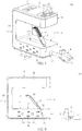
- the present disclosure provides an outlet device 100 for being hung on a plate 200 (e.g., a desk, an office table, or a counter), but the present disclosure is not limited thereto.
- the outlet device 100 includes a counterweight portion 1, a hanging portion 2 arranged distant from the counterweight portion 1, an extending portion 3 connected to the counterweight portion 1 and the hanging portion 2, and a power cord 4 connected to the counterweight portion 1.
- the extending portion 3 has two opposite ends (i.e., the bottom end and the top end of the extending portion 3 as shown in Fig. 1 ) respectively connected to the counterweight portion 1 and the hanging portion 2.
- the connection of the extending portion 3 and the counterweight portion 1 (or the hanging portion 2) can be, but is not limited to, an integral connection, a detachable connection, a slidable connection, or a rotatable connection.
- the counterweight portion 1 includes a first outlet unit 11, and the hanging portion 2 includes a second outlet unit 21.
- the outlet device 100 is configured to hang on the plate 200 by adjusting the weight distribution of the counterweight portion 1, the hanging potion 2, and the extending portion 3.
- the outlet device 100 can be firmly hung on the plate 200 by adjusting the size proportion of the hanging portion 2 and the extending portion 3.
- a free end of the hanging portion 2 i.e., the right end of the hanging portion 2 as shown in Fig. 1
- the extending portion 3 has a width W parallel to the lateral distance D
- the width W is less than or equal to the lateral distance D.
- the power cord 4 has an end connected to the counterweight portion 1 and an opposite end used for detachably inserting into an external power supplying outlet 300.
- the power cord 4 is electrically connected to the first outlet unit 11 and the second outlet unit 21, thereby transmitting power from the external power supplying outlet 300 to the first outlet unit 11 and the second outlet unit 21.
- the connection of the power cord 4 and the counterweight portion 1 can be, but is not limited to, a fixed connection, a detachable connection, or a rotatable connection.
- the outlet device 100 is configured to arrange the counterweight portion 1 under the plate 200 and to arrange the hanging portion 2 on the plate 200, and the hanging portion 2 remains hung on the plate 200 by using the weight distribution of the outlet device 100, thereby maintaining the outlet device 100 in a static balance state.
- the outlet device 100 of the present disclosure can satisfy a condition where an outlet under the plate 200 and an outlet on the plate 200 are needed at the same time by disposing the hanging portion 2 on the plate 200 to provide the first outlet unit 11 under the plate 200 and the second outlet unit 21 above the plate 200.
- FIG. 2 to 4 illustrate a first embodiment of the present disclosure.
- the difference between the first embodiment and the above common features is disclosed as follows.
- the counterweight portion 1 includes a first case 12, and the first outlet unit 11 is disposed in the first case 12.
- the first case 12 and the components arranged in the first case 12 in the present embodiment are co-defined as the counterweight portion 1.
- the first outlet unit 11 includes at least one AC power outlet 111, and an opening of the at least one AC power outlet 111 is arranged on a surface of the counterweight portion 1 (i.e., a side surface of the first case 12 as shown in Fig. 2 ) which does not face the hanging portion 2, but the present disclosure is not limited thereto.
- the hanging portion 2 includes a second case 22, and the second outlet unit 21 is disposed in the second case 22.
- the second case 22 and the components arranged in the second case 22 in the present embodiment are co-defined as the hanging portion 2.
- the second outlet unit 21 includes at least one DC power outlet 211 (i.e., a USB outlet), and an opening of the at least one DC power outlet 211 is formed on a surface of the hanging portion 2 (i.e., a top surface of the second case 22 as shown in Fig. 2 ) which is arranged distant from the counterweight portion 1, but the present disclosure is not limited thereto.
- the hanging portion 2 in the present embodiment further includes a switch unit 23 for controlling the second outlet unit 21 and/or the first outlet unit 11 to supply electricity.
- the switch unit 23 is disposed on the surface of the hanging portion 2 (i.e., the top surface of the second case 22 as shown in Fig. 2 ) which is arranged distant from the counterweight portion 1, so that a user can conveniently operate the switch unit 23.
- the extending portion 3 includes a third case 31.
- the third case 31 and the components arranged in the third case 31 in the present embodiment are co-defined as the extending portion 3, and the extending portion 3 in the present embodiment is preferably provided without any outlet unit.
- the third case 31 has a first end and an opposite second end, and the first end and the second end are respectively and perpendicularly connected to the first case 12 and the second case 22.
- the first end of the third case 31 i.e., the bottom end of the third case 31 as shown in Fig. 3
- the second end of the third case 31 i.e., the top end of the third case 31 as shown in Fig. 3
- the length of the first case 12 in the present embodiment is substantially equal to that of the second case 22.
- the first case 12, the second case 22, and the third case 31 jointly define a U-shaped hanging slot O.
- the width W' of the first case 12 is substantially equal to the width W" of the second case 22, and the width W of the third case 31 is smaller than the width W' of the first case 12.
- a corner of the first case 12 i.e., the right-lower corner of the first case 12 as shown in Fig. 2
- the power cord 4 is rotatable to be arranged in the notch 121 of the first case 12, so that a user can conveniently adjust the position of the power cord 4.
- first”, second”, and third in the present embodiment are used to distinguish different components from each other and do not have physical meanings, in other words, the terms “first”, “second”, and “third” in the present embodiment can be omitted.
- first outlet unit 11 or the second outlet unit 21 can be named as an outlet unit.
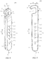
- Figs. 5 to 7 illustrate a second embodiment of the present disclosure.
- the difference between the second embodiment and the first embodiment is disclosed as follows.
- the outlet device 100 of the present embodiment further includes a limiting structure 5 movably disposed on the first case 12.
- the limiting structure 5 is arranged in the U-shaped hanging slot O for abutting against the plate 200.
- the following description discloses the features of the limiting structure 5, but the present disclosure is not limited thereto.
- the limiting structure 5 includes an abutting member 51 and an elastic member 52 (i.e., a torsion spring).
- An end of the abutting member 51 i.e., the bottom end of the abutting member 51 as shown in Fig. 6
- An opposite end of the abutting member 51 i.e., the top end of the abutting member 51 as shown in Fig. 6
- H a vertical distance
- a distance between the abutting member 51 and the first case 12 is gradually increased in a direction from bottom to top (i.e., a direction from right side to left side as shown in Fig. 6 ), and the vertical distance H is the maximum distance between the abutting member 51 and the first case 12.
- an accommodating slot 122 is recessed in an inner surface of the first case 12 (i.e., a surface of the first case 12 faces the second case 22) and is in air communication with the U-shaped hanging slot O.
- the accommodating slot 122 is configured to receive the limiting structure 5, and the abutting member 51 of the limiting structure 5 is movable toward (or movable into) the accommodating slot 122 when being pressed.
- the elastic member 52 stores an elastic force tending to recover the vertical distance H, so that the abutting member 51 can abut against the plate 200 by the elastic force generated from the elastic member 52.
- Figs. 8 to 12 illustrate a third embodiment of the present disclosure.
- the difference between the third embodiment and the first embodiment is disclosed as follows.
- the first case 12 having an elongated shape defines a longitudinal direction L, which is perpendicular to the lateral direction D and the width W.
- the first end of the third case 31 i.e., the bottom end of the third case 31 as shown in Figs. 8 and 9
- the second end of the third case 31 i.e., the top end of the third case 31 as shown in Figs. 8 and 9
- the connection of the first end of the third case 31 and the first case 12 in the present embodiment can be, but is not limited to, a rotatable connection as shown in Fig. 10 or a retractable connection as shown in Fig. 11 .
- the first outlet unit 11 includes a plurality of AC power outlets 111 arranged in one row parallel to the longitudinal direction L.
- the counterweight portion 1 has a switch unit 13 disposed on a bottom of the first case 12 for controlling the first outlet unit 11 and/or the second outlet unit 21 to supply electricity.
- the hanging portion 2 in the present embodiment is provided without any switch unit.
- the power cord 4 is connected to an end of the counterweight portion 1 (i.e., the bottom end of the first case 12 as shown in Fig. 9 ) arranged distant from the hanging portion 2.
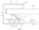
- Figs. 13 to 15 illustrate a fourth embodiment of the present disclosure.
- the difference between the fourth embodiment and the above embodiments is disclosed as follows.
- the outlet device 100 in the present embodiment can be provided with an outlet unit arranged on at least one of the counterweight portion 1 and the hanging portion 2.
- the figures of the present embodiment show the outlet unit 11 arranged on the counterweight portion 1, but the present disclosure is not limited thereto.
- the structures and the corresponding members of the counterweight portion 1, the hanging portion 2, and the extending portion 3 in the present disclosure can be interchanged or be adjusted according to designer demands.
- the outlet device 100 further includes a voice controlling module 6, and the voice controlling module 6 in the present embodiment is installed in the hanging portion 2 and is arranged outside the U-shaped hanging slot O, but the present disclosure is not limited thereto.
- the voice controlling module 6 can be installed in at least one of the counterweight portion 1, the hanging portion 2, and the extending portion 3.
- the voice controlling module 6 includes an AC/DC convertor 61, a voice receiver 62, a voice identifier 63, and a wireless controller 64.
- An end of the power cord 4 is connected to the counterweight portion 1 and is electrically connected to the outlet unit 11 and the AC/DC convertor 61, and the other end of the power cord 4 is used for detachably inserting into an external power supplying outlet 300.
- the power cord 4 can transmit electricity from the external power supplying outlet 300 to the outlet unit 11 and the AC/DC convertor 61.
- the power cord 4 can be omitted or can be replaced by other components (e.g., plug terminals).
- the outlet device 100 in the present embodiment is cooperated with (or includes) a plurality of expansion outlets 400, 400', and the voice controlling module 6 is wirelessly connected to the expansion outlets 400, 400' through a local area network (as shown in Fig. 13 ), an internet I (as shown in Fig. 14 ), or Bluetooth (not shown).
- a local area network as shown in Fig. 13
- an internet I as shown in Fig. 14
- Bluetooth not shown
- the AC/DC convertor 61 is electrically connected to the power cord 4, the voice receiver 62, the voice identifier 63, and the wireless controller 64, so that DC electricity converted by the AC/DC convertor 61 can be transmitted to the voice receiver 62, the voice identifier 63, and the wireless controller 64.
- the voice controlling module 6 in the present embodiment is provided with the AC/DC convertor 61, but the present disclosure is not limited thereto.
- the voice controlling module 6 and the DC power outlet can be provided to cooperate with the same AC/DC convertor, that is to say, the voice controlling module 6 can be cooperated with (i.e., electrically connected to) the AC/DC convertor of the outlet unit 11.
- the voice receiver 62 is installed to the second case 22, and the voice receiver 62 in the present embodiment is partially exposed from the second case 22 for clearly receiving a voice signal V (e.g., a user's dictation), but the present disclosure is not limited thereto.
- the voice receiver 62 can be arranged in the second case 22 entirely, and the second case 22 has at least one thru-hole corresponding in position to the voice receiver 62.
- the voice identifier 63 is electrically connected to the voice receiver 62 for identifying the voice signal V received from the voice receiver 62.
- the wireless controller 64 is electrically connected to the voice identifier 63 and is wirelessly connected to the expansion outlets 400, 400'.
- the voice identifier 63 is to identify the voice signal V received from the voice receiver 62, thereby opening or closing the expansion outlets 400, 400' by the wireless controller 64.
- each of the expansion outlets 400, 400' is provided for enabling at least one electronic device 500, 500' (e.g., a TV, an audio, or other household appliances) to insert thereinto, and the each of the expansion outlets 400, 400' can provide electricity for operating the corresponding electronic device 500, 500'.
- the voice receiver 62 receives a user's dictation (i.e., the voice signal V, such as: turn on or turn off)
- the voice identifier 63 is operated to identify the voice signal V and then transmits an identification result to the wireless controller 64, so that the wireless controller 64 will instruct the expansion outlets 400, 400' whether to supply electricity to the corresponding electronic devices 500, 500' or not according to the user's dictation. That is to say, the voice identifier 63 is to identify the voice signal V received from the voice receiver 62, thereby turning on or turning off the corresponding electronic devices 500, 500' by the wireless controller 64.
- the expansion outlets 400, 400' can be respectively identified according to different voice signals (not shown), and the voice identifier 63 is to distinguish the voice signals from each other.
- the voice identifier 63 is to identify the voice signal V received from the voice receiver 62, thereby opening or closing one of the expansion outlets 400, 400' corresponding to the received voice signal V by the wireless controller 64.
- the voice receiver 62 receives a user's dictation (i.e., the voice signal V, such as: opening the expansion outlet 400')
- the voice identifier 63 is operated to identify the voice signal V and then transmits an identification result to the wireless controller 64, so that the wireless controller 64 will instruct the expansion outlet 400' whether to supply electricity to the corresponding electronic device 500' or not according to the user's dictation.
- the outlet device 100 in the present embodiment can further include a speaker 7 installed on at least one of the hanging portion 2 and the extending portion 3 (i.e., Fig. 15 shows the speaker 7 installed on the hanging portion 2, but the present disclosure is not limited thereto).
- the speaker 7 is electrically connected to the AC/DC convertor 61 for receiving DC electricity from the AC/DC convertor 61.
- the speaker 7 is electrically connected to the voice controlling module 6 (i.e., the wireless controller 64) for being controlled by the voice controlling module 6.
- the voice controlling module 6 is configured to control volume of the speaker 7 according to the voice signal V received from the voice receiver 62.
- the voice receiver 62 receives a user's dictation (i.e., the voice signal V, such as: ramping volumes up, ramping volumes down, or mute)
- the voice identifier 63 is operated to identify the voice signal V and then transmits an identification result to the wireless controller 64, so that the wireless controller 64 will instruct the speaker 7 to ramp volumes up, to ramp volumes down, or to mute according to the user's dictation.
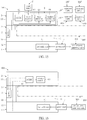
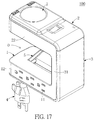
- Figs. 16 and 17 illustrate a fifth embodiment of the present disclosure.
- the difference between the fifth embodiment and the above embodiments is disclosed as follows.
- the outlet device 100 in the present embodiment does not include the voice controlling module 6 disclosed in the fourth embodiment. Specifically, the outlet device 100 of the present embodiment further includes a speaker 7, an AC/DC convertor 61, and a wireless controller 64 with respect to the outlet device 100 disclosed in the first to third embodiments.
- the speaker 7, the AC/DC convertor 61, and the wireless controller 64 can be installed to at least one of the counterweight portion 1, the hanging portion 2, and the extending portion 3, but the present disclosure is not limited thereto. As shown in Fig. 16 , the speaker 7 is installed on the third case 31 of the extending portion 3, and the AC/DC convertor 61 and the wireless controller 64 are installed in the hanging portion 2. Moreover, as shown in Fig. 17 , the speaker 7 is installed on the second case 22 of the hanging portion 2.
- the AC/DC convertor 61 is electrically connected to the power cord 4, the speaker 7, and the wireless controller 64, so that DC electricity converted by the AC/DC convertor 61 can be transmitted to the speaker 7 and the wireless controller 64.
- the outlet device 100 in the present embodiment is provided with the AC/DC convertor 61, but the present disclosure is not limited thereto. In other embodiments of the present disclosure, if the outlet unit 11 includes a DC power outlet and a corresponding AC/DC convertor, the outlet device 100 can use the AC/DC convertor of the outlet unit 11, so that the outlet device 100 can be provided without adding the AC/DC convertor 61.
- the speaker 7 is electrically connected to (i.e., wirelessly connected to) the wireless controller 64 for being controlled by the wireless controller 64.
- the wireless controller 64 is configured to control volume of the speaker 7 by receiving an external signal from an internet, a local area network, or Bluetooth.
- the outlet device of the first to third embodiments of the present disclosure can satisfy a condition where an outlet on the plate and an outlet under the plate are needed at the same time by disposing the hanging portion on the plate to provide the first outlet unit under the plate and the second outlet unit above the plate.
- the outlet device of the present disclosure can be firmly hung on a plate, which may have different thicknesses, by forming the limiting structure in the U-shaped hanging slot and using the limiting structure to abut against the plate.
- connection of the extending portion and the counterweight portion can be a movable connection, so that the outlet device of the present disclosure can be applied to different usage environments and can satisfy user needs.
- the outlet device of the fourth and fifth embodiments of the present disclosure is provided to wirelessly control an electronic device or a speaker (i.e., the electronic device is controlled by the voice controlling module, or the speaker is controlled by the wireless controller), thereby increasing the value added of the outlet device.
- the voice controlling module of the outlet device can be wirelessly connected to the expansion outlets through an internet or a local area network, such that a user can control the expansion outlets by speaking to the voice controlling module.
- the wireless controller of the outlet device can be used to control volume of the speaker, thereby further increasing the value added of the outlet device.
Landscapes
- Engineering & Computer Science (AREA)
- Microelectronics & Electronic Packaging (AREA)
- Physics & Mathematics (AREA)
- Health & Medical Sciences (AREA)
- Computational Linguistics (AREA)
- Audiology, Speech & Language Pathology (AREA)
- Human Computer Interaction (AREA)
- Acoustics & Sound (AREA)
- Multimedia (AREA)
- Structural Engineering (AREA)
- Architecture (AREA)
- Civil Engineering (AREA)
- Medical Informatics (AREA)
- Artificial Intelligence (AREA)
- Computer Vision & Pattern Recognition (AREA)
- Evolutionary Computation (AREA)
- Thermal Sciences (AREA)
- Software Systems (AREA)
- General Physics & Mathematics (AREA)
- Automation & Control Theory (AREA)
- Connector Housings Or Holding Contact Members (AREA)
- Details Of Connecting Devices For Male And Female Coupling (AREA)
- Disinfection, Sterilisation Or Deodorisation Of Air (AREA)
- Telephone Set Structure (AREA)
Applications Claiming Priority (1)
| Application Number | Priority Date | Filing Date | Title |
|---|---|---|---|
| TW105134550A TWI586051B (zh) | 2016-10-26 | 2016-10-26 | 掛吊式插座裝置 |
Publications (2)
| Publication Number | Publication Date |
|---|---|
| EP3316418A2 true EP3316418A2 (de) | 2018-05-02 |
| EP3316418A3 EP3316418A3 (de) | 2018-07-11 |
Family
ID=59688042
Family Applications (3)
| Application Number | Title | Priority Date | Filing Date |
|---|---|---|---|
| EP17189193.0A Active EP3316416B1 (de) | 2016-10-26 | 2017-09-04 | Mehrfachsteckdose |
| EP17198333.1A Withdrawn EP3316418A3 (de) | 2016-10-26 | 2017-10-25 | Auslassvorrichtung |
| EP17198306.7A Withdrawn EP3316417A1 (de) | 2016-10-26 | 2017-10-25 | Netzstecker |
Family Applications Before (1)
| Application Number | Title | Priority Date | Filing Date |
|---|---|---|---|
| EP17189193.0A Active EP3316416B1 (de) | 2016-10-26 | 2017-09-04 | Mehrfachsteckdose |
Family Applications After (1)
| Application Number | Title | Priority Date | Filing Date |
|---|---|---|---|
| EP17198306.7A Withdrawn EP3316417A1 (de) | 2016-10-26 | 2017-10-25 | Netzstecker |
Country Status (6)
| Country | Link |
|---|---|
| US (3) | US20180115125A1 (de) |
| EP (3) | EP3316416B1 (de) |
| JP (3) | JP6495982B2 (de) |
| CN (3) | CN107994387B (de) |
| AU (3) | AU2017216480B2 (de) |
| TW (1) | TWI586051B (de) |
Families Citing this family (33)
| Publication number | Priority date | Publication date | Assignee | Title |
|---|---|---|---|---|
| US10804660B2 (en) * | 2016-10-26 | 2020-10-13 | Powertech Industrial Co., Ltd. | Outlet device |
| US10996645B1 (en) | 2017-04-01 | 2021-05-04 | Smart Power Partners LLC | Modular power adapters and methods of implementing modular power adapters |
| US10530597B1 (en) | 2017-04-01 | 2020-01-07 | Smart Power Partners LLC | System for controlling a plurality of power switches configured to apply power to devices |
| US12093004B1 (en) | 2017-04-01 | 2024-09-17 | Smart Power Partners LLC | In-wall power adapter and method of implementing an in-wall power adapter |
| US10727731B1 (en) | 2017-04-01 | 2020-07-28 | Smart Power Partners, LLC | Power adapters adapted to receive a module and methods of implementing power adapters with modules |
| US12027968B2 (en) | 2017-04-01 | 2024-07-02 | John J. King | Power adapters and methods of implementing a power adapter |
| GB2577704A (en) * | 2018-10-03 | 2020-04-08 | Oxti Corp | Docking station for reducing desktop occupying space |
| EP3903640A4 (de) * | 2018-12-27 | 2022-08-03 | Schneider Electric España, S.A. | Tragbare stromversorgungs- und/oder dateneinheit |
| US10566746B1 (en) * | 2019-01-29 | 2020-02-18 | George Breeden | Illuminated electricity distribution device |
| US11189948B1 (en) | 2019-06-30 | 2021-11-30 | Smart Power Partners LLC | Power adapter and method of implementing a power adapter to provide power to a load |
| US10938168B2 (en) | 2019-06-30 | 2021-03-02 | Smart Power Partners LLC | In-wall power adapter and method of controlling the application of power to a load |
| US10965068B1 (en) | 2019-06-30 | 2021-03-30 | Smart Power Partners LLC | In-wall power adapter having an outlet and method of controlling an in-wall power adapter |
| US11990712B1 (en) | 2019-06-30 | 2024-05-21 | Smart Power Partners LLC | Control attachment for a power adapter and method of implementing a control attachment |
| US11579640B1 (en) | 2019-06-30 | 2023-02-14 | Smart Power Partners LLC | Control attachment for an in-wall power adapter |
| US11231730B1 (en) | 2019-06-30 | 2022-01-25 | Smart Power Power LLC | Control attachment for a power adapter configured to control power applied to a load |
| US10917956B1 (en) | 2019-06-30 | 2021-02-09 | Smart Power Partners LLC | Control attachment configured to provide power to a load and method of configuring a control attachment |
| US12045071B1 (en) | 2019-06-30 | 2024-07-23 | Smart Power Partners LLC | In-wall power adapter having an outlet |
| US11460874B1 (en) | 2019-06-30 | 2022-10-04 | Smart Power Partners LLC | In-wall power adapter configured to control the application of power to a load |
| US11201444B1 (en) | 2019-06-30 | 2021-12-14 | Smart Power Partners LLC | Power adapter having contact elements in a recess and method of controlling a power adapter |
| US12164350B1 (en) | 2019-06-30 | 2024-12-10 | Smart Power Partners LLC | Power adapter configured to provide power to a load |
| US10958020B1 (en) | 2019-06-30 | 2021-03-23 | Smart Power Partners LLC | Control attachment for an in-wall power adapter and method of controlling an in-wall power adapter |
| US11264769B1 (en) | 2019-06-30 | 2022-03-01 | Smart Power Partners LLC | Power adapter having contact elements in a recess and method of controlling a power adapter |
| US10958026B1 (en) | 2019-06-30 | 2021-03-23 | Smart Power Partners LLC | Contactless thermometer for an in-wall power adapter |
| US12066848B1 (en) | 2019-06-30 | 2024-08-20 | Smart Power Partners LLC | In-wall power adaper adapted to receive a control attachment and method of implementing a power adapter |
| US11043768B1 (en) | 2019-06-30 | 2021-06-22 | Smart Power Partners LLC | Power adapter configured to provide power to a load and method of implementing a power adapter |
| WO2021051337A1 (zh) * | 2019-09-19 | 2021-03-25 | 广东高普达集团股份有限公司 | 转接器 |
| KR102758924B1 (ko) * | 2020-01-06 | 2025-01-24 | 삼성전자주식회사 | 디스플레이 장치 |
| CN111491475B (zh) * | 2020-04-29 | 2021-06-01 | 广东电网有限责任公司东莞供电局 | 具有加热功能的电箱 |
| JP7557822B2 (ja) * | 2020-12-01 | 2024-09-30 | パナソニックIpマネジメント株式会社 | 配線システム、及び通信システム |
| US12015228B2 (en) * | 2021-09-17 | 2024-06-18 | Light Corp Inc. | Power receptacle assembly |
| US12300948B2 (en) | 2021-11-03 | 2025-05-13 | Smart Power Partners LLC | Control module having a control circuit and adapted to be attached to a power adapter |
| JP7756550B2 (ja) * | 2021-12-02 | 2025-10-20 | 株式会社Lixil | トイレ用リモコン装置 |
| CN119146585B (zh) * | 2024-11-15 | 2025-01-10 | 广州芬尼泳池设备科技有限公司 | 一种具有除锈防腐功能的泳池恒温热泵 |
Family Cites Families (77)
| Publication number | Priority date | Publication date | Assignee | Title |
|---|---|---|---|---|
| US2271463A (en) * | 1941-01-31 | 1942-01-27 | Ned S Reeves | Electric attachment for ironing boards, etc. |
| JPS6355382U (de) * | 1986-09-29 | 1988-04-13 | ||
| US4867701A (en) * | 1988-08-08 | 1989-09-19 | Wiand Richard K | Electrical outlet strip |
| US5086385A (en) * | 1989-01-31 | 1992-02-04 | Custom Command Systems | Expandable home automation system |
| JPH0963723A (ja) * | 1995-08-21 | 1997-03-07 | Matsushita Electric Works Ltd | 電源タップ |
| US6004157A (en) * | 1997-11-14 | 1999-12-21 | Virco Mfg. Corporation | Connector module |
| CN1233866A (zh) * | 1998-01-02 | 1999-11-03 | 蒙斯特电缆产品公司 | 通过带色标的中心电源为多个外围设备供电的装置和方法 |
| US6086397A (en) * | 1998-04-27 | 2000-07-11 | American Express Travel Related Services Company, Inc. | High reliability raised floor power strip |
| US6179665B1 (en) * | 1998-08-27 | 2001-01-30 | Curtis Computer Products, Inc. | Multi-function outlet strip having cable organizing features |
| CA2249000A1 (en) * | 1998-10-16 | 2000-04-16 | Hsien-Ting Huang | Voice-controlled electrical adapter |
| US6379182B1 (en) * | 1998-11-27 | 2002-04-30 | Norman R. Byrne | Energy center with interchangeable support bases |
| JP2001208384A (ja) * | 2000-01-26 | 2001-08-03 | Kokuyo Co Ltd | 喫煙用空気清浄装置 |
| US6540554B2 (en) * | 2001-02-27 | 2003-04-01 | Mccarthy David G. | Removably mountable receptacle unit |
| JP2003068375A (ja) * | 2001-08-28 | 2003-03-07 | Mitsumi Electric Co Ltd | 端子接続構造 |
| US6653562B2 (en) * | 2001-10-18 | 2003-11-25 | Pent Products, Inc. | Portable electrical unit |
| US20030092297A1 (en) * | 2001-11-12 | 2003-05-15 | Royal Appliance Mfg. Co. | Convenience light with supplemental electrical outlet |
| US20030176100A1 (en) * | 2002-02-07 | 2003-09-18 | Yurek John T. | Electrical device having a DC electrical outlet |
| US7139716B1 (en) * | 2002-08-09 | 2006-11-21 | Neil Gaziz | Electronic automation system |
| US20060072302A1 (en) * | 2004-10-01 | 2006-04-06 | Chien Tseng L | Electro-luminescent (EL) illuminated wall plate device with push-tighten frame means |
| US6642450B1 (en) * | 2002-12-06 | 2003-11-04 | Feng-Shen Hsiao | Wall outlet assembly |
| US7272008B2 (en) * | 2004-03-09 | 2007-09-18 | Intec, Inc. | Portable power inverter with pass through device |
| US7154402B2 (en) * | 2004-01-29 | 2006-12-26 | Michael Dayoub | Power strip with smoke detection auto-shutoff |
| US6971920B2 (en) * | 2004-04-26 | 2005-12-06 | Crupi Theodore P | Electrical multiple outlet device and electrical device having pivotable electrical prongs |
| EP1781341A1 (de) * | 2004-08-20 | 2007-05-09 | The Dial Corporation | Luftreiniger mit niedrigem profil |
| US9732921B2 (en) * | 2013-06-05 | 2017-08-15 | Tseng-Lu Chien | Multiple functions wall cover plate has built-in USB and light means |
| US7259567B2 (en) * | 2004-11-18 | 2007-08-21 | Harold Sears | Power tester for electrical outlets |
| US7358625B2 (en) * | 2004-12-14 | 2008-04-15 | Woods Industries, Inc. | Power strip with 12 volt outlet |
| US7083421B1 (en) * | 2005-05-25 | 2006-08-01 | Belkin Corporation | Electrical connectivity system capable of being mounted to an object, and method of manufacturing same |
| US7223122B2 (en) * | 2005-06-03 | 2007-05-29 | Belkin International, Inc. | Electrical connectivity system capable of being mounted to an object, and method of manufacturing same |
| US10333731B2 (en) * | 2005-06-09 | 2019-06-25 | Whirlpool Corporation | Methods and apparatus for communicatively coupling internal components within appliances, and appliances with external components and accessories |
| US8027752B2 (en) * | 2005-06-09 | 2011-09-27 | Whirlpool Corporation | Network for changing resource consumption in an appliance |
| WO2007082071A2 (en) * | 2006-01-11 | 2007-07-19 | Server Technology, Inc. | Power distribution unit and methods of making and use including modular construction and assemblies |
| US7734038B2 (en) * | 2006-05-01 | 2010-06-08 | Ortronics, Inc. | Electrical receptacle with open corner region |
| US7626119B2 (en) * | 2006-05-08 | 2009-12-01 | Axland Comec, Llc | Mountable power strips |
| CN101114185B (zh) * | 2006-07-26 | 2010-12-29 | 鸿富锦精密工业(深圳)有限公司 | 风流自动导向装置 |
| TW200830648A (en) * | 2007-01-03 | 2008-07-16 | Powertech Ind Ltd | Travel outlet device |
| JP3132822U (ja) * | 2007-04-06 | 2007-06-21 | 鎰勝工業股▲分▼有限公司 | 複合式延長線 |
| US7485804B2 (en) * | 2007-04-27 | 2009-02-03 | Thomas & Betts International, Inc. | Multi-media recess data low voltage box with slide-away hidden cover |
| US7938679B2 (en) * | 2007-07-31 | 2011-05-10 | Belkin International, Inc. | Electronic device or power strip with active clamping |
| US20090137163A1 (en) * | 2007-11-26 | 2009-05-28 | Optimal Innovations Inc. | Infrastructure device with modular replaceable sensors |
| US20090156061A1 (en) * | 2007-12-12 | 2009-06-18 | Charlie Bernstein | Non-linear power outlet expander and associated methods |
| US7795533B2 (en) * | 2008-07-03 | 2010-09-14 | Panduit Corp. | In-ceiling zone cabling enclosure |
| US8469748B2 (en) * | 2009-06-19 | 2013-06-25 | Benjamin Gerald Chambers | Coupler with universal adaptors for electricity, compressed air, fluids, and data |
| US8138430B1 (en) * | 2009-06-27 | 2012-03-20 | Jose Ucero | Window power distribution panel for exterior generator |
| JP2011040234A (ja) * | 2009-08-07 | 2011-02-24 | Panasonic Electric Works Co Ltd | 直流コンセント |
| US8016611B2 (en) * | 2009-09-25 | 2011-09-13 | Pucline Llc | Electrical power supplying device having a ring-like structure for receiving the power plugs and/or power adapters associated with a plurality of electrical appliances, and an integrated thermal management system |
| MX2009010902A (es) * | 2009-10-08 | 2011-04-20 | Magno Alcantara Talavera | Metodos y sistema de control por voz. |
| US20120028505A1 (en) * | 2010-07-29 | 2012-02-02 | Michael Weber | Power Strip with Articulatable Outlets |
| CN201732953U (zh) * | 2010-08-18 | 2011-02-02 | 上海理工大学 | 一种卡口式电源插座 |
| EP2448072B1 (de) * | 2010-10-26 | 2013-08-07 | Sedus Stoll AG | Medienleiste und Tisch |
| US8941976B1 (en) * | 2011-01-25 | 2015-01-27 | Western Digital Technologies, Inc. | Configurable powerline Ethernet adapter and power supply |
| BR112013021000A2 (pt) * | 2011-02-16 | 2016-10-11 | Kortek Ind Pty Ltd | controle de automação, energia sem fio e luz |
| TWI460576B (zh) * | 2011-05-04 | 2014-11-11 | Aopen Inc | 支架模組及具有該支架模組的電腦主機 |
| KR101213782B1 (ko) * | 2011-06-29 | 2012-12-18 | 백봉재 | 컴퓨터 연결 모듈 및 이를 구비한 책상 |
| US9462340B1 (en) * | 2011-10-13 | 2016-10-04 | Trevor Mathurin | Voice/manual activated and integrated audio/video multi-media, multi-interface system |
| US8920191B2 (en) * | 2012-01-10 | 2014-12-30 | Edison Nation, Llc | Clamp-on furniture electrical outlet |
| TWI456913B (zh) * | 2012-06-07 | 2014-10-11 | Askey Computer Corp | 具更換面板結構之電力線網路裝置 |
| US20140244267A1 (en) * | 2013-02-26 | 2014-08-28 | Avaya Inc. | Integration of user orientation into a voice command system |
| CN203180264U (zh) * | 2013-03-29 | 2013-09-04 | 公牛集团有限公司 | 移动插座链式固定机构 |
| US9679491B2 (en) * | 2013-05-24 | 2017-06-13 | Qualcomm Incorporated | Signaling device for teaching learning devices |
| US20140358553A1 (en) * | 2013-06-04 | 2014-12-04 | Richard John Helmke | Voice command for control of automation systems |
| US9614338B2 (en) * | 2013-06-07 | 2017-04-04 | Herman Miller, Inc. | Power module having multiple power receptacles |
| US20140376747A1 (en) * | 2013-06-20 | 2014-12-25 | Qmotion Incorporated | Voice control of lights and motorized window coverings |
| US20150005900A1 (en) * | 2013-06-26 | 2015-01-01 | Green Edge Technologies, Inc. | Devices and methods of function-based control in automation systems |
| US9298244B2 (en) * | 2013-09-30 | 2016-03-29 | Sonos, Inc. | Communication routes based on low power operation |
| US9543692B2 (en) * | 2013-10-29 | 2017-01-10 | American Iv, Inc. | Relocatable power tap for use in a patient care area |
| US9161464B2 (en) * | 2013-11-22 | 2015-10-13 | Sheng-Hsin Liao | Wall adaptor |
| US9698999B2 (en) * | 2013-12-02 | 2017-07-04 | Amazon Technologies, Inc. | Natural language control of secondary device |
| US20150281815A1 (en) * | 2014-03-31 | 2015-10-01 | Bose Corporation | Accessory Shelf |
| US9860076B2 (en) * | 2014-05-07 | 2018-01-02 | Vivint, Inc. | Home automation via voice control |
| CN204216362U (zh) * | 2014-11-28 | 2015-03-18 | 黄浩然 | 一种u型多功能插座 |
| US9766332B2 (en) * | 2014-12-11 | 2017-09-19 | Htc Corporation | Non-contact monitoring system and method thereof |
| TWI559632B (zh) * | 2015-01-05 | 2016-11-21 | 勝德國際研發股份有限公司 | 萬用插座 |
| CN105826766A (zh) * | 2015-01-08 | 2016-08-03 | 鸿富锦精密工业(武汉)有限公司 | 插座及语音识别方法 |
| US20160294127A1 (en) * | 2015-04-02 | 2016-10-06 | Susan Mouradian | Electrical Cable Storage Station |
| US9804652B2 (en) * | 2015-09-01 | 2017-10-31 | Humanscale Corporation | Computer docking station |
| US10433455B2 (en) * | 2016-03-30 | 2019-10-01 | Leviton Manufacturing Co., Inc. | Wiring device with heat removal system |
-
2016
- 2016-10-26 TW TW105134550A patent/TWI586051B/zh not_active IP Right Cessation
-
2017
- 2017-03-27 CN CN201710188315.7A patent/CN107994387B/zh not_active Expired - Fee Related
- 2017-06-02 US US15/612,614 patent/US20180115125A1/en not_active Abandoned
- 2017-08-16 AU AU2017216480A patent/AU2017216480B2/en not_active Ceased
- 2017-08-16 JP JP2017157103A patent/JP6495982B2/ja not_active Expired - Fee Related
- 2017-09-04 EP EP17189193.0A patent/EP3316416B1/de active Active
- 2017-10-16 CN CN201721332307.7U patent/CN207303552U/zh not_active Expired - Fee Related
- 2017-10-18 CN CN201721343783.9U patent/CN207490236U/zh not_active Expired - Fee Related
- 2017-10-25 EP EP17198333.1A patent/EP3316418A3/de not_active Withdrawn
- 2017-10-25 US US15/792,830 patent/US10381792B2/en not_active Expired - Fee Related
- 2017-10-25 EP EP17198306.7A patent/EP3316417A1/de not_active Withdrawn
- 2017-10-25 US US15/792,849 patent/US10312648B2/en not_active Expired - Fee Related
- 2017-10-26 AU AU2017251777A patent/AU2017251777B2/en not_active Ceased
- 2017-10-26 JP JP2017207218A patent/JP6505809B2/ja not_active Expired - Fee Related
- 2017-10-26 AU AU2017251778A patent/AU2017251778B2/en not_active Ceased
- 2017-10-26 JP JP2017207211A patent/JP6505808B2/ja not_active Expired - Fee Related
Non-Patent Citations (1)
| Title |
|---|
| None |
Also Published As
| Publication number | Publication date |
|---|---|
| CN207490236U (zh) | 2018-06-12 |
| JP6505809B2 (ja) | 2019-04-24 |
| CN107994387B (zh) | 2020-05-26 |
| US10381792B2 (en) | 2019-08-13 |
| CN207303552U (zh) | 2018-05-01 |
| CN107994387A (zh) | 2018-05-04 |
| AU2017216480B2 (en) | 2019-02-21 |
| US10312648B2 (en) | 2019-06-04 |
| EP3316416A2 (de) | 2018-05-02 |
| JP2018073831A (ja) | 2018-05-10 |
| AU2017251778A1 (en) | 2018-05-10 |
| TW201817099A (zh) | 2018-05-01 |
| US20180115125A1 (en) | 2018-04-26 |
| AU2017216480A1 (en) | 2018-05-10 |
| JP2018073807A (ja) | 2018-05-10 |
| AU2017251777A1 (en) | 2018-05-10 |
| US20180115108A1 (en) | 2018-04-26 |
| TWI586051B (zh) | 2017-06-01 |
| JP6495982B2 (ja) | 2019-04-03 |
| AU2017251777B2 (en) | 2019-02-14 |
| AU2017251778B2 (en) | 2019-02-14 |
| EP3316417A1 (de) | 2018-05-02 |
| JP6505808B2 (ja) | 2019-04-24 |
| EP3316416A3 (de) | 2018-06-27 |
| US20180115109A1 (en) | 2018-04-26 |
| EP3316418A3 (de) | 2018-07-11 |
| JP2018073832A (ja) | 2018-05-10 |
| EP3316416B1 (de) | 2019-05-22 |
Similar Documents
| Publication | Publication Date | Title |
|---|---|---|
| US10381792B2 (en) | Outlet device with voice control module having counterweight portion | |
| US20180109141A1 (en) | Wireless power stations | |
| CN108353478B (zh) | 插塞负载插座 | |
| WO2018100538A1 (en) | Low voltage dc electrical outlets | |
| KR20200061315A (ko) | 보조판을 구비한 거치대 | |
| AU2015100773A4 (en) | Dual combined socket and wireless charging apparatus | |
| CA2900389C (en) | Portable radio having accessory interface | |
| US20140220828A1 (en) | Signal connector module | |
| TWM607900U (zh) | 滑鼠組件 | |
| US10804660B2 (en) | Outlet device | |
| US20160104982A1 (en) | Connecting device for electronic appliance | |
| US20120083144A1 (en) | Power strip with safety cover | |
| US7285002B2 (en) | Electronic device assembly | |
| KR20160054917A (ko) | 무선 통신 기능을 구비한 멀티탭 | |
| CN104701663B (zh) | 排插组件 | |
| CN205122919U (zh) | 具有学习功能的插座控制器 | |
| JP6180989B2 (ja) | 電気機器の取付け具およびそれを用いた電気機器 | |
| CN212211388U (zh) | 一种除噪式分离型助听器主控盒组件 | |
| CN202145643U (zh) | 具有讯号模块的无线控制装置 | |
| WO2014067068A1 (zh) | 交换机外壳及具有交换机外壳的交换机 | |
| US20050218866A1 (en) | Apparatus for storing rechargers | |
| JP2021015927A (ja) | Acアダプタホルダ | |
| JP2016134925A (ja) | 可搬型ガス検知器の充電器 |
Legal Events
| Date | Code | Title | Description |
|---|---|---|---|
| PUAI | Public reference made under article 153(3) epc to a published international application that has entered the european phase |
Free format text: ORIGINAL CODE: 0009012 |
|
| STAA | Information on the status of an ep patent application or granted ep patent |
Free format text: STATUS: THE APPLICATION HAS BEEN PUBLISHED |
|
| AK | Designated contracting states |
Kind code of ref document: A2 Designated state(s): AL AT BE BG CH CY CZ DE DK EE ES FI FR GB GR HR HU IE IS IT LI LT LU LV MC MK MT NL NO PL PT RO RS SE SI SK SM TR |
|
| AX | Request for extension of the european patent |
Extension state: BA ME |
|
| PUAL | Search report despatched |
Free format text: ORIGINAL CODE: 0009013 |
|
| AK | Designated contracting states |
Kind code of ref document: A3 Designated state(s): AL AT BE BG CH CY CZ DE DK EE ES FI FR GB GR HR HU IE IS IT LI LT LU LV MC MK MT NL NO PL PT RO RS SE SI SK SM TR |
|
| AX | Request for extension of the european patent |
Extension state: BA ME |
|
| RIC1 | Information provided on ipc code assigned before grant |
Ipc: H01R 25/00 20060101AFI20180607BHEP Ipc: G10L 15/00 20130101ALI20180607BHEP Ipc: H01R 13/73 20060101ALI20180607BHEP Ipc: H01R 13/66 20060101ALI20180607BHEP |
|
| STAA | Information on the status of an ep patent application or granted ep patent |
Free format text: STATUS: REQUEST FOR EXAMINATION WAS MADE |
|
| 17P | Request for examination filed |
Effective date: 20181221 |
|
| RBV | Designated contracting states (corrected) |
Designated state(s): AL AT BE BG CH CY CZ DE DK EE ES FI FR GB GR HR HU IE IS IT LI LT LU LV MC MK MT NL NO PL PT RO RS SE SI SK SM TR |
|
| GRAP | Despatch of communication of intention to grant a patent |
Free format text: ORIGINAL CODE: EPIDOSNIGR1 |
|
| STAA | Information on the status of an ep patent application or granted ep patent |
Free format text: STATUS: GRANT OF PATENT IS INTENDED |
|
| RIC1 | Information provided on ipc code assigned before grant |
Ipc: H02G 3/18 20060101ALN20200319BHEP Ipc: H01R 13/66 20060101ALI20200319BHEP Ipc: G10L 15/22 20060101ALI20200319BHEP Ipc: H01R 13/73 20060101ALI20200319BHEP Ipc: H01R 25/00 20060101AFI20200319BHEP |
|
| INTG | Intention to grant announced |
Effective date: 20200403 |
|
| STAA | Information on the status of an ep patent application or granted ep patent |
Free format text: STATUS: THE APPLICATION IS DEEMED TO BE WITHDRAWN |
|
| 18D | Application deemed to be withdrawn |
Effective date: 20200814 |