EP3316432B1 - Dispositif d'alimentation électrique pourvu d'une interface permettant de faire fonctionner un système multitension - Google Patents
Dispositif d'alimentation électrique pourvu d'une interface permettant de faire fonctionner un système multitension Download PDFInfo
- Publication number
- EP3316432B1 EP3316432B1 EP17198307.5A EP17198307A EP3316432B1 EP 3316432 B1 EP3316432 B1 EP 3316432B1 EP 17198307 A EP17198307 A EP 17198307A EP 3316432 B1 EP3316432 B1 EP 3316432B1
- Authority
- EP
- European Patent Office
- Prior art keywords
- voltage
- network section
- power supply
- operating mode
- voltage source
- Prior art date
- Legal status (The legal status is an assumption and is not a legal conclusion. Google has not performed a legal analysis and makes no representation as to the accuracy of the status listed.)
- Active
Links
Images


Classifications
-
- B—PERFORMING OPERATIONS; TRANSPORTING
- B60—VEHICLES IN GENERAL
- B60L—PROPULSION OF ELECTRICALLY-PROPELLED VEHICLES; SUPPLYING ELECTRIC POWER FOR AUXILIARY EQUIPMENT OF ELECTRICALLY-PROPELLED VEHICLES; ELECTRODYNAMIC BRAKE SYSTEMS FOR VEHICLES IN GENERAL; MAGNETIC SUSPENSION OR LEVITATION FOR VEHICLES; MONITORING OPERATING VARIABLES OF ELECTRICALLY-PROPELLED VEHICLES; ELECTRIC SAFETY DEVICES FOR ELECTRICALLY-PROPELLED VEHICLES
- B60L50/00—Electric propulsion with power supplied within the vehicle
- B60L50/10—Electric propulsion with power supplied within the vehicle using propulsion power supplied by engine-driven generators, e.g. generators driven by combustion engines
- B60L50/15—Electric propulsion with power supplied within the vehicle using propulsion power supplied by engine-driven generators, e.g. generators driven by combustion engines with additional electric power supply
-
- A—HUMAN NECESSITIES
- A01—AGRICULTURE; FORESTRY; ANIMAL HUSBANDRY; HUNTING; TRAPPING; FISHING
- A01B—SOIL WORKING IN AGRICULTURE OR FORESTRY; PARTS, DETAILS, OR ACCESSORIES OF AGRICULTURAL MACHINES OR IMPLEMENTS, IN GENERAL
- A01B76/00—Parts, details or accessories of agricultural machines or implements, not provided for in groups A01B51/00 - A01B75/00
-
- B—PERFORMING OPERATIONS; TRANSPORTING
- B60—VEHICLES IN GENERAL
- B60L—PROPULSION OF ELECTRICALLY-PROPELLED VEHICLES; SUPPLYING ELECTRIC POWER FOR AUXILIARY EQUIPMENT OF ELECTRICALLY-PROPELLED VEHICLES; ELECTRODYNAMIC BRAKE SYSTEMS FOR VEHICLES IN GENERAL; MAGNETIC SUSPENSION OR LEVITATION FOR VEHICLES; MONITORING OPERATING VARIABLES OF ELECTRICALLY-PROPELLED VEHICLES; ELECTRIC SAFETY DEVICES FOR ELECTRICALLY-PROPELLED VEHICLES
- B60L1/00—Supplying electric power to auxiliary equipment of vehicles
-
- B—PERFORMING OPERATIONS; TRANSPORTING
- B60—VEHICLES IN GENERAL
- B60L—PROPULSION OF ELECTRICALLY-PROPELLED VEHICLES; SUPPLYING ELECTRIC POWER FOR AUXILIARY EQUIPMENT OF ELECTRICALLY-PROPELLED VEHICLES; ELECTRODYNAMIC BRAKE SYSTEMS FOR VEHICLES IN GENERAL; MAGNETIC SUSPENSION OR LEVITATION FOR VEHICLES; MONITORING OPERATING VARIABLES OF ELECTRICALLY-PROPELLED VEHICLES; ELECTRIC SAFETY DEVICES FOR ELECTRICALLY-PROPELLED VEHICLES
- B60L50/00—Electric propulsion with power supplied within the vehicle
- B60L50/50—Electric propulsion with power supplied within the vehicle using propulsion power supplied by batteries or fuel cells
- B60L50/60—Electric propulsion with power supplied within the vehicle using propulsion power supplied by batteries or fuel cells using power supplied by batteries
-
- B—PERFORMING OPERATIONS; TRANSPORTING
- B60—VEHICLES IN GENERAL
- B60R—VEHICLES, VEHICLE FITTINGS, OR VEHICLE PARTS, NOT OTHERWISE PROVIDED FOR
- B60R16/00—Electric or fluid circuits specially adapted for vehicles and not otherwise provided for; Arrangement of elements of electric or fluid circuits specially adapted for vehicles and not otherwise provided for
- B60R16/02—Electric or fluid circuits specially adapted for vehicles and not otherwise provided for; Arrangement of elements of electric or fluid circuits specially adapted for vehicles and not otherwise provided for electric constitutive elements
- B60R16/03—Electric or fluid circuits specially adapted for vehicles and not otherwise provided for; Arrangement of elements of electric or fluid circuits specially adapted for vehicles and not otherwise provided for electric constitutive elements for supply of electrical power to vehicle subsystems or for
-
- H—ELECTRICITY
- H02—GENERATION; CONVERSION OR DISTRIBUTION OF ELECTRIC POWER
- H02J—ELECTRIC POWER NETWORKS; CIRCUIT ARRANGEMENTS OR SYSTEMS FOR SUPPLYING OR DISTRIBUTING ELECTRIC POWER; SYSTEMS FOR STORING ELECTRIC ENERGY
- H02J1/00—Circuit arrangements for DC mains or DC distribution networks
- H02J1/08—Three-wire DC power distribution systems; Systems having more than three wires
- H02J1/082—DC supplies with two or more different DC voltage levels
-
- H—ELECTRICITY
- H02—GENERATION; CONVERSION OR DISTRIBUTION OF ELECTRIC POWER
- H02J—ELECTRIC POWER NETWORKS; CIRCUIT ARRANGEMENTS OR SYSTEMS FOR SUPPLYING OR DISTRIBUTING ELECTRIC POWER; SYSTEMS FOR STORING ELECTRIC ENERGY
- H02J7/00—Circuit arrangements for charging or discharging batteries or for supplying loads from batteries
- H02J7/14—Circuit arrangements for charging or discharging batteries or for supplying loads from batteries for charging batteries from dynamo-electric generators driven at varying speed, e.g. on vehicle
- H02J7/1423—Circuit arrangements for charging or discharging batteries or for supplying loads from batteries for charging batteries from dynamo-electric generators driven at varying speed, e.g. on vehicle with multiple batteries
-
- B—PERFORMING OPERATIONS; TRANSPORTING
- B60—VEHICLES IN GENERAL
- B60L—PROPULSION OF ELECTRICALLY-PROPELLED VEHICLES; SUPPLYING ELECTRIC POWER FOR AUXILIARY EQUIPMENT OF ELECTRICALLY-PROPELLED VEHICLES; ELECTRODYNAMIC BRAKE SYSTEMS FOR VEHICLES IN GENERAL; MAGNETIC SUSPENSION OR LEVITATION FOR VEHICLES; MONITORING OPERATING VARIABLES OF ELECTRICALLY-PROPELLED VEHICLES; ELECTRIC SAFETY DEVICES FOR ELECTRICALLY-PROPELLED VEHICLES
- B60L2200/00—Type of vehicles
- B60L2200/40—Working vehicles
-
- H—ELECTRICITY
- H02—GENERATION; CONVERSION OR DISTRIBUTION OF ELECTRIC POWER
- H02J—ELECTRIC POWER NETWORKS; CIRCUIT ARRANGEMENTS OR SYSTEMS FOR SUPPLYING OR DISTRIBUTING ELECTRIC POWER; SYSTEMS FOR STORING ELECTRIC ENERGY
- H02J2105/00—Networks for supplying or distributing electric power characterised by their spatial reach or by the load
- H02J2105/30—Networks for supplying or distributing electric power characterised by their spatial reach or by the load the load networks being external to vehicles, i.e. exchanging power with vehicles
-
- H—ELECTRICITY
- H02—GENERATION; CONVERSION OR DISTRIBUTION OF ELECTRIC POWER
- H02M—APPARATUS FOR CONVERSION BETWEEN AC AND AC, BETWEEN AC AND DC, OR BETWEEN DC AND DC, AND FOR USE WITH MAINS OR SIMILAR POWER SUPPLY SYSTEMS; CONVERSION OF DC OR AC INPUT POWER INTO SURGE OUTPUT POWER; CONTROL OR REGULATION THEREOF
- H02M3/00—Conversion of DC power input into DC power output
- H02M3/02—Conversion of DC power input into DC power output without intermediate conversion into AC
- H02M3/04—Conversion of DC power input into DC power output without intermediate conversion into AC by static converters
- H02M3/10—Conversion of DC power input into DC power output without intermediate conversion into AC by static converters using discharge tubes with control electrode or semiconductor devices with control electrode
- H02M3/145—Conversion of DC power input into DC power output without intermediate conversion into AC by static converters using discharge tubes with control electrode or semiconductor devices with control electrode using devices of a triode or transistor type requiring continuous application of a control signal
- H02M3/155—Conversion of DC power input into DC power output without intermediate conversion into AC by static converters using discharge tubes with control electrode or semiconductor devices with control electrode using devices of a triode or transistor type requiring continuous application of a control signal using semiconductor devices only
- H02M3/156—Conversion of DC power input into DC power output without intermediate conversion into AC by static converters using discharge tubes with control electrode or semiconductor devices with control electrode using devices of a triode or transistor type requiring continuous application of a control signal using semiconductor devices only with automatic control of output voltage or current, e.g. switching regulators
- H02M3/158—Conversion of DC power input into DC power output without intermediate conversion into AC by static converters using discharge tubes with control electrode or semiconductor devices with control electrode using devices of a triode or transistor type requiring continuous application of a control signal using semiconductor devices only with automatic control of output voltage or current, e.g. switching regulators including plural semiconductor devices as final control devices for a single load
-
- Y—GENERAL TAGGING OF NEW TECHNOLOGICAL DEVELOPMENTS; GENERAL TAGGING OF CROSS-SECTIONAL TECHNOLOGIES SPANNING OVER SEVERAL SECTIONS OF THE IPC; TECHNICAL SUBJECTS COVERED BY FORMER USPC CROSS-REFERENCE ART COLLECTIONS [XRACs] AND DIGESTS
- Y02—TECHNOLOGIES OR APPLICATIONS FOR MITIGATION OR ADAPTATION AGAINST CLIMATE CHANGE
- Y02T—CLIMATE CHANGE MITIGATION TECHNOLOGIES RELATED TO TRANSPORTATION
- Y02T10/00—Road transport of goods or passengers
- Y02T10/60—Other road transportation technologies with climate change mitigation effect
- Y02T10/70—Energy storage systems for electromobility, e.g. batteries
-
- Y—GENERAL TAGGING OF NEW TECHNOLOGICAL DEVELOPMENTS; GENERAL TAGGING OF CROSS-SECTIONAL TECHNOLOGIES SPANNING OVER SEVERAL SECTIONS OF THE IPC; TECHNICAL SUBJECTS COVERED BY FORMER USPC CROSS-REFERENCE ART COLLECTIONS [XRACs] AND DIGESTS
- Y02—TECHNOLOGIES OR APPLICATIONS FOR MITIGATION OR ADAPTATION AGAINST CLIMATE CHANGE
- Y02T—CLIMATE CHANGE MITIGATION TECHNOLOGIES RELATED TO TRANSPORTATION
- Y02T10/00—Road transport of goods or passengers
- Y02T10/60—Other road transportation technologies with climate change mitigation effect
- Y02T10/7072—Electromobility specific charging systems or methods for batteries, ultracapacitors, supercapacitors or double-layer capacitors
Definitions
- a dual voltage electrical system is also from the document DE 11 2012 007 029 T5 as known.
- the power supply arrangement for operating a multi-voltage system of an agricultural vehicle comprises a first network section with a motor generator connected to it and a second network section with a lead accumulator connected to it, the first network section having a first voltage level corresponding to the nominal voltage of the lead accumulator for operating electrical vehicle components and the second network section one thereof deviating, in contrast increased second voltage level for charging the lead accumulator and for supplying an electrical load comprised by an agricultural implement with electrical energy, wherein an interface is provided which forms a voltage source connecting the two network sections, which in charging mode one of the two Voltage levels provides resulting compensation voltage and which is bridged in an engine operating mode. Further features of the claimed arrangement are specified in claim 1.
- the motor generator is acted upon by the electrical energy available on the part of the lead accumulator in order to generate a corresponding drive torque, the operation of the electrical load being interrupted during this period.
- engine operation is prioritized over supplying the electrical load of the agricultural implement with electrical energy. Due to the bridging of the voltage source, the first and second network sections then have the same voltage level, namely the first voltage level.
- the first voltage level is preferably 48 volts and the second voltage level 56 volts, which results in a compensation voltage of 8 volts to be provided by the voltage source.
- the first voltage level is thus adapted to the use of standard components from the automotive or commercial vehicle sector, in particular according to the LV148 / VDA320 standard, whereas the second voltage level corresponds to the required charging voltage for lead batteries with a nominal voltage of 48 volts and the increased performance requirements of electrically operated agricultural implements justice.
- the motor generator is designed as a starter generator for starting an internal combustion engine connected to the drive.
- the motor generator is designed as a starter generator for starting an internal combustion engine connected to the drive.
- the use of a 48-volt electrical system enables high starting and cranking moments to be provided.
- a changeover switch for switching between the charging mode and the engine operating mode is provided, the second network section being connected to the voltage source in the charging mode and to the first network section in the engine operating mode. The second network section is then completely separated from the voltage source, so that it can remain switched on.
- the changeover switch can be structurally integrated into the voltage source in the form of an electromagnetic relay.
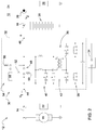
- the interface 30 for operating the multi-voltage system forms a voltage source 32 connecting the two network sections 14, 18.
- the voltage source 32 is a potential-free voltage converter 36 fed from an external voltage source 34.
- the voltage converter 36 comprises in addition to an in Fig. 1 schematically indicated inverters 38, 40 on the input and output sides an intermediate transformer 42.
- the lead accumulator 20 serves as the external voltage source 34.
- the first voltage level V 1 is thus adapted to the use of standard components from the automotive or commercial vehicle sector, in particular according to the LV148 / VDA320 standard, whereas the second voltage level V 2 corresponds to the required charging voltage for lead-acid batteries with a nominal voltage of 48 volts and the increased performance requirements electrically operated agricultural implements.
- the motor generator 16 is designed as a starter generator for starting an internal combustion engine connected to the drive. Especially in the case of powerful diesel engines with a large displacement, the use of a 48-volt electrical system enables high starting and cranking moments to be provided.
- Fig. 3 and 4th show a further power supply arrangement. This differs from the example described above with regard to the configuration of the voltage source 32.
Landscapes
- Engineering & Computer Science (AREA)
- Power Engineering (AREA)
- Mechanical Engineering (AREA)
- Transportation (AREA)
- Life Sciences & Earth Sciences (AREA)
- Sustainable Development (AREA)
- Sustainable Energy (AREA)
- Soil Sciences (AREA)
- Environmental Sciences (AREA)
- Control Of Charge By Means Of Generators (AREA)
- Charge And Discharge Circuits For Batteries Or The Like (AREA)
- Electric Propulsion And Braking For Vehicles (AREA)
Claims (10)
- Arrangement d'alimentation électrique destiné à faire fonctionner un système à tensions multiples d'un véhicule agricole, comprenant une première portion de réseau (14) à laquelle est raccordé un motogénérateur (16) et une deuxième portion de réseau (18) à laquelle est raccordé un accumulateur au plomb (20), la première portion de réseau (14) présentant un premier niveau de tension (V1) qui correspond à la tension nominale de l'accumulateur au plomb (20) et destiné à faire fonctionner des composants de véhicule (22) électriques, et la deuxième portion de réseau (18) présentant un deuxième niveau de tension (V2) différent de celui-ci, accru par rapport à celui-ci, destiné à charger l'accumulateur au plomb (20) ainsi qu'à alimenter en énergie électrique une charge électrique (26) comprise par un outil porté (24) agricole, une interface (30) étant présente, laquelle forme une source de tension (32) qui relie les deux portions de réseau (14, 18), laquelle fournit, dans un mode de fonctionnement de charge dans lequel le motogénérateur (16) est utilisé pour générer de l'énergie électrique, une tension d'équilibrage qui résulte des deux niveaux de tension (V1, V2) et laquelle, dans un mode de fonctionnement en moteur dans lequel le motogénérateur (16), en vue de générer un couple d'entraînement, est chargé avec l'énergie électrique disponible au niveau de l'accumulateur au plomb (20) en interrompant le fonctionnement de la charge électrique (26), est court-circuitée, un inverseur (62) destiné à permuter entre le mode de fonctionnement de charge et le mode de fonctionnement en moteur étant présent de telle sorte que la deuxième portion de réseau (18), en mode de fonctionnement de charge, est reliée à la source de tension (32) et, en mode de fonctionnement en moteur, est reliée à la première portion de réseau (14) avec séparation de la source de tension (32).
- Arrangement d'alimentation électrique selon la revendication 1, caractérisé en ce que le premier niveau de tension (V1) est de 48 volts et le deuxième niveau de tension (V2) est de 56 volts.
- Arrangement d'alimentation électrique selon la revendication 1 ou 2, caractérisé en ce que le motogénérateur (16) est réalisé sous la forme d'un générateur démarreur destiné à lancer un moteur à combustion interne relié en motricité à celui-ci.
- Arrangement d'alimentation électrique selon au moins l'une des revendications 1 à 3, caractérisé en ce que la source de tension (32) est un convertisseur de tension (36) exempt de potentiel alimenté à partir d'une source de tension externe (34).
- Arrangement d'alimentation électrique selon au moins l'une des revendications 1 à 3, caractérisé en ce que la source de tension (32) est un régulateur élévateur (60) branché en série avec la première et la deuxième portion de réseau (14, 18).
- Arrangement d'alimentation électrique selon au moins l'une des revendications 1 à 5, caractérisé en ce que le court-circuitage de la source de tension (32) est effectué au moyen d'un relais électromagnétique ou d'un commutateur semiconducteur.
- Arrangement d'alimentation électrique selon au moins l'une des revendications 1 à 6, caractérisé en ce que dans un mode de fonctionnement de précharge, qui précède le mode de fonctionnement en moteur, la source de tension (32) est court-circuitée au moyen d'un élément limiteur de courant pendant un temps de précharge prédéfini.
- Arrangement d'alimentation électrique selon au moins l'une des revendications 1 à 7, caractérisé en ce que l'accumulateur au plomb (20) possède une prise centrale (66) reliée à la première portion de réseau (14), laquelle se trouve entre les cellules individuelles de l'accumulateur au plomb (20).
- Arrangement d'alimentation électrique selon la revendication 8, caractérisé en ce qu'un double inverseur (68) destiné à permuter entre le mode de fonctionnement de charge et le mode de fonctionnement en moteur est présent de telle sorte que dans le mode de fonctionnement de charge, la première portion de réseau (14) est reliée au motogénérateur (16) et la deuxième portion de réseau est reliée (18) à la source de tension (32), et que dans le mode de fonctionnement en moteur, la deuxième portion de réseau (18) est reliée au motogénérateur (16) à la place de la première portion de réseau.
- Véhicule agricole, notamment tracteur agricole, comprenant un arrangement d'alimentation électrique (12) selon au moins l'une des revendications 1 à 9.
Applications Claiming Priority (1)
| Application Number | Priority Date | Filing Date | Title |
|---|---|---|---|
| DE102016221329.6A DE102016221329A1 (de) | 2016-10-28 | 2016-10-28 | Stromversorgungsanordnung mit einer Schnittstelle zum Betreiben eines Mehrspannungssystems |
Publications (2)
| Publication Number | Publication Date |
|---|---|
| EP3316432A1 EP3316432A1 (fr) | 2018-05-02 |
| EP3316432B1 true EP3316432B1 (fr) | 2020-07-29 |
Family
ID=60186085
Family Applications (1)
| Application Number | Title | Priority Date | Filing Date |
|---|---|---|---|
| EP17198307.5A Active EP3316432B1 (fr) | 2016-10-28 | 2017-10-25 | Dispositif d'alimentation électrique pourvu d'une interface permettant de faire fonctionner un système multitension |
Country Status (3)
| Country | Link |
|---|---|
| US (1) | US10821840B2 (fr) |
| EP (1) | EP3316432B1 (fr) |
| DE (1) | DE102016221329A1 (fr) |
Families Citing this family (3)
| Publication number | Priority date | Publication date | Assignee | Title |
|---|---|---|---|---|
| DE102019112706A1 (de) * | 2019-05-15 | 2020-11-19 | Bayerische Motoren Werke Aktiengesellschaft | Verfahren und Vorrichtung zur Energieversorgung eines elektrischen Verbrauchers eines Fahrzeugs |
| DE102021103954A1 (de) * | 2021-02-19 | 2022-08-25 | Bayerische Motoren Werke Aktiengesellschaft | Bordnetz und Verfahren zum Betrieb eines Bordnetzes |
| DE102022113617A1 (de) * | 2022-05-30 | 2023-11-30 | Rolls-Royce Solutions GmbH | Verfahren zum Betreiben eines Leistungsbereitstellungsnetzwerks, Steuervorrichtung zur Durchführung eines solchen Verfahrens und Leistungsbereitstellungsnetzwerk mit einer solchen Steuervorrichtung |
Family Cites Families (12)
| Publication number | Priority date | Publication date | Assignee | Title |
|---|---|---|---|---|
| DE10160266A1 (de) * | 2001-12-07 | 2003-06-18 | Daimler Chrysler Ag | Verfahren und Anordnung zur Ruhestromversorgung eines Fahrzeugs mit einem Mehrspannungsbordnetz |
| DE10231517B4 (de) * | 2002-07-12 | 2005-02-17 | Audi Ag | Bordnetz für ein Kraftfahrzeug |
| DE10251589A1 (de) * | 2002-11-06 | 2004-05-19 | Robert Bosch Gmbh | Bordnetz zur Versorgung mindestens eines Verbrauchers mit erhöhten Anforderungen an die Verfügbarkeit des Bordnetzes |
| DE10344563A1 (de) * | 2003-09-25 | 2005-04-28 | Bosch Gmbh Robert | Gleichspannungsbordnetz |
| DE102005051433B4 (de) * | 2005-10-27 | 2021-12-30 | Bayerische Motoren Werke Aktiengesellschaft | Verfahren und Vorrichtung zur Regelung eines Generators in einem Zwei-Spannungs-Bordnetz eines Kraftfahrzeuges |
| DE102012206932A1 (de) * | 2012-04-26 | 2013-10-31 | Robert Bosch Gmbh | Kraftfahrzeugbordnetz mit wenigstens zwei Teilnetzen |
| DE102012009738B4 (de) * | 2012-05-16 | 2017-10-05 | Audi Ag | Elektrische Schaltungsanordnung |
| WO2014061137A1 (fr) * | 2012-10-18 | 2014-04-24 | 三菱電機株式会社 | Système de gestion d'alimentation et procédé de gestion d'alimentation |
| DE102014104946A1 (de) * | 2014-04-08 | 2015-10-08 | Hella Kgaa Hueck & Co. | Schaltungsanordnung zur Stromversorgung |
| DE102015104293A1 (de) * | 2015-03-23 | 2016-09-29 | Hella Kgaa Hueck & Co. | Energiespeichervorrichtung |
| DE102015206366A1 (de) * | 2015-04-09 | 2016-10-13 | Deere & Company | Schnittstellenvorrichtung |
| DE102015106771A1 (de) * | 2015-04-30 | 2016-11-03 | Dr. Ing. H.C. F. Porsche Aktiengesellschaft | Batteriesystem |
-
2016
- 2016-10-28 DE DE102016221329.6A patent/DE102016221329A1/de not_active Withdrawn
-
2017
- 2017-10-25 EP EP17198307.5A patent/EP3316432B1/fr active Active
- 2017-10-26 US US15/794,461 patent/US10821840B2/en active Active
Non-Patent Citations (1)
| Title |
|---|
| None * |
Also Published As
| Publication number | Publication date |
|---|---|
| US10821840B2 (en) | 2020-11-03 |
| EP3316432A1 (fr) | 2018-05-02 |
| US20180118038A1 (en) | 2018-05-03 |
| DE102016221329A1 (de) | 2018-05-03 |
Similar Documents
| Publication | Publication Date | Title |
|---|---|---|
| EP3479455B1 (fr) | Dispositif à accumulateurs d'énergie pour véhicule automobile | |
| DE102008054885B4 (de) | Vorrichtung und Verfahren zum Steuern einer Energieversorgung eines Bordnetzes eines Fahrzeugs | |
| EP2501588B1 (fr) | Réseau de bord, méthode et dispositif de commande du réseau de bord | |
| EP1784910B1 (fr) | Regulateur de tension a protection contre les surtensions | |
| EP2516197A1 (fr) | Procédé et dispositif pour le déchargement d'un accumulateur d'énergie dans un réseau de haute tension | |
| DE102014008516A1 (de) | Bordnetz für ein Kraftfahrzeug | |
| DE102009024345A1 (de) | Schaltungsanordnung und Steuerverfahren zur Spannungsstützung eines Bordnetzes eines Fahrzeugs | |
| DE102011003764A1 (de) | Vorrichtung und Verfahren zur Entladung eines Energiespeichers in einem Hochvoltnetz | |
| EP2946965B1 (fr) | Dispositif et procédé de limitation du courant de démarrage lors du fonctionnement d'une charge capacitive sur un onduleur triphasé | |
| DE102012203467A1 (de) | Bordnetz für ein Fahrzeug | |
| DE102011012958A1 (de) | Energiespeichersystem mit einem Lithium-Ionen-Kondensator | |
| DE69813862T2 (de) | Verfahren und einrichtung zur ladesteuerung in einem elektrischen system mit zwei batterien | |
| EP3316432B1 (fr) | Dispositif d'alimentation électrique pourvu d'une interface permettant de faire fonctionner un système multitension | |
| EP3173280B1 (fr) | Batterie, véhicule comprenant une telle batterie et utilisation d'une telle batterie | |
| EP3720733B1 (fr) | Procédé de commande d'une installation électrique d'un véhicule à moteur à entraînement électrique, dotée de plusieurs batteries et installation électrique d'un véhicule à entraînement électrique | |
| EP1724158A2 (fr) | Réseau de bord de véhicule automobile avec une charge électrique de puissance élevée | |
| DE102009007545A1 (de) | Starthilfesystem | |
| WO2017220233A1 (fr) | Réseau électrique de bord de véhicule à moteur, doté d'au moins deux accumulateurs d'énergie, procédé pour faire fonctionner un réseau électrique de bord et moyens pour sa mise en oeuvre | |
| DE102010021402A1 (de) | Bordnetz für ein Kraftfahrzeug, Kraftfahrzeug und Verfahren zum Betreiben eines elektrischen Verbrauchers | |
| DE102007027482A1 (de) | Spannungsbegrenzungsschaltung | |
| DE102006037699B4 (de) | Spannungsversorgungseinrichtung für Nutzfahrzeuge | |
| DE102022204683A1 (de) | Niederspannungs-dc-dc-wandler eines umweltfreundlichen fahrzeugs und verfahren zum ausgeben einer konstanten spannung mittels desselben | |
| DE102018129592B4 (de) | Vorrichtung und Verfahren zum Bereitstellen elektrischer Energie in einem Fahrzeug | |
| DE102017212975A1 (de) | Schaltungsanordnung und Verfahren zum Betreiben eines Elektromotors | |
| WO2016180699A1 (fr) | Module de commutation de réseau de bord, dispositif d'assistance de réseau de bord et branche de réseau de bord |
Legal Events
| Date | Code | Title | Description |
|---|---|---|---|
| PUAI | Public reference made under article 153(3) epc to a published international application that has entered the european phase |
Free format text: ORIGINAL CODE: 0009012 |
|
| STAA | Information on the status of an ep patent application or granted ep patent |
Free format text: STATUS: THE APPLICATION HAS BEEN PUBLISHED |
|
| AK | Designated contracting states |
Kind code of ref document: A1 Designated state(s): AL AT BE BG CH CY CZ DE DK EE ES FI FR GB GR HR HU IE IS IT LI LT LU LV MC MK MT NL NO PL PT RO RS SE SI SK SM TR |
|
| AX | Request for extension of the european patent |
Extension state: BA ME |
|
| STAA | Information on the status of an ep patent application or granted ep patent |
Free format text: STATUS: REQUEST FOR EXAMINATION WAS MADE |
|
| 17P | Request for examination filed |
Effective date: 20181102 |
|
| RBV | Designated contracting states (corrected) |
Designated state(s): AL AT BE BG CH CY CZ DE DK EE ES FI FR GB GR HR HU IE IS IT LI LT LU LV MC MK MT NL NO PL PT RO RS SE SI SK SM TR |
|
| STAA | Information on the status of an ep patent application or granted ep patent |
Free format text: STATUS: EXAMINATION IS IN PROGRESS |
|
| 17Q | First examination report despatched |
Effective date: 20190226 |
|
| GRAP | Despatch of communication of intention to grant a patent |
Free format text: ORIGINAL CODE: EPIDOSNIGR1 |
|
| STAA | Information on the status of an ep patent application or granted ep patent |
Free format text: STATUS: GRANT OF PATENT IS INTENDED |
|
| RIC1 | Information provided on ipc code assigned before grant |
Ipc: B60L 50/50 20190101ALI20200123BHEP Ipc: B60L 50/15 20190101ALI20200123BHEP Ipc: B60R 16/03 20060101ALI20200123BHEP Ipc: H02J 1/00 20060101AFI20200123BHEP Ipc: H02J 7/14 20060101ALI20200123BHEP |
|
| INTG | Intention to grant announced |
Effective date: 20200220 |
|
| GRAS | Grant fee paid |
Free format text: ORIGINAL CODE: EPIDOSNIGR3 |
|
| GRAA | (expected) grant |
Free format text: ORIGINAL CODE: 0009210 |
|
| STAA | Information on the status of an ep patent application or granted ep patent |
Free format text: STATUS: THE PATENT HAS BEEN GRANTED |
|
| AK | Designated contracting states |
Kind code of ref document: B1 Designated state(s): AL AT BE BG CH CY CZ DE DK EE ES FI FR GB GR HR HU IE IS IT LI LT LU LV MC MK MT NL NO PL PT RO RS SE SI SK SM TR |
|
| REG | Reference to a national code |
Ref country code: CH Ref legal event code: EP |
|
| REG | Reference to a national code |
Ref country code: AT Ref legal event code: REF Ref document number: 1296916 Country of ref document: AT Kind code of ref document: T Effective date: 20200815 |
|
| REG | Reference to a national code |
Ref country code: IE Ref legal event code: FG4D Free format text: LANGUAGE OF EP DOCUMENT: GERMAN |
|
| REG | Reference to a national code |
Ref country code: DE Ref legal event code: R096 Ref document number: 502017006402 Country of ref document: DE |
|
| REG | Reference to a national code |
Ref country code: LT Ref legal event code: MG4D |
|
| REG | Reference to a national code |
Ref country code: NL Ref legal event code: MP Effective date: 20200729 |
|
| PG25 | Lapsed in a contracting state [announced via postgrant information from national office to epo] |
Ref country code: NO Free format text: LAPSE BECAUSE OF FAILURE TO SUBMIT A TRANSLATION OF THE DESCRIPTION OR TO PAY THE FEE WITHIN THE PRESCRIBED TIME-LIMIT Effective date: 20201029 Ref country code: ES Free format text: LAPSE BECAUSE OF FAILURE TO SUBMIT A TRANSLATION OF THE DESCRIPTION OR TO PAY THE FEE WITHIN THE PRESCRIBED TIME-LIMIT Effective date: 20200729 Ref country code: BG Free format text: LAPSE BECAUSE OF FAILURE TO SUBMIT A TRANSLATION OF THE DESCRIPTION OR TO PAY THE FEE WITHIN THE PRESCRIBED TIME-LIMIT Effective date: 20201029 Ref country code: SE Free format text: LAPSE BECAUSE OF FAILURE TO SUBMIT A TRANSLATION OF THE DESCRIPTION OR TO PAY THE FEE WITHIN THE PRESCRIBED TIME-LIMIT Effective date: 20200729 Ref country code: FI Free format text: LAPSE BECAUSE OF FAILURE TO SUBMIT A TRANSLATION OF THE DESCRIPTION OR TO PAY THE FEE WITHIN THE PRESCRIBED TIME-LIMIT Effective date: 20200729 Ref country code: PT Free format text: LAPSE BECAUSE OF FAILURE TO SUBMIT A TRANSLATION OF THE DESCRIPTION OR TO PAY THE FEE WITHIN THE PRESCRIBED TIME-LIMIT Effective date: 20201130 Ref country code: LT Free format text: LAPSE BECAUSE OF FAILURE TO SUBMIT A TRANSLATION OF THE DESCRIPTION OR TO PAY THE FEE WITHIN THE PRESCRIBED TIME-LIMIT Effective date: 20200729 Ref country code: HR Free format text: LAPSE BECAUSE OF FAILURE TO SUBMIT A TRANSLATION OF THE DESCRIPTION OR TO PAY THE FEE WITHIN THE PRESCRIBED TIME-LIMIT Effective date: 20200729 Ref country code: GR Free format text: LAPSE BECAUSE OF FAILURE TO SUBMIT A TRANSLATION OF THE DESCRIPTION OR TO PAY THE FEE WITHIN THE PRESCRIBED TIME-LIMIT Effective date: 20201030 |
|
| PG25 | Lapsed in a contracting state [announced via postgrant information from national office to epo] |
Ref country code: LV Free format text: LAPSE BECAUSE OF FAILURE TO SUBMIT A TRANSLATION OF THE DESCRIPTION OR TO PAY THE FEE WITHIN THE PRESCRIBED TIME-LIMIT Effective date: 20200729 Ref country code: PL Free format text: LAPSE BECAUSE OF FAILURE TO SUBMIT A TRANSLATION OF THE DESCRIPTION OR TO PAY THE FEE WITHIN THE PRESCRIBED TIME-LIMIT Effective date: 20200729 Ref country code: RS Free format text: LAPSE BECAUSE OF FAILURE TO SUBMIT A TRANSLATION OF THE DESCRIPTION OR TO PAY THE FEE WITHIN THE PRESCRIBED TIME-LIMIT Effective date: 20200729 Ref country code: IS Free format text: LAPSE BECAUSE OF FAILURE TO SUBMIT A TRANSLATION OF THE DESCRIPTION OR TO PAY THE FEE WITHIN THE PRESCRIBED TIME-LIMIT Effective date: 20201129 |
|
| PG25 | Lapsed in a contracting state [announced via postgrant information from national office to epo] |
Ref country code: NL Free format text: LAPSE BECAUSE OF FAILURE TO SUBMIT A TRANSLATION OF THE DESCRIPTION OR TO PAY THE FEE WITHIN THE PRESCRIBED TIME-LIMIT Effective date: 20200729 |
|
| PG25 | Lapsed in a contracting state [announced via postgrant information from national office to epo] |
Ref country code: DK Free format text: LAPSE BECAUSE OF FAILURE TO SUBMIT A TRANSLATION OF THE DESCRIPTION OR TO PAY THE FEE WITHIN THE PRESCRIBED TIME-LIMIT Effective date: 20200729 Ref country code: CZ Free format text: LAPSE BECAUSE OF FAILURE TO SUBMIT A TRANSLATION OF THE DESCRIPTION OR TO PAY THE FEE WITHIN THE PRESCRIBED TIME-LIMIT Effective date: 20200729 Ref country code: RO Free format text: LAPSE BECAUSE OF FAILURE TO SUBMIT A TRANSLATION OF THE DESCRIPTION OR TO PAY THE FEE WITHIN THE PRESCRIBED TIME-LIMIT Effective date: 20200729 Ref country code: SM Free format text: LAPSE BECAUSE OF FAILURE TO SUBMIT A TRANSLATION OF THE DESCRIPTION OR TO PAY THE FEE WITHIN THE PRESCRIBED TIME-LIMIT Effective date: 20200729 Ref country code: EE Free format text: LAPSE BECAUSE OF FAILURE TO SUBMIT A TRANSLATION OF THE DESCRIPTION OR TO PAY THE FEE WITHIN THE PRESCRIBED TIME-LIMIT Effective date: 20200729 |
|
| REG | Reference to a national code |
Ref country code: DE Ref legal event code: R097 Ref document number: 502017006402 Country of ref document: DE |
|
| PG25 | Lapsed in a contracting state [announced via postgrant information from national office to epo] |
Ref country code: AL Free format text: LAPSE BECAUSE OF FAILURE TO SUBMIT A TRANSLATION OF THE DESCRIPTION OR TO PAY THE FEE WITHIN THE PRESCRIBED TIME-LIMIT Effective date: 20200729 |
|
| REG | Reference to a national code |
Ref country code: CH Ref legal event code: PL |
|
| PLBE | No opposition filed within time limit |
Free format text: ORIGINAL CODE: 0009261 |
|
| STAA | Information on the status of an ep patent application or granted ep patent |
Free format text: STATUS: NO OPPOSITION FILED WITHIN TIME LIMIT |
|
| PG25 | Lapsed in a contracting state [announced via postgrant information from national office to epo] |
Ref country code: MC Free format text: LAPSE BECAUSE OF FAILURE TO SUBMIT A TRANSLATION OF THE DESCRIPTION OR TO PAY THE FEE WITHIN THE PRESCRIBED TIME-LIMIT Effective date: 20200729 Ref country code: LU Free format text: LAPSE BECAUSE OF NON-PAYMENT OF DUE FEES Effective date: 20201025 Ref country code: SK Free format text: LAPSE BECAUSE OF FAILURE TO SUBMIT A TRANSLATION OF THE DESCRIPTION OR TO PAY THE FEE WITHIN THE PRESCRIBED TIME-LIMIT Effective date: 20200729 |
|
| 26N | No opposition filed |
Effective date: 20210430 |
|
| REG | Reference to a national code |
Ref country code: BE Ref legal event code: MM Effective date: 20201031 |
|
| PG25 | Lapsed in a contracting state [announced via postgrant information from national office to epo] |
Ref country code: LI Free format text: LAPSE BECAUSE OF NON-PAYMENT OF DUE FEES Effective date: 20201031 Ref country code: SI Free format text: LAPSE BECAUSE OF FAILURE TO SUBMIT A TRANSLATION OF THE DESCRIPTION OR TO PAY THE FEE WITHIN THE PRESCRIBED TIME-LIMIT Effective date: 20200729 Ref country code: CH Free format text: LAPSE BECAUSE OF NON-PAYMENT OF DUE FEES Effective date: 20201031 Ref country code: BE Free format text: LAPSE BECAUSE OF NON-PAYMENT OF DUE FEES Effective date: 20201031 |
|
| PG25 | Lapsed in a contracting state [announced via postgrant information from national office to epo] |
Ref country code: IE Free format text: LAPSE BECAUSE OF NON-PAYMENT OF DUE FEES Effective date: 20201025 |
|
| PG25 | Lapsed in a contracting state [announced via postgrant information from national office to epo] |
Ref country code: TR Free format text: LAPSE BECAUSE OF FAILURE TO SUBMIT A TRANSLATION OF THE DESCRIPTION OR TO PAY THE FEE WITHIN THE PRESCRIBED TIME-LIMIT Effective date: 20200729 Ref country code: MT Free format text: LAPSE BECAUSE OF FAILURE TO SUBMIT A TRANSLATION OF THE DESCRIPTION OR TO PAY THE FEE WITHIN THE PRESCRIBED TIME-LIMIT Effective date: 20200729 Ref country code: CY Free format text: LAPSE BECAUSE OF FAILURE TO SUBMIT A TRANSLATION OF THE DESCRIPTION OR TO PAY THE FEE WITHIN THE PRESCRIBED TIME-LIMIT Effective date: 20200729 |
|
| PG25 | Lapsed in a contracting state [announced via postgrant information from national office to epo] |
Ref country code: MK Free format text: LAPSE BECAUSE OF FAILURE TO SUBMIT A TRANSLATION OF THE DESCRIPTION OR TO PAY THE FEE WITHIN THE PRESCRIBED TIME-LIMIT Effective date: 20200729 |
|
| REG | Reference to a national code |
Ref country code: AT Ref legal event code: MM01 Ref document number: 1296916 Country of ref document: AT Kind code of ref document: T Effective date: 20221025 |
|
| PG25 | Lapsed in a contracting state [announced via postgrant information from national office to epo] |
Ref country code: AT Free format text: LAPSE BECAUSE OF NON-PAYMENT OF DUE FEES Effective date: 20221025 |
|
| PGFP | Annual fee paid to national office [announced via postgrant information from national office to epo] |
Ref country code: DE Payment date: 20250919 Year of fee payment: 9 |
|
| PGFP | Annual fee paid to national office [announced via postgrant information from national office to epo] |
Ref country code: GB Payment date: 20251027 Year of fee payment: 9 |
|
| PGFP | Annual fee paid to national office [announced via postgrant information from national office to epo] |
Ref country code: IT Payment date: 20251021 Year of fee payment: 9 |
|
| PGFP | Annual fee paid to national office [announced via postgrant information from national office to epo] |
Ref country code: FR Payment date: 20251027 Year of fee payment: 9 |