EP3316452A1 - Elektrischer motor und elektrischer kompressor - Google Patents
Elektrischer motor und elektrischer kompressor Download PDFInfo
- Publication number
- EP3316452A1 EP3316452A1 EP17198064.2A EP17198064A EP3316452A1 EP 3316452 A1 EP3316452 A1 EP 3316452A1 EP 17198064 A EP17198064 A EP 17198064A EP 3316452 A1 EP3316452 A1 EP 3316452A1
- Authority
- EP
- European Patent Office
- Prior art keywords
- iron core
- axis
- magnet
- rotor
- electric
- Prior art date
- Legal status (The legal status is an assumption and is not a legal conclusion. Google has not performed a legal analysis and makes no representation as to the accuracy of the status listed.)
- Withdrawn
Links
- XEEYBQQBJWHFJM-UHFFFAOYSA-N Iron Chemical group [Fe] XEEYBQQBJWHFJM-UHFFFAOYSA-N 0.000 claims abstract description 105
- 229910000831 Steel Inorganic materials 0.000 claims abstract description 41
- 239000010959 steel Substances 0.000 claims abstract description 41
- 238000003780 insertion Methods 0.000 claims abstract description 39
- 230000037431 insertion Effects 0.000 claims abstract description 39
- 230000006835 compression Effects 0.000 claims description 18
- 238000007906 compression Methods 0.000 claims description 18
- 238000010030 laminating Methods 0.000 claims description 14
- 230000002093 peripheral effect Effects 0.000 claims description 14
- 239000003507 refrigerant Substances 0.000 description 9
- 230000007423 decrease Effects 0.000 description 8
- 230000004048 modification Effects 0.000 description 5
- 238000012986 modification Methods 0.000 description 5
- 239000012530 fluid Substances 0.000 description 3
- 238000003475 lamination Methods 0.000 description 2
- 238000004804 winding Methods 0.000 description 2
- 238000007792 addition Methods 0.000 description 1
- 230000015572 biosynthetic process Effects 0.000 description 1
- 238000005755 formation reaction Methods 0.000 description 1
- 229910052742 iron Inorganic materials 0.000 description 1
- 230000000149 penetrating effect Effects 0.000 description 1
- 238000006467 substitution reaction Methods 0.000 description 1
Images




Classifications
-
- H—ELECTRICITY
- H02—GENERATION; CONVERSION OR DISTRIBUTION OF ELECTRIC POWER
- H02K—DYNAMO-ELECTRIC MACHINES
- H02K1/00—Details of the magnetic circuit
- H02K1/06—Details of the magnetic circuit characterised by the shape, form or construction
- H02K1/22—Rotating parts of the magnetic circuit
- H02K1/27—Rotor cores with permanent magnets
- H02K1/2706—Inner rotors
- H02K1/272—Inner rotors the magnetisation axis of the magnets being perpendicular to the rotor axis
- H02K1/274—Inner rotors the magnetisation axis of the magnets being perpendicular to the rotor axis the rotor consisting of two or more circumferentially positioned magnets
- H02K1/2753—Inner rotors the magnetisation axis of the magnets being perpendicular to the rotor axis the rotor consisting of two or more circumferentially positioned magnets the rotor consisting of magnets or groups of magnets arranged with alternating polarity
- H02K1/276—Magnets embedded in the magnetic core, e.g. interior permanent magnets [IPM]
-
- H—ELECTRICITY
- H02—GENERATION; CONVERSION OR DISTRIBUTION OF ELECTRIC POWER
- H02K—DYNAMO-ELECTRIC MACHINES
- H02K7/00—Arrangements for handling mechanical energy structurally associated with dynamo-electric machines, e.g. structural association with mechanical driving motors or auxiliary dynamo-electric machines
- H02K7/04—Balancing means
-
- H—ELECTRICITY
- H02—GENERATION; CONVERSION OR DISTRIBUTION OF ELECTRIC POWER
- H02K—DYNAMO-ELECTRIC MACHINES
- H02K2201/00—Specific aspects not provided for in the other groups of this subclass relating to the magnetic circuits
- H02K2201/09—Magnetic cores comprising laminations characterised by being fastened by caulking
Definitions
- the present invention relates to an electric rotor and an electric compressor.
- a compressor for compressing a fluid such as a refrigerant gas is provided in an air conditioner, a refrigerator, or the like.
- an electric compressor is widely used, which includes a cylindrical case, an electric rotor (electric motor) which is accommodated in the case, and a compression mechanism which is driven by the electric rotor in the case (for example, refer to Patent Document 1).
- the electric rotor and the compression mechanism are accommodated to be sealed in the case, and a suction pipe for supplying a fluid such as a refrigerant gas to the compression mechanism through an accumulator or the like is connected to the compression mechanism.
- the electric motor includes a stator which is fixed to an inner peripheral surface of the case and a rotor (electric rotor) which is disposed inside the stator and supplies power to the stator to rotate around an axial center/axis.
- the stator is configured by winding a plurality of electric wires around a cylindrical core formed by laminating a plurality of thin magnetic steel plates through a plurality of slots provided at predetermined intervals therebetween in a circumferential direction of the cylindrical core.
- a coil end which is an end portion of a coil bundle, is provided on each of the upper end and the lower end of the stator.
- a rotor 100 includes an iron core 101 which is formed by laminating a plurality of thin magnetic steel plates, and a plurality of (for example, four, six, or the like) permanent magnets 102 are configured to be embedded in the iron core 101 in an axis O1 direction at predetermined intervals in a circumferential direction thereof.
- a plurality of permanent magnet insertion hole 103 are formed to penetrate the iron core 101 in the axis O1 direction at predetermined positions, and the permanent magnets 102 are inserted into the permanent magnet insertion hole 103 to be integrally embedded.
- a rotary shaft penetrates the rotor 100 at the center of the iron core 101 to be fixed, and an upper end plate 104 on an upper end of the iron core 101 and a lower end plate 105 on a lower end thereof are disposed to overlap the permanent magnet insertion holes 103 in the axis O1 direction in up and down direction.
- a counterweight (balance weight) 106 for suppressing runout of the rotor 100 when an electric motor is driven is attached to the upper end side or the lower end side of the iron core 101.
- Rivet holes 107 which extend in the axis O1 direction to communicate with each other are formed to penetrate the iron core 101, the upper end plate 104, the lower end plate 105, and the counterweight 106. Rivets 108 are disposed to be inserted into the rivet holes 107 and the upper end portions and the lower end portions of the rivets 108 are clinched so that the upper end plate 104, the lower end plate 105, and the counterweight 106 are pressed and fixed to the upper end side and the lower end side of the iron core 101.
- Patent Document 1 Japanese Unexamined Patent Application, First Publication No. 2009-240146
- an electric rotor including: an iron core which is formed by laminating a plurality of steel plates in an axis direction, the iron core being fixed to a rotary shaft such that axes of the iron core and the rotary shaft are coaxially disposed with each other; a plurality of magnets embedded in the iron core in a manner of being respectively inserted into a plurality of magnet insertion holes formed to penetrate the iron core along the axis; and rivets for integrally fixing at least the plurality of steel plates, the rivets being respectively inserted into a plurality of rivet holes formed to penetrate the iron core along the axis, in which the rivet includes a rivet body which is disposed to be inserted into the rivet hole and a pair of clinched portions which is formed by clinching opposite end portions thereof so that the plurality of steel plates are integrally pressed and fixed, and wherein the clinched portions are provided so as to overlap in the axis direction with the magnet inserted into the magnet insertion hole and are
- an electric rotor including: an iron core which is formed by laminating a plurality of steel plates in an axis direction, the iron core being fixed to a rotary shaft such that axes of the iron core and the rotary shaft are coaxially disposed with each other; a plurality of magnets embedded in the iron core in a manner of being respectively inserted into a plurality of magnet insertion holes formed to penetrate the iron core along the axis; a counterweight which is integrally provided in at least one of one end portion and the other end portion of the iron core in the axis direction; and rivets for integrally fixing the plurality of steel plates and the counterweight, the rivets being respectively inserted into a plurality of rivet holes formed to penetrate the iron core and the counterweight along the axis, in which the counterweight is provided so as to overlap in the axis direction with the magnet inserted into the magnet insertion hole and is configured such that the magnet is held by the counterweight.
- an electric rotor including: an iron core which is formed by laminating a plurality of steel plates in an axis direction, the iron core being fixed to a rotary shaft such that axes of the iron core and the rotary shaft are coaxially disposed with each other; a plurality of magnets embedded in the iron core in a manner of being respectively inserted into a plurality of magnet insertion holes formed to penetrate the iron core along the axis; rivets for integrally fixing at least the plurality of steel plates, the rivets being respectively inserted into a plurality of rivet holes formed to penetrate the iron core along the axis; and a counterweight which is integrally provided in at least one of one end portion and the other end portion of the iron core in the axis direction, wherein the rivet includes a rivet body which is disposed to be inserted into the rivet hole and a pair of clinched portions which is formed by clinching opposite end portions thereof so that the plurality of steel plates are integrally pressed and fixed
- an electric rotor including: an iron core which is formed by laminating a plurality of steel plates in an axis direction, the iron core being fixed to a rotary shaft such that axes of the iron core and the rotary shaft are coaxially disposed with each other; a plurality of magnets embedded in the iron core in a manner of being respectively inserted into a plurality of magnet insertion holes formed to penetrate the iron core along the axis, in which a hole for swaging is provided in at least one of one end portion and the other end portion of the iron core in the axis direction and in the vicinity of the magnet insertion hole, and wherein a swaged portion which presses the steel plate between the hole for swaging and the magnet inserted into the magnet insertion hole to the magnet so as to fix/hold the magnet is provided.
- an electric rotor including: an iron core which is formed by laminating a plurality of steel plates in an axis direction, the iron core being fixed to a rotary shaft such that axes of the iron core and the rotary shaft are coaxially disposed with each other; and a plurality of magnets embedded in the iron core in a manner of being respectively inserted into a plurality of magnet insertion holes formed to penetrate the iron core along the axis, in which an auto clamp formed by fitting recessed and projecting portions formed on the plurality of steel plates into each other is provided in the vicinity of the magnet insertion hole of the iron core, the auto clamp being collapsed and deformed by the pressurization to the iron core in the axis direction so as to provide a bulging portion pressing the magnet to fix/hold the magnet.
- an electric compressor including: an electric motor which is accommodated in a case; and a compression mechanism which is driven by the electric motor in the case, in which the electric motor includes a stator which is fixed to an inner peripheral surface of the case and an electric rotor which is disposed inside the stator, the electric rotor supplying power to the stator and rotating, and the electric rotor is any one of the above-described electric rotors.
- the electric rotor of the present invention and the electric compressor having this, it is possible to fix the magnet of the electric rotor in a state where the end plate of the related art is eliminated. Accordingly, the number of parts of the electric rotor and the electric motor is reduced, and it is possible to realize a decrease in a cost.
- FIGS. 1 to 5 an electric rotor and an electric compressor according to an embodiment of the present invention will be described with reference to FIGS. 1 to 5 .
- the electric compressor of the present embodiment is included in an air conditioner, a refrigerator, or the like to compress a fluid such as a refrigerant gas by driving of an electric motor.
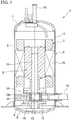
- an electric compressor 1 of the present embodiment is a sealed electric rotary compressor, and as shown in FIG. 1 , is configured to include a cylindrical case 2, an electric motor 3 which is accommodated in the case 2, and a compression mechanism 4 which is driven by the electric motor 3 in the case 2.
- the electric compressor 1 is incorporated in a refrigerant circuit including a condenser, an expansion valve, an evaporator, or the like, and compresses a refrigerant which flows through a pipe of the refrigerant circuit.
- the case 2 includes a tubular body 6, an upper cover 7 which is attached to an upper end of the body 6, and a lower cover 8 which is attached to a lower end of the body 6 and is configured such that the electric motor 3 and the compression mechanism 4 are accommodated in a sealed space inside the case 2.
- a suction pipe 10 through which a refrigerant gas is supplied to the compression mechanism 4 via an accumulator is connected to the body 6.
- the compression mechanism 4 includes a piston rotor 12 which is eccentrically attached to the other end portion opposite to one end portion of a rotary shaft 11, a cylinder 13 in which a piston rotor 12 is disposed, and an upper bearing 14 and a lower bearing 15 which rotatably support the rotary shaft 11 around an axial center (axis) O1.
- the compression mechanism 4 sequentially decreases or increases a volume of the compression chamber 16 formed inside the cylinder 13 according to a rotation of the piston rotor 12, and decreases the volume so as to compress a refrigerant gas.
- the piston rotor 12 has a shape which is eccentric to the axial center O1 of the rotary shaft 11 and is provided to be fitted to an outer periphery of the rotary shaft 11.
- the piston rotor 12 is inserted into an eccentric portion of the rotary shaft 11 between the upper bearing 14 and the lower bearing 15 and is provided to pivot around the axial center O1 of the rotary shaft 11.
- the cylinder 13 is provided such that a portion of an outer peripheral surface of the piston rotor 12 comes into sliding contact with a cylindrical inner peripheral surface of the cylinder 13.
- An axial center of an inner peripheral surface 13a of the cylinder 13 is disposed to be coaxial with the axial center O1 of the rotary shaft 11 and a space inside the inner peripheral surface 13a of the cylinder 13 is sealed by the upper bearing 14 and the lower bearing 15 to form the compression chamber 16.
- a slot 20 penetrating the cylinder 13 in the radial direction at one location in the circumferential direction is formed in the cylinder 13.
- a plate-shaped blade 21 is inserted into the slot 20.
- a base end of the blade 21 is pressed/urged inward in the radial direction by a coil spring 22.
- a tip of the blade 21 is always pressed to the outer peripheral surface of the piston rotor 12 by a pressing force caused by the coil spring 22 and a pressure caused by a compressed refrigerant inside the case 2, and thus, the blade 21 protrudes and retracts/moves forward or backward with respect to the inside of the cylinder 13 along the slot 20 in accordance with the piston rod 12.
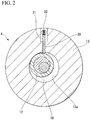
- the blade 21 is formed to have the same height as the dimension of the piston rotor 12 in the axial direction, and thus, as shown in FIG. 2 , the blade 21 divides the compression chamber 16 having a crescent-shaped cross section formed between the inner peripheral surface 13a of the cylinder 13 and the outer peripheral surface of the piston rotor 12 into two. Accordingly, the volumes of the two spaces divided by the blade 21 are proportionally distributed according to a rotation angle of the piston rotor 12.
- the electric motor 3 of the present embodiment is configured to include a stator 25 which is fixed to the inner peripheral surface of the case 2 and a rotor (electric rotor) A which is disposed inside the stator 25 and supplies power to the stator 25 to rotate.
- a coil end 17, which is an end portion of a coil bundle, is provided on each of the upper end and the lower end of the stator 25.
- the stator 25 is configured by winding a plurality of electric wires around a cylindrical core formed by laminating a plurality of thin magnetic steel plates through a plurality of slots provided at predetermined intervals therebetween in a circumferential direction of the cylindrical core.
- the rotor (electric rotor) A of the present embodiment includes an iron core 26 which is formed by laminating a plurality of thin magnetic steel plates.
- permanent magnets 27 (four permanent magnets 27 in the present embodiment) are each inserted into a plurality of (four in the present embodiment) magnet insertion holes 28 which are formed to penetrate the iron core 26 at predetermined intervals in a circumferential direction of the iron core 26, the permanent magnets 27 are embedded in the iron core 26 such that magnetic poles face the circumferential direction, and thus, the rotor A is configured.
- a rotary shaft 11 penetrates the center portion of the iron core 26 and is fixed to the iron core 26.
- rivets 30 are disposed to be inserted into rivet holes 29 formed to penetrate the iron core 26, and the upper end portions and the lower end portions of the rivets 30 are clinched to integrally fix the plurality of magnetic steel plates of the iron core 26.
- each rivet 30 includes a rivet body 30a which is inserted into the rivet hole 29 and a pair of clinched portions 30b which is formed on an upper end portion side and a lower end portion side of the rivet body 30a and presses and fixes an upper end portion side and a lower end portion side (one end portion side and the other end portion side in the axis O1 direction of the rotor A) of the iron core 26.
- At least a portion of the clinched portion 30b of the rivet 30 is provided to overlap the magnet insertion hole 28 and the permanent magnet 27 in the axis O1 direction so that the permanent magnet 27 abuts on the clinched portion 30b, and thus, the permanent magnet 27 is fixed/held.
- the permanent magnets 27 can be fixed/held by the clinched portions 30b of the rivets 30, and thus, it is possible to eliminate the end plates 104 and 105 for fixing the permanent magnets of the related art. Therefore, the number of parts of the electric rotor A, the electric motor 3, and the electric compressor 1 is reduced, and thus, it is possible to realize a decrease in a cost.
- the electric rotor A and the electric motor 3 are configured without providing a counterweight (balance weight) for suppressing runout of the rotor A when the electric motor 3 is driven.
- the counterweight may be provided.
- a plurality of through-holes which penetrate the electric rotor A of the electric motor 3 in the axis O1 direction to communicate with the compression chamber 16 may be formed, and thus, due to the formations of the plurality of through-holes, the runout of the rotor A is suppressed when the electric motor 3 is driven. That is, the through-holes may be provided in the iron core 26, and thus, a function similar to that of the counterweight which generates a centrifugal force in the same direction as a centrifugal force caused by the piston rotor 12 is exerted. In addition, the number of the laminated magnetic steel plates of the rotor A or the like may be adjusted to exert the function similar to that of the counterweight.
- the electric rotor A is included in the electric compressor 1 .
- the electric rotor A according to the present invention is not limited to be applied to the compressor 1.
- the electric rotor A is the four-electrode rotor (the rotor having four magnets 27).
- the electric rotor A may be a six-electrode rotor (a rotor having six magnets 27), and the number of the magnets 27 is not particularly limited.
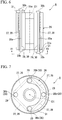
- FIGS. 6 and 7 FIGS. 1 and 2 .
- the electric rotor and the electric compressor according to the present invention are included in an air conditioner, a refrigerator, or the like. Accordingly, in the present embodiment, the same reference numerals are assigned to the configurations similar to those of the first embodiment, and detail descriptions thereof are omitted.
- the electric compressor 1/the electric motor 3 of the present embodiment are configured to include the stator 25 which is fixed to the inner peripheral surface of the case 2 and the rotor A which is disposed inside the stator 25 and supplies power to the stator 25 to rotate.
- a counterweight (balance weight) 31 for suppressing the runout of the rotor A when the electric motor 3 is driven is integrally attached to each of the upper end portion side and the lower end portion side of the iron core 26 at a predetermined position thereof.
- each counterweight 31 is integrally attached to the rotor A.
- each counterweight 31 pressed and fixed by the clinched portions 30b of the rivets 30 is provided to overlap the magnet insertion hole 28 and the permanent magnet 27 in the axis O1 direction. Accordingly, the permanent magnets 27 are fixed/held by abutting to the counterweight 31.
- the counterweights 31 are fixed at predetermined positions of the rotor A by the clinched portions 30b of the rivets 30, and it is possible to fix/hold the permanent magnets 27 by the counterweights 31. Accordingly, similarly to the first embodiment, it is possible to eliminate the end plates 104 and 105 for fixing the permanent magnets of the related art. Thereby, the number of parts of the electric rotor A, the electric motor 3, and the electric compressor 1 is reduced, and it is possible to realize a decrease in a cost.
- the present invention is not limited to the second embodiment, includes a modification example of the first embodiment, and can be appropriately modified within a scope which does not depart from the appended claims.
- the electric rotor A may be a six-electrode rotor (a rotor having six magnets 27), and the number of the magnets 27 is not particularly limited. In this way, in the case where the number of the magnets 27 increases or the like, it is considered that the runout of the rotor A when the electric motor 3 is driven can be reliably suppressed by appropriately and partially changing the shape and the thickness of the counterweight 31 provided on the upper end portion side or the lower end portion side.
- FIGS. 8 and 9 FIGS. 1 and 2 .
- the electric rotor and the compressor according to the present invention are included in an air conditioner, a refrigerator, or the like. Accordingly, in the present embodiment, the same reference numerals are assigned to the configurations similar to those of the first and second embodiments, and detail descriptions thereof are omitted.
- the electric compressor 1/the electric motor 3 of the present embodiment are configured to include the stator 25 which is fixed to the inner peripheral surface of the case 2 and the rotor A which is disposed inside the stator 25 and is rotated by supplying power to the stator 25.
- the rivets 30 are disposed to be inserted into the rivet holes 29 formed to penetrate the iron core 26, the upper end portions and the lower end portions of the rivets 30 are clinched, and the plurality of magnetic steel plates are formed to be integrally fixed.
- the holes 32 for swaging which extend in the axis O1 direction from the upper end portion and/or the lower end portion of the rotor A are provided on the upper end portion side and/or the lower end portion side of the rotor A.
- Each of the holes 32 for swaging is formed in the vicinity of each of the plurality of magnet insertion holes 28.
- the upper end portions and the lower end portions of the rivets 30 are clinched to integrally fix the plurality of magnetic steel plates.
- a swaging tool is inserted into the hole 32 for swaging to apply a swaging force to the magnetic steel plates of the iron core 26 from the hole 32 for swaging toward the permanent magnet 27 side in the vicinity of the hole 32 for swaging. Accordingly, the magnetic steel plates of the iron core 26 are deformed to be firmly fixed to the permanent magnet 27, and each permanent magnet 27 can be pressed and fixed by a swaged portion 33 of the magnetic steel plates.
- the holes 32 for swaging are provided in the rotor A, the swaging force is applied to the permanent magnets 27 from the iron core 26 using the holes 32 for swaging, and the respective permanent magnets 27 can be pressed and fixed. Accordingly, similarly to the first and second embodiments, it is possible to eliminate the end plates 104 and 105 for fixing the permanent magnets of the related art. Thereby, the number of parts of the electric rotor A, the electric motor 3, and the electric compressor 1 is reduced, and it is possible to realize a decrease in a cost.
- the present invention is not limited to the third embodiment, includes modification examples of the first and second embodiment, and can be appropriately modified within a scope which does not depart from the appended claims.
- the permanent magnets 27 may be fixed by appropriately and selectively combining the configurations of the present embodiment and the configurations of the first and second embodiments.
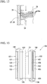
- FIGS. 10 to 12 FIGS. 1 and 2
- the electric rotor and the compressor according to the present invention are included in an air conditioner, a refrigerator, or the like. Accordingly, in the present embodiment, the same reference numerals are assigned to the configurations similar to those of the first to third embodiments, and detail descriptions thereof are omitted.
- the electric compressor 1/the electric motor 3 of the present embodiment are configured to include the stator 25 and the rotor A.
- embossed portions (hereinafter, referred to as "auto clamps") 34 are provided in the vicinities of the magnet insertion holes 28 of the lower end portion side (and/or the upper end portion side) of the iron core 26. That is, thin magnetic steel plates 26a to which the auto clamps 34 formed to be uneven in the vicinities of the magnet insertion holes 28 are embossed are used on the lower end portion side (and/or the upper end portion side) of the iron core 26.
- embossed protrusions are fitted to be pressurized to recessed portions on the rear surface of the protrusions in the thin magnetic steel plates 26a of adjacent layers to overlap each other. Accordingly, upper and lower steel plates 26a are fixed to each other to be laminated to have a predetermined thickness, and thus, the iron core 26 and the rotor A are formed.
- the iron core 26 is again pressurized in the lamination direction by a re-pressurization force which is larger than the pressure when the iron core 26 is fixed to be laminated, by the plurality of auto clamps 34.
- the auto clamps 34 are provided in the vicinities of the magnet insertion holes 28, the auto clamps 34 are deeply fitted to each other by the re-pressurization force, and bulging portions 35 are generated over the entire region in the lamination direction on the wall surfaces of the magnet insertion holes 28 positioned in the iron core 26 in the vicinities of the auto clamps 34.
- the permanent magnets 27 are pressed by the bulging portions 35 and thus, the permanent magnets 27 are pressed and fixed into the magnet insertion holes 28.
- the electric rotor A and the electric compressor 1 of the present embodiment the permanent magnets 27 are pressed and fixed by the auto clamps (auto clamp mechanism) 34. Therefore, it is possible to eliminate the end plates 104 and 105 for fixing the permanent magnets of the related art. Thereby, the number of parts of the electric rotor A, the electric motor 3, and the electric compressor 1 is reduced, and it is possible to realize a decrease in a cost.
- the fourth embodiment of the electric rotor and the electric compressor according to the present invention is described.
- the present invention is not limited to the fourth embodiment, includes modification examples of the first to third embodiments, and can be appropriately modified within a scope which does not depart from the appended claims.
- the permanent magnets 27 may be fixed by appropriately and selectively combining the configurations of the present embodiment and the configurations of the first to third embodiments.
Landscapes
- Engineering & Computer Science (AREA)
- Power Engineering (AREA)
- Permanent Field Magnets Of Synchronous Machinery (AREA)
- Iron Core Of Rotating Electric Machines (AREA)
- Compressor (AREA)
- Applications Or Details Of Rotary Compressors (AREA)
- Connection Of Motors, Electrical Generators, Mechanical Devices, And The Like (AREA)
Applications Claiming Priority (1)
| Application Number | Priority Date | Filing Date | Title |
|---|---|---|---|
| JP2016210860A JP6465496B2 (ja) | 2016-10-27 | 2016-10-27 | 電動ロータ及び電動圧縮機 |
Publications (1)
| Publication Number | Publication Date |
|---|---|
| EP3316452A1 true EP3316452A1 (de) | 2018-05-02 |
Family
ID=60162144
Family Applications (1)
| Application Number | Title | Priority Date | Filing Date |
|---|---|---|---|
| EP17198064.2A Withdrawn EP3316452A1 (de) | 2016-10-27 | 2017-10-24 | Elektrischer motor und elektrischer kompressor |
Country Status (2)
| Country | Link |
|---|---|
| EP (1) | EP3316452A1 (de) |
| JP (1) | JP6465496B2 (de) |
Cited By (2)
| Publication number | Priority date | Publication date | Assignee | Title |
|---|---|---|---|---|
| CN110858734A (zh) * | 2018-08-20 | 2020-03-03 | 无锡小天鹅电器有限公司 | 转子、电机及洗衣机 |
| CN113765248A (zh) * | 2020-06-03 | 2021-12-07 | Weg电力设备公司 | 旋转电机的转子、制造工艺方法以及对应的旋转电机 |
Citations (6)
| Publication number | Priority date | Publication date | Assignee | Title |
|---|---|---|---|---|
| EP0538472A1 (de) * | 1990-07-12 | 1993-04-28 | Seiko Epson Corporation | Läufer eines bürstenlosen motors und herstellung desselben |
| JP2009240146A (ja) | 2008-03-05 | 2009-10-15 | Panasonic Corp | ブラシレスdcモータの回転子、この回転子を備えた圧縮機、およびこの圧縮機を搭載した機器 |
| JP2010246390A (ja) * | 2010-07-21 | 2010-10-28 | Daikin Ind Ltd | モータ回転子 |
| EP2270954A2 (de) * | 2009-06-30 | 2011-01-05 | Sanyo Electric Co., Ltd. | Rotor eines Elektromotors |
| JP2012244649A (ja) * | 2011-05-16 | 2012-12-10 | Daikin Ind Ltd | 回転子および回転電機 |
| US20160238105A1 (en) * | 2015-02-18 | 2016-08-18 | Nidec Motor Corporation | Traction motor assembly with gear-interconnected wheel and output shaft |
Family Cites Families (6)
| Publication number | Priority date | Publication date | Assignee | Title |
|---|---|---|---|---|
| JPS52129957U (de) * | 1976-03-30 | 1977-10-03 | ||
| JPS52129958U (de) * | 1976-03-30 | 1977-10-03 | ||
| JP2003143786A (ja) * | 2001-11-01 | 2003-05-16 | Mitsubishi Electric Corp | 永久磁石式回転子及びその製造方法 |
| JP2007040139A (ja) * | 2005-08-02 | 2007-02-15 | Matsushita Electric Ind Co Ltd | 圧縮機 |
| JP2012050226A (ja) * | 2010-08-26 | 2012-03-08 | Fuji Electric Co Ltd | 永久磁石形回転電機の回転子 |
| JP2013211989A (ja) * | 2012-03-30 | 2013-10-10 | Toyota Industries Corp | 永久磁石埋め込み型モータ、及び、それを備えた電動コンプレッサ |
-
2016
- 2016-10-27 JP JP2016210860A patent/JP6465496B2/ja active Active
-
2017
- 2017-10-24 EP EP17198064.2A patent/EP3316452A1/de not_active Withdrawn
Patent Citations (6)
| Publication number | Priority date | Publication date | Assignee | Title |
|---|---|---|---|---|
| EP0538472A1 (de) * | 1990-07-12 | 1993-04-28 | Seiko Epson Corporation | Läufer eines bürstenlosen motors und herstellung desselben |
| JP2009240146A (ja) | 2008-03-05 | 2009-10-15 | Panasonic Corp | ブラシレスdcモータの回転子、この回転子を備えた圧縮機、およびこの圧縮機を搭載した機器 |
| EP2270954A2 (de) * | 2009-06-30 | 2011-01-05 | Sanyo Electric Co., Ltd. | Rotor eines Elektromotors |
| JP2010246390A (ja) * | 2010-07-21 | 2010-10-28 | Daikin Ind Ltd | モータ回転子 |
| JP2012244649A (ja) * | 2011-05-16 | 2012-12-10 | Daikin Ind Ltd | 回転子および回転電機 |
| US20160238105A1 (en) * | 2015-02-18 | 2016-08-18 | Nidec Motor Corporation | Traction motor assembly with gear-interconnected wheel and output shaft |
Cited By (4)
| Publication number | Priority date | Publication date | Assignee | Title |
|---|---|---|---|---|
| CN110858734A (zh) * | 2018-08-20 | 2020-03-03 | 无锡小天鹅电器有限公司 | 转子、电机及洗衣机 |
| CN113765248A (zh) * | 2020-06-03 | 2021-12-07 | Weg电力设备公司 | 旋转电机的转子、制造工艺方法以及对应的旋转电机 |
| US20210384797A1 (en) * | 2020-06-03 | 2021-12-09 | Weg Equipamentos Eletricos S.A. | Rotor for rotary electric machine, process for manufacturing and corresponding rotary electric machines |
| US11979078B2 (en) * | 2020-06-03 | 2024-05-07 | Weg Equipamentos Eletricos S.A. | Rotor for rotary electric machine, process for manufacturing and corresponding rotary electric machines |
Also Published As
| Publication number | Publication date |
|---|---|
| JP6465496B2 (ja) | 2019-02-06 |
| JP2018074715A (ja) | 2018-05-10 |
Similar Documents
| Publication | Publication Date | Title |
|---|---|---|
| EP3597921A1 (de) | Verdichter | |
| EP2749735A2 (de) | Verdichter | |
| CN107431394A (zh) | 压缩机用永久磁铁埋入型电动机、压缩机以及制冷循环装置 | |
| CN104641115B (zh) | 回转式压缩机 | |
| EP3316452A1 (de) | Elektrischer motor und elektrischer kompressor | |
| US20170284396A1 (en) | Electric compressor | |
| EP2385255A2 (de) | Hermetischer Kompressor und Herstellungsverfahren dafür | |
| JP2007177624A (ja) | 2気筒回転式密閉型圧縮機及び2気筒回転式密閉型圧縮機の製造方法 | |
| US20170284395A1 (en) | Electric compressor | |
| KR100675549B1 (ko) | 전동 콤프레서 | |
| CN111033953B (zh) | 定子、具备该定子的马达、具备该马达的压缩机以及具备该压缩机的空调机 | |
| EP3337014A2 (de) | Rotor eines elektromotors und kompressors | |
| CN108700052A (zh) | 气液分离器固定用具、密闭型压缩机、密闭型压缩机的制造装置及密闭型压缩机的制造方法 | |
| EP1793469A1 (de) | Synchron-Reluktanzmotor und Verdichter damit | |
| KR102018472B1 (ko) | 고정자 철심, 압축기 및 냉동 사이클 장치 | |
| JP6151324B2 (ja) | 密閉型電動圧縮機 | |
| KR102191953B1 (ko) | 전동 압축기 | |
| US20160281717A1 (en) | Rotary compressor | |
| JP2014109204A (ja) | 圧縮機 | |
| EP2749736B1 (de) | Verdichter | |
| EP2942526A1 (de) | Rotationsverdichter | |
| WO2020208777A1 (ja) | 圧縮機、及び、圧縮機用電動機 | |
| JP3718027B2 (ja) | ロータリ式圧縮機 | |
| US9964122B2 (en) | Compressor staking arrangement and method | |
| EP3311933B1 (de) | Verstemmwerkzeug, herstellungsverfahren für eine verstemmungsstruktur und herstellungsverfahren für einen kompressor |
Legal Events
| Date | Code | Title | Description |
|---|---|---|---|
| PUAI | Public reference made under article 153(3) epc to a published international application that has entered the european phase |
Free format text: ORIGINAL CODE: 0009012 |
|
| STAA | Information on the status of an ep patent application or granted ep patent |
Free format text: STATUS: THE APPLICATION HAS BEEN PUBLISHED |
|
| AK | Designated contracting states |
Kind code of ref document: A1 Designated state(s): AL AT BE BG CH CY CZ DE DK EE ES FI FR GB GR HR HU IE IS IT LI LT LU LV MC MK MT NL NO PL PT RO RS SE SI SK SM TR |
|
| AX | Request for extension of the european patent |
Extension state: BA ME |
|
| STAA | Information on the status of an ep patent application or granted ep patent |
Free format text: STATUS: REQUEST FOR EXAMINATION WAS MADE |
|
| 17P | Request for examination filed |
Effective date: 20181102 |
|
| RBV | Designated contracting states (corrected) |
Designated state(s): AL AT BE BG CH CY CZ DE DK EE ES FI FR GB GR HR HU IE IS IT LI LT LU LV MC MK MT NL NO PL PT RO RS SE SI SK SM TR |
|
| STAA | Information on the status of an ep patent application or granted ep patent |
Free format text: STATUS: EXAMINATION IS IN PROGRESS |
|
| 17Q | First examination report despatched |
Effective date: 20190125 |
|
| STAA | Information on the status of an ep patent application or granted ep patent |
Free format text: STATUS: THE APPLICATION IS DEEMED TO BE WITHDRAWN |
|
| 18D | Application deemed to be withdrawn |
Effective date: 20191109 |