EP3316455A1 - Motor, waschpumpe, geschirrspüler und herstellungsverfahren - Google Patents
Motor, waschpumpe, geschirrspüler und herstellungsverfahren Download PDFInfo
- Publication number
- EP3316455A1 EP3316455A1 EP15896644.0A EP15896644A EP3316455A1 EP 3316455 A1 EP3316455 A1 EP 3316455A1 EP 15896644 A EP15896644 A EP 15896644A EP 3316455 A1 EP3316455 A1 EP 3316455A1
- Authority
- EP
- European Patent Office
- Prior art keywords
- injection
- molded
- electric motor
- enveloping portion
- stator
- Prior art date
- Legal status (The legal status is an assumption and is not a legal conclusion. Google has not performed a legal analysis and makes no representation as to the accuracy of the status listed.)
- Withdrawn
Links
Images




Classifications
-
- H—ELECTRICITY
- H02—GENERATION; CONVERSION OR DISTRIBUTION OF ELECTRIC POWER
- H02K—DYNAMO-ELECTRIC MACHINES
- H02K17/00—Asynchronous induction motors; Asynchronous induction generators
- H02K17/02—Asynchronous induction motors
- H02K17/04—Asynchronous induction motors for single phase current
- H02K17/08—Motors with auxiliary phase obtained by externally fed auxiliary windings, e.g. capacitor motors
-
- H—ELECTRICITY
- H02—GENERATION; CONVERSION OR DISTRIBUTION OF ELECTRIC POWER
- H02K—DYNAMO-ELECTRIC MACHINES
- H02K5/00—Casings; Enclosures; Supports
- H02K5/04—Casings or enclosures characterised by the shape, form or construction thereof
- H02K5/12—Casings or enclosures characterised by the shape, form or construction thereof specially adapted for operating in liquid or gas
-
- H—ELECTRICITY
- H02—GENERATION; CONVERSION OR DISTRIBUTION OF ELECTRIC POWER
- H02K—DYNAMO-ELECTRIC MACHINES
- H02K5/00—Casings; Enclosures; Supports
- H02K5/04—Casings or enclosures characterised by the shape, form or construction thereof
- H02K5/16—Means for supporting bearings, e.g. insulating supports or means for fitting bearings in the bearing-shields
- H02K5/161—Means for supporting bearings, e.g. insulating supports or means for fitting bearings in the bearing-shields radially supporting the rotary shaft at both ends of the rotor
-
- H—ELECTRICITY
- H02—GENERATION; CONVERSION OR DISTRIBUTION OF ELECTRIC POWER
- H02K—DYNAMO-ELECTRIC MACHINES
- H02K5/00—Casings; Enclosures; Supports
- H02K5/04—Casings or enclosures characterised by the shape, form or construction thereof
- H02K5/08—Insulating casings
-
- H—ELECTRICITY
- H02—GENERATION; CONVERSION OR DISTRIBUTION OF ELECTRIC POWER
- H02K—DYNAMO-ELECTRIC MACHINES
- H02K5/00—Casings; Enclosures; Supports
- H02K5/04—Casings or enclosures characterised by the shape, form or construction thereof
- H02K5/10—Casings or enclosures characterised by the shape, form or construction thereof with arrangements for protection from ingress, e.g. water or fingers
-
- H—ELECTRICITY
- H02—GENERATION; CONVERSION OR DISTRIBUTION OF ELECTRIC POWER
- H02K—DYNAMO-ELECTRIC MACHINES
- H02K5/00—Casings; Enclosures; Supports
- H02K5/04—Casings or enclosures characterised by the shape, form or construction thereof
- H02K5/15—Mounting arrangements for bearing-shields or end plates
-
- H—ELECTRICITY
- H02—GENERATION; CONVERSION OR DISTRIBUTION OF ELECTRIC POWER
- H02K—DYNAMO-ELECTRIC MACHINES
- H02K7/00—Arrangements for handling mechanical energy structurally associated with dynamo-electric machines, e.g. structural association with mechanical driving motors or auxiliary dynamo-electric machines
- H02K7/14—Structural association with mechanical loads, e.g. with hand-held machine tools or fans
-
- H—ELECTRICITY
- H02—GENERATION; CONVERSION OR DISTRIBUTION OF ELECTRIC POWER
- H02K—DYNAMO-ELECTRIC MACHINES
- H02K9/00—Arrangements for cooling or ventilating
- H02K9/02—Arrangements for cooling or ventilating by ambient air flowing through the machine
- H02K9/04—Arrangements for cooling or ventilating by ambient air flowing through the machine having means for generating a flow of cooling medium
- H02K9/06—Arrangements for cooling or ventilating by ambient air flowing through the machine having means for generating a flow of cooling medium with fans or impellers driven by the machine shaft
Definitions
- the present disclosure relates to a technical field of electric motor, and particularly to an electric motor, a washing pump, a dishwasher and a manufacturing method for an electric motor.
- an induction electric pump In current washing appliances, such as a dishwasher, an induction electric pump, a brushless DC electric motor (BLDC) pump, a permanent magnet synchronous pump, or a DC brush pump is adopted as a washing pump.
- a main drawback of the BLDC pump is the high cost, and the cost has a large fluctuation if a rare earth material is used for a rotor.
- the permanent magnet synchronous pump For the permanent magnet synchronous pump, a start noise is high and the electric motor has low efficiency.
- the DC brush pump has a high noise and a relatively short life.
- an end cover in the current industry is designed to be an aluminum end cover or a plastic end cover, the cost is high, and the noise is relatively large.
- the electric motor in the washing pump of the conventional dishwasher mentioned above there are many manufacturing procedures and the production cost is high.
- the electric motor exhibits a poor waterproof performance, and defects such as an electric leakage or a short circuit are easily caused when a water leakage appears at a surface of the electric motor, so the reliability is poor.
- An objective of the present disclosure seeks to overcome the defects existing in the related art, so an electric motor, a washing pump, a dishwasher and a manufacturing method for an electric motor are provided, which exhibit a good waterproof effect, high reliability and a low cost.
- an electric motor including a stator assembly and a rotor assembly rotatably disposed in the stator assembly, the rotor assembly including a rotating shaft, the stator assembly including a stator core and a winding wound around the stator core, the stator assembly further includes an injection-molded enveloping portion enveloping outer sides of the winding and the stator core, and a front cover and a rear cover for supporting the rotating shaft are embedded in the injection-molded enveloping portion or integrally molded with the injection-molded enveloping portion.
- the front cover is pressed and embedded in the injection-molded enveloping portion or is placed in an injection mould to be positioned during injection molding of the injection-molded enveloping portion;
- the rear cover is pressed and embedded in the injection-molded enveloping portion or is placed in the injection mould to be positioned during the injection molding of the injection-molded enveloping portion.
- a power line is connected to the winding, and an end of the power line connected with the winding is enveloped by the injection-molded enveloping portion.
- the injection-molded enveloping portion has a first accommodating groove for accommodating the front cover, the front cover is pressed and embedded in the first accommodating groove in an interference manner, a first bearing is provided in the front cover, and the rotating shaft runs through the first bearing.
- the injection-molded enveloping portion has a second accommodating groove for accommodating the rear cover, an outer side wall of the rear cover abuts a side wall of the second accommodating groove, and an end of the rear cover abuts a bottom of the second accommodating groove, the rear cover is integrally molded with a flange at an outer side thereof, the flange is fitted and embedded in the side wall of the second accommodating groove a second bearing is provided in the rear cover, and the rotating shaft runs through the second bearing.
- a ventilation blade is connected to the rotor assembly, the stator assembly has an inner cavity for accommodating the ventilation blade, and the injection-molded enveloping portion is provided with a ventilation hole communicated with the inner cavity.
- the present disclosure further provides a washing pump, the washing pump includes a lower pump housing, the washing pump further includes the electric motor mentioned above, and the electric motor is connected to the lower pump housing.
- the lower pump housing has a protruding post
- the stator assembly of the electric motor has a positioning hole for the protruding post to be inserted therein; or, the stator assembly of the electric motor has a protruding post, and the lower pump housing has a positioning hole for the protruding post to be inserted therein.
- a capacitor mounting foot is provided at a side surface of the lower pump housing, the capacitor mounting foot includes a capacitor contacting wall in contact with a capacitor and a connecting rib connected between the capacitor contacting wall and a side wall of the lower pump housing; or, the capacitor mounting foot is integrally injection-molded with the injection-molded enveloping portion.
- the capacitor contacting wall exhibits an arc shape
- two connecting ribs are provided, and the capacitor contacting wall, the two connecting ribs and the side surface of the lower pump housing form a closed annular structure.
- the present disclosure further provides a dishwasher, the dishwasher includes a dishwasher body, and the dishwasher body is connected with the washing pump mentioned above.
- the present disclosure further provides a manufacturing method for an electric motor, including:
- the front cover and the rear cover can be injection-molded and positioned together with the stator assembly while the stator assembly is enveloped by injection molding, or can also be embedded in and secured to the stator assembly by means of being pressed after the injection molding is finished.
- An assembling process of the front cover and the rear cover has high accuracy, so as to reduce the noise and vibration of the electric motor, thus effectively enhancing the user experience.
- the stator assembly is enveloped directly by injection molding to form the injection-molded enveloping portion, and an end cover is not needed to be mounted, such that the manufacturing process is simple and the material cost and the production cost are low.
- the stator assembly is entirely enveloped with the injection-molded enveloping portion, so the electric motor has a great waterproof effect, and defects such as an electric leakage or a short circuit are prevented from being caused, thus exhibiting great reliability.
- an electric motor is provided by embodiments of the present disclosure, and the electric motor can serve as an electric motor of a washing electrical appliance, such as an electric motor in a washing pump of a dishwasher.
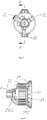
- the electric motor includes a stator assembly 2 and a rotor assembly 7 rotatably disposed in the stator assembly 2.
- the rotor assembly 7 includes a rotating shaft 72.
- the stator assembly 2 includes a stator core 12 and a winding 11 wound around the stator core 12, and the stator assembly 2 further includes an injection-molded enveloping portion 25 coated outside the winding 11 and the stator core 12.
- the injection-molded enveloping portion 25 can be molded with a bulk molding compound (BMC) material, an inner part of the stator core 12 is exposed and other parts of the stator core 12 are all enveloped by the BMC material (the injection-molded enveloping portion 25).
- a front cover 3 and a rear cover 23 for supporting the rotating shaft 72 are embedded in the injection-molded enveloping portion 25 or integrally molded with the injection-molded enveloping portion 25.
- the front cover 3 and the rear cover 23 can be BB covers.
- the front cover 3 and the rear cover 23 can be injection-molded together with the stator assembly 2 while the stator assembly 2 is enveloped by BMC injection-molding, or can be embedded in and secured to the stator assembly 2 by means of being pressed after the injection molding is finished.
- an assembling process of the front cover 3 and the rear cover 23 has high accuracy, so as to significantly reduce noise and vibration of the electric motor, thus effectively enhancing the user experience.
- the stator assembly 2 is enveloped directly by injection molding with the BMC material to form the injection-molded enveloping portion 25, and an end cover is not needed to be mounted to the stator, such that the manufacturing process is simple, and the material cost and the production cost are low.
- stator assembly 2 is entirely enveloped with the injection-molded enveloping portion 25.
- the BMC material envelops the whole semi-finished stator 1, and only a part of an inner cavity 121 of the stator core 12 is exposed, so the stator assembly 2 has a great waterproof effect, which can prevent defects such as an electric leakage or a short circuit from being caused, thus exhibiting great reliability.
- the front cover 3 is pressed and embedded in the injection-molded enveloping portion 25 or is placed in an injection mould to be positioned during the injection molding of the injection-molded enveloping portion 25.
- the rear cover 23 is pressed and embedded in the injection-molded enveloping portion 25 or is placed in the injection mould to be positioned during the injection molding of the injection-molded enveloping portion 25.
- the front cover 3 and the rear cover 23 have high positioning accuracy, and the electric motor has low vibration and noise.
- a power line 13 is connected to the winding 11, and an end of the power line 13 connected with the winding 11 is enveloped by the injection-molded enveloping portion 25, thus providing a great waterproof effect.
- the winding 11 an enameled wire
- the stator core 12 is wound upon the stator core 12, then the power line 13 is welded, and the semi-finished stator 1 is attained after this processing.
- a manufacturing process of the semi-finished stator 1 has advantages of simpleness, high efficiency and a high automatic level with respect to a conventional induction electric motor, thus playing an important role in reducing the production cost.
- the BMC injection molding is carried out to form the injection-molded enveloping portion 25 directly after the manufacturing of semi-finished stator 1 is finished, and the material after the injection molding is namely the stator assembly 2.
- the semi-finished stator 1 does not need to go through a conventional impregnation process, but is enveloped through the BMC injection molding, which is simple and exhibits high efficiency, without a long turnaround period, so the total manufacturing cost is reduced significantly.
- the injection-molded enveloping portion 25 has a first accommodating groove 2501 for accommodating the front cover 3, and the front cover 3 may be pressed and embedded in the first accommodating groove 2501 in an interference manner.
- the front cover 3 has high positioning accuracy, and the electric motor has a stable and quiet operation process.
- a first bearing 61 is provided in the front cover 3, and the rotating shaft 72 has an end running through the first bearing 61.
- the front cover 3 can be placed in the injection mould to be positioned during the injection molding of the injection-molded enveloping portion 25, that is, the front cover 3 can be directly embedded in the injection-molded enveloping portion 25 by insert injection-molding.
- the injection-molded enveloping portion 25 has a second accommodating groove 2502 for accommodating the rear cover 23, an outer side wall of the rear cover 23 abuts a side wall of the second accommodating groove 2502, an end of the rear cover 23 abuts a bottom of the second accommodating groove 2502, the rear cover 23 is integrally molded with a flange 2301 at an outer side thereof, and the flange 2301 is fitted and embedded in the side wall of the second accommodating groove 2502.
- the rear cover 23 has high positioning accuracy, and the electric motor has a stable and quiet operation process.
- a second bearing 62 is provided in the rear cover 23, and the rotating shaft 72 has another end running through the second bearing 62.
- the rear cover 23 can be pressed and embedded in the injection-molded enveloping portion 25.
- the rear cover 23 can be placed in the injection mould to be positioned during the injection molding of the injection-molded enveloping portion 25, that is, the rear cover 23 can be directly embedded in the injection-molded enveloping portion 25 by insert injection-molding.
- the rear cover 23 and the front cover 3 form a supporting structure to support the rotor assembly 7, so that a smooth rotation of the electric motor is realized.
- the rear cover 23 can be placed in the mould to be enveloped by injection molding together with the semi-finished stator 1 while the BMC injection-molding enveloping is carried out for the semi-finished stator 1.
- An end face 231 of the rear cover 23 and an end face 222 of the injection-molded enveloping portion 25 form a pair of blocking surfaces, and an end face 232 of the rear cover 23 and an end face 223 of the injection-molded enveloping portion 25 also form a pair of blocking surfaces, so as to prevent an axial displacement of the rear cover 23.
- An end face 233 of the rear cover 23 and an end face 221 of the injection-molded enveloping portion 25 also form a pair of blocking surfaces, so as to bear an axial force produced by the rear cover 23 and the bearing 62.
- An end face 234 of the rear cover 23 and an end face 224 of the injection-molded enveloping portion 25 form a pair of radial blocking surfaces, so as to prevent a radial displacement of the rear cover 23.
- the front cover 3 is pressed into the injection-molded enveloping portion 25 with a side surface 31 of the front cover 3 being fitted with a side wall 24 of the injection-molded enveloping portion 25 in an interference manner, so that the front cover 3 is immobilized axially and radially.
- the front bearing (the first bearing 61) of the rotor assembly 7 is supported by the front cover 3 and the rear bearing (the second bearing 62) of the rotor assembly 7 is supported by the rear cover 23, so that a front end cover and a rear end cover necessary for the conventional induction electric motor are omitted, which saves the material cost of the electric motor significantly.
- the assembling process and procedure are simpler compared with the conventional induction electric motor, and a quality control level is improved.
- a ventilation blade 71 is connected to the rotor assembly 7, the stator assembly 2 has an inner cavity 20 for accommodating the ventilation blade 71, and the injection-molded enveloping portion 25 is provided with a ventilation hole 26 communicated with the inner cavity 20.
- a plurality of ventilation holes 26 is provided to form an active heat-removal system, which is beneficial for heat dissipation of the BMC material in the winding 11 and the injection-molded enveloping portion 25, and the heat dissipation effect is great, thus improving the reliability of the electric motor and prolonging the service life of the electric motor.
- the ventilation blades 71 can be squirrel-cage blades.
- the front cover 3 and the rear cover 23 have high assembling accuracy, the electric motor has low noise and vibration, and thus the user experience can be improved effectively.
- the stator assembly 2 is enveloped directly by injection molding with the BMC material, so as to form the injection-molded enveloping portion 25, and the end cover is not needed to be mounted to the stator, such that the manufacturing process is simple, and the material cost and the production cost are low.
- the stator assembly 2 is entirely enveloped with the injection-molded enveloping portion 25, to provide a great waterproof effect, so defects such as an electric leakage or a short circuit are prevented from being caused and thus great reliability is exhibited.
- inventions of the present disclosure further provides a washing pump 120.
- the washing pump 120 includes a lower pump housing 41, and further includes the electric motor mentioned above, and the electric motor is connected to the lower pump housing 41.
- the lower pump housing 41 has a protruding post 411
- the stator assembly 2 of the electric motor has a positioning hole 27 for the protruding post 411 to be inserted therein.
- At least two protruding posts 411 and at least two the positioning holes 27 are provided.
- four protruding posts 411 and four positioning holes 27 are provided.
- the stator assembly 2 of the electric motor has the protruding post 411
- the lower pump housing 41 has the positioning hole 27 for the protruding post 411 to be inserted therein.
- the protruding post 411 and the positioning hole 27 are used for assembling and positioning, so as to prevent the lower pump housing 41 from rotating during the assembling, thus providing great reliability.
- a capacitor mounting foot 412 is provided at a side surface of the lower pump housing 41, and the capacitor mounting foot 412 includes a capacitor contacting wall 4123 in contact with a capacitor and connecting ribs 4122, 4124 connected between the capacitor contacting wall 4123 and a side wall of the lower pump housing 41.
- the capacitor mounting foot 412 is integrally injection-molded with the injection-molded enveloping portion 25.
- the capacitor contacting wall 4123 exhibits an arc shape
- two connecting ribs are provided
- the capacitor contacting wall 4123, the two connecting ribs 4122, 4124, and the side surface of the lower pump housing 41 together form a closed annular structure.
- the capacitor mounting foot 412 is provided to the side surface of the lower pump housing 41
- the capacitor contacting wall 4123 of the capacitor mounting foot 412 is connected with the side wall 413 of the lower pump housing 41
- a semi-arc-shaped capacitor contacting wall 4123 is formed at an outer side of the capacitor contacting wall 4123
- the semi-arc-shaped capacitor contacting wall 4123 forms a closed reinforcing rib structure through the connecting rib 4122 and the connecting rib 4124.
- the semi-arc-shaped capacitor contacting wall 4123 is connected to a side wall 415 of the lower pump housing 41 by means of a connecting structure 414 located between the connecting ribs 4122, 4124.
- the capacitor mounting foot 412 has a firm structure, a defect (such as a breakage phenomenon) of the capacitor mounting foot 412 in the using process or the assembling process can be prevented, and thus great reliability is provided.
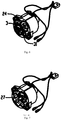
- embodiments of the present disclosure further provide a dishwasher, the dishwasher includes a dishwasher body 900, and the washing pump 120 mentioned above is connected to the dishwasher body 900.
- the stator assembly 2 of the electric motor is enveloped directly by injection molding with the BMC material to form the injection-molded enveloping portion 25, and the end cover is not needed to be mounted to the stator, such that the manufacturing process is simple, and the material cost and the production cost are low.
- the stator assembly 2 is entirely enveloped with the injection-molded enveloping portion 25, to provide a great waterproof effect, so defects such as an electric leakage or a short circuit are prevented from being caused and thus great reliability is exhibited.
- a pump assembly 4 is connected to the washing pump 120, and the pump assembly 4 has a water inlet 423, a first water outlet 421 and a second water outlet 322.
- the water inlet 423 is connected to the dishwasher body 900 through a water-input pipe 140, and the first water outlet 421 and the second water outlet 322 are connected to the dishwasher body 900 through a water-output pipe 130.
- a base plate 150 is arranged in the dishwasher body 900, and an mounting hole site 151 is disposed in the base plate 150.
- the injection-molded enveloping portion 25 of the stator of the electric motor in the washing pump 120 is provided with a rear boss 22 integrally molded with the injection-molded enveloping portion 25, the rear boss 22 is inserted into the mounting hole site 151, and a rear sleeve 160 is connected to the rear boss 22.
- At least two reinforcing ribs 21 are provided at a side surface of the rear boss 22.
- a connection between the dishwasher body 900 and the washing pump 120 includes a connection of the dishwasher body 900 with the water inlet 423 of the pump assembly 4 through the water-input pipe 140 (a rubber pipe), a connection of the dishwasher body 900 with the first water outlet 421 and the second water outlet 322 of the pump assembly 4 through the water-output pipe 130 (a rubber pipe), and a connection of the dishwasher body 900 with the rear boss 22 through the rear sleeve 160, and the three connections are connected with the base plate 150 respectively.
- the rear boss 22 is supported by three reinforcing ribs 21.
- Embodiments of the present disclosure further provide a manufacturing method for an electric motor, which can be used to manufacture the electric motor mentioned above.
- the manufacturing method includes following actions: a stator core 12 and a rotor assembly 7 are produced, a winding 11 is wound upon the stator core 12, a power line 13 is connected to the winding 11 to form a semi-finished stator 1, the semi-finished stator 1 is placed in an injection mould to injection-mold an injection-molded enveloping portion 25 enveloping outer sides of the winding 11 and the stator core 12, a front cover 3 or/and a rear cover 23 for supporting the rotor assembly 7 are pressed and embedded in the injection-molded enveloping portion 25, or the front cover 3 or/and the rear cover 23 for supporting the rotor assembly 7 is placed in the injection mould to be positioned through the injection molding during the injection molding of the injection-molded enveloping portion 25, so a stator assembly 2 is attained, and the rotor assembly 7 is rotatably connected in the stator assembly 2.
- the front cover 3 and the rear cover 23 can be pressed and embedded in the injection-molded enveloping portion 25, or can also be placed in the injection mould to be enveloped and positioned by means of the injection molding during the injection molding of the injection-molded enveloping portion 25.
- the power line 13 is welded to obtain the semi-finished stator 1 after the winding 11 (an enameled wire) is wound upon the stator core 12, and then the semi-finished stator 1 is placed in the injection mould so as to injection-mold the injection-molded enveloping portion 25 coating outer sides of the winding 11 and the stator core 12.
- the front cover 3 and the rear cover 23 can be injection-molded and positioned together with the stator assembly 2 while the stator assembly 2 is enveloped through BMC injection molding, or can also be embedded in and secured to the stator assembly 2 by means of being pressed after the injection molding is finished.
- An assembling process of the front cover 3 and the rear cover 23 has high accuracy, so as to significantly reduce the noise and vibration of the electric motor, thus effectively enhancing the user experience.
- the stator assembly 2 is enveloped directly through injection molding to form the injection-molded enveloping portion 25, and an end cover is not needed to be mounted to the stator, such that the manufacturing process is simple, and the material cost and the production cost are low.
- the stator assembly 2 is entirely enveloped with the injection-molded enveloping portion 25, so the electric motor has a great waterproof effect, and defects such as an electric leakage or a short circuit are prevented from being caused, thus exhibiting great reliability.
Landscapes
- Engineering & Computer Science (AREA)
- Power Engineering (AREA)
- Motor Or Generator Frames (AREA)
Applications Claiming Priority (1)
| Application Number | Priority Date | Filing Date | Title |
|---|---|---|---|
| PCT/CN2015/082636 WO2017000113A1 (zh) | 2015-06-29 | 2015-06-29 | 电机、洗涤泵、洗碗机和电机的制造方法 |
Publications (2)
| Publication Number | Publication Date |
|---|---|
| EP3316455A1 true EP3316455A1 (de) | 2018-05-02 |
| EP3316455A4 EP3316455A4 (de) | 2018-06-13 |
Family
ID=57607382
Family Applications (1)
| Application Number | Title | Priority Date | Filing Date |
|---|---|---|---|
| EP15896644.0A Withdrawn EP3316455A4 (de) | 2015-06-29 | 2015-06-29 | Motor, waschpumpe, geschirrspüler und herstellungsverfahren |
Country Status (3)
| Country | Link |
|---|---|
| EP (1) | EP3316455A4 (de) |
| BR (1) | BR112017028453A2 (de) |
| WO (1) | WO2017000113A1 (de) |
Families Citing this family (1)
| Publication number | Priority date | Publication date | Assignee | Title |
|---|---|---|---|---|
| CN111009994B (zh) * | 2018-10-08 | 2026-04-21 | 佛山市威灵洗涤电机制造有限公司 | 用于洗碗机的水泵和具有其的洗碗机 |
Family Cites Families (9)
| Publication number | Priority date | Publication date | Assignee | Title |
|---|---|---|---|---|
| ITBO20120229A1 (it) * | 2012-04-26 | 2013-10-27 | Spal Automotive Srl | Macchina elettrica. |
| CN104412490B (zh) * | 2012-06-18 | 2017-02-22 | 松下知识产权经营株式会社 | 电动机 |
| EP2908408B1 (de) * | 2012-10-15 | 2019-05-01 | Mitsubishi Electric Corporation | Geformter motor und klimaanlage |
| CN203014542U (zh) * | 2012-11-15 | 2013-06-19 | 湖州永昌贝诗讬电器实业有限公司 | 一种洗衣机用塑封电机 |
| CN203039461U (zh) * | 2012-11-23 | 2013-07-03 | 珠海格力电器股份有限公司 | 一种新型塑封电机定子端盖 |
| CN203871953U (zh) * | 2014-05-21 | 2014-10-08 | 嵊州市精达电机有限公司 | 一种塑封电机 |
| CN104022592B (zh) * | 2014-05-29 | 2018-11-09 | 广东威灵电机制造有限公司 | 电机及电机的制造方法 |
| CN204089433U (zh) * | 2014-08-01 | 2015-01-07 | 广东威灵电机制造有限公司 | 塑封电机 |
| CN104333175B (zh) * | 2014-10-22 | 2017-12-29 | 广东威灵电机制造有限公司 | 电机和具有它的洗涤泵 |
-
2015
- 2015-06-29 EP EP15896644.0A patent/EP3316455A4/de not_active Withdrawn
- 2015-06-29 WO PCT/CN2015/082636 patent/WO2017000113A1/zh not_active Ceased
- 2015-06-29 BR BR112017028453A patent/BR112017028453A2/pt not_active Application Discontinuation
Also Published As
| Publication number | Publication date |
|---|---|
| WO2017000113A1 (zh) | 2017-01-05 |
| BR112017028453A2 (pt) | 2018-08-28 |
| EP3316455A4 (de) | 2018-06-13 |
Similar Documents
| Publication | Publication Date | Title |
|---|---|---|
| CN206770245U (zh) | 风扇马达 | |
| CN106208455B (zh) | 转子、电机、泵及清洗装置 | |
| JP2018093710A (ja) | アウターロータモータ及びこれを備える掃除機 | |
| US7578149B2 (en) | Motor as a direct drive and method for installation of the motor | |
| CN108223393A (zh) | 用于洗碗机的洗涤泵和具有其的洗碗机 | |
| JP2016144394A (ja) | 電気モータ | |
| AU2020342033B2 (en) | Stator | |
| KR20160071350A (ko) | 펌프 및 세척 장치 | |
| CN105048658A (zh) | 电机、洗涤泵、洗碗机和电机的制造方法 | |
| KR102166718B1 (ko) | 제어부 일체형 모터 및 이를 포함한 워터 펌프 | |
| US10250090B2 (en) | Rotor, motor, pump and cleaning apparatus | |
| WO2016155271A1 (zh) | 一种直流无刷电机 | |
| KR102087523B1 (ko) | 팬 모터 | |
| JP6722440B2 (ja) | 同期モータ、モータステータ、ポンプ及び洗浄装置 | |
| KR100917197B1 (ko) | 팬 모터 | |
| CN110460171A (zh) | 一种泵阀用电机定子及其装配方法 | |
| CN212850164U (zh) | 一种注塑定子及外转子电机 | |
| CN224053964U (zh) | 洗衣机及其智嵌一体式高效注塑驱动电机 | |
| WO2017000113A1 (zh) | 电机、洗涤泵、洗碗机和电机的制造方法 | |
| KR20140114582A (ko) | 모터의 로터 및 이를 제작하는 방법 | |
| KR100904428B1 (ko) | 팬 모터 | |
| CN206834951U (zh) | 无刷外转子电机 | |
| CN220544766U (zh) | 电机和电器 | |
| KR102061627B1 (ko) | 모터 어셈블리 | |
| JP6711603B2 (ja) | モータ、ステータコア、ポンプ、及び洗浄装置 |
Legal Events
| Date | Code | Title | Description |
|---|---|---|---|
| STAA | Information on the status of an ep patent application or granted ep patent |
Free format text: STATUS: THE INTERNATIONAL PUBLICATION HAS BEEN MADE |
|
| PUAI | Public reference made under article 153(3) epc to a published international application that has entered the european phase |
Free format text: ORIGINAL CODE: 0009012 |
|
| STAA | Information on the status of an ep patent application or granted ep patent |
Free format text: STATUS: REQUEST FOR EXAMINATION WAS MADE |
|
| 17P | Request for examination filed |
Effective date: 20180110 |
|
| AK | Designated contracting states |
Kind code of ref document: A1 Designated state(s): AL AT BE BG CH CY CZ DE DK EE ES FI FR GB GR HR HU IE IS IT LI LT LU LV MC MK MT NL NO PL PT RO RS SE SI SK SM TR |
|
| AX | Request for extension of the european patent |
Extension state: BA ME |
|
| A4 | Supplementary search report drawn up and despatched |
Effective date: 20180516 |
|
| RIC1 | Information provided on ipc code assigned before grant |
Ipc: H02K 5/15 20060101ALN20180509BHEP Ipc: H02K 5/12 20060101ALI20180509BHEP Ipc: H02K 5/10 20060101ALN20180509BHEP Ipc: H02K 17/08 20060101ALI20180509BHEP Ipc: H02K 5/16 20060101ALI20180509BHEP Ipc: H02K 9/06 20060101ALN20180509BHEP Ipc: H02K 7/14 20060101ALN20180509BHEP Ipc: H02K 5/08 20060101ALN20180509BHEP Ipc: H02K 5/04 20060101AFI20180509BHEP |
|
| DAV | Request for validation of the european patent (deleted) | ||
| DAX | Request for extension of the european patent (deleted) | ||
| STAA | Information on the status of an ep patent application or granted ep patent |
Free format text: STATUS: THE APPLICATION IS DEEMED TO BE WITHDRAWN |
|
| 18D | Application deemed to be withdrawn |
Effective date: 20181215 |