EP3316469A1 - Stromumwandlungsvorrichtung und konfigurationsverfahren dafür - Google Patents
Stromumwandlungsvorrichtung und konfigurationsverfahren dafür Download PDFInfo
- Publication number
- EP3316469A1 EP3316469A1 EP15896158.1A EP15896158A EP3316469A1 EP 3316469 A1 EP3316469 A1 EP 3316469A1 EP 15896158 A EP15896158 A EP 15896158A EP 3316469 A1 EP3316469 A1 EP 3316469A1
- Authority
- EP
- European Patent Office
- Prior art keywords
- conversion
- power conversion
- subunit
- isolated
- unit
- Prior art date
- Legal status (The legal status is an assumption and is not a legal conclusion. Google has not performed a legal analysis and makes no representation as to the accuracy of the status listed.)
- Ceased
Links
Images





Classifications
-
- H—ELECTRICITY
- H02—GENERATION; CONVERSION OR DISTRIBUTION OF ELECTRIC POWER
- H02M—APPARATUS FOR CONVERSION BETWEEN AC AND AC, BETWEEN AC AND DC, OR BETWEEN DC AND DC, AND FOR USE WITH MAINS OR SIMILAR POWER SUPPLY SYSTEMS; CONVERSION OF DC OR AC INPUT POWER INTO SURGE OUTPUT POWER; CONTROL OR REGULATION THEREOF
- H02M3/00—Conversion of DC power input into DC power output
- H02M3/02—Conversion of DC power input into DC power output without intermediate conversion into AC
- H02M3/04—Conversion of DC power input into DC power output without intermediate conversion into AC by static converters
- H02M3/10—Conversion of DC power input into DC power output without intermediate conversion into AC by static converters using discharge tubes with control electrode or semiconductor devices with control electrode
- H02M3/145—Conversion of DC power input into DC power output without intermediate conversion into AC by static converters using discharge tubes with control electrode or semiconductor devices with control electrode using devices of a triode or transistor type requiring continuous application of a control signal
- H02M3/155—Conversion of DC power input into DC power output without intermediate conversion into AC by static converters using discharge tubes with control electrode or semiconductor devices with control electrode using devices of a triode or transistor type requiring continuous application of a control signal using semiconductor devices only
- H02M3/156—Conversion of DC power input into DC power output without intermediate conversion into AC by static converters using discharge tubes with control electrode or semiconductor devices with control electrode using devices of a triode or transistor type requiring continuous application of a control signal using semiconductor devices only with automatic control of output voltage or current, e.g. switching regulators
- H02M3/158—Conversion of DC power input into DC power output without intermediate conversion into AC by static converters using discharge tubes with control electrode or semiconductor devices with control electrode using devices of a triode or transistor type requiring continuous application of a control signal using semiconductor devices only with automatic control of output voltage or current, e.g. switching regulators including plural semiconductor devices as final control devices for a single load
- H02M3/1584—Conversion of DC power input into DC power output without intermediate conversion into AC by static converters using discharge tubes with control electrode or semiconductor devices with control electrode using devices of a triode or transistor type requiring continuous application of a control signal using semiconductor devices only with automatic control of output voltage or current, e.g. switching regulators including plural semiconductor devices as final control devices for a single load with a plurality of power processing stages connected in parallel
-
- H—ELECTRICITY
- H02—GENERATION; CONVERSION OR DISTRIBUTION OF ELECTRIC POWER
- H02M—APPARATUS FOR CONVERSION BETWEEN AC AND AC, BETWEEN AC AND DC, OR BETWEEN DC AND DC, AND FOR USE WITH MAINS OR SIMILAR POWER SUPPLY SYSTEMS; CONVERSION OF DC OR AC INPUT POWER INTO SURGE OUTPUT POWER; CONTROL OR REGULATION THEREOF
- H02M7/00—Conversion of AC power input into DC power output; Conversion of DC power input into AC power output
- H02M7/02—Conversion of AC power input into DC power output without possibility of reversal
- H02M7/04—Conversion of AC power input into DC power output without possibility of reversal by static converters
- H02M7/12—Conversion of AC power input into DC power output without possibility of reversal by static converters using discharge tubes with control electrode or semiconductor devices with control electrode
- H02M7/21—Conversion of AC power input into DC power output without possibility of reversal by static converters using discharge tubes with control electrode or semiconductor devices with control electrode using devices of a triode or transistor type requiring continuous application of a control signal
- H02M7/217—Conversion of AC power input into DC power output without possibility of reversal by static converters using discharge tubes with control electrode or semiconductor devices with control electrode using devices of a triode or transistor type requiring continuous application of a control signal using semiconductor devices only
- H02M7/219—Conversion of AC power input into DC power output without possibility of reversal by static converters using discharge tubes with control electrode or semiconductor devices with control electrode using devices of a triode or transistor type requiring continuous application of a control signal using semiconductor devices only in a bridge configuration
-
- H—ELECTRICITY
- H02—GENERATION; CONVERSION OR DISTRIBUTION OF ELECTRIC POWER
- H02M—APPARATUS FOR CONVERSION BETWEEN AC AND AC, BETWEEN AC AND DC, OR BETWEEN DC AND DC, AND FOR USE WITH MAINS OR SIMILAR POWER SUPPLY SYSTEMS; CONVERSION OF DC OR AC INPUT POWER INTO SURGE OUTPUT POWER; CONTROL OR REGULATION THEREOF
- H02M1/00—Details of apparatus for conversion
- H02M1/42—Circuits or arrangements for compensating for or adjusting power factor in converters or inverters
- H02M1/4208—Arrangements for improving power factor of AC input
- H02M1/4225—Arrangements for improving power factor of AC input using a non-isolated boost converter
-
- H—ELECTRICITY
- H02—GENERATION; CONVERSION OR DISTRIBUTION OF ELECTRIC POWER
- H02M—APPARATUS FOR CONVERSION BETWEEN AC AND AC, BETWEEN AC AND DC, OR BETWEEN DC AND DC, AND FOR USE WITH MAINS OR SIMILAR POWER SUPPLY SYSTEMS; CONVERSION OF DC OR AC INPUT POWER INTO SURGE OUTPUT POWER; CONTROL OR REGULATION THEREOF
- H02M3/00—Conversion of DC power input into DC power output
- H02M3/01—Resonant DC/DC converters
-
- H—ELECTRICITY
- H02—GENERATION; CONVERSION OR DISTRIBUTION OF ELECTRIC POWER
- H02M—APPARATUS FOR CONVERSION BETWEEN AC AND AC, BETWEEN AC AND DC, OR BETWEEN DC AND DC, AND FOR USE WITH MAINS OR SIMILAR POWER SUPPLY SYSTEMS; CONVERSION OF DC OR AC INPUT POWER INTO SURGE OUTPUT POWER; CONTROL OR REGULATION THEREOF
- H02M3/00—Conversion of DC power input into DC power output
- H02M3/02—Conversion of DC power input into DC power output without intermediate conversion into AC
- H02M3/04—Conversion of DC power input into DC power output without intermediate conversion into AC by static converters
- H02M3/10—Conversion of DC power input into DC power output without intermediate conversion into AC by static converters using discharge tubes with control electrode or semiconductor devices with control electrode
- H02M3/145—Conversion of DC power input into DC power output without intermediate conversion into AC by static converters using discharge tubes with control electrode or semiconductor devices with control electrode using devices of a triode or transistor type requiring continuous application of a control signal
- H02M3/155—Conversion of DC power input into DC power output without intermediate conversion into AC by static converters using discharge tubes with control electrode or semiconductor devices with control electrode using devices of a triode or transistor type requiring continuous application of a control signal using semiconductor devices only
-
- H—ELECTRICITY
- H02—GENERATION; CONVERSION OR DISTRIBUTION OF ELECTRIC POWER
- H02M—APPARATUS FOR CONVERSION BETWEEN AC AND AC, BETWEEN AC AND DC, OR BETWEEN DC AND DC, AND FOR USE WITH MAINS OR SIMILAR POWER SUPPLY SYSTEMS; CONVERSION OF DC OR AC INPUT POWER INTO SURGE OUTPUT POWER; CONTROL OR REGULATION THEREOF
- H02M3/00—Conversion of DC power input into DC power output
- H02M3/22—Conversion of DC power input into DC power output with intermediate conversion into AC
- H02M3/24—Conversion of DC power input into DC power output with intermediate conversion into AC by static converters
- H02M3/28—Conversion of DC power input into DC power output with intermediate conversion into AC by static converters using discharge tubes with control electrode or semiconductor devices with control electrode to produce the intermediate AC
- H02M3/325—Conversion of DC power input into DC power output with intermediate conversion into AC by static converters using discharge tubes with control electrode or semiconductor devices with control electrode to produce the intermediate AC using devices of a triode or a transistor type requiring continuous application of a control signal
- H02M3/335—Conversion of DC power input into DC power output with intermediate conversion into AC by static converters using discharge tubes with control electrode or semiconductor devices with control electrode to produce the intermediate AC using devices of a triode or a transistor type requiring continuous application of a control signal using semiconductor devices only
- H02M3/3353—Conversion of DC power input into DC power output with intermediate conversion into AC by static converters using discharge tubes with control electrode or semiconductor devices with control electrode to produce the intermediate AC using devices of a triode or a transistor type requiring continuous application of a control signal using semiconductor devices only having at least two simultaneously operating switches on the input side, e.g. "double forward" or "double (switched) flyback" converter
-
- H—ELECTRICITY
- H02—GENERATION; CONVERSION OR DISTRIBUTION OF ELECTRIC POWER
- H02M—APPARATUS FOR CONVERSION BETWEEN AC AND AC, BETWEEN AC AND DC, OR BETWEEN DC AND DC, AND FOR USE WITH MAINS OR SIMILAR POWER SUPPLY SYSTEMS; CONVERSION OF DC OR AC INPUT POWER INTO SURGE OUTPUT POWER; CONTROL OR REGULATION THEREOF
- H02M3/00—Conversion of DC power input into DC power output
- H02M3/22—Conversion of DC power input into DC power output with intermediate conversion into AC
- H02M3/24—Conversion of DC power input into DC power output with intermediate conversion into AC by static converters
- H02M3/28—Conversion of DC power input into DC power output with intermediate conversion into AC by static converters using discharge tubes with control electrode or semiconductor devices with control electrode to produce the intermediate AC
- H02M3/325—Conversion of DC power input into DC power output with intermediate conversion into AC by static converters using discharge tubes with control electrode or semiconductor devices with control electrode to produce the intermediate AC using devices of a triode or a transistor type requiring continuous application of a control signal
- H02M3/335—Conversion of DC power input into DC power output with intermediate conversion into AC by static converters using discharge tubes with control electrode or semiconductor devices with control electrode to produce the intermediate AC using devices of a triode or a transistor type requiring continuous application of a control signal using semiconductor devices only
- H02M3/33569—Conversion of DC power input into DC power output with intermediate conversion into AC by static converters using discharge tubes with control electrode or semiconductor devices with control electrode to produce the intermediate AC using devices of a triode or a transistor type requiring continuous application of a control signal using semiconductor devices only having several active switching elements
- H02M3/33571—Half-bridge at primary side of an isolation transformer
-
- H—ELECTRICITY
- H02—GENERATION; CONVERSION OR DISTRIBUTION OF ELECTRIC POWER
- H02M—APPARATUS FOR CONVERSION BETWEEN AC AND AC, BETWEEN AC AND DC, OR BETWEEN DC AND DC, AND FOR USE WITH MAINS OR SIMILAR POWER SUPPLY SYSTEMS; CONVERSION OF DC OR AC INPUT POWER INTO SURGE OUTPUT POWER; CONTROL OR REGULATION THEREOF
- H02M3/00—Conversion of DC power input into DC power output
- H02M3/22—Conversion of DC power input into DC power output with intermediate conversion into AC
- H02M3/24—Conversion of DC power input into DC power output with intermediate conversion into AC by static converters
- H02M3/28—Conversion of DC power input into DC power output with intermediate conversion into AC by static converters using discharge tubes with control electrode or semiconductor devices with control electrode to produce the intermediate AC
- H02M3/325—Conversion of DC power input into DC power output with intermediate conversion into AC by static converters using discharge tubes with control electrode or semiconductor devices with control electrode to produce the intermediate AC using devices of a triode or a transistor type requiring continuous application of a control signal
- H02M3/335—Conversion of DC power input into DC power output with intermediate conversion into AC by static converters using discharge tubes with control electrode or semiconductor devices with control electrode to produce the intermediate AC using devices of a triode or a transistor type requiring continuous application of a control signal using semiconductor devices only
- H02M3/33569—Conversion of DC power input into DC power output with intermediate conversion into AC by static converters using discharge tubes with control electrode or semiconductor devices with control electrode to produce the intermediate AC using devices of a triode or a transistor type requiring continuous application of a control signal using semiconductor devices only having several active switching elements
- H02M3/33573—Full-bridge at primary side of an isolation transformer
-
- H—ELECTRICITY
- H02—GENERATION; CONVERSION OR DISTRIBUTION OF ELECTRIC POWER
- H02M—APPARATUS FOR CONVERSION BETWEEN AC AND AC, BETWEEN AC AND DC, OR BETWEEN DC AND DC, AND FOR USE WITH MAINS OR SIMILAR POWER SUPPLY SYSTEMS; CONVERSION OF DC OR AC INPUT POWER INTO SURGE OUTPUT POWER; CONTROL OR REGULATION THEREOF
- H02M3/00—Conversion of DC power input into DC power output
- H02M3/22—Conversion of DC power input into DC power output with intermediate conversion into AC
- H02M3/24—Conversion of DC power input into DC power output with intermediate conversion into AC by static converters
- H02M3/28—Conversion of DC power input into DC power output with intermediate conversion into AC by static converters using discharge tubes with control electrode or semiconductor devices with control electrode to produce the intermediate AC
- H02M3/325—Conversion of DC power input into DC power output with intermediate conversion into AC by static converters using discharge tubes with control electrode or semiconductor devices with control electrode to produce the intermediate AC using devices of a triode or a transistor type requiring continuous application of a control signal
- H02M3/335—Conversion of DC power input into DC power output with intermediate conversion into AC by static converters using discharge tubes with control electrode or semiconductor devices with control electrode to produce the intermediate AC using devices of a triode or a transistor type requiring continuous application of a control signal using semiconductor devices only
- H02M3/33569—Conversion of DC power input into DC power output with intermediate conversion into AC by static converters using discharge tubes with control electrode or semiconductor devices with control electrode to produce the intermediate AC using devices of a triode or a transistor type requiring continuous application of a control signal using semiconductor devices only having several active switching elements
- H02M3/33576—Conversion of DC power input into DC power output with intermediate conversion into AC by static converters using discharge tubes with control electrode or semiconductor devices with control electrode to produce the intermediate AC using devices of a triode or a transistor type requiring continuous application of a control signal using semiconductor devices only having several active switching elements having at least one active switching element at the secondary side of an isolation transformer
- H02M3/33592—Conversion of DC power input into DC power output with intermediate conversion into AC by static converters using discharge tubes with control electrode or semiconductor devices with control electrode to produce the intermediate AC using devices of a triode or a transistor type requiring continuous application of a control signal using semiconductor devices only having several active switching elements having at least one active switching element at the secondary side of an isolation transformer having a synchronous rectifier circuit or a synchronous freewheeling circuit at the secondary side of an isolation transformer
-
- H—ELECTRICITY
- H02—GENERATION; CONVERSION OR DISTRIBUTION OF ELECTRIC POWER
- H02M—APPARATUS FOR CONVERSION BETWEEN AC AND AC, BETWEEN AC AND DC, OR BETWEEN DC AND DC, AND FOR USE WITH MAINS OR SIMILAR POWER SUPPLY SYSTEMS; CONVERSION OF DC OR AC INPUT POWER INTO SURGE OUTPUT POWER; CONTROL OR REGULATION THEREOF
- H02M7/00—Conversion of AC power input into DC power output; Conversion of DC power input into AC power output
- H02M7/02—Conversion of AC power input into DC power output without possibility of reversal
- H02M7/04—Conversion of AC power input into DC power output without possibility of reversal by static converters
- H02M7/12—Conversion of AC power input into DC power output without possibility of reversal by static converters using discharge tubes with control electrode or semiconductor devices with control electrode
- H02M7/21—Conversion of AC power input into DC power output without possibility of reversal by static converters using discharge tubes with control electrode or semiconductor devices with control electrode using devices of a triode or transistor type requiring continuous application of a control signal
-
- H—ELECTRICITY
- H02—GENERATION; CONVERSION OR DISTRIBUTION OF ELECTRIC POWER
- H02M—APPARATUS FOR CONVERSION BETWEEN AC AND AC, BETWEEN AC AND DC, OR BETWEEN DC AND DC, AND FOR USE WITH MAINS OR SIMILAR POWER SUPPLY SYSTEMS; CONVERSION OF DC OR AC INPUT POWER INTO SURGE OUTPUT POWER; CONTROL OR REGULATION THEREOF
- H02M1/00—Details of apparatus for conversion
- H02M1/0067—Converter structures employing plural converter units, other than for parallel operation of the units on a single load
- H02M1/007—Plural converter units in cascade
-
- H—ELECTRICITY
- H02—GENERATION; CONVERSION OR DISTRIBUTION OF ELECTRIC POWER
- H02M—APPARATUS FOR CONVERSION BETWEEN AC AND AC, BETWEEN AC AND DC, OR BETWEEN DC AND DC, AND FOR USE WITH MAINS OR SIMILAR POWER SUPPLY SYSTEMS; CONVERSION OF DC OR AC INPUT POWER INTO SURGE OUTPUT POWER; CONTROL OR REGULATION THEREOF
- H02M1/00—Details of apparatus for conversion
- H02M1/0067—Converter structures employing plural converter units, other than for parallel operation of the units on a single load
- H02M1/0074—Plural converter units whose inputs are connected in series
-
- H—ELECTRICITY
- H02—GENERATION; CONVERSION OR DISTRIBUTION OF ELECTRIC POWER
- H02M—APPARATUS FOR CONVERSION BETWEEN AC AND AC, BETWEEN AC AND DC, OR BETWEEN DC AND DC, AND FOR USE WITH MAINS OR SIMILAR POWER SUPPLY SYSTEMS; CONVERSION OF DC OR AC INPUT POWER INTO SURGE OUTPUT POWER; CONTROL OR REGULATION THEREOF
- H02M1/00—Details of apparatus for conversion
- H02M1/0083—Converters characterised by their input or output configuration
- H02M1/0085—Partially controlled bridges
-
- Y—GENERAL TAGGING OF NEW TECHNOLOGICAL DEVELOPMENTS; GENERAL TAGGING OF CROSS-SECTIONAL TECHNOLOGIES SPANNING OVER SEVERAL SECTIONS OF THE IPC; TECHNICAL SUBJECTS COVERED BY FORMER USPC CROSS-REFERENCE ART COLLECTIONS [XRACs] AND DIGESTS
- Y02—TECHNOLOGIES OR APPLICATIONS FOR MITIGATION OR ADAPTATION AGAINST CLIMATE CHANGE
- Y02B—CLIMATE CHANGE MITIGATION TECHNOLOGIES RELATED TO BUILDINGS, e.g. HOUSING, HOUSE APPLIANCES OR RELATED END-USER APPLICATIONS
- Y02B70/00—Technologies for an efficient end-user side electric power management and consumption
- Y02B70/10—Technologies improving the efficiency by using switched-mode power supplies [SMPS], i.e. efficient power electronics conversion e.g. power factor correction or reduction of losses in power supplies or efficient standby modes
-
- Y—GENERAL TAGGING OF NEW TECHNOLOGICAL DEVELOPMENTS; GENERAL TAGGING OF CROSS-SECTIONAL TECHNOLOGIES SPANNING OVER SEVERAL SECTIONS OF THE IPC; TECHNICAL SUBJECTS COVERED BY FORMER USPC CROSS-REFERENCE ART COLLECTIONS [XRACs] AND DIGESTS
- Y02—TECHNOLOGIES OR APPLICATIONS FOR MITIGATION OR ADAPTATION AGAINST CLIMATE CHANGE
- Y02P—CLIMATE CHANGE MITIGATION TECHNOLOGIES IN THE PRODUCTION OR PROCESSING OF GOODS
- Y02P80/00—Climate change mitigation technologies for sector-wide applications
- Y02P80/10—Efficient use of energy, e.g. using compressed air or pressurized fluid as energy carrier
Definitions
- the present invention relates to the field of power conversion, and specifically, to a power conversion apparatus and a method for configuring the same.
- a single power converter adopts a two-stage structure.
- a power factor correction (PFC) unit implements a pre-regulated voltage for alternating current-direct current (AC-DC).
- a DC-DC conversion unit converts the pre-regulated voltage into a required output voltage.
- a stress of a switching device is relatively high, and a volume of a magnetic device is large as well, resulting in no advantage in terms of efficiency and volume in medium and high-power applications.
- a common practice is to realize multiphase parallel connection on the PFC unit or DC-DC unit, which may reduce the stress of the device and the volume of the magnetic part.
- the efficiency and heat dissipation are improved, and meanwhile, input and output current ripples are reduced by utilizing interleaved control.
- the related technologies such as employing interleaved PFC, employing coupled inductance, a DC-DC isolation transformer employing a matrix transformer, etc., are to some extent contribute to improving the efficiency and the power density, but they may not effectively reduce the volume of the magnetic part and the stress of the switching device, and may not achieve automatic current sharing, in which an additional current-sharing control is required to be added and a control complexity of a system is also increased.
- a problem to be solved by the present invention is to provide a power conversion apparatus and a method for configuring the same, so as to solve problems of large volume and stress and complicated control of the existing power converter.
- the present invention provides a power conversion apparatus.
- the power conversion apparatus includes a boost unit and at least two power conversion units, wherein each of the power conversion units has two input ends and two output ends; an input end of the boost unit is connected with one end of an alternating-current power supply, and an output end of the boost unit is connected with one input end of a first power conversion unit of the plurality of power conversion units; one input end of a last power conversion unit of the plurality of power conversion units is connected with the other end of the alternating-current power supply; and the input ends of the plurality of power conversion units are connected in series, and the output ends of the plurality of power conversion units are connected in parallel.
- each of the power conversion units includes a first conversion subunit and a second conversion subunit respectively with two input ends and two output ends; the two output ends of the first conversion subunit of each power conversion unit are respectively connected with the two input ends of the second conversion subunit; the two output ends of the second conversion subunits of the power conversion units are respectively connected in parallel; and the input ends of the first conversion subunits of the power conversion units are sequentially connected in series; one input end of the first conversion subunit of the first power conversion unit is connected with the output end of the boost unit; and one input end of the first conversion subunit of the last power conversion unit is connected with the other end of the alternating-current power supply.
- the first conversion subunit is a non-isolated alternating current-direct current (AC-DC) conversion subunit or a non-isolated DC-DC conversion subunit
- the second conversion subunit is an isolated DC-DC conversion subunit
- the non-isolated AC-DC conversion subunit when the first conversion subunit is the non-isolated AC-DC conversion subunit, the non-isolated AC-DC conversion subunit is an H-bridge circuit conversion subunit or a bidirectional switch H-bridge circuit conversion subunit; when the first conversion subunit is the non-isolated DC-DC conversion subunit, the non-isolated DC-DC conversion subunit is a half-bridge circuit conversion subunit; and the isolated DC-DC conversion subunit is an LLC half-bridge circuit conversion subunit or an LLC full-bridge circuit conversion subunit.
- the power conversion apparatus when the first conversion subunit is the non-isolated DC-DC conversion subunit, the power conversion apparatus further includes a rectification unit configured to convert an alternating current into a direct current, wherein the one input end of the first conversion subunit of the first power conversion unit is connected with the one end of the alternating-current power supply through the boost unit and the rectification unit; and the one input end of the first conversion subunit of the last power conversion unit is connected with the other end of the alternating-current power supply through the rectification unit.
- a rectification unit configured to convert an alternating current into a direct current
- each of the power conversion units includes a third conversion subunit, and two output ends of the third conversion subunits of the power conversion units are respectively connected in parallel; and input ends of the third conversion subunits of the power conversion units are sequentially connected in series; one input end of the third conversion subunit of the first power conversion unit is connected with the output end of the boost unit; and one input end of the third conversion subunit of the last power conversion unit is connected with the other end of the alternating-current power supply.
- the third conversion subunit is an isolated AC-DC conversion subunit.
- the boost unit includes at least one inductor.
- the present invention further provides a method for configuring a power conversion apparatus.
- the power conversion apparatus includes a boost unit and at least two power conversion units, each of the power conversion units having two input ends and two output ends.
- the method includes: connecting an input end of the boost unit with one end of an alternating-current power supply, and connecting an output end of the boost unit with one input end of a first power conversion unit of the plurality of power conversion units; connecting one input end of a last power conversion unit of the plurality of power conversion units with the other end of the alternating-current power supply; and connecting the input ends of the plurality of power conversion units in series and the output ends of the plurality of power conversion units in parallel.
- the present invention has beneficial effects as follows.
- the present invention provides a power conversion apparatus and a method for configuring the same.
- the power conversion apparatus includes a boost unit and at least two power conversion units; each of the power conversion units has two input ends; an input end of the boost unit is connected with one end of an alternating-current power supply, and an output end of the boost unit is connected with one input end of a first power conversion unit of the plurality of power conversion units; one input end of a last power conversion unit of the plurality of power conversion units is connected with the other end of the alternating-current power supply; and the input ends of the plurality of power conversion units are connected in series, and the output ends of the plurality of power conversion units are connected in parallel.
- the voltage stress and the current stress on the switching device may be 1/n times those of the existing power conversion apparatus, so that switching and conduction losses may be reduced.
- an input inductance of a PFC unit is significantly reduced, thereby reducing the volume of the inductor and increasing the power density.
- the structure also makes the power conversion apparatus of the present invention have an automatic current sharing function and control on the power conversion apparatus be relatively simple and reliable.
- a voltage stress and a current stress of a switching device may be reduced by connecting input ends of a plurality of power conversion units of a power conversion apparatus in series and connecting output ends thereof in parallel, so as to reduce switching and conduction losses of the switching device; and under the same ripple condition, an input inductance of a PFC unit is significantly reduced, a volume of the inductor is decreased, and the power density is increased; and meanwhile, such a structure also has an automatic current sharing function, and control on the structure is relatively simple.
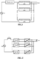
- the power conversion apparatus shown in the embodiment includes a boost unit and at least two power conversion units.
- Each of the power conversion unit has two input ends.
- An input end of the boost unit is connected with one end of an alternating-current power supply and an output end of the boost unit is connected with one input end of a first power conversion unit of the plurality of power conversion units.
- One input end of the last power conversion unit of the plurality of power conversion units is connected with the other end of the alternating-current power supply.
- the input ends of the plurality of power conversion units are connected in series, and output ends thereof are connected in parallel.
- the embodiment can make a voltage stress and a current stress on a switching device be 1/n times those of the existing power conversion apparatus, so that switching and conduction losses can be reduced. Moreover, under the same ripple condition, an input inductance of a PFC unit is decreased significantly, and then the volume of the inductor can be reduced, and the power density is increased. Meanwhile, the power conversion apparatus can also have an automatic current sharing function and control thereon is relatively simple and reliable.
- each of the power conversion units in the embodiment has two input ends and two output ends.
- each of the power conversion units includes a first conversion subunit with two input ends and two output ends and a second conversion subunit with two input ends and two output ends respectively.
- the two output ends of the first conversion subunit of each power conversion unit are respectively connected with the two input ends of the second conversion subunit.
- the two output ends of the second conversion subunits of the power conversion unit are respectively connected in parallel.
- the input ends of the first conversion subunits of the power conversion units are sequentially connected in series.
- One input end of the first conversion subunit of the first power conversion unit and one input end of the first conversion subunit of the last power conversion unit are connected with two ends of the alternating-current power supply, respectively.
- the input end of the first conversion subunit of the first power conversion unit may be connected with the alternating-current power supply through the boost unit.
- the boost unit may specifically employ various boost devices or circuits. It will be exemplarily illustrated by using an inductor L as an example.
- the first conversion subunit may be a non-isolated AC-DC conversion subunit or a non-isolated DC-DC conversion subunit
- the second conversion subunit may be an isolated DC-DC conversion subunit.
- the non-isolated AC-DC conversion subunit may be an H-bridge circuit conversion subunit or a bidirectional switch H-bridge circuit conversion subunit.
- the non-isolated DC-DC conversion subunit may be a half-bridge circuit conversion subunit.
- the isolated DC-DC conversion subunit may be an LLC half-bridge circuit conversion subunit or an LLC full-bridge circuit conversion subunit.
- the LLC may be a series-parallel resonant converter.
- the power conversion apparatus may further include a rectification unit.
- the input end of the first conversion subunit of the first power conversion unit is connected with the one end of the alternating-current power supply through the boost unit and the rectification unit.
- the input end of the first conversion subunit of the last power conversion unit is connected with the other end of the alternating-current power supply through the rectification unit.
- the power conversion apparatus shown in the FIG. 2 includes N power conversion units.
- Each of the power conversion units may include a first conversion subunit that is a non-isolated AC-DC conversion subunit (i.e., an upfront voltage pre-regulation unit), and a second conversion subunit that is an isolated DC-DC conversion subunit.
- the boost unit may be a boost inductor. The specific connection manner thereof is as follows.
- One end of an input alternating-current power supply (Vin) is connected with one end of the boost inductor L.
- One input end of a non-isolated AC-DC conversion subunit of a first power conversion unit is connected with the other end of the boost inductor L.
- the other input end of the first non-isolated AC-DC conversion subunit is connected with one input end of a second non-isolated AC-DC conversion subunit, that is, the input ends of the first non-isolated AC-DC conversion subunit and the second non-isolated AC-DC conversion subunit are connected in series.
- the other input end of the second non-isolated AC-DC conversion subunit is connected with one input end of a third non-isolated AC-DC conversion subunit, that is, the input ends of the second non-isolated AC-DC conversion subunit and the third non-isolated AC-DC conversion subunit are also connected in series, and so on, input ends of a (N-1) h non-isolated AC-DC conversion subunit and a N th non-isolated AC-DC conversion subunit are also connected in series.
- the other input end of the N th non-isolated AC-DC conversion subunit i.e., the last non-isolated AC-DC conversion subunit
- An output voltage signal of each non-isolated AC-DC converter is used as an input of each isolated DC-DC conversion subunit. Two output ends of various isolated DC-DC conversion subunits are respectively connected in parallel.
- the power conversion apparatus shown in FIG. 3 includes N power conversion units.
- Each power conversion unit may include a first conversion subunit that is a non-isolated DC-DC conversion subunit, and a second conversion subunit that is an isolated DC-DC conversion subunit.
- a boost unit may be a boost inductor.
- Each power conversion unit may further include an input rectification unit.
- the specific connection manner thereof is as follows. Differences from the connection as shown in FIG. 2 lies in the followings.
- Two input ends of the input alternating-current power supply are respectively connected to midpoints of two rectification bridge arms of the rectification unit.
- One output end of the rectification bridges of the rectification unit is connected with one end of the boost inductor L.
- the boost inductor L is connected with one input end of the first non-isolated DC-DC conversion subunit, the other input end of the first non-isolated DC-DC conversion subunit is connected with one input end of the second non-isolated DC-DC conversion subunit, the other input end of the second non-isolated DC-DC conversion subunit is connected with one input end of the third non-isolated DC-DC conversion subunit, and so on, one input end of the (N-1) th non-isolated DC-DC conversion subunit is connected with one input end of the N th non-isolated DC-DC conversion subunit, and the other input end of the N th non-isolated DC-DC conversion subunit is connected with the other output end of the rectification bridge
- the series connection of the input ends of the non-isolated DC-DC conversion subunits is the same as the series connection of the input ends of the non-isolated AC-DC converters shown in FIG. 2 , the input end of the first non-isolated DC-DC conversion subunit is connected with the input end of the second non-isolated DC-DC conversion subunit in series, and so on.
- An output signal of each non-isolated DC-DC conversion subunit is sent into a filter capacitor.
- the connection manner of the isolated DC-DC conversion subunits is the same as that shown in FIG. 2 , which will not be repeated here.
- the non-isolated AC-DC conversion subunit shown in FIG. 2 may be an H-bridge circuit conversion subunit or a bidirectional switch H-bridge circuit conversion subunit. It will be exemplarily described below in conjunction with specific circuit structures respectively.
- FIG. 4 shows a circuit diagram of an H bridge.
- a source (S) of a Metal Oxide Semiconductor (MOS) transistor S1 of a first bridge arm is connected with a drain (D) of a MOS transistor S2, and an anode of a diode D1 of a second bridge arm is connected with a cathode of a diode D2.
- Midpoints of the first bridge arm and the second bridge arm respectively serve as two input ends of the AC-DC converter.
- MOS Metal Oxide Semiconductor
- a drain (D) of the MOS transistor S1 is connected with a cathode of the D1 and a positive end of an output capacitor which may serve as a positive end of the output, and a source (S) of the MOS transistor S2 is connected with an anode of the diode D2 and a negative end of the output capacitor C which may serve as a negative end of the output.
- FIG. 5 shows another circuit diagram of the H-bridge.
- FIG. 5 shows another circuit diagram of the H-bridge.
- a difference from FIG. 4 lies in that the above diodes D1 and D2 are replaced by MOS transistors S3 and S4.
- FIG. 6 shows a circuit diagram of a bidirectional switch H bridge.
- a drain (D) of a MOS transistor S1 serves as one input end, and the drain (D) of the MOS transistor S1 is connected with an anode of a diode D1 and a cathode of a diode D3 of a first bridge arm of a rectification bridge.
- a drain (D) of a MOS transistor S2 serves as the other input end, and the drain (D) of the MOS transistor S2 is connected with an anode of a diode D2 and a cathode of a diode D4 of a second bridge arm of the rectification bridge.
- a source of the MOS transistor S1 is connected with a source of the MOS transistor S2.
- a cathode of the diode D1 is connected with a cathode of the diode D2 and a positive end of a capacitor C which may serve as a positive end of the output, and an anode of the diode D3 is connected with a cathode of the diode D4 and a negative end of the capacitor C which may serve as a negative end of the output.
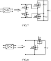
- FIG. 7 Another example of a specific structure of the non-isolated AC-DC conversion subunit is shown in FIG. 7 .
- a drain (D) of a MOS transistor S1 and a drain (D) of a S2 respectively serve as two input ends.
- a source (S) of the MOS transistor S1 is connected with a source (S) of the MOS transistor S2.
- the drain (D) of the S1 is connected with a source (S) of a MOS transistor S3 and a drain (S) of a MOS transistor S4.
- the drain (D) of the MOS transistor S2 is connected with a negative end of a capacitor C1 and a positive end of a capacitor C2.
- a drain (D) of the MOS transistor S3 is connected with a positive end of the capacitor C1 and a positive end of a capacitor C which may serve as a positive end of the output.
- a source (S) of the MOS transistor S4 is connected with a negative end of the capacitor C2 and a negative end of the capacitor C which may serve as a negative end of the output.
- the non-isolated DC-DC conversion subunit in FIG. 3 may specifically be a half-bridge circuit conversion subunit, and one example of a specific structure of the non-isolated DC-DC conversion subunit is shown in FIG. 8 .
- the non-isolated DC-DC conversion subunit may include two MOS transistors S1 and S2, and an output filter capacitor C.
- a drain (D) of a MOS transistor S1 and a source (S) of a MOS transistor S2 serve as one input end.
- a drain (D) of the MOS transistor S2 is connected with a positive end of the output filter capacitor C which may serve as a positive end of the output, and a source (S) of the MOS transistor S1 is connected with a negative end of the output filter capacitor C which may serve as a negative end of the output.
- the non-isolated DC-DC conversion subunit in FIG. 3 may specifically be a half bridge (boost converter) circuit conversion subunit, another example of a specific structure of the non-isolated DC-DC conversion subunit is shown in FIG. 9 .
- Differences in FIG. 9 from FIG. 8 are in that: the MOS transistor S2 in FIG. 8 is replaced with a diode D1, a drain of a MOS transistor S1 is connected with an anode of the diode D1, a cathode of the diode D1 is connected with a positive end of an output filter capacitor C which may serve as a positive end of the output, and the other connection manners are the same as those in FIG. 8 .
- the isolated DC-DC conversion subunit in FIG. 3 may specifically be an LLC half-bridge circuit conversion subunit or an LLC full-bridge circuit conversion subunit.
- the isolated DC-DC conversion subunit is the LLC half-bridge circuit conversion subunit
- FIG. 10 one example of a specific structure of the isolated DC-DC conversion subunit is shown in FIG. 10 .
- a drain (D) of a MOS transistor S1 is connected with one end of a capacitor C1 which may serve as one input end
- a source (S) of a MOS transistor S2 is connected with one end of a capacitor C2 which may serve as the other input end.
- a source (S) of the MOS transistor S1 is connected with a drain (S) of the MOS transistor S2 and one end of an inductor L, the other end of the inductor L is connected with one end of a primary side of a transformer T, and the other end of the primary side of the transformer T is connected with the other end of the inductor L.
- One end of a secondary side of the transformer T is connected with an anode of a diode D3 and a cathode of a diode D5, and the diodes D3 and D5 are connected in series to form a rectification bridge arm.
- the other end of the secondary side of the transformer T is connected with an anode of a diode D4 and a cathode of a diode D6, and the diodes D4 and D6 are connected in series to form another rectification bridge arm.
- a cathode of the diode D3 is connected with a cathode of the diode D4 and a positive end of an output filter capacitor C which may serve as a positive end of an output voltage
- an anode of the diode D5 is connected with an anode of the diode D6 and a negative end of the output filter capacitor C which may serve as a negative end of the output voltage.
- the isolated DC-DC conversion subunit in FIG. 3 may be specifically an LLC half-bridge circuit conversion subunit, and another example of a specific structure of the isolated DC-DC conversion subunit is shown in FIG. 11 , which is basically the same as that shown in FIG. 10 .
- FIG. 12 When the isolated DC-DC conversion subunit in FIG. 3 may be specifically an LLC half-bridge circuit conversion subunit, another example of a specific structure of the isolated DC-DC conversion subunit is shown in FIG. 12 .
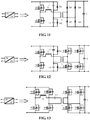
- FIG. 13 When the isolated DC-DC conversion subunit in FIG. 3 may be specifically an LLC full bridge circuit conversion subunit, one example of a specific structure of the isolated DC-DC conversion subunit is shown in FIG. 13 .
- a drain (D) of a MOS transistor S1 is connected with a drain (D) of a MOS transistor S3 which may serve as a positive input end
- a source of a MOS transistor S2 is connected with a source of a MOS transistor S4 which may serve as a negative input end.
- a source (S) of the MOS transistor S1 is connected with a drain (D) of the MOS transistor S2 and one end of an inductor L, and the S1 and the S2 are connected in series to form a bridge arm.
- a source (S) of the MOS transistor S3 is connected with a drain of the MOS transistor S4 and one end of a primary side of a transformer T, the S3 and the S4 are connected in series to form another bridge arm, the other end of the inductor L is connected with one end of a capacitor C1, and the other side of the capacitor C1 is connected with the other end of the primary side of the transformer T, that is, the inductor L, the capacitor C1 and the primary side of the transformer T are connected in series.
- One end of a secondary side of the transformer T is connected with a source (S) of a MOS transistor S5 and a drain (D) of a MOS transistor S7, and the S5 and the S7 are connected in series to form a bridge arm of an output rectifier.
- the other end of the secondary side of the transformer T is connected with a source (S) of a MOS transistor S6 and a drain (D) of a MOS transistor S8, and the S6 and the S8 are connected in series to form the other bridge arm of the output rectifier.
- a drain of the S5 is connected with a drain of the S6 and a positive end of an output filter capacitor C which may serve as a positive end of an output voltage
- a source of the S7 is connected with a source of the S8 and a negative end of the output filter capacitor C which may serve as a negative end of the output voltage.
- FIG. 14 shows a structure example diagram of a power conversion apparatus formed by connecting non-isolated AC-DC conversion subunits shown in FIG. 5 and isolated DC-DC conversion subunits shown in FIG. 13 in accordance with a connection manner shown in FIG. 3 .
- the AC-DC conversion subunit and the DC-DC conversion subunit shown in FIG. 4 to FIG. 13 may be combined and connected in accordance with a connection manner shown in FIG. 2 or FIG. 3 to obtain a power conversion apparatus.
- FIG. 2 or FIG. 3 shows a connection manner shown in FIG. 2 or FIG. 3 to obtain a power conversion apparatus.
- the present invention is not limited to implementation circuits of AC-DC and DC-DC conversion subunits shown in FIG. 4 to FIG. 13 , and in addition to the above AC-DC and DC-DC conversion subunits employing several circuit principles, AC-DC and DC-DC conversion subunits employing other circuit principles are also within the scope of the present invention.
- FIG. 15 shows a control timing sequence and an inductor current waveform of an AC-DC conversion subunit.
- Scell1, Scell2, ... ScellN in FIG. 15 are control waveforms of the corresponding AC-DC converters in FIG. 2
- iL is an inductor current waveform.
- each of the power conversion units includes a third conversion subunit, two output ends of the third conversion subunits of the power conversion units are respectively connected in parallel. Input ends of the third conversion subunits of the power conversion units are sequentially connected in series, and one input end of a third conversion subunit of the first power conversion unit and one input end of a third conversion subunit of the last power conversion unit are respectively connected with two ends of the alternating-current power supply.
- the input end of the third conversion subunit of the first power conversion unit is connected with the alternating-current power supply through the boost unit.
- the third conversion subunit may be an isolated AC-DC conversion subunit.
- the power conversion apparatus shown in FIG. 16 employs a monopolar isolated AC-DC conversion subunit and is composed of an input alternating-current power supply, a boost inductor L and isolated AC-DC conversion subunits.
- One end of the input current power supply is connected with one end of the boost inductor L, the other end of the boost inductor L is connected with one input end of a first monopolar isolated AC-DC conversion subunit, the other input end of the first monopolar isolated AC-DC conversion subunit is connected with one input end of a second monopolar isolated AC-DC conversion subunit, and so on, the other input end of a (N-1) h monopolar isolated AC-DC conversion subunit is connected with one input end of an N th monopolar isolated AC-DC conversion subunit, and the other input end of the N th monopolar isolated AC-DC conversion subunit is connected with the other end of the input alternating-current power supply. That is to say, inputs of the N monopolar isolated AC-DC conversion subunits are connected in series, and outputs of the N converters are connected in parallel.
- boost unit in the above examples and embodiments is illustrated by using one boost inductor as an example. It should be understood that the boost inductor in the present invention may also be divided into two or more inductors connecting in series in an input loop.
- the power conversion apparatus and the setting method of the power conversion apparatus provided by the embodiments of the present invention have the following beneficial effects.
- the voltage stress and the current stress on the switching device may be 1/n times those of the existing power conversion apparatus, so that switching and conduction losses may be reduced.
- an input inductance of a PFC unit is significantly reduced, thereby reducing the volume of the inductor and increasing the power density.
- the structure also makes the power conversion apparatus of the present invention have an automatic current sharing function and control on the power conversion apparatus be relatively simple and reliable.
Landscapes
- Engineering & Computer Science (AREA)
- Power Engineering (AREA)
- Dc-Dc Converters (AREA)
- Rectifiers (AREA)
Applications Claiming Priority (2)
| Application Number | Priority Date | Filing Date | Title |
|---|---|---|---|
| CN201510355472.3A CN105720840B (zh) | 2015-06-24 | 2015-06-24 | 功率变换装置及其设置方法 |
| PCT/CN2015/093447 WO2016206269A1 (zh) | 2015-06-24 | 2015-10-30 | 功率变换装置及其设置方法 |
Publications (2)
| Publication Number | Publication Date |
|---|---|
| EP3316469A1 true EP3316469A1 (de) | 2018-05-02 |
| EP3316469A4 EP3316469A4 (de) | 2019-03-06 |
Family
ID=56144790
Family Applications (1)
| Application Number | Title | Priority Date | Filing Date |
|---|---|---|---|
| EP15896158.1A Ceased EP3316469A4 (de) | 2015-06-24 | 2015-10-30 | Stromumwandlungsvorrichtung und konfigurationsverfahren dafür |
Country Status (4)
| Country | Link |
|---|---|
| US (1) | US10284093B2 (de) |
| EP (1) | EP3316469A4 (de) |
| CN (3) | CN105720840B (de) |
| WO (1) | WO2016206269A1 (de) |
Cited By (2)
| Publication number | Priority date | Publication date | Assignee | Title |
|---|---|---|---|---|
| EP3570421A4 (de) * | 2017-01-12 | 2020-11-11 | ZTE Corporation | Stromumwandlungsvorrichtung und steuerungsverfahren für die stromumwandlungsvorrichtung |
| EP4109724A1 (de) * | 2021-06-23 | 2022-12-28 | Compleo Charging Solutions AG | Gleichspannungswandler und betriebsverfahren für eine versorgungsstation |
Families Citing this family (29)
| Publication number | Priority date | Publication date | Assignee | Title |
|---|---|---|---|---|
| WO2018072209A1 (zh) * | 2016-10-21 | 2018-04-26 | 北京小米移动软件有限公司 | 充电方法及电子设备 |
| CN108574420B (zh) | 2017-03-08 | 2020-02-28 | 台达电子企业管理(上海)有限公司 | 电力电子变换单元及系统 |
| DE102017117888A1 (de) * | 2017-08-07 | 2019-02-07 | Infineon Technologies Austria Ag | Elektronische Schaltung mit einer Halbbrückenschaltung und einem Spannungsklemmelement |
| CN109713917A (zh) * | 2017-10-25 | 2019-05-03 | 中兴通讯股份有限公司 | 整流装置及整流控制方法 |
| CN109980913B (zh) * | 2017-12-27 | 2021-11-02 | 中兴通讯股份有限公司 | 开关电源,电压输出方法 |
| CN112088482A (zh) * | 2018-05-10 | 2020-12-15 | 株式会社东芝 | 直流变电系统 |
| CN109039052A (zh) * | 2018-10-17 | 2018-12-18 | 珠海泰通电气技术有限公司 | 基于pfc电路和谐振电路的单芯片控制电路 |
| CN112636613B (zh) | 2020-12-16 | 2022-09-16 | 矽力杰半导体技术(杭州)有限公司 | 交流-直流转换电路 |
| CN112615553B (zh) * | 2020-12-16 | 2023-09-08 | 矽力杰半导体技术(杭州)有限公司 | 交流-直流转换电路 |
| US12542496B2 (en) | 2021-02-18 | 2026-02-03 | Infineon Technologies Austria Ag | Hybrid power converter and power conversion |
| US11728721B2 (en) * | 2021-02-18 | 2023-08-15 | Infineon Technologies Austria Ag | Hybrid power converter and power conversion |
| CN113179012A (zh) * | 2021-03-16 | 2021-07-27 | 天地(常州)自动化股份有限公司 | 适用于矿用多级交流电压输入的直流稳压电源 |
| CN115347805B (zh) * | 2021-05-12 | 2026-04-03 | 台达电子企业管理(上海)有限公司 | 供电装置及其控制方法、三相供电系统及其控制方法 |
| CN113507226B (zh) * | 2021-06-25 | 2024-05-24 | 深圳市高益智能电气有限公司 | 一种三相整流变换器及其控制方法 |
| CN113394992B (zh) * | 2021-06-25 | 2024-05-17 | 深圳市高益智能电气有限公司 | 一种非隔离式三相升降压整流变换器及其控制方法 |
| CN113394991B (zh) * | 2021-06-25 | 2024-05-17 | 深圳市高益智能电气有限公司 | 一种非隔离式三相整流变换器及控制方法 |
| CN113394990B (zh) * | 2021-06-25 | 2024-05-17 | 深圳市高益智能电气有限公司 | 一种三相升降压整流变换器及其控制方法 |
| CN113507224B (zh) * | 2021-06-25 | 2024-05-24 | 深圳市高益智能电气有限公司 | 一种三相升降压整流变换器及控制方法 |
| CN113507225B (zh) * | 2021-06-25 | 2024-05-17 | 深圳市高益智能电气有限公司 | 一种非隔离式三相整流变换器及其控制方法 |
| EE202100018A (et) | 2021-06-30 | 2023-02-15 | Tallinna Tehnikaülikool | Jõuelektroonikaseade sisendina kasutatava vahelduvvoolu muundamiseks alalisvooluks |
| CN115589139A (zh) * | 2021-07-05 | 2023-01-10 | 台达电子企业管理(上海)有限公司 | 电源转换装置 |
| CN113659843B (zh) * | 2021-08-31 | 2023-08-11 | 湖北三江航天万峰科技发展有限公司 | 一种低开关损耗的dcdc变换器 |
| CN115940676A (zh) * | 2021-09-24 | 2023-04-07 | 台达电子企业管理(上海)有限公司 | 供电装置、三相供电系统及控制方法 |
| KR102838762B1 (ko) * | 2021-10-27 | 2025-07-24 | 컨템포러리 엠퍼렉스 테크놀로지 (홍콩) 리미티드 | 직병렬 전환 방법 및 장치, 전원전환회로와 전자기기 |
| CN118264131A (zh) * | 2022-12-28 | 2024-06-28 | 台达电子工业股份有限公司 | 中压电源转换系统与分散式中压电源转换系统 |
| EP4451537A1 (de) * | 2023-04-17 | 2024-10-23 | Delta Electronics (Shanghai) Co., Ltd. | Kaskadiertes leistungsumwandlungssystem und leistungsverteilungsverfahren dafür |
| CN119519424A (zh) * | 2023-08-23 | 2025-02-25 | 台达电子企业管理(上海)有限公司 | 中压输入直流供电系统 |
| CN117411307B (zh) * | 2023-10-23 | 2024-05-24 | 哈尔滨工业大学 | 适用于宽中频交直流电源系统的单级无桥pfc变换器 |
| CN119420182B (zh) * | 2024-10-28 | 2026-02-24 | 南京航空航天大学 | 一种实现位移电流均衡与抑制的集成llc结构 |
Family Cites Families (23)
| Publication number | Priority date | Publication date | Assignee | Title |
|---|---|---|---|---|
| JP3528921B2 (ja) * | 2001-08-29 | 2004-05-24 | サンケン電気株式会社 | スイッチング電源装置 |
| EP1750363A1 (de) * | 2005-08-03 | 2007-02-07 | Abb Research Ltd. | Mehrpegel- Wechselstrom/Gleichstromwandler für Traktionsanwendungen |
| TWI353709B (en) * | 2008-06-24 | 2011-12-01 | Elan Microelectronics Corp | Embedded bridge rectifier integrated with configur |
| CN101527520B (zh) | 2009-01-20 | 2011-06-15 | 华南理工大学 | 基于llc串联谐振的单级单相ac-dc变换器 |
| CN101917126B (zh) * | 2010-07-30 | 2012-08-15 | 浙江大学 | 一种多模块级联固态变压器均压均功率控制方法 |
| CN102055348A (zh) | 2010-12-24 | 2011-05-11 | 东南大学 | 一种用于配网的降压型电力电子变压器 |
| CN102751861A (zh) * | 2011-04-21 | 2012-10-24 | 艾默生网络能源系统北美公司 | 一种无桥功率因数校正电路 |
| US20130134935A1 (en) * | 2011-05-26 | 2013-05-30 | Electric Power Research Institute, Inc. | Medium voltage stand alone dc fast charger |
| CN102291019A (zh) * | 2011-07-22 | 2011-12-21 | 上海交通大学 | 全桥整流-直流推挽逆变的ac-dc变换器 |
| US20140153294A1 (en) * | 2012-12-05 | 2014-06-05 | Infineon Technologies Austria Ag | AC/DC Power Converter Arrangement |
| CN103051219A (zh) * | 2013-01-15 | 2013-04-17 | 中国矿业大学(北京) | 基于单级功率变换模块的级联式变流器 |
| EP2797217A1 (de) * | 2013-04-23 | 2014-10-29 | ABB Technology AG | Verteilte Steuerungen für einen Leistungselektronikwandler |
| CN103269177B (zh) * | 2013-04-27 | 2015-06-10 | 南京航空航天大学 | 一种分布式isop逆变器及其输入均压输出同幅值控制方法 |
| CN203327305U (zh) * | 2013-05-30 | 2013-12-04 | 中国民用航空总局第二研究所 | 一种无桥pfc+t型三电平逆变的变频调光器 |
| KR101399120B1 (ko) * | 2014-03-13 | 2014-05-27 | (주)티피에스 | 전력 변환 장치 |
| CN103986344B (zh) | 2014-05-30 | 2017-03-08 | 山东大学 | 单位功率因数单级ac‑dc隔离变换器的控制系统及控制方法 |
| CN104253548A (zh) * | 2014-07-10 | 2014-12-31 | 西南交通大学 | 一种无工频变压器的三电平电力电子牵引变压器 |
| EP3023291A1 (de) * | 2014-11-20 | 2016-05-25 | ABB Technology AG | Umrichtersystem zum elektrischen antreiben eines fahrzeuges |
| CN104539187A (zh) * | 2014-12-01 | 2015-04-22 | 东北电力大学 | 一种新型有源前端控制器拓扑结构 |
| CN204205997U (zh) * | 2014-12-04 | 2015-03-11 | 艾默生网络能源有限公司 | 一种三相整流电路及不间断电源 |
| US9758047B2 (en) * | 2015-02-13 | 2017-09-12 | Mcmaster University | Dual voltage charging system with an integrated active filter auxiliary power module |
| CN104702114B (zh) * | 2015-03-05 | 2017-07-18 | 清华大学 | 一种开关电容接入的高频链双向直流变压器及其控制方法 |
| US9793793B2 (en) * | 2015-06-26 | 2017-10-17 | Sharp Kabushiki Kaisha | Power factor correction circuit and power supply device |
-
2015
- 2015-06-24 CN CN201510355472.3A patent/CN105720840B/zh active Active
- 2015-06-24 CN CN201710522927.5A patent/CN107231097B/zh active Active
- 2015-06-24 CN CN201910257786.8A patent/CN110061636A/zh active Pending
- 2015-10-30 EP EP15896158.1A patent/EP3316469A4/de not_active Ceased
- 2015-10-30 WO PCT/CN2015/093447 patent/WO2016206269A1/zh not_active Ceased
- 2015-10-30 US US15/739,442 patent/US10284093B2/en active Active
Cited By (2)
| Publication number | Priority date | Publication date | Assignee | Title |
|---|---|---|---|---|
| EP3570421A4 (de) * | 2017-01-12 | 2020-11-11 | ZTE Corporation | Stromumwandlungsvorrichtung und steuerungsverfahren für die stromumwandlungsvorrichtung |
| EP4109724A1 (de) * | 2021-06-23 | 2022-12-28 | Compleo Charging Solutions AG | Gleichspannungswandler und betriebsverfahren für eine versorgungsstation |
Also Published As
| Publication number | Publication date |
|---|---|
| US10284093B2 (en) | 2019-05-07 |
| CN105720840A (zh) | 2016-06-29 |
| US20180183335A1 (en) | 2018-06-28 |
| CN105720840B (zh) | 2019-06-18 |
| CN107231097A (zh) | 2017-10-03 |
| CN107231097B (zh) | 2020-09-29 |
| CN110061636A (zh) | 2019-07-26 |
| EP3316469A4 (de) | 2019-03-06 |
| WO2016206269A1 (zh) | 2016-12-29 |
Similar Documents
| Publication | Publication Date | Title |
|---|---|---|
| US10284093B2 (en) | Power conversion apparatus and method for configuring the same | |
| Tang et al. | Hybrid switched-inductor converters for high step-up conversion | |
| CN102710152B (zh) | 一种高效率、快速响应的交流-直流电压转换电路 | |
| US20180269795A1 (en) | Bidirectional resonant conversion circuit and converter | |
| EP2276157A1 (de) | Stromwandler, Vorrichtung und Verfahren zum Überlappen der Leistungsfaktorberichtigungsschaltungen | |
| US9071161B2 (en) | Single stage PFC power supply | |
| US20120120697A1 (en) | Three-phase isolated rectifer with power factor correction | |
| JP5687498B2 (ja) | 電力変換システム | |
| EP3091652A1 (de) | Wandler mit bidirektionaler übertragung für hochspannung und hochleistung | |
| US10193464B2 (en) | DC-DC converter | |
| CN105141134A (zh) | 一种开关电源和控制该开关电源的方法 | |
| CN205725513U (zh) | 一种单相ac‑dc/dc‑ac双用电路及三相ac‑dc/dc‑ac双用电路 | |
| CN101399493A (zh) | 交直流整流装置 | |
| CN105612687B (zh) | 一种光伏应用场景下基于三态开关单元概念的dc-dc升压变换器 | |
| CN106169873A (zh) | 适用于高压或大电流输出的混合串并联全桥电路及其控制方法 | |
| JP2015070716A (ja) | Dc/dcコンバータ | |
| US9130472B2 (en) | High efficient single switch single stage power factor correction power supply | |
| CN107005171A (zh) | 电力变换单元 | |
| EP4113813A1 (de) | Leistungselektronisches gerät zum umwandeln von wechselstrom in gleichstrom | |
| CN203617902U (zh) | 集成降压-反激式高功率因数恒流电路及装置 | |
| CN103647448A (zh) | 集成降压-反激式高功率因数恒流电路及装置 | |
| Shin et al. | Analysis of LLC resonant converter with current-doubler rectification circuit | |
| US8665616B2 (en) | Near zero current-ripple inversion or rectification circuits | |
| CN103986360B (zh) | 高频隔离型升压式三电平逆变器 | |
| US20110080756A1 (en) | Modified zero voltage transition (zvt) full bridge converter and photovoltaic (pv) array using the same |
Legal Events
| Date | Code | Title | Description |
|---|---|---|---|
| STAA | Information on the status of an ep patent application or granted ep patent |
Free format text: STATUS: THE INTERNATIONAL PUBLICATION HAS BEEN MADE |
|
| PUAI | Public reference made under article 153(3) epc to a published international application that has entered the european phase |
Free format text: ORIGINAL CODE: 0009012 |
|
| STAA | Information on the status of an ep patent application or granted ep patent |
Free format text: STATUS: REQUEST FOR EXAMINATION WAS MADE |
|
| 17P | Request for examination filed |
Effective date: 20180122 |
|
| AK | Designated contracting states |
Kind code of ref document: A1 Designated state(s): AL AT BE BG CH CY CZ DE DK EE ES FI FR GB GR HR HU IE IS IT LI LT LU LV MC MK MT NL NO PL PT RO RS SE SI SK SM TR |
|
| AX | Request for extension of the european patent |
Extension state: BA ME |
|
| DAV | Request for validation of the european patent (deleted) | ||
| DAX | Request for extension of the european patent (deleted) | ||
| A4 | Supplementary search report drawn up and despatched |
Effective date: 20190131 |
|
| RIC1 | Information provided on ipc code assigned before grant |
Ipc: H02M 3/335 20060101ALI20190125BHEP Ipc: H02M 7/21 20060101AFI20190125BHEP Ipc: H02M 3/155 20060101ALI20190125BHEP Ipc: H02M 7/219 20060101ALI20190125BHEP |
|
| STAA | Information on the status of an ep patent application or granted ep patent |
Free format text: STATUS: EXAMINATION IS IN PROGRESS |
|
| 17Q | First examination report despatched |
Effective date: 20200123 |
|
| REG | Reference to a national code |
Ref country code: DE Ref legal event code: R003 |
|
| STAA | Information on the status of an ep patent application or granted ep patent |
Free format text: STATUS: THE APPLICATION HAS BEEN REFUSED |
|
| 18R | Application refused |
Effective date: 20210521 |