EP3316501A2 - Codage papier sale dans des réseaux sans fil - Google Patents
Codage papier sale dans des réseaux sans fil Download PDFInfo
- Publication number
- EP3316501A2 EP3316501A2 EP17195418.3A EP17195418A EP3316501A2 EP 3316501 A2 EP3316501 A2 EP 3316501A2 EP 17195418 A EP17195418 A EP 17195418A EP 3316501 A2 EP3316501 A2 EP 3316501A2
- Authority
- EP
- European Patent Office
- Prior art keywords
- wireless
- access device
- wireless access
- information
- channel
- Prior art date
- Legal status (The legal status is an assumption and is not a legal conclusion. Google has not performed a legal analysis and makes no representation as to the accuracy of the status listed.)
- Ceased
Links
Images


Classifications
-
- H—ELECTRICITY
- H04—ELECTRIC COMMUNICATION TECHNIQUE
- H04J—MULTIPLEX COMMUNICATION
- H04J11/00—Orthogonal multiplex systems, e.g. using WALSH codes
- H04J11/0023—Interference mitigation or co-ordination
- H04J11/0026—Interference mitigation or co-ordination of multi-user interference
- H04J11/003—Interference mitigation or co-ordination of multi-user interference at the transmitter
- H04J11/0033—Interference mitigation or co-ordination of multi-user interference at the transmitter by pre-cancellation of known interference, e.g. using a matched filter, dirty paper coder or Thomlinson-Harashima precoder
-
- H—ELECTRICITY
- H04—ELECTRIC COMMUNICATION TECHNIQUE
- H04L—TRANSMISSION OF DIGITAL INFORMATION, e.g. TELEGRAPHIC COMMUNICATION
- H04L25/00—Baseband systems
- H04L25/02—Details ; arrangements for supplying electrical power along data transmission lines
- H04L25/0202—Channel estimation
-
- H—ELECTRICITY
- H04—ELECTRIC COMMUNICATION TECHNIQUE
- H04L—TRANSMISSION OF DIGITAL INFORMATION, e.g. TELEGRAPHIC COMMUNICATION
- H04L1/00—Arrangements for detecting or preventing errors in the information received
- H04L1/0001—Systems modifying transmission characteristics according to link quality, e.g. power backoff
- H04L1/0009—Systems modifying transmission characteristics according to link quality, e.g. power backoff by adapting the channel coding
-
- H—ELECTRICITY
- H04—ELECTRIC COMMUNICATION TECHNIQUE
- H04L—TRANSMISSION OF DIGITAL INFORMATION, e.g. TELEGRAPHIC COMMUNICATION
- H04L1/00—Arrangements for detecting or preventing errors in the information received
- H04L1/004—Arrangements for detecting or preventing errors in the information received by using forward error control
- H04L1/0041—Arrangements at the transmitter end
-
- H—ELECTRICITY
- H04—ELECTRIC COMMUNICATION TECHNIQUE
- H04L—TRANSMISSION OF DIGITAL INFORMATION, e.g. TELEGRAPHIC COMMUNICATION
- H04L25/00—Baseband systems
- H04L25/02—Details ; arrangements for supplying electrical power along data transmission lines
- H04L25/03—Shaping networks in transmitter or receiver, e.g. adaptive shaping networks
- H04L25/03006—Arrangements for removing intersymbol interference
- H04L25/03343—Arrangements at the transmitter end
Definitions
- the present disclosure relates generally to wireless communication networks and, more particularly but not exclusively, to interference mitigation in wireless communication networks.
- these metro cells are placed in locations where they can be accessed by a large number of users, they have the potential to help offload significant amounts of traffic from the overloaded macro cells, thereby alleviating the capacity problems.
- deployment of such metro cells has the potential to offload traffic from the overloaded macro cells
- various deployment constraints associated with deploying such metro cells may limit the effectiveness of the metro cells in offloading traffic from the overloaded macro cells.
- the present disclosure generally discloses use of dirty paper coding in a wireless network.
- an apparatus includes a processor and a memory communicatively connected to the processor.
- the processor is configured to receive, by a first wireless access device from a wireless end device associated with the first wireless access device, feedback information including information indicative of channel estimate information for a channel between the wireless end device and the first wireless access device and information indicative of channel estimate information for a channel between the wireless end device and a second wireless access device.
- the processor is configured to receive, by the first wireless access device from the second wireless access device, information indicative of a transmit sequence to be transmitted by the second wireless access device using a set of wireless resources.
- the processor is configured to determine, by the first wireless access device using a dirty paper coding scheme and based on the feedback information and the information indicative of the transmit sequence to be transmitted by the second wireless access device, a transmit sequence for transmission by the first wireless access device toward the wireless end device using the set of wireless resources.
- the processor is configured to transmit the transmit sequence toward the wireless end device using the set of wireless resources.
- an apparatus includes a processor and a memory communicatively connected to the processor.
- the processor is configured to determine, by a wireless end device connected to a first wireless access device, feedback information including information indicative of channel estimate information for a channel between the wireless end device and the first wireless access device and information indicative of channel estimate information for a channel between the wireless end device and a second wireless access device.
- the processor is configured to send the feedback information from the wireless end device toward the first wireless access device.
- the processor is configured to receive, by the wireless end device from the first wireless access device, a wireless receive sequence.
- an apparatus in at least some embodiments, includes a processor and a memory communicatively connected to the processor.
- the processor is configured to receive, at a first wireless access device from a second wireless access device, a request for information indicative of a transmit sequence to be transmitted by the first wireless access device using a set of wireless resources.
- the processor is configured to send, from the first wireless access device toward the second wireless access device, a response including the information indicative of the transmit sequence to be transmitted by the first wireless access device using the set of wireless resources.
- the present disclosure generally discloses an interference mitigation capability.
- the present disclosure discloses use of dirty paper coding in a wireless communication network in order to mitigate interference in the wireless communication network.
- the wireless communication network may be a heterogeneous wireless communication network, where heterogeneity may be based on wireless access device technology type, wireless access device transmit power, or the like.
- the wireless communication network may be a heterogeneous wireless communication network including a first type of wireless access device (e.g., a small cell device, such as a metro cell, microcell, picocell, femtocell, or the like) and a second type of wireless access device (e.g., a large cell device, such as a macro cell), where the first type of wireless access device is configured to use dirty paper coding to mitigate interference from the second type of wireless access device.
- a first type of wireless access device e.g., a small cell device, such as a metro cell, microcell, picocell, femtocell, or the like
- a second type of wireless access device e.g., a large cell device, such as a macro cell
- FIG. 1 depicts an exemplary heterogeneous wireless communication system for illustrating use of dirty paper coding to mitigate interference of wireless access devices.
- the heterogeneous wireless communication system 100 may be based on any suitable wireless communications technologies.
- the heterogeneous wireless communication system 100 may include a primary communications system or capability and a secondary communications system or capability (e.g., to increase coverage, improve service, or the like).
- the primary and secondary communication systems or capabilities may be based on different wireless technologies or may be based on a common wireless technology.
- the primary communications system or capability may be a cellular-based communication system, such as a Third Generation (3G) Universal Mobile for Telecommunications System (UMTS) wireless communications system, a Fourth Generation (4G) Long Term Evolution (LTE) wireless communications system, a Fifth Generation (5G) wireless communications system, or the like, as well as various combinations thereof.
- the secondary communications system or capability may be based on various types of wireless communications technologies, such as small cell wireless communications technologies or the like. It is noted that the heterogeneous wireless communication system 100 may be based on other types of wireless communications technologies. It is further noted that the heterogeneity of heterogeneous wireless communication system 100 may be based on one or more of wireless access device technology type, wireless access device transmit power, or the like, as well as various combinations thereof.
- the heterogeneous wireless communication system 100 includes a set of wireless access devices (WADs) 110 and a wireless end device (WED) 120.
- WADs wireless access devices
- WED wireless end device
- the WADs 110 are wireless access devices configured to operate as points of wireless access for wireless end devices (illustratively, WED 120).
- the WADs include two WADs 110-L1 and 110-L2 (collectively, WADs 110-L) of a first WAD type and a WAD 110-S of a second WAD type.
- the WADs 110-L of the first WAD type may be large cell wireless access devices (e.g., macro cells).
- the WAD 110-S of the second WAD type may be a small cell wireless access device (e.g., a metro cell, a microcell, a picocell, a femtocell, or the like).
- the WADs 110 may be deployed at various geographic locations with respect to each other.
- the set of WADs 110 may include fewer or more WADs 110 (including fewer or more WAD 110-Ls or fewer or more WAD 110-Ss), that the WADs 110 may be arranged in various other arrangements with respect to each other, or the like, as well as various combinations thereof.
- the typical operation of wireless access devices in supporting wireless communications of wireless end devices will be understood.
- the WED 120 may be any suitable type of wireless device which may communicate wirelessly via WADs 110.
- the WED 120 may be configured to attach to one of the WADs 110 for wireless communication via that WAD 110.
- the WED 120 may be configured to receive information from a WAD 110 via a wireless downlink (DL) and to transmit information to a WAD 110 via a wireless uplink (UL).
- DL and UL may include various wireless resources configured to support communications of WED 120 and other WEDs (omitted for purposes of clarity), where the manner in which such wireless resources are defined and arranged may vary for different types of wireless communication networks (e.g., 4G LTE, 5G, or the like).
- the WED 120 may be a fixed wireless device or a mobile wireless device.
- WED 120 may be a wireless end device of a user (e.g., a smartphone, a tablet, a laptop computer, or the like), a wireless end device supporting automated communications (e.g., a wireless machine-type-communication (MTC) device, an Internet-of-Things (IoT) device, or the like), or the like.
- MTC wireless machine-type-communication
- IoT Internet-of-Things
- the WADs 110 and WED 120 may be configured to cooperate to support use of dirty paper coding techniques to mitigate interference within heterogeneous wireless communication system 100.
- the WAD 110-S includes a DPC interference mitigation element 111-S.
- the DPC interference mitigation element 111-S (and, thus, WAD 110-S) is configured to mitigate interference from one or more of the WADs 110-L when communicating with the WED 120.
- the DPC interference mitigation element 111-S may be configured to determine, for the WED 120, whether or not to apply DPC in order to mitigate interference from one or more of WADs 110-L when communicating with WED 120.
- the DPC interference mitigation element 111-S may be configured to determine whether or not to apply DPC when communicating with the WED 120 based on interference indicative information that is indicative as to the amount of interference that is experienced at WED 120 from the WADs 110-L.
- the DPC interference mitigation element 111-S may receive the interference indicative information for the WADs 110-L from the WED 120.
- the WED 120 may determine the interference indicative information of the WADs 110-L1 and 110-L2 based on processing of reference signals (RSs) received from the WADs 110-L1 and 110-L2, respectively.
- the WED 120 may determine and report the interference indicative information of the WADs 110-L in the form of one or more of Reference Signal Received Power (RSRP) values, Reference Signal Strength Indicator (RSSI) values, Reference Signal Received Quality (RSRQ) values, or the like.
- the DPC interference mitigation element 111-S may receive the interference indicative information for the WADs 110-L from the WED 120 and determine, for each of the WADs 110-L, whether or not interference of the respective WAD 110-L is to be mitigated based on DPC.
- the DPC interference mitigation element 111-S may determine, for a given WAD 110-L based on the interference indicative information for the given WAD 110-L, whether or not interference of the given WAD 110-L is to be mitigated based on DPC based on a determination as to whether interference experienced by the WED 120 from the given WAD 110-L is above a threshold. For example, for a given interference threshold, if interference experienced by the WED 120 from the WAD 110-L1 is above the threshold and interference experienced by the WED 120 from the WAD 110-L2 also is above the threshold, then DPC interference mitigation element 111-S may apply DPC for mitigation of the interference from WAD 110-L1 and WAD 110-L2 when transmitting to WED 120.
- DPC interference mitigation element 111-S may only apply DPC for mitigation of the interference from WAD 110-L1 when transmitting to WED 120.
- DPC interference mitigation element 111-S may determine that DPC does not need to be applied when transmitting to WED 120.
- the DPC interference mitigation element 111-S may be configured to dynamically activate and deactivate use of DPC, over various time scales (e.g., per resource block, per subframe, per frame, or the like) as the interference from the WADs 110-L1 and 110-L2 changes (e.g., as the interference indicative information that is determined and reported by the WED 120 for the WADs 110-L1 and 110-L2 changes).
- the DPC interference mitigation element 111-S also may be configured to determine whether or not interference of a given WAD 110-L is to be mitigated for the WED 120 based on DPC based on other information available to DPC interference mitigation element 111-S, such as whether or not the given WAD 110-L is scheduled to transmit when the WAD 110-S transmits to the WED 120 (e.g., even though the interference measured by the WED 120 for the given WAD 110-L is above an interference threshold, the DPC interference mitigation element 111-S may determine that mitigation of this interference of the given WAD 110-L is not necessary since the given WAD 110-L is not scheduled to transmit when the WAD 110-S transmits to the WED 120).
- the operation of the DPC interference mitigation element 111-S of the WAD 110-S in determining, for the WED 120, whether or not to apply DPC in order to mitigate interference from one or more of WADs 110-L when communicating with WED 120 may be further understood by way of reference to the DPC elements of FIGs. 2 and 3A - 3B and the method of FIG. 4 .
- the DPC interference mitigation element 111-S is configured to mitigate interference from the one or more of the WADs 110-L based on use of DPC, which may be further understood by way of reference to FIG. 2 .
- the DPC interference mitigation element 111-S of the WAD 110-S is configured to use DPC to mitigate interference from one or more of the WADs 110-L, when communicating with the WED 120, based on information that is received from the WED 120 for which interference mitigation is provided and based on information that is received from the one or more of the WADs 110-L for which interference is mitigated.
- the information received from the WED 120 for which interference mitigation is provided may include information which may be used for interference mitigation based on DPC (which also may be referred to herein as WED DPC information), such as information indicative of channel estimate information for a channel between the WED 120 and WAD 110-S, information indicative of channel estimate information for a channel(s) between the WED 120 and one or more WADs 110-L for which interference can be mitigated, a strength of the sum of noise and uncancelled interference at the WED 120, or the like, as well as various combinations thereof.
- DPC which also may be referred to herein as WED DPC information
- WED DPC information information indicative of channel estimate information for a channel between the WED 120 and WAD 110-S
- a strength of the sum of noise and uncancelled interference at the WED 120 or the like, as well as various combinations thereof.
- the information received from the one or more of the WADs 110-L for which interference is mitigated may include the transmit sequences to be sent by the one or more of the WADs 110-L for which interference is mitigated (during the time when WAD 110-S will be transmitting to the WED 120 and, therefore, also during the time for which interference mitigation is to be provided).
- the DPC interference mitigation element 111-S of the WAD 110-S may be configured to use various types of DPC schemes in order to mitigate interference from WADs 110-L.
- DPC interference mitigation element 111-S of the WAD 110-S may be configured to mitigate interference from WADs 110-L using a version of DPC that is referred to as Tomlinson-Harashima Precoding - Partial Interference Pre-subtraction (THP-PIP), which may be further understood by way of reference to FIGs. 2 and 3A - 3B .
- THP-PIP Tomlinson-Harashima Precoding - Partial Interference Pre-subtraction
- various other versions of DPC may be applied by the DPC interference mitigation element 111-S of the WAD 110-S in order to mitigate interference from WADs 110-L when communicating with WED 120.
- the operation of the DPC interference mitigation element 111-S of the WAD 110-S in mitigating interference when communicating with WED 120 may be further understood by way of reference to the DPC elements of FIGs. 2 and 3A - 3B and the method of FIG. 4 .
- the WADs 110-L1 and 110-L2 include DPC support elements 112-L1 and 112-L2 (collectively, DPC support elements 112-L), respectively.
- the DPC support elements 112-L1 and 112-L2 of the WADs 110-L1 and L2 are configured to provide the DPC interference mitigation element 111-S of the WAD 110-S with information for use in mitigating interference from WADs 110-L1 and 110-L2, respectively, based on DPC.
- the operation of the DPC support elements 112-L1 and 112-L2 of the WADs 110-L1 and L2 may be further understood by way of reference to the DPC elements of FIGs. 2 and 3A - 3B (e.g., in terms of DPC input information provided by wireless access devices whose interference is to be mitigated) and the method of FIG. 5 .
- the WED 120 includes a DPC support element 122.
- the DPC support element 122 of the WED 120 is configured to provide the DPC interference mitigation element 111-S of the WAD 110-S with information for use in mitigating interference from one or more of the WADs 110-L based on DPC.
- the operation of the DPC support element 122 of the WED 120 may be further understood by way of reference to the DPC elements of FIGs. 2 and 3A - 3B (e.g., in terms of DPC input information provided by a wireless device for which interference mitigation is to be provided) and the method of FIG. 6 .
- FIG. 2 depicts a high level block diagram of a dirty paper coding scheme for use by the small cell wireless access device of FIG. 1 .
- dirty paper coding is an information theoretic result that provides a mechanism for mitigating interference in wireless systems.
- DPC may be used to mitigate interference when a transmitter 210 transmits to a receiver 220.
- m denotes the information sequence to be transmitted by the transmitter 201 to the receiver 220 and x represents the transmit vector that is actually transmitted by the transmitter 201 to the receiver 220.
- the received vector r is corrupted by channel noise n and interference v .
- the key element of the DPC setting is that the interference v is known non-causally to the transmitter.
- the DPC result essentially states that, in the setting of FIG. 2 , it is possible to construct a coding scheme such that the error performance would be similar to the error performance that can be achieved over the same channel in the absence of the interference. In other words, if a certain transmit energy is needed to achieve some desired performance over the channel in the absence of the interference, it is possible to achieve the same performance at the same transmit energy level in the presence of the interference.
- This information theoretical result may be implemented in a number of ways, many of which are quite complex as they may be designed to approach the theoretical limit established by the DPC result. This makes many such schemes unsuited for implementation in a practical wireless system.
- THP-PIP Partial Interference Pre-subtraction
- LDPC low-density parity check
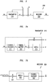
- FIGs. 3A - 3B depict high level block diagrams of a transmitter and a receiver configured to use a specific dirty paper coding scheme based on the dirty paper coding scheme of FIG. 2 .
- FIGs. 3A and 3B depict high level block diagrams of a transmitter 310 (which may correspond to the transmitter 210 of FIG. 2 ) and a receiver 320 (which may correspond to the receiver 220 of FIG. 2 ), respectively, that are configured to support use of THP-PIP dirty paper coding for communication via a wireless channel between the transmitter 310 and the receiver 320.
- the transmitter 310 may be implemented within WAD 110-S of FIG. 1 and the receiver 320 may be implemented within the WED 120 of FIG. 1 , thereby enabling WAD 110-S to mitigate interference from one or more of the WADs 120-L when transmitting to WED 120.
- FIG. 3A depicts a high-level block diagram of the transmitter 310 which, as noted above, is configured to support use of THP-PIP dirty paper coding to support mitigation of interference when transmitting to receiver 320.
- the transmitter 310 includes a channel encoder 311, a symbol mapper 312, and a mod- ⁇ element 313.
- a binary information sequence m is to be transmitted over the channel. This transmission is to take place in the presence of the interference vector v that is known non-causally to the transmitter.
- the channel also adds noise n to the transmitted signal.
- the channel encoder 311, using a suitable error correcting code encodes the information sequence m to produce the code word c.
- the symbol mapper 312 divides the code word c into groups of b bits, and maps these groups to points in a suitably chosen signal constellation, producing the code vector u .
- a commonly used value for ⁇ is P / (P + ⁇ 2 ) where P is the average per-symbol transmit energy and ⁇ 2 is the average per-symbol noise energy.
- FIG. 3B depicts a high-level block diagram of the receiver 320 which, as noted above, is configured to support use of THP-PIP dirty paper coding to support mitigation of interference when receiving from transmitter 310.
- the receiver 320 includes a multiplier 321, a mod- ⁇ element 322, and a channel decoder 323.
- the multiplier 321 multiplies the received vector r by the scaling factor ⁇ .
- the mod- ⁇ element 322 applies the modulo- ⁇ operation to the scaled vector ⁇ r and provides the resulting vector of symbols to the channel decoder 323 (which, it will be appreciated, is associated with the channel code that was used by the transmitter 310).
- the channel code is an LDPC code (e.g., LDPC codes are Linear Block Codes (LBCs) with a sparse parity check matrix H, and have been known to be highly efficient in that they perform close to the theoretical limit in AWGN channels); however, it will be appreciated that any suitable channel code may be used to construct a THP-PIP DPC scheme.
- the channel decoder 323 outputs the resulting vector of symbols m' .
- implementing DPC involves imposing an order - specifically, the wireless access devices whose interference is sought to be mitigated construct their transmit sequences first and, only after these transmit sequences have been determined, does the wireless access device that is implementing DPC determine its own transmit sequence.
- users associated with the latter i.e., the wireless access device that is implementing DPC
- benefit from interference reduction while users associated with the former i.e., wireless access devices that determine their transmit sequences first
- small cell devices may be configured to use DPC (e.g., THP-PIP DPC) in order to mitigate the interference experienced by their users from nearby large cell devices.
- DPC e.g., THP-PIP DPC
- at least some small cell devices use DPC to mitigate the interference that their users experience from the K strongest large cell devices, whereas the large cell devices communicate with their users without using DPC.
- the use of DPC in this manner may be further understood by considering the example of FIG. 4 .
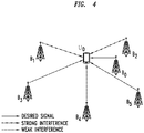
- FIG. 4 depicts an example of use of dirty paper coding by a given wireless access device to mitigate interference of other wireless access devices when the given wireless access device is communicating with a wireless end device.
- a wireless end device (which is denoted as U 0 ) is communicating with a wireless access device (which is denoted as B 0 ) within the presence of five other wireless access devices (which are denoted as B 1 , B 2 , B 3 , B 4 , and B 5 ).
- the signals transmitted by wireless access devices B 1 through B 5 constitute interference.
- wireless access device B 0 wants to implement DPC to mitigate these stronger interfering signals of wireless access devices B 1 and B 2 .
- the interference caused by wireless access devices B 3 , B 4 and B 5 is uncancelled interference.
- w 0 denote the M-dimensional filter vector used by wireless end device U 0 to obtain an estimate of the symbol transmitted by wireless access device B 0 .
- M denotes the number of receive antennas at the wireless end device U 0 .
- the quantity ⁇ 0 denotes the sum of thermal noise and uncancelled interference.
- the term x 0 corresponds to the transmit symbol " x " that the DPC encoder produces
- the sum " w 0 ⁇ h 1 x 1 / w 0 ⁇ h 0 + w 0 ⁇ h 2 x 2 / w 0 ⁇ h 0 " corresponds to the non-causally known interference " v " that the encoder tries to mitigate
- the term " w 0 ⁇ n ⁇ 0 / w 0 ⁇ h 0 " corresponds to the additive channel noise " n " that the encoder has no knowledge of except for its strength.
- the encoder at wireless access device B 0 needs to know the following information: (1) channel estimate information (i.e., the product w 0 ⁇ h 0 ) for the channel between the wireless end device U 0 (i.e., h 0 ) and itself and (2) channel estimate information (i.e., the products w 0 ⁇ h 1 and w 0 ⁇ h 2 ) for the channel(s) between the wireless end device U 0 and the wireless access device(s) whose interference is sought to be mitigated (i.e., h 1 and h 2 in this example), (3) the strength of the sum of the noise and uncancelled interference (i.e., w 0 ⁇ n ⁇ 0 ), and (4) the symbol(s) transmitted by the wireless access device(s) whose
- the wireless access device B 0 may obtain the channel estimate information (i.e., the products w 0 ⁇ h 0 , w 0 ⁇ h 1 , and w 0 ⁇ h 2 ) by either (1) receiving the channel estimate information (i.e., the products w 0 ⁇ h 0 , w 0 ⁇ h 1 , and w 0 ⁇ h 2 ) as feedback from the wireless end device U 0 (the products w 0 ⁇ h 0 , w 0 ⁇ h 1 , and w 0 ⁇ h 2 are computed by the wireless end device U 0 using the estimated channel information (i.e., h 0 , h 1 and h 2 ) and the filter vector w 0 ) or (2) receiving the estimated channel information (i.e., h 0 , h 1 and h 2 ) as feedback from the wireless end device U 0 , receiving the filter vector w 0 from the wireless end device U
- sending the channel estimate information i.e., the products w 0 ⁇ h 0 , w 0 ⁇ h 1 , and w 0 ⁇ h 2 , which are scalar quantities
- sending the estimated channel information i.e., h 0 , h 1 and h 2 , which are vectors
- the filter vector ( w 0 ) from the from the wireless end device U 0 to the wireless access device B 0 (such that wireless end device U 0 computes the products w 0 ⁇ h 0 , w 0 ⁇ h 1 , and w 0 ⁇ h 2 ) will reduce the load on the feedback channel from the wireless end device U 0 to the wireless access device B 0 .
- the wireless access device B 0 receives the strength of the sum of the noise and uncancelled interference, specifically the quantity w 0 ⁇ ⁇ 2 w 0 , where ⁇ 2 denotes the absolute mean square value of the sum of the noise and uncancelled interference at a receive antenna, as feedback from the wireless end device U 0 .
- the wireless access device B 0 obtains the symbol(s) transmitted by the wireless access device(s) whose interference is sought to be mitigated (i.e., x 1 and x 2 ) from the wireless access device(s) whose interference is sought to be mitigated, respectively.
- the wireless access device B 0 may obtain the symbol(s) transmitted by the wireless access device(s) whose interference is sought to be mitigated (i.e., x 1 and x 2 ) by (1) receiving the symbol(s) transmitted by the wireless access device(s) whose interference is sought to be mitigated (i.e., x 1 and x 2 ) from the wireless access device(s) whose interference is sought to be mitigated or (2) receiving information indicative of the symbol(s) transmitted by the wireless access devices whose interference is sought to be mitigated (e.g., receiving the raw information bits to be transmitted and receiving information about the Modulation and Coding Scheme (MCS) to be applied by the wireless access devices to transmit the raw information bits) and locally constructing the symbol(s) transmitted by the wireless access device(s) whose interference is sought to be mitigated (i.e., x 1 and x 2 ) based on the information indicative of the symbol(s) transmitted by the wireless access devices whose interference is sought to be mitigated.
- MCS Modulation and Coding
- the wireless access device B 0 may receive the feedback information from the wireless end device U 0 periodically or on demand (e.g., the wireless access device B 0 may request that the wireless end device U 0 provide the feedback information when the wireless access device B 0 is going to schedule a transmission to the wireless end device U 0 ), and may request the transmit symbol(s) from the wireless access devices whose interference is sought to be mitigated (i.e., x 1 and x 2 ) when the wireless access device B 0 is going to schedule a transmission to the wireless end device U 0 .
- FIG. 5 depicts an embodiment of a method for use by a small cell wireless access device to mitigate interference of a large cell wireless access device based on dirty paper coding. It will be appreciated that, although primarily presented as being performed serially, at least a portion of the blocks of method 500 may be performed contemporaneously or in a different order than as presented in FIG. 5 .
- method 500 begins.
- the small cell wireless access device receives, from a wireless end device associated with the small cell wireless access device, feedback information.
- the feedback information includes information indicative of channel estimate information for a channel between the wireless end device and the small cell wireless access device and information indicative of channel estimate information for a channel between the wireless end device and the large cell wireless access device.
- the information indicative of the channel estimate information for a channel may include (1) the channel estimate information itself (i.e., the products w 0 ⁇ h 0 and w 0 ⁇ h 1 ) or (2) the estimated channel information (i.e., h 0 and h 1 ) and the filter vector w 0 such that the channel estimate information (again, the products w 0 ⁇ h 0 and w 0 ⁇ h 1 ) may be computed.
- the feedback information also includes a strength of the sum of noise and uncancelled interference at the wireless end device.
- the feedback information may include other types of information.
- the small cell wireless access device receives, from the large cell wireless access device, information indicative of a transmit sequence to be transmitted by the large cell wireless access device using a set of wireless resources.
- the information indicative of a transmit sequence to be transmitted by the large cell wireless access device using a set of wireless resources may include (1) the transmit sequence itself (i.e., the symbol(s) to be transmitted by the large cell wireless access device or (2) information which may be used to construct the transmit sequence (e.g., receiving the raw information bits to be transmitted and receiving information about the MCS to be applied by the wireless access devices to transmit the raw information bits).
- the small cell wireless access device determines, using a dirty paper coding scheme and based on the feedback information and the information indicative of the transmit sequence to be transmitted by the large cell wireless access device, a transmit sequence for transmission by the small cell wireless access device toward the wireless end device using the set of wireless resources.
- the small cell wireless access device transmits the transmit sequence toward the wireless end device using the set of wireless resources.
- method 500 ends.
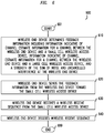
- FIG. 6 depicts an embodiment of a method for use by a wireless end device in supporting use of dirty paper coding by a small cell wireless access device to mitigate interference of a large cell wireless access device. It will be appreciated that, although primarily presented as being performed serially, at least a portion of the blocks of method 600 may be performed contemporaneously or in a different order than as presented in FIG. 6 .
- method 600 begins.
- the wireless end device determines feedback information including information indicative of channel estimate information for a channel between the wireless end device and the small cell wireless access device, information indicative of channel estimate information for a channel between the wireless end device and the large cell wireless access device, and a strength of the sum of noise and uncancelled interference at the wireless end device.
- the wireless end device sends the feedback information from the wireless end device toward the small cell wireless access device.
- the wireless end device receives a receive sequence from the small cell wireless access device via a set of wireless resources.
- the wireless receive sequence includes (1) a transmit sequence determined by the small cell wireless access device (using a dirty paper coding scheme based on the feedback information) and transmitted by the small cell wireless access device using the set of wireless resources, (2) interference (including uncancelled interference), and (3) noise.
- the wireless end device decodes the wireless receive sequence.
- the wireless end device decodes the wireless receive sequence to extract the information bits transmitted by the small cell wireless access device using the set of wireless resources.
- the wireless end device may then handle the information bits, extracted based on decoding of the wireless receive sequence, in various ways (e.g., storing the information bits, further propagating the information bits, processing the information bits, or the like, as well as various combinations thereof).
- method 600 ends.
- FIG. 7 depicts an embodiment of a method for use by a large cell wireless access device in supporting use of dirty paper coding by a small cell wireless access device to mitigate interference of the large cell wireless access device. It will be appreciated that, although primarily presented as being performed serially, at least a portion of the blocks of method 700 may be performed contemporaneously or in a different order than as presented in FIG. 7 .
- method 700 begins.
- the large cell wireless access device receives, from the small cell wireless access device, a request for information indicative of a transmit sequence to be transmitted by the large cell wireless access device using a set of wireless resources.
- the large cell wireless access device sends, toward the small cell wireless access device, a response including the information indicative of the transmit sequence to be transmitted by the large cell wireless access device using the set of wireless resources.
- method 700 ends.
- DPC while it may be applied in various contexts, is particularly well-suited for use within the context of a heterogeneous wireless network including large cell devices (e.g., macro cells) and small cell devices (e.g., metro cells).
- large cell devices e.g., macro cells
- small cell devices e.g., metro cells
- DPC may be applied to address major interference issues in co-channel heterogeneous wireless networks.
- use of DPC within this context is based on the metro cells receiving channel estimates from the wireless user devices that they are serving, a process that involves some delays.
- channels typically vary rapidly, which means that delays in reporting channel estimates can introduce significant errors in the channel estimates.
- metro cell users are typically static or exhibit low mobility, which means that their channels vary relatively slowly with time. As a result, even if there is a delay of a few milliseconds in reporting channel estimates, the channel estimates are likely to be quite accurate, thus making for a more effective DPC implementation.
- Various embodiments of the dirty paper coding capabilities may provide various advantages or potential advantages.
- various embodiments of the dirty paper coding capabilities may enable use of DPC in order to allow metro cells to mitigate most or all of the interference from macro cells without causing the macro cells to suffer loss of capacity.
- Various embodiments of the dirty paper coding capabilities may provide various other advantages or potential advantages.
- FIG. 8 depicts a high-level block diagram of a computer suitable for use in performing various functions presented herein.
- the computer 800 includes a processor 802 (e.g., a central processing unit (CPU), a processor having a set of processor cores, a processor core of a processor, or the like) and a memory 804 (e.g., a random access memory (RAM), a read only memory (ROM), or the like).
- the processor 802 and the memory 804 are communicatively connected.
- the computer 800 also may include a cooperating element 805.
- the cooperating element 805 may be a hardware device.
- the cooperating element 805 may be a process that can be loaded into the memory 804 and executed by the processor 802 to implement functions as discussed herein (in which case, for example, the cooperating element 805 (including associated data structures) can be stored on a non-transitory computer-readable storage medium, such as a storage device or other storage element (e.g., a magnetic drive, an optical drive, or the like)).
- the computer 800 also may include one or more input/output devices 806.
- the input/output devices 806 may include one or more of a user input device (e.g., a keyboard, a keypad, a mouse, a microphone, a camera, or the like), a user output device (e.g., a display, a speaker, or the like), one or more network communication devices or elements (e.g., an input port, an output port, a receiver, a transmitter, a transceiver, or the like), one or more storage devices (e.g., a tape drive, a floppy drive, a hard disk drive, a compact disk drive, or the like), or the like, as well as various combinations thereof.
- a user input device e.g., a keyboard, a keypad, a mouse, a microphone, a camera, or the like
- a user output device e.g., a display, a speaker, or the like
- network communication devices or elements e.g
- computer 800 of FIG. 8 may represent a general architecture and functionality suitable for implementing functional elements described herein, portions of functional elements described herein, or the like, as well as various combinations thereof.
- computer 800 may provide a general architecture and functionality that is suitable for implementing all or part of one or more of a WAD 110, a WED 120, or the like.
Landscapes
- Engineering & Computer Science (AREA)
- Computer Networks & Wireless Communication (AREA)
- Signal Processing (AREA)
- Power Engineering (AREA)
- Quality & Reliability (AREA)
- Mobile Radio Communication Systems (AREA)
Applications Claiming Priority (1)
| Application Number | Priority Date | Filing Date | Title |
|---|---|---|---|
| US15/288,052 US20180103480A1 (en) | 2016-10-07 | 2016-10-07 | Dirty paper coding in wireless networks |
Publications (2)
| Publication Number | Publication Date |
|---|---|
| EP3316501A2 true EP3316501A2 (fr) | 2018-05-02 |
| EP3316501A3 EP3316501A3 (fr) | 2018-07-25 |
Family
ID=60161924
Family Applications (1)
| Application Number | Title | Priority Date | Filing Date |
|---|---|---|---|
| EP17195418.3A Ceased EP3316501A3 (fr) | 2016-10-07 | 2017-10-09 | Codage papier sale dans des réseaux sans fil |
Country Status (2)
| Country | Link |
|---|---|
| US (1) | US20180103480A1 (fr) |
| EP (1) | EP3316501A3 (fr) |
Family Cites Families (3)
| Publication number | Priority date | Publication date | Assignee | Title |
|---|---|---|---|---|
| KR100961889B1 (ko) * | 2006-11-17 | 2010-06-09 | 삼성전자주식회사 | 다중 입력 다중 출력 시스템의 순차적 스케줄링 장치 및 방법 |
| KR101615116B1 (ko) * | 2009-07-13 | 2016-04-25 | 삼성전자주식회사 | 펨토 셀 또는 피코셀을 위한 프리코딩 방법 및 상기 방법을 사용하는 통신 시스템 |
| US8977268B2 (en) * | 2011-07-21 | 2015-03-10 | Alcatel Lucent | Methods and systems for controlling handovers in a co-channel network |
-
2016
- 2016-10-07 US US15/288,052 patent/US20180103480A1/en not_active Abandoned
-
2017
- 2017-10-09 EP EP17195418.3A patent/EP3316501A3/fr not_active Ceased
Non-Patent Citations (3)
| Title |
|---|
| HAITAO LI: "LDPC-LDGM Based Dirty Paper Coding Techniques for Multicell Cooperative Communication System", CIRCUITS, COMMUNICATIONS AND SYSTEMS, 2009. PACCS '09. PACIFIC-ASIA CONFERENCE ON, IEEE, PISCATAWAY, NJ, USA, 16 May 2009 (2009-05-16), pages 7 - 10, XP031526047, ISBN: 978-0-7695-3614-9 * |
| KARAKAYALI M K ET AL: "On the Maximum Common Rate Achievable in a Coordinated Network", COMMUNICATIONS, 2006. ICC '06. IEEE INTERNATIONAL CONFERENCE ON, IEEE, PI, 1 June 2006 (2006-06-01), pages 4333 - 4338, XP031026000, ISBN: 978-1-4244-0354-7, DOI: 10.1109/ICC.2006.255762 * |
| SHIH-CHUN LIN ET AL: "Practical Vector Dirty Paper Coding for MIMO Gaussian Broadcast Channels", IEEE JOURNAL ON SELECTED AREAS IN COMMUNICATIONS, IEEE SERVICE CENTER, PISCATAWAY, US, vol. 25, no. 7, 1 September 2007 (2007-09-01), pages 1345 - 1357, XP011191655, ISSN: 0733-8716, DOI: 10.1109/JSAC.2007.070908 * |
Also Published As
| Publication number | Publication date |
|---|---|
| EP3316501A3 (fr) | 2018-07-25 |
| US20180103480A1 (en) | 2018-04-12 |
Similar Documents
| Publication | Publication Date | Title |
|---|---|---|
| US11553364B2 (en) | System and method for reporting beam information | |
| US11166239B2 (en) | Mitigation of calibration errors | |
| KR102616419B1 (ko) | 무선 통신 시스템에서 안테나 구성에 기반한 빔 탐색 장치 및 방법 | |
| CN103404052B (zh) | 干扰协调方法、基站和用户设备 | |
| EP2984767B1 (fr) | Sélection de mode de transmission basée sur des conditions radio | |
| CN104025470B (zh) | 报告信道状态信息csi的方法、用户设备和基站 | |
| CN111869277B (zh) | 无线通信系统中参考信号功率增加的装置和方法 | |
| EP2462756B1 (fr) | Réduction des interférences provenant de stations de base voisines dominantes en interférence | |
| JP7657709B2 (ja) | 端末デバイスで実行される方法、端末デバイス、ネットワークデバイスで実行される方法、及びネットワークデバイス | |
| KR102369320B1 (ko) | 시분할 복신 기반의 무선 통신 시스템에서 셀 간 간섭을 제어하기 위한 장치 및 방법 | |
| US9479312B2 (en) | Method and apparatus for interference control | |
| US9247552B2 (en) | Allocation of resources in a communication system | |
| RU2506720C1 (ru) | Устройство и способ управления мощностью в восходящем канале | |
| WO2017167503A1 (fr) | Atténuation dynamique d'interférences en duplex par répartition temporelle dans un réseau sans fil | |
| US20170134105A1 (en) | Method, apparatus and computer program for antenna calibration | |
| US9414379B2 (en) | Wireless communication precoder determination | |
| CN112771787A (zh) | 针对csi码本的子带粒度的线性组合 | |
| US10750508B2 (en) | Channel state information feedback method, device, and system | |
| CN117956611A (zh) | 数据传输方法、数据接收方法、通信装置及存储介质 | |
| RU2573644C1 (ru) | Связь с множественным входом и множественным выходом (mimo) | |
| KR102278012B1 (ko) | 무선 통신 시스템에서 간섭 정렬을 위한 장치 및 방법 | |
| EP3011784B1 (fr) | Des procédés et des stations de base d'assistance à la planification d'un équipement utilisateur dans un réseau hétérogène | |
| WO2018228179A1 (fr) | Système et procédé d'indication d'autorisations de programmation | |
| EP3316501A2 (fr) | Codage papier sale dans des réseaux sans fil | |
| US20190200336A1 (en) | Method And Apparatus For Scheduling User Device In Multi-User Multi-Input Multi-Output Wireless System |
Legal Events
| Date | Code | Title | Description |
|---|---|---|---|
| PUAI | Public reference made under article 153(3) epc to a published international application that has entered the european phase |
Free format text: ORIGINAL CODE: 0009012 |
|
| STAA | Information on the status of an ep patent application or granted ep patent |
Free format text: STATUS: THE APPLICATION HAS BEEN PUBLISHED |
|
| AK | Designated contracting states |
Kind code of ref document: A2 Designated state(s): AL AT BE BG CH CY CZ DE DK EE ES FI FR GB GR HR HU IE IS IT LI LT LU LV MC MK MT NL NO PL PT RO RS SE SI SK SM TR |
|
| AX | Request for extension of the european patent |
Extension state: BA ME |
|
| PUAL | Search report despatched |
Free format text: ORIGINAL CODE: 0009013 |
|
| AK | Designated contracting states |
Kind code of ref document: A3 Designated state(s): AL AT BE BG CH CY CZ DE DK EE ES FI FR GB GR HR HU IE IS IT LI LT LU LV MC MK MT NL NO PL PT RO RS SE SI SK SM TR |
|
| AX | Request for extension of the european patent |
Extension state: BA ME |
|
| RIC1 | Information provided on ipc code assigned before grant |
Ipc: H04L 25/03 20060101ALI20180621BHEP Ipc: H04J 11/00 20060101AFI20180621BHEP |
|
| STAA | Information on the status of an ep patent application or granted ep patent |
Free format text: STATUS: REQUEST FOR EXAMINATION WAS MADE |
|
| 17P | Request for examination filed |
Effective date: 20190125 |
|
| RBV | Designated contracting states (corrected) |
Designated state(s): AL AT BE BG CH CY CZ DE DK EE ES FI FR GB GR HR HU IE IS IT LI LT LU LV MC MK MT NL NO PL PT RO RS SE SI SK SM TR |
|
| STAA | Information on the status of an ep patent application or granted ep patent |
Free format text: STATUS: EXAMINATION IS IN PROGRESS |
|
| 17Q | First examination report despatched |
Effective date: 20200221 |
|
| STAA | Information on the status of an ep patent application or granted ep patent |
Free format text: STATUS: THE APPLICATION HAS BEEN REFUSED |
|
| 18R | Application refused |
Effective date: 20220121 |