EP3316927B1 - Infusionssystem und verfahren zur schlaganfallbehandlung durch sonothrombolyse - Google Patents
Infusionssystem und verfahren zur schlaganfallbehandlung durch sonothrombolyse Download PDFInfo
- Publication number
- EP3316927B1 EP3316927B1 EP16733213.9A EP16733213A EP3316927B1 EP 3316927 B1 EP3316927 B1 EP 3316927B1 EP 16733213 A EP16733213 A EP 16733213A EP 3316927 B1 EP3316927 B1 EP 3316927B1
- Authority
- EP
- European Patent Office
- Prior art keywords
- syringe
- sonothrombolysis
- barrel
- infusion system
- microbubble
- Prior art date
- Legal status (The legal status is an assumption and is not a legal conclusion. Google has not performed a legal analysis and makes no representation as to the accuracy of the status listed.)
- Active
Links
Images


Classifications
-
- A—HUMAN NECESSITIES
- A61—MEDICAL OR VETERINARY SCIENCE; HYGIENE
- A61B—DIAGNOSIS; SURGERY; IDENTIFICATION
- A61B17/00—Surgical instruments, devices or methods
- A61B17/22—Implements for squeezing-off ulcers or the like on inner organs of the body; Implements for scraping-out cavities of body organs, e.g. bones; for invasive removal or destruction of calculus using mechanical vibrations; for removing obstructions in blood vessels, not otherwise provided for
-
- A—HUMAN NECESSITIES
- A61—MEDICAL OR VETERINARY SCIENCE; HYGIENE
- A61M—DEVICES FOR INTRODUCING MEDIA INTO, OR ONTO, THE BODY; DEVICES FOR TRANSDUCING BODY MEDIA OR FOR TAKING MEDIA FROM THE BODY; DEVICES FOR PRODUCING OR ENDING SLEEP OR STUPOR
- A61M5/00—Devices for bringing media into the body in a subcutaneous, intra-vascular or intramuscular way; Accessories therefor, e.g. filling or cleaning devices, arm-rests
- A61M5/14—Infusion devices, e.g. infusing by gravity; Blood infusion; Accessories therefor
- A61M5/142—Pressure infusion, e.g. using pumps
- A61M5/145—Pressure infusion, e.g. using pumps using pressurised reservoirs, e.g. pressurised by means of pistons
- A61M5/1452—Pressure infusion, e.g. using pumps using pressurised reservoirs, e.g. pressurised by means of pistons pressurised by means of pistons
- A61M5/1456—Pressure infusion, e.g. using pumps using pressurised reservoirs, e.g. pressurised by means of pistons pressurised by means of pistons with a replaceable reservoir comprising a piston rod to be moved into the reservoir, e.g. the piston rod is part of the removable reservoir
-
- A—HUMAN NECESSITIES
- A61—MEDICAL OR VETERINARY SCIENCE; HYGIENE
- A61N—ELECTROTHERAPY; MAGNETOTHERAPY; RADIATION THERAPY; ULTRASOUND THERAPY
- A61N7/00—Ultrasound therapy
-
- B—PERFORMING OPERATIONS; TRANSPORTING
- B01—PHYSICAL OR CHEMICAL PROCESSES OR APPARATUS IN GENERAL
- B01F—MIXING, e.g. DISSOLVING, EMULSIFYING OR DISPERSING
- B01F33/00—Other mixers; Mixing plants; Combinations of mixers
- B01F33/45—Magnetic mixers; Mixers with magnetically driven stirrers
- B01F33/452—Magnetic mixers; Mixers with magnetically driven stirrers using independent floating stirring elements
-
- B—PERFORMING OPERATIONS; TRANSPORTING
- B01—PHYSICAL OR CHEMICAL PROCESSES OR APPARATUS IN GENERAL
- B01F—MIXING, e.g. DISSOLVING, EMULSIFYING OR DISPERSING
- B01F33/00—Other mixers; Mixing plants; Combinations of mixers
- B01F33/50—Movable or transportable mixing devices or plants
- B01F33/501—Movable mixing devices, i.e. readily shifted or displaced from one place to another, e.g. portable during use
- B01F33/5011—Movable mixing devices, i.e. readily shifted or displaced from one place to another, e.g. portable during use portable during use, e.g. hand-held
- B01F33/50112—Movable mixing devices, i.e. readily shifted or displaced from one place to another, e.g. portable during use portable during use, e.g. hand-held of the syringe or cartridge type
-
- A—HUMAN NECESSITIES
- A61—MEDICAL OR VETERINARY SCIENCE; HYGIENE
- A61B—DIAGNOSIS; SURGERY; IDENTIFICATION
- A61B17/00—Surgical instruments, devices or methods
- A61B17/22—Implements for squeezing-off ulcers or the like on inner organs of the body; Implements for scraping-out cavities of body organs, e.g. bones; for invasive removal or destruction of calculus using mechanical vibrations; for removing obstructions in blood vessels, not otherwise provided for
- A61B2017/22082—Implements for squeezing-off ulcers or the like on inner organs of the body; Implements for scraping-out cavities of body organs, e.g. bones; for invasive removal or destruction of calculus using mechanical vibrations; for removing obstructions in blood vessels, not otherwise provided for after introduction of a substance
- A61B2017/22088—Implements for squeezing-off ulcers or the like on inner organs of the body; Implements for scraping-out cavities of body organs, e.g. bones; for invasive removal or destruction of calculus using mechanical vibrations; for removing obstructions in blood vessels, not otherwise provided for after introduction of a substance ultrasound absorbing, drug activated by ultrasound
-
- A—HUMAN NECESSITIES
- A61—MEDICAL OR VETERINARY SCIENCE; HYGIENE
- A61B—DIAGNOSIS; SURGERY; IDENTIFICATION
- A61B17/00—Surgical instruments, devices or methods
- A61B17/22—Implements for squeezing-off ulcers or the like on inner organs of the body; Implements for scraping-out cavities of body organs, e.g. bones; for invasive removal or destruction of calculus using mechanical vibrations; for removing obstructions in blood vessels, not otherwise provided for
- A61B2017/22082—Implements for squeezing-off ulcers or the like on inner organs of the body; Implements for scraping-out cavities of body organs, e.g. bones; for invasive removal or destruction of calculus using mechanical vibrations; for removing obstructions in blood vessels, not otherwise provided for after introduction of a substance
- A61B2017/22089—Gas-bubbles
-
- A—HUMAN NECESSITIES
- A61—MEDICAL OR VETERINARY SCIENCE; HYGIENE
- A61M—DEVICES FOR INTRODUCING MEDIA INTO, OR ONTO, THE BODY; DEVICES FOR TRANSDUCING BODY MEDIA OR FOR TAKING MEDIA FROM THE BODY; DEVICES FOR PRODUCING OR ENDING SLEEP OR STUPOR
- A61M2210/00—Anatomical parts of the body
- A61M2210/06—Head
- A61M2210/0693—Brain, cerebrum
-
- A—HUMAN NECESSITIES
- A61—MEDICAL OR VETERINARY SCIENCE; HYGIENE
- A61M—DEVICES FOR INTRODUCING MEDIA INTO, OR ONTO, THE BODY; DEVICES FOR TRANSDUCING BODY MEDIA OR FOR TAKING MEDIA FROM THE BODY; DEVICES FOR PRODUCING OR ENDING SLEEP OR STUPOR
- A61M2210/00—Anatomical parts of the body
- A61M2210/12—Blood circulatory system
-
- A—HUMAN NECESSITIES
- A61—MEDICAL OR VETERINARY SCIENCE; HYGIENE
- A61M—DEVICES FOR INTRODUCING MEDIA INTO, OR ONTO, THE BODY; DEVICES FOR TRANSDUCING BODY MEDIA OR FOR TAKING MEDIA FROM THE BODY; DEVICES FOR PRODUCING OR ENDING SLEEP OR STUPOR
- A61M5/00—Devices for bringing media into the body in a subcutaneous, intra-vascular or intramuscular way; Accessories therefor, e.g. filling or cleaning devices, arm-rests
- A61M5/14—Infusion devices, e.g. infusing by gravity; Blood infusion; Accessories therefor
- A61M5/1414—Hanging-up devices
- A61M5/1415—Stands, brackets or the like for supporting infusion accessories
-
- A—HUMAN NECESSITIES
- A61—MEDICAL OR VETERINARY SCIENCE; HYGIENE
- A61N—ELECTROTHERAPY; MAGNETOTHERAPY; RADIATION THERAPY; ULTRASOUND THERAPY
- A61N7/00—Ultrasound therapy
- A61N2007/0004—Applications of ultrasound therapy
- A61N2007/0021—Neural system treatment
-
- A—HUMAN NECESSITIES
- A61—MEDICAL OR VETERINARY SCIENCE; HYGIENE
- A61N—ELECTROTHERAPY; MAGNETOTHERAPY; RADIATION THERAPY; ULTRASOUND THERAPY
- A61N7/00—Ultrasound therapy
- A61N2007/0039—Ultrasound therapy using microbubbles
-
- B—PERFORMING OPERATIONS; TRANSPORTING
- B01—PHYSICAL OR CHEMICAL PROCESSES OR APPARATUS IN GENERAL
- B01F—MIXING, e.g. DISSOLVING, EMULSIFYING OR DISPERSING
- B01F2101/00—Mixing characterised by the nature of the mixed materials or by the application field
- B01F2101/2202—Mixing compositions or mixers in the medical or veterinary field
Definitions
- This invention relates to medical diagnostic ultrasound systems and, in particular, to ultrasound systems for sonothrombolysis stroke therapy.
- Ischemic stroke is one of the most debilitating disorders known to medicine.
- the blockage of the flow of blood to the brain can rapidly result in paralysis or death.
- Attempts to achieve recanalization through thrombolytic drug therapy such as treatment with tissue plasminogen activator (t-PA) has been reported to cause symptomatic intracerebral hemorrhage in a number of cases.
- t-PA tissue plasminogen activator
- Sonothrombolysis is an emerging treatment modality for stroke that uses ultrasound targeting of the site of the occluding clot, microbubbles in systemic circulation, and sometimes t-PA, to break up the fibrin structures that make up a typical clot, so as to try to restore normal blood flow to the occluded region in the brain.
- microbubbles are sometimes referred to as "vascular acoustic resonators," or VARs.
- VARs vascular acoustic resonators
- Such treatments typically use head-mounted, single-element transducer(s) or array transducers to deliver the ultrasound through the temporal bone, and operate in continuous or pulsed mode.
- International patent publication WO 2008/017997 (Browning et al.
- microbubble activity can in many instances aid in dissolving or breaking up the blood clot and return a nourishing flow of blood to the brain and other organs.
- microbubble activity can be used to deliver drugs encapsulated in microbubble shells, and well as microbubble-mediated sonothrombolysis.
- Clinical trials are ongoing in sonothrombolysis, using either a combination of ultrasound and t-PA, ultrasound and microbubbles, and/or ultrasound, t-PA, and microbubbles combined.
- a continuous flow of microbubbles is infused into the subject's blood stream from a syringe pump while ultrasound is delivered for upwards of an hour to assure that blood clots are completely lysed.
- This treatment regimen constantly replenishes the flow of microbubbles to the therapy site and thus requires a continuous infusion of a constant amount of microbubbles during the treatment period.
- a problem that has arisen during such lengthy periods of infusion is that the buoyancy of the microbubbles causes them to migrate to the top of the fluid in the syringe and stratify in levels of different microbubble concentration. This leads to different concentrations being infused into the body over time, which is not desirable, as it introduces treatment uncertainties.
- US 2009/012497 A1 discloses systems and methods of delivering a dilated slurry to a patient.
- US 2003/126914 A1 discloses a blood analyzer, blood sample handler, and a method for handling a blood sample.
- US 6,706,020 B1 discloses syringes and injectors incorporating magnetic fluid agitation devices.
- US 2002/154570 A1 discloses a method and apparatus for mixing liquid samples in a container using rotating magnetic fields.
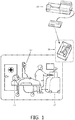
- FIGURE 1 A system which has been developed to address microbubble stratification is illustrated in FIGURE 1 .
- This illustration shows an ultrasound system which is delivering ultrasound to the brain of a patient through a headset 12 containing ultrasound transducers.
- a saline bag 14 would normally deliver a flow of fluid containing microbubbles to the vascular system of the patient through the tubing of an infusion set.
- the microbubble fluid is delivered from a syringe 16 which is operated by a specially modified syringe pump 18.
- the pump 18 includes a mechanism which gently rocks/rotates the syringe during the procedure, which alleviates the tendency of the microbubbles to stratify in the syringe.
- a sonothrombolysis infusion system delivers a constant supply of microbubbles from a syringe containing a microbubble solution and magnetic stirrer beads.
- a motorized magnetic stirrer Located in proximity to the syringe is a motorized magnetic stirrer. As the magnets of the stirrer move past the syringe they cause the magnetic beads to move in random or semi-random patterns of motion, continuously agitating the microbubble solution in the syringe and preventing microbubble stratification.
- the magnetic stirrer has a rotating rod with magnets on it, which can be mounted with the syringe by a retention mechanism of a syringe pump. The rotational speed of the magnetic stirrer can be varied so that its speed is sufficient to prevent microbubble stratification while maintaining the structural integrity of the microbubbles.
- the lower housing 20 contains a variable speed motor with gear train and a processor which controls the speed at which the motor rotates a worm gear 26 that advances a plate 28 mounted on two guide rods.
- the plate 28 advances as indicated by the arrow, pressing the plunger 32 of a syringe 16 into the barrel of the syringe (indicated at 16) and thereby expelling the fluid in the syringe at a controlled rate of flow.
- the barrel of the syringe rests in a groove in a syringe mount 22 during operation and is retained in place by a spring-loaded bar 25 that is positioned onto the syringe barrel by a release knob 24. With the syringe barrel held in place by the bar 25, the plate 28 advances to the right, pressing the plunger 32 into the syringe and expelling its fluid out the distal end of the syringe.
- FIGURE 3 illustrates in perspective a magnetic stirrer 40 constructed in accordance with the principles of the present invention.
- the stirrer comprises a frame with an enclosure 44 at one end which houses a motor and its reduction gearbox.
- the motor is a 6 volt motor with a drive shaft speed variable up to 200 rpm.
- the motor rotates an aluminum rod 42 having a bearing-mounted shaft 60.
- the rod is about 5cm in length, which is sufficient to oppose the barrel of a 30cc syringe.
- Affixed around the outer circumference of the rod 42 are a number of disc magnets 50.
- a groove 48 is formed in the base 46 of the stirrer 40 and extends along the entire length of the frame.
- the stirrer 40 is shown in use in a partially cross-sectional end view in FIGURE 4 when mounted on the barrel 34 of a syringe in a syringe pump.
- the barrel 34 of the syringe is seen to rest in a groove 36 in the syringe mount 22 of the syringe pump, and would normally be held in place by the spring-loaded bar 25.
- the stirrer 40 is positioned on top of the syringe barrel with the barrel extending partially into the groove 48 in the base 46 of the stirrer.
- the spring-loaded bar 25 extends through the stirrer, retaining stirrer base 46 in position on top of the syringe and the syringe in its proper position in the syringe pump.
- the rotating rod 42 and its magnets 50 are thus maintained in a substantially parallel alignment with the barrel of the syringe.
- the stirrer When the stirrer is actuated, its motor rotates the rod 42 as indicated by the curved arrow, and the magnets 50 on the circumference of the rod 42 are continually rotated over the syringe, moving the magnetic beads inside the syringe barrel 34 through magnetic attraction and repulsion.
- groove 48 in this implementation is seen to be a squared groove, the groove can also be a concave curved groove which contacts more of the surface of the syringe barrel when engaged.
- a squared groove 48 as shown has been found to be sufficient to engage the syringe and be held in place by the bar 25.
- FIGURE 5 is a side view of the assembly of FIGURE 4 .
- This illustration shows the magnetic beads 52 in the microbubble solution in the syringe barrel 34.
- the magnets 50 are quarter-inch diameter (0.64cm) Samarium cobalt disc magnets SC2512-500 available from Dura Magnetics, Inc. of Sylvania, OH, USA.
- the magnetic beads 52 are approximately 5mm in length and 2mm in diameter.
- Such beads are available from Cole-Parmer Instrument Company, LLC of Vernon Hills, IL, USA as part number 08545-02 .
- the magnets affixed to the stirrer rod 42 are powerful enough and pass close enough (approximately 5mm) to the syringe barrel 34 and the magnetic beads 52 to move/spin the magnetic beads located inside the syringe.
- the stirrer rod 42 is rotated by the stirrer motor, it rotates the magnets 50, which in turn move the magnetic beads 52 within the syringe, agitating the solution and thus preventing the microbubble solution from stratifying.
- this assembly easily stirs the microbubble solution without causing microbubble destruction.
- Other rotation speeds may be used, depending on factors such as the concentration of microbubbles, the number of beads used, and the size of the syringe. However, if the speed is too low, the microbubbles will still stratify; if the rotation speed is too high, the magnetic coupling between the magnets 50 on the stirrer rod 42 and the magnetic beads 52 separates, again resulting in insufficient stirring of the microbubble solution. Selective adjustment of the rotational speed is often required.
- microbubble solutions are usually packaged in a vial with a rubber membrane as are other injectable liquids.
- the microbubble solution may be aspirated from such a vial by use of a 20 gauge or larger needle attached to the distal end of the syringe which pierces the membrane to withdraw the microbubble solution.
- microbubble solution is required for continuous infusion during a one hour sonothrombolysis treatment. This equates to a flow rate of 0.83 ml/min.
- the amount of microbubble solution in the syringe should be 50 ml plus an additional amount to enable priming of the infusion tube set, plus a further amount to account for the inability to fully depress the plunger to the end of the syringe barrel due to the presence of the magnetic beads in the barrel of the syringe.
- this additional amount of microbubble solution is about 10 ml, bringing the total amount of solution required to about 60 ml in many cases.
- the length of the tubing is kept as short as possible between the distal end of the syringe and the catheterized infusion site.
- the tubing length is restricted to 30cm or less. Tubing length of 10cm or less has been found to result in no significant microbubble stratification in the infusion tubing. A significant rate of flow will also help prevent stratification.
- sterile magnetic beads In use, several sterile magnetic beads, at least two or more, are placed in the barrel of a syringe and the plunger inserted as far as it can go into the barrel.
- a 12 gauge or larger needle is attached to the distal end of the syringe and used to pierce the membrane of a vial of microbubble solution.
- the solution is drawn into syringe by retracting the plunger until the required amount of solution, generally 50 ml or more, fills the syringe.
- the syringe needle is pointed upward and the plunger depressed slightly to expel any air in the barrel.
- the needle is removed and infusion tubing leading to a transcutaneous catheter is attached to the distal end of the syringe.
- the syringe is placed in the groove of the syringe mount of a syringe pump and the magnetic stirrer placed on the barrel of the syringe.
- the spring-loaded retention bar of the syringe pump is inserted through the stirrer and springs downward to hold the stirrer and syringe in place on the pump and the stirrer is turned on. If necessary, its speed is adjusted so that stratification is prevented without significant microbubble destruction.
- the syringe pump is actuated to prime the tubing, if necessary, by injecting microbubble solution (or saline) into the tubing. After priming the catheter is inserted into a vein of the patient.
- the syringe pump is actuated to begin the injection of a continuous, controlled amount of microbubble solution into the patient while ultrasound is administered to the patient transcranially.
- An injection of t-PA can be added to the solution if desired via another infusion pump and connected tubing.
- the stirrer turned off, and the catheter withdrawn from the vein of the patient.
Landscapes
- Health & Medical Sciences (AREA)
- Life Sciences & Earth Sciences (AREA)
- Public Health (AREA)
- General Health & Medical Sciences (AREA)
- Veterinary Medicine (AREA)
- Animal Behavior & Ethology (AREA)
- Engineering & Computer Science (AREA)
- Biomedical Technology (AREA)
- Nuclear Medicine, Radiotherapy & Molecular Imaging (AREA)
- Heart & Thoracic Surgery (AREA)
- Surgery (AREA)
- Vascular Medicine (AREA)
- Chemical & Material Sciences (AREA)
- Chemical Kinetics & Catalysis (AREA)
- Molecular Biology (AREA)
- Radiology & Medical Imaging (AREA)
- Anesthesiology (AREA)
- Hematology (AREA)
- Medical Informatics (AREA)
- Orthopedic Medicine & Surgery (AREA)
- Infusion, Injection, And Reservoir Apparatuses (AREA)
Claims (8)
- Infusionssystem durch Sonothrombolyse, umfassend:eine Spritzenpumpe;eine Spritze mit einem Zylinder, der konfiguriert ist, um eine Mikrobläschenlösung zu halten, die eine Vielzahl von Magnetkügelchen enthält, wobei die Spritze an der Spritzenpumpe montiert ist; undeinen Magnetrührer; wobei der Magnetrührer in der Nähe des Spritzenzylinders montiert ist,dadurch gekennzeichnet, dass der Magnetrührer einen rotierenden Stab mit einer Vielzahl an Magneten darauf umfasst.
- Infusionssystem durch Sonothrombolyse nach Anspruch 1, wobei sich ein Außenumfang des rotierenden Stabs in der Nähe des Spritzenzylinders befindet.
- Infusionssystem durch Sonothrombolyse nach Anspruch 2, wobei der rotierende Stab im Wesentlichen parallel zum Spritzenzylinder ist, wenn der Magnetrührer in der Nähe des Spritzenzylinders montiert ist.
- Infusionssystem durch Sonothrombolyse nach Anspruch 2, wobei der Magnetrührer zudem einen Motor umfasst, der mit dem Stab gekoppelt ist, um den Stab mit einer wählbaren Drehgeschwindigkeit zu drehen.
- Infusionssystem durch Sonothrombolyse nach Anspruch 4, wobei die wählbare Drehgeschwindigkeit im Bereich von 60-200 U/min liegt.
- Infusionssystem durch Sonothrombolyse nach Anspruch 4, wobei die wählbare Drehgeschwindigkeit weniger als 100 U/min beträgt.
- Infusionssystem durch Sonothrombolyse nach Anspruch 1, wobei die Spritzenpumpe zudem
eine Rückhaltestange umfasst, die die Spritze in einer Montageposition an der Spritzenpumpe zurückhält,
wobei der Magnetrührer in der Nähe des Spritzenzylinders durch die Rückhaltestange gehalten wird. - Infusionssystem durch Sonothrombolyse nach Anspruch 7, wobei die Rückhaltestange zudem eine federbelastete Rückhaltestange umfasst; und
wobei die Spritzenpumpe zudem einen Freigabeknopf umfasst, der mit der federbelasteten Rückhaltestange gekoppelt ist.
Applications Claiming Priority (2)
| Application Number | Priority Date | Filing Date | Title |
|---|---|---|---|
| US201562186606P | 2015-06-30 | 2015-06-30 | |
| PCT/IB2016/053731 WO2017001980A1 (en) | 2015-06-30 | 2016-06-23 | Infusion system and method for sonothrombolysis stroke treatment |
Publications (2)
| Publication Number | Publication Date |
|---|---|
| EP3316927A1 EP3316927A1 (de) | 2018-05-09 |
| EP3316927B1 true EP3316927B1 (de) | 2020-03-25 |
Family
ID=56289551
Family Applications (1)
| Application Number | Title | Priority Date | Filing Date |
|---|---|---|---|
| EP16733213.9A Active EP3316927B1 (de) | 2015-06-30 | 2016-06-23 | Infusionssystem und verfahren zur schlaganfallbehandlung durch sonothrombolyse |
Country Status (3)
| Country | Link |
|---|---|
| US (1) | US10695078B2 (de) |
| EP (1) | EP3316927B1 (de) |
| WO (1) | WO2017001980A1 (de) |
Families Citing this family (2)
| Publication number | Priority date | Publication date | Assignee | Title |
|---|---|---|---|---|
| AU2019270182B2 (en) * | 2018-05-18 | 2024-11-21 | Bard Peripheral Vascular, Inc. | Microsphere containment systems and methods |
| GB2642542A (en) * | 2024-07-12 | 2026-01-14 | Protondx Ltd | A sample treatment apparatus |
Family Cites Families (11)
| Publication number | Priority date | Publication date | Assignee | Title |
|---|---|---|---|---|
| US4741732A (en) * | 1984-05-10 | 1988-05-03 | The University Of Melbourne | Open-loop control of drug infusion |
| US6726650B2 (en) * | 1997-12-04 | 2004-04-27 | Bracco Research S.A. | Automatic liquid injection system and method |
| DE19840536A1 (de) * | 1998-08-28 | 2000-03-09 | Schering Ag | Mit Ultraschallkontrastmittel gefüllte Spritze mit einer magnetischen Bewegungsvorrichtung |
| AU2001285239A1 (en) * | 2000-09-19 | 2002-04-02 | Kendell Simm | Hypodermic needle holder |
| US6467946B1 (en) | 2001-04-24 | 2002-10-22 | Dade Microscan Inc. | Method and apparatus for mixing liquid samples in a container using rotating magnetic fields |
| US6880384B2 (en) * | 2001-06-26 | 2005-04-19 | Radiometer Medical A/S | Blood analyzer, blood sample handler, and method for handling a blood sample |
| WO2004069153A2 (en) * | 2003-01-27 | 2004-08-19 | Medrad, Inc. | Apparatus, system and method for generating bubbles on demand |
| US9630028B2 (en) | 2006-08-11 | 2017-04-25 | Koninklijke Philips N.V. | Ultrasound system for cerebral blood flow imaging and microbubble-enhanced blood clot lysis |
| US8382704B2 (en) | 2006-12-29 | 2013-02-26 | Medrad, Inc. | Systems and methods of delivering a dilated slurry to a patient |
| GB201303806D0 (en) * | 2013-03-04 | 2013-04-17 | 3P Innovation Ltd | A mixing apparatus |
| US20150131405A1 (en) * | 2013-11-08 | 2015-05-14 | Xerox Corporation | Magnetic mixing for continuous latex preparation |
-
2016
- 2016-06-23 EP EP16733213.9A patent/EP3316927B1/de active Active
- 2016-06-23 WO PCT/IB2016/053731 patent/WO2017001980A1/en not_active Ceased
- 2016-06-23 US US15/735,981 patent/US10695078B2/en active Active
Non-Patent Citations (1)
| Title |
|---|
| None * |
Also Published As
| Publication number | Publication date |
|---|---|
| WO2017001980A1 (en) | 2017-01-05 |
| EP3316927A1 (de) | 2018-05-09 |
| US10695078B2 (en) | 2020-06-30 |
| US20180185040A1 (en) | 2018-07-05 |
Similar Documents
| Publication | Publication Date | Title |
|---|---|---|
| JP7686700B2 (ja) | 体液交換システム | |
| US8257338B2 (en) | Medical microbubble generation | |
| CA2433205A1 (en) | Drug delivery, bodily fluid drainage, and biopsy device with enhanced ultrasonic visibility | |
| US8308741B2 (en) | Systems and methods for automatically inserting a needle into a living subject | |
| US9814827B2 (en) | Systems and methods of delivering a dilated slurry to a patient | |
| JP5614911B2 (ja) | 貫通制限手段を有する、物質の皮内送達のためのニードル | |
| CN1177625C (zh) | 输送装置及对其进行定向的方法 | |
| CN109152583A (zh) | 用于溶解血栓和传送药剂的系统和方法 | |
| JP2004510650A (ja) | 懸濁剤供給用装置およびその供給方法 | |
| WO2004069153A2 (en) | Apparatus, system and method for generating bubbles on demand | |
| EP1613390A2 (de) | Fluid-abgabesysteme, vorrichtungen und verfahren zur abgabe von gefährlichen fluids | |
| CA2584638C (en) | Medical device for generating transient bubbles | |
| EP3316927B1 (de) | Infusionssystem und verfahren zur schlaganfallbehandlung durch sonothrombolyse | |
| JP2004041484A (ja) | 薬液注入装置 | |
| WO2025193525A1 (en) | Catheter with force-sensitive coating | |
| CN113577407A (zh) | 一种用于介入治疗的遥控精确液体注射/抽吸控制装置 | |
| WO2021123953A1 (en) | Injection pump needle mechanics | |
| HK40017068A (en) | Fluid exchange system | |
| HK40017068B (en) | Fluid exchange system |
Legal Events
| Date | Code | Title | Description |
|---|---|---|---|
| STAA | Information on the status of an ep patent application or granted ep patent |
Free format text: STATUS: THE INTERNATIONAL PUBLICATION HAS BEEN MADE |
|
| PUAI | Public reference made under article 153(3) epc to a published international application that has entered the european phase |
Free format text: ORIGINAL CODE: 0009012 |
|
| STAA | Information on the status of an ep patent application or granted ep patent |
Free format text: STATUS: REQUEST FOR EXAMINATION WAS MADE |
|
| 17P | Request for examination filed |
Effective date: 20180130 |
|
| AK | Designated contracting states |
Kind code of ref document: A1 Designated state(s): AL AT BE BG CH CY CZ DE DK EE ES FI FR GB GR HR HU IE IS IT LI LT LU LV MC MK MT NL NO PL PT RO RS SE SI SK SM TR |
|
| AX | Request for extension of the european patent |
Extension state: BA ME |
|
| DAV | Request for validation of the european patent (deleted) | ||
| DAX | Request for extension of the european patent (deleted) | ||
| GRAP | Despatch of communication of intention to grant a patent |
Free format text: ORIGINAL CODE: EPIDOSNIGR1 |
|
| STAA | Information on the status of an ep patent application or granted ep patent |
Free format text: STATUS: GRANT OF PATENT IS INTENDED |
|
| INTG | Intention to grant announced |
Effective date: 20191024 |
|
| GRAS | Grant fee paid |
Free format text: ORIGINAL CODE: EPIDOSNIGR3 |
|
| GRAA | (expected) grant |
Free format text: ORIGINAL CODE: 0009210 |
|
| STAA | Information on the status of an ep patent application or granted ep patent |
Free format text: STATUS: THE PATENT HAS BEEN GRANTED |
|
| RAP1 | Party data changed (applicant data changed or rights of an application transferred) |
Owner name: KONINKLIJKE PHILIPS N.V. |
|
| AK | Designated contracting states |
Kind code of ref document: B1 Designated state(s): AL AT BE BG CH CY CZ DE DK EE ES FI FR GB GR HR HU IE IS IT LI LT LU LV MC MK MT NL NO PL PT RO RS SE SI SK SM TR |
|
| REG | Reference to a national code |
Ref country code: GB Ref legal event code: FG4D |
|
| REG | Reference to a national code |
Ref country code: DE Ref legal event code: R096 Ref document number: 602016032523 Country of ref document: DE |
|
| REG | Reference to a national code |
Ref country code: AT Ref legal event code: REF Ref document number: 1247831 Country of ref document: AT Kind code of ref document: T Effective date: 20200415 Ref country code: IE Ref legal event code: FG4D |
|
| REG | Reference to a national code |
Ref country code: DE Ref legal event code: R084 Ref document number: 602016032523 Country of ref document: DE |
|
| REG | Reference to a national code |
Ref country code: GB Ref legal event code: 746 Effective date: 20200519 |
|
| PG25 | Lapsed in a contracting state [announced via postgrant information from national office to epo] |
Ref country code: NO Free format text: LAPSE BECAUSE OF FAILURE TO SUBMIT A TRANSLATION OF THE DESCRIPTION OR TO PAY THE FEE WITHIN THE PRESCRIBED TIME-LIMIT Effective date: 20200625 Ref country code: FI Free format text: LAPSE BECAUSE OF FAILURE TO SUBMIT A TRANSLATION OF THE DESCRIPTION OR TO PAY THE FEE WITHIN THE PRESCRIBED TIME-LIMIT Effective date: 20200325 Ref country code: RS Free format text: LAPSE BECAUSE OF FAILURE TO SUBMIT A TRANSLATION OF THE DESCRIPTION OR TO PAY THE FEE WITHIN THE PRESCRIBED TIME-LIMIT Effective date: 20200325 |
|
| PG25 | Lapsed in a contracting state [announced via postgrant information from national office to epo] |
Ref country code: HR Free format text: LAPSE BECAUSE OF FAILURE TO SUBMIT A TRANSLATION OF THE DESCRIPTION OR TO PAY THE FEE WITHIN THE PRESCRIBED TIME-LIMIT Effective date: 20200325 Ref country code: LV Free format text: LAPSE BECAUSE OF FAILURE TO SUBMIT A TRANSLATION OF THE DESCRIPTION OR TO PAY THE FEE WITHIN THE PRESCRIBED TIME-LIMIT Effective date: 20200325 Ref country code: SE Free format text: LAPSE BECAUSE OF FAILURE TO SUBMIT A TRANSLATION OF THE DESCRIPTION OR TO PAY THE FEE WITHIN THE PRESCRIBED TIME-LIMIT Effective date: 20200325 Ref country code: BG Free format text: LAPSE BECAUSE OF FAILURE TO SUBMIT A TRANSLATION OF THE DESCRIPTION OR TO PAY THE FEE WITHIN THE PRESCRIBED TIME-LIMIT Effective date: 20200625 Ref country code: GR Free format text: LAPSE BECAUSE OF FAILURE TO SUBMIT A TRANSLATION OF THE DESCRIPTION OR TO PAY THE FEE WITHIN THE PRESCRIBED TIME-LIMIT Effective date: 20200626 |
|
| REG | Reference to a national code |
Ref country code: NL Ref legal event code: MP Effective date: 20200325 |
|
| REG | Reference to a national code |
Ref country code: LT Ref legal event code: MG4D |
|
| PG25 | Lapsed in a contracting state [announced via postgrant information from national office to epo] |
Ref country code: NL Free format text: LAPSE BECAUSE OF FAILURE TO SUBMIT A TRANSLATION OF THE DESCRIPTION OR TO PAY THE FEE WITHIN THE PRESCRIBED TIME-LIMIT Effective date: 20200325 |
|
| PG25 | Lapsed in a contracting state [announced via postgrant information from national office to epo] |
Ref country code: RO Free format text: LAPSE BECAUSE OF FAILURE TO SUBMIT A TRANSLATION OF THE DESCRIPTION OR TO PAY THE FEE WITHIN THE PRESCRIBED TIME-LIMIT Effective date: 20200325 Ref country code: CZ Free format text: LAPSE BECAUSE OF FAILURE TO SUBMIT A TRANSLATION OF THE DESCRIPTION OR TO PAY THE FEE WITHIN THE PRESCRIBED TIME-LIMIT Effective date: 20200325 Ref country code: IS Free format text: LAPSE BECAUSE OF FAILURE TO SUBMIT A TRANSLATION OF THE DESCRIPTION OR TO PAY THE FEE WITHIN THE PRESCRIBED TIME-LIMIT Effective date: 20200725 Ref country code: SK Free format text: LAPSE BECAUSE OF FAILURE TO SUBMIT A TRANSLATION OF THE DESCRIPTION OR TO PAY THE FEE WITHIN THE PRESCRIBED TIME-LIMIT Effective date: 20200325 Ref country code: PT Free format text: LAPSE BECAUSE OF FAILURE TO SUBMIT A TRANSLATION OF THE DESCRIPTION OR TO PAY THE FEE WITHIN THE PRESCRIBED TIME-LIMIT Effective date: 20200818 Ref country code: LT Free format text: LAPSE BECAUSE OF FAILURE TO SUBMIT A TRANSLATION OF THE DESCRIPTION OR TO PAY THE FEE WITHIN THE PRESCRIBED TIME-LIMIT Effective date: 20200325 Ref country code: SM Free format text: LAPSE BECAUSE OF FAILURE TO SUBMIT A TRANSLATION OF THE DESCRIPTION OR TO PAY THE FEE WITHIN THE PRESCRIBED TIME-LIMIT Effective date: 20200325 Ref country code: EE Free format text: LAPSE BECAUSE OF FAILURE TO SUBMIT A TRANSLATION OF THE DESCRIPTION OR TO PAY THE FEE WITHIN THE PRESCRIBED TIME-LIMIT Effective date: 20200325 |
|
| REG | Reference to a national code |
Ref country code: AT Ref legal event code: MK05 Ref document number: 1247831 Country of ref document: AT Kind code of ref document: T Effective date: 20200325 |
|
| REG | Reference to a national code |
Ref country code: DE Ref legal event code: R097 Ref document number: 602016032523 Country of ref document: DE |
|
| PG25 | Lapsed in a contracting state [announced via postgrant information from national office to epo] |
Ref country code: AT Free format text: LAPSE BECAUSE OF FAILURE TO SUBMIT A TRANSLATION OF THE DESCRIPTION OR TO PAY THE FEE WITHIN THE PRESCRIBED TIME-LIMIT Effective date: 20200325 Ref country code: DK Free format text: LAPSE BECAUSE OF FAILURE TO SUBMIT A TRANSLATION OF THE DESCRIPTION OR TO PAY THE FEE WITHIN THE PRESCRIBED TIME-LIMIT Effective date: 20200325 Ref country code: MC Free format text: LAPSE BECAUSE OF FAILURE TO SUBMIT A TRANSLATION OF THE DESCRIPTION OR TO PAY THE FEE WITHIN THE PRESCRIBED TIME-LIMIT Effective date: 20200325 Ref country code: IT Free format text: LAPSE BECAUSE OF FAILURE TO SUBMIT A TRANSLATION OF THE DESCRIPTION OR TO PAY THE FEE WITHIN THE PRESCRIBED TIME-LIMIT Effective date: 20200325 Ref country code: ES Free format text: LAPSE BECAUSE OF FAILURE TO SUBMIT A TRANSLATION OF THE DESCRIPTION OR TO PAY THE FEE WITHIN THE PRESCRIBED TIME-LIMIT Effective date: 20200325 |
|
| REG | Reference to a national code |
Ref country code: CH Ref legal event code: PL |
|
| PLBE | No opposition filed within time limit |
Free format text: ORIGINAL CODE: 0009261 |
|
| STAA | Information on the status of an ep patent application or granted ep patent |
Free format text: STATUS: NO OPPOSITION FILED WITHIN TIME LIMIT |
|
| PG25 | Lapsed in a contracting state [announced via postgrant information from national office to epo] |
Ref country code: PL Free format text: LAPSE BECAUSE OF FAILURE TO SUBMIT A TRANSLATION OF THE DESCRIPTION OR TO PAY THE FEE WITHIN THE PRESCRIBED TIME-LIMIT Effective date: 20200325 |
|
| 26N | No opposition filed |
Effective date: 20210112 |
|
| PG25 | Lapsed in a contracting state [announced via postgrant information from national office to epo] |
Ref country code: LU Free format text: LAPSE BECAUSE OF NON-PAYMENT OF DUE FEES Effective date: 20200623 |
|
| REG | Reference to a national code |
Ref country code: BE Ref legal event code: MM Effective date: 20200630 |
|
| PG25 | Lapsed in a contracting state [announced via postgrant information from national office to epo] |
Ref country code: IE Free format text: LAPSE BECAUSE OF NON-PAYMENT OF DUE FEES Effective date: 20200623 Ref country code: LI Free format text: LAPSE BECAUSE OF NON-PAYMENT OF DUE FEES Effective date: 20200630 Ref country code: CH Free format text: LAPSE BECAUSE OF NON-PAYMENT OF DUE FEES Effective date: 20200630 |
|
| PG25 | Lapsed in a contracting state [announced via postgrant information from national office to epo] |
Ref country code: SI Free format text: LAPSE BECAUSE OF FAILURE TO SUBMIT A TRANSLATION OF THE DESCRIPTION OR TO PAY THE FEE WITHIN THE PRESCRIBED TIME-LIMIT Effective date: 20200325 Ref country code: BE Free format text: LAPSE BECAUSE OF NON-PAYMENT OF DUE FEES Effective date: 20200630 |
|
| PG25 | Lapsed in a contracting state [announced via postgrant information from national office to epo] |
Ref country code: TR Free format text: LAPSE BECAUSE OF FAILURE TO SUBMIT A TRANSLATION OF THE DESCRIPTION OR TO PAY THE FEE WITHIN THE PRESCRIBED TIME-LIMIT Effective date: 20200325 Ref country code: MT Free format text: LAPSE BECAUSE OF FAILURE TO SUBMIT A TRANSLATION OF THE DESCRIPTION OR TO PAY THE FEE WITHIN THE PRESCRIBED TIME-LIMIT Effective date: 20200325 Ref country code: CY Free format text: LAPSE BECAUSE OF FAILURE TO SUBMIT A TRANSLATION OF THE DESCRIPTION OR TO PAY THE FEE WITHIN THE PRESCRIBED TIME-LIMIT Effective date: 20200325 |
|
| PG25 | Lapsed in a contracting state [announced via postgrant information from national office to epo] |
Ref country code: MK Free format text: LAPSE BECAUSE OF FAILURE TO SUBMIT A TRANSLATION OF THE DESCRIPTION OR TO PAY THE FEE WITHIN THE PRESCRIBED TIME-LIMIT Effective date: 20200325 Ref country code: AL Free format text: LAPSE BECAUSE OF FAILURE TO SUBMIT A TRANSLATION OF THE DESCRIPTION OR TO PAY THE FEE WITHIN THE PRESCRIBED TIME-LIMIT Effective date: 20200325 |
|
| PGFP | Annual fee paid to national office [announced via postgrant information from national office to epo] |
Ref country code: FR Payment date: 20230622 Year of fee payment: 8 Ref country code: DE Payment date: 20230627 Year of fee payment: 8 |
|
| PGFP | Annual fee paid to national office [announced via postgrant information from national office to epo] |
Ref country code: GB Payment date: 20230620 Year of fee payment: 8 |
|
| REG | Reference to a national code |
Ref country code: DE Ref legal event code: R119 Ref document number: 602016032523 Country of ref document: DE |
|
| GBPC | Gb: european patent ceased through non-payment of renewal fee |
Effective date: 20240623 |
|
| PG25 | Lapsed in a contracting state [announced via postgrant information from national office to epo] |
Ref country code: DE Free format text: LAPSE BECAUSE OF NON-PAYMENT OF DUE FEES Effective date: 20250101 |
|
| PG25 | Lapsed in a contracting state [announced via postgrant information from national office to epo] |
Ref country code: FR Free format text: LAPSE BECAUSE OF NON-PAYMENT OF DUE FEES Effective date: 20240630 |
|
| PG25 | Lapsed in a contracting state [announced via postgrant information from national office to epo] |
Ref country code: GB Free format text: LAPSE BECAUSE OF NON-PAYMENT OF DUE FEES Effective date: 20240623 |