EP3316945B1 - Élément de protection d'aiguille à double fonctionnalité articulée - Google Patents
Élément de protection d'aiguille à double fonctionnalité articulée Download PDFInfo
- Publication number
- EP3316945B1 EP3316945B1 EP16818346.5A EP16818346A EP3316945B1 EP 3316945 B1 EP3316945 B1 EP 3316945B1 EP 16818346 A EP16818346 A EP 16818346A EP 3316945 B1 EP3316945 B1 EP 3316945B1
- Authority
- EP
- European Patent Office
- Prior art keywords
- needle
- shield
- guard
- needle shield
- hinge
- Prior art date
- Legal status (The legal status is an assumption and is not a legal conclusion. Google has not performed a legal analysis and makes no representation as to the accuracy of the status listed.)
- Active
Links
Images

Classifications
-
- A—HUMAN NECESSITIES
- A61—MEDICAL OR VETERINARY SCIENCE; HYGIENE
- A61M—DEVICES FOR INTRODUCING MEDIA INTO, OR ONTO, THE BODY; DEVICES FOR TRANSDUCING BODY MEDIA OR FOR TAKING MEDIA FROM THE BODY; DEVICES FOR PRODUCING OR ENDING SLEEP OR STUPOR
- A61M5/00—Devices for bringing media into the body in a subcutaneous, intra-vascular or intramuscular way; Accessories therefor, e.g. filling or cleaning devices, arm-rests
- A61M5/178—Syringes
- A61M5/31—Details
- A61M5/32—Needles; Details of needles pertaining to their connection with syringe or hub; Accessories for bringing the needle into, or holding the needle on, the body; Devices for protection of needles
- A61M5/3205—Apparatus for removing or disposing of used needles or syringes, e.g. containers; Means for protection against accidental injuries from used needles
- A61M5/321—Means for protection against accidental injuries by used needles
- A61M5/3216—Caps placed transversally onto the needle, e.g. pivotally attached to the needle base
-
- A—HUMAN NECESSITIES
- A61—MEDICAL OR VETERINARY SCIENCE; HYGIENE
- A61D—VETERINARY INSTRUMENTS, IMPLEMENTS, TOOLS, OR METHODS
- A61D7/00—Devices or methods for introducing solid, liquid, or gaseous remedies or other materials into or onto the bodies of animals
-
- A—HUMAN NECESSITIES
- A61—MEDICAL OR VETERINARY SCIENCE; HYGIENE
- A61M—DEVICES FOR INTRODUCING MEDIA INTO, OR ONTO, THE BODY; DEVICES FOR TRANSDUCING BODY MEDIA OR FOR TAKING MEDIA FROM THE BODY; DEVICES FOR PRODUCING OR ENDING SLEEP OR STUPOR
- A61M2250/00—Specially adapted for animals
Definitions
- the present invention relates to a needle guard arranged to shield a needle from accidental contact with an animal or human such as patients and medical personnel.
- a pointed hollow needle is well known in the medical art for the administration of solutions or suspensions, such as medicaments, to a human or animal.
- solutions or suspensions such as medicaments
- the needle After puncturing of the skin and introduction of the needle tip the content of a syringe typically connected to the rear part of the needle is administered to the human or animal through the hollow needle.
- the needle has then done its duty and is withdrawn from the human or animal.
- an unprotected withdrawn needle constitutes a serious health hazard due to the fact that it may be contaminated with e.g. infectious agents originating from the patient's blood or other body fluids, in combination with the needle tip's inherent ability to easily penetrate skin.
- the medical personnel who are handling the withdrawn needle may acquire an undesirable disease, e.g. HIV or hepatitis, if they accidentally contact the needle with their skin.
- an undesirable disease e.g. HIV or hepatitis
- US 5,603,699 discloses a needle guard assembly comprising a mounting base and a jacket assembly pivotally mounted on the mounting base.
- the jacket assembly comprises a shield member, a lever member and activating means.
- the activating means are adapted for movement of the jacket assembly from a retracted position to a closed position around a needle.
- Disadvantages of this needle guard assembly include its complicated construction and inherent bulkiness. The former being associated with a large cost of production and the latter with at least an increased volume of bio-hazard waste. Furthermore, a multi-part needle guard such as this is associated with a relatively high cost of production and difficulties in its assembly.
- EP 0 887 082 A2 describes a safety cover which is pivoting around a point near the needle hub.
- the safety cover is folded forwards and to the side over the needle after injection and withdrawal of the needle from the skin.
- the pivoting safety cover is provided with a locking hook mechanism that mates with the needle hub upon locking, which in turn demands the manual push of the pivoting safety cover to be sufficient to overcome the resistance of the locking hook mechanism.
- This force needs to be relatively high, which increases the risk of the user not to lock the safety cover in e.g. a stressful situation.
- the safety cover may thus be left unlocked which results in a potential health hazard.
- the needle tip is not secured until the pivoting arm has been manually pushed against the needle shaft, before which the user still is susceptible to stung/cut.
- Additional safety covers of the prior art with a construction similar to the construction of the safety cover described in EP 0 887 082 A2 may comprise an additional looking hook mechanism that locks around the shaft of the needle, or only a looking hook mechanism that locks around the shaft of the needle.
- the force needed to overcome the resistance of the locking hook mechanism needs, also in these cases, to be quite high. This force is also applied on the needle. The needle may therefore be broken or lost from the cooperation with the hub. This presents a danger to the user, since the user may be stung or cut on the broken/lost needle.
- None of above described needle guards protects the needle immediately after withdrawal of the needle from the skin. Hence, a user may accidently come into contact with the needle tip in the time span between withdrawal of the needle and activation of the needle guard by the user. It is well known that the patient often moves during the painful administration of medicaments through the needle, i.e. when the content of the connected syringe is injected. Such movement by the patient may result in involuntary withdrawal of the needle, leaving it exposed and without protection from accidental contact. It is estimated that 20 to 25% of all accidents in which medical personnel are injured by the needle occur during the actual injection of the syringe content.
- WO 2013/006134 discloses a needle guard for shielding of a needle after use which addresses the drawbacks associated with the above described needle guards.
- the needle guard of WO 2013/006134 occupies a large volume when the guard is packaged, transported and stored prior to its use by medical personnel on humans or animals. This increases the costs associated with each of the steps prior to the end use.
- the present invention seeks to mitigate, alleviate, circumvent or eliminate at least one of the above identified deficiencies in the art.
- the invention is as defined in independent claim 1. Accordingly, the invention relates to a needle guard for protecting a human or animal from accidental contact with a needle connected to said needle guard, comprising:
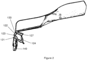
- Figs. 1 and 2 illustrate a needle guard 100.
- the needle guard 100 broadly comprises four parts in the form of (i) a needle shield 110, (ii) a hinge structure 120, (iii) a needle shield hinge 133, and (iv) a mounting base 140.
- the needle shield 110 may be shaped as a rod, arm or other similar elongated structure that is able to receive and enclose a needle during use as will be described further below.
- An elongated slot 115 is formed longitudinally on the needle shield 110 for allowing sideways entry and acceptance of the needle.
- the ratio between the width of the elongated slot 115 to the diameter of the needle may be 10 to 1, 5 to 1, or preferably 2 to 1.
- the lower end portion of the needle shield 110 may be in contact with the mounting base 140 such that the entire length of the needle is enclosed by the needle shield 110.
- the needle shield 110 also comprises a needle lock 117 in the slot 115 which securely engages the needle and therefore the needle shield 110 in the closed position during use so that it may not revert to the open position.
- the needle lock 117 may comprise one or several locking members extending from or forming a part of the needle shield 110 for example, a hook-shaped extension. If desired, the needle shield 110 may be provided with suitable color indicators correlating with differing needle sizes.
- the needle shield 110 also comprises an aperture 129 for fixedly receiving a spring plate 127 of the hinge structure 120 during use as will be described below.
- the needle shield 110 is connected to the mounting base 140 through hinge structure 120.
- the hinge structure 120 comprises V-shaped spring member 124 connected to the mounting base 140 and a spring plate 127 connected to the spring member 124.
- the spring member 124 comprises a press member 125 for applying pressure to the hinge structure 120 by way of a user's finger or thumb during injection of a medicament.
- the hinge structure 120 further comprises a toggle joint 121 adjacent to the mounting base 140, a leg portion 122 adjacent to a needle shield hinge 133, and a toggle joint knee 123 between the toggle joint 121 and the leg portion 122.
- This arrangement provides for a dead-center toggle function in the hinge structure 120 that forces the needle shield 110 to one of two oppositely-disposed positions being the open position (shown in Fig. 2 ) or the closed position.
- the open position the needle shield 110 is remotely positioned from the needle on the mounting base 140 so that the needle is exposed and is able to penetrate the skin of a patient.
- the closed position the needle is enclosed and protected by the needle shield 110.
- the hinge structure 120 snaps the needle shield 110 into the closed position.
- the dead-center position of the hinge structure 120 corresponds to a dead-centre angle between the longitudinal extensions of the needle and the needle shield 110.
- the needle shield 110 strives toward the closed position thereby receiving the needle in slot 115. If the angle is greater than the dead-centre angle, the needle shield 110 strives toward the open position ( Fig. 2 ).
- the dead-centre angle may be in the range of 45 to 170°, such as 80 to 120° or 90 to 110°.
- a longer leg portion 122 increases the dead-center angle. Moving the point of attachment of spring member 124 further above the point of attachment of the toggle joint 121 decreases the dead-center angle.
- a needle shield hinge 133 is located adjacent to needle shield 110 and the leg portion 122 of hinge structure 120.
- the needle shield hinge 133 permits pivoting of the needle shield 110 relative to the hinge structure 120. This occurs independently from pivoting of the needle shield 110 relative to the mounting base 140 between open and closed positions as described above in relation to the hinge structure 120.
- Needle shield hinge 133 may be formed by molding together thin sections of the leg portion 122 and needle shield 110. Alternatively, a pin (not shown) may be used to form hinge 133. Pivoting of the needle shield 110 about needle hinge 133 occurs freely by moving the needle shield 110 to any desired position or angle.
- the dual hinge functionality of the needle guard 100 is important.
- the hinge structure 120 provides the first hinge function in the needle guard 100 by permitting pivotal movement of the needle shield 110 in relation to the mounting base 140. This first hinge function is relied upon during and after injection of a medicament into a human or animal patient by the user of the needle guard 100 and prevents accidental contact of the patient and the user with the needle.
- the second hinge function in the needle guard 100 is provided by needle hinge 133 and allows for movement of the needle shield 110 to a more desirable position during packaging or storage prior to use of the needle guard 100.
- the mounting base 140 comprises a needle hub bore 141 extending through the mounting base 140 for securely fitting to and mating with a needle or a needle hub such that the needle extends distally from the mounting base 140.
- the inner surface of the needle hub bore 141 has a size and shape corresponding to the outer surface of the needle or needle hub to achieve a secure fit and avoid movement of the needle.
- the needle hub bore 141 may be a conically shaped hole with a diameter that narrows in the same direction as the extension of the needle.
- the needle hub bore 141 may be provided with longitudinal recesses that correspond and mate with the longitudinal protrusions of standard needle hubs.
- the mounting base 140 is not movable in relation to a needle arranged on the mounting base 140.
- Use of the needle guard 100 may involve the following steps:
- the needle guard 100 may be made of a thermoplastic, plastic or polymeric material such as polypropylene (PP), high-density polyethylene (HDPE), polyamide (PA) and acrylnitrile-butadiene-styrene copolymer (ABS). These materials allow for manufacturing the needle guard 100 as a monolithically formed single article which minimizes manufacturing costs.
- the thermoplastic, plastic or polymeric material will be selected to achieve sufficient tenacity, rigidity, fatigue resistance, elasticity, and creep deformation resistance in the needle guard 100.
- Manufacturing of the needle guard 100 comprises the steps of providing a thermoplastic, plastic or polymeric material as starting material for needle guard 100 and molding or injection molding the thermoplastic, plastic or polymeric material into one monolithically formed needle guard 100.
- thermoplastic, plastic or polymeric material for construction of the needle guard 100 in comparison to metal include the increased convenience of molding a plastic, the ability to color code a plastic needle guard according to the needle size, and the higher chemical inertness and resistance to corrosion.
Landscapes
- Health & Medical Sciences (AREA)
- Engineering & Computer Science (AREA)
- Life Sciences & Earth Sciences (AREA)
- Veterinary Medicine (AREA)
- General Health & Medical Sciences (AREA)
- Public Health (AREA)
- Animal Behavior & Ethology (AREA)
- Biomedical Technology (AREA)
- Environmental & Geological Engineering (AREA)
- Vascular Medicine (AREA)
- Anesthesiology (AREA)
- Heart & Thoracic Surgery (AREA)
- Hematology (AREA)
- Zoology (AREA)
- Wood Science & Technology (AREA)
- Infusion, Injection, And Reservoir Apparatuses (AREA)
Claims (10)
- Élément de protection d'aiguille (100) pour protéger un humain ou un animal d'un contact accidentel avec une aiguille reliée audit élément de protection d'aiguille (100), comprenant :un base de montage (140) pour l'aiguille ;une structure articulée (120) reliant la base de montage (140) à une gaine de protection d'aiguille (110), la structure articulée (120) étant adaptée pour faire pivoter la gaine protection d'aiguille (110) par rapport à la base de montage (140) d'une position ouverte dans laquelle la gaine de protection d'aiguille (110) est séparée de l'aiguille, à une position fermée dans laquelle la gaine de protection d'aiguille (110) renferme l'aiguille ; etune articulation de gaine de protection d'aiguille (133) adjacente à la structure articulée (120) et à la gaine de protection d'aiguille (110), l'articulation de gaine de protection d'aiguille (133) étant adaptée pour faire pivoter la gaine de protection d'aiguille (110) par rapport à la structure articulée (120),caractérisé en ce quela structure articulée (120) comprend :
un élément de ressort (124) relié à la base de montage (140) ; et une plaque de ressort (127) reliée à l'élément de ressort (124) pour coopérer avec la gaine de protection d'aiguille (110) pendant une utilisation avec l'aiguille. - Élément de protection d'aiguille (100) selon la revendication 1, dans lequel la gaine de protection d'aiguille (110) comprend une ouverture (129) pour recevoir de manière fixe la plaque de ressort (127).
- Élément de protection d'aiguille (100) selon la revendication 1 ou la revendication 2, dans lequel l'élément de ressort (124) comprend un élément de pression (125).
- Élément de protection d'aiguille (100) selon l'une quelconque des revendications 1 à 3, dans lequel la structure articulée (120) comprend en outre :une articulation à genouillère (121) adjacente à la base de montage (140) ;une partie de jambe (122) adjacente à l'articulation de gaine de protection d'aiguille (133) ; etun genou d'articulation à genouillère (123) entre l'articulation à genouillère (121) et la partie de jambe (122).
- Élément de protection d'aiguille (100) selon la revendication 4, dans lequel l'articulation de gaine de protection d'aiguille (133) est formée en moulant ensemble des sections minces de la partie de jambe (122) et de la gaine de protection d'aiguille (110).
- Élément de protection d'aiguille (100) selon l'une quelconque des revendications 1 à 5, dans laquelle la base de montage (140) comprend un alésage de moyeu d'aiguille (141) pour recevoir un moyeu d'aiguille relié à l'aiguille.
- Élément de protection d'aiguille (100) selon l'une quelconque des revendications 1 à 6, dans lequel la gaine de protection d'aiguille (110) comprend un verrou d'aiguille (117) pour mettre en prise l'aiguille de manière sûre.
- Élément de protection d'aiguille (100) selon l'une quelconque des revendications 1 à 7, étant formée de manière monolithique en tant qu'article unique lors de sa fabrication.
- Élément de protection d'aiguille (100) selon l'une quelconque des revendications 1 à 8, constituée d'un matériau thermoplastique, plastique ou polymère.
- Procédé de fabrication d'un élément de protection d'aiguille (100) selon l'une quelconque des revendications précédentes, comprenant l'étape de moulage ou de moulage par injection d'un matériau thermoplastique, plastique ou polymère.
Applications Claiming Priority (2)
| Application Number | Priority Date | Filing Date | Title |
|---|---|---|---|
| SE1550916 | 2015-06-30 | ||
| PCT/SE2016/050662 WO2017003363A1 (fr) | 2015-06-30 | 2016-06-30 | Élément de protection d'aiguille à double fonctionnalité articulée |
Publications (4)
| Publication Number | Publication Date |
|---|---|
| EP3316945A1 EP3316945A1 (fr) | 2018-05-09 |
| EP3316945A4 EP3316945A4 (fr) | 2018-12-05 |
| EP3316945C0 EP3316945C0 (fr) | 2024-04-17 |
| EP3316945B1 true EP3316945B1 (fr) | 2024-04-17 |
Family
ID=57609318
Family Applications (1)
| Application Number | Title | Priority Date | Filing Date |
|---|---|---|---|
| EP16818346.5A Active EP3316945B1 (fr) | 2015-06-30 | 2016-06-30 | Élément de protection d'aiguille à double fonctionnalité articulée |
Country Status (5)
| Country | Link |
|---|---|
| US (2) | US11426532B2 (fr) |
| EP (1) | EP3316945B1 (fr) |
| CN (1) | CN107847682B (fr) |
| ES (1) | ES2987763T3 (fr) |
| WO (1) | WO2017003363A1 (fr) |
Family Cites Families (17)
| Publication number | Priority date | Publication date | Assignee | Title |
|---|---|---|---|---|
| US5151089A (en) * | 1990-05-16 | 1992-09-29 | Kirk Iii William D | Retractable protective needle sheath |
| US4982842A (en) | 1990-06-04 | 1991-01-08 | Concord/Portex | Safety needle container |
| AR245372A1 (es) * | 1990-12-04 | 1994-01-31 | Arcusin Sa | Capuchon de seguridad para agujas hipodermicas. |
| US5242417A (en) * | 1992-01-13 | 1993-09-07 | Paudler Gary M | Self closing hinged syringe guard |
| US5885249A (en) * | 1995-04-06 | 1999-03-23 | Nifco Inc. | Syringe with cap |
| US5603699A (en) | 1996-02-07 | 1997-02-18 | Shine; Jerry P. | Needle guard assembly |
| US5913846A (en) * | 1996-06-13 | 1999-06-22 | Becton, Dickinson And Company | Shielded needle assembly |
| US5738665A (en) * | 1996-09-26 | 1998-04-14 | Becton, Dickinson And Company | Shield and actuator for needles |
| CA2240338A1 (fr) | 1997-06-23 | 1998-12-23 | Becton, Dickinson And Company | Ensemble protecteur d'aiguille |
| US7250038B2 (en) * | 2003-09-09 | 2007-07-31 | Smiths Medical Asd, Inc. | Fixed needle syringe with protective needle housing |
| US8038654B2 (en) * | 2007-02-26 | 2011-10-18 | Becton, Dickinson And Company | Syringe having a hinged needle shield |
| SE535965C2 (sv) * | 2011-07-05 | 2013-03-12 | Vigmed Ab | Nålskydd med en dödposition |
| ES3005911T3 (en) | 2011-07-05 | 2025-03-17 | Greiner Bio One Gmbh | Needle guard with an active state and a passive state |
| SE537262C2 (sv) | 2012-06-15 | 2015-03-17 | Vigmed Ab | Ett stängt IV-katetersystem innefattande en nålskyddsanordning |
| US20140296792A1 (en) * | 2013-03-29 | 2014-10-02 | Thomas Chun | Sharps guard |
| CN105979991B (zh) * | 2013-12-05 | 2020-03-03 | 梅捷医药有限公司 | 安全夹具 |
| SE538667C2 (sv) | 2013-12-23 | 2016-10-11 | Iconovo Ab | Enkeldostorrpulverinhalator |
-
2016
- 2016-06-30 EP EP16818346.5A patent/EP3316945B1/fr active Active
- 2016-06-30 WO PCT/SE2016/050662 patent/WO2017003363A1/fr not_active Ceased
- 2016-06-30 ES ES16818346T patent/ES2987763T3/es active Active
- 2016-06-30 US US15/741,092 patent/US11426532B2/en active Active
- 2016-06-30 CN CN201680038630.5A patent/CN107847682B/zh active Active
-
2022
- 2022-08-24 US US17/894,385 patent/US12208252B2/en active Active
Also Published As
| Publication number | Publication date |
|---|---|
| EP3316945A4 (fr) | 2018-12-05 |
| WO2017003363A1 (fr) | 2017-01-05 |
| CN107847682A (zh) | 2018-03-27 |
| CN107847682B (zh) | 2020-11-03 |
| US12208252B2 (en) | 2025-01-28 |
| EP3316945A1 (fr) | 2018-05-09 |
| EP3316945C0 (fr) | 2024-04-17 |
| ES2987763T3 (es) | 2024-11-18 |
| US11426532B2 (en) | 2022-08-30 |
| US20180185590A1 (en) | 2018-07-05 |
| US20220401659A1 (en) | 2022-12-22 |
Similar Documents
| Publication | Publication Date | Title |
|---|---|---|
| EP2729204B1 (fr) | Protection d'aiguille ayant un état actif et un état passif | |
| US20230201483A1 (en) | Safety needle device | |
| DE60225540T2 (de) | Sicherheitsschildsystem für vorgefüllte spritzen | |
| DE60206751T2 (de) | Schutzhülse für vorgefüllte spritzen | |
| US7083600B2 (en) | Safety needle and shield | |
| US5152751A (en) | Hypodermic needle safety shield | |
| US6773415B2 (en) | Disposable injector cap | |
| JP2012519045A (ja) | キャップのロック装置 | |
| CA3187947C (fr) | Dispositif d’aiguille de sécurité | |
| US5938644A (en) | Needle protection holder | |
| SE535965C2 (sv) | Nålskydd med en dödposition | |
| EP3986510B1 (fr) | Dispositif de sécurité permettant de prévenir les blessures par piqûre d'aiguille d'un dispositif d'injection médical | |
| US12208252B2 (en) | Needle guard with dual hinge functionality | |
| JP2010536441A (ja) | プランジャロック手段を具える安全注射器 | |
| EP1159979A2 (fr) | Dispositif de protection d'aiguille | |
| EP1262207A1 (fr) | Porte-seringue de protection | |
| DK202430172A1 (en) | Device for holding a needle cap of a syringe, and method therefor | |
| DE20214010U1 (de) | Medizinische Durchlassvorrichtung zur subkutanen Injektion | |
| WO2013130008A2 (fr) | Ensemble lancette | |
| DD291698A5 (de) | Sicherheitseinrichtung fuer injektionsnadeln |
Legal Events
| Date | Code | Title | Description |
|---|---|---|---|
| STAA | Information on the status of an ep patent application or granted ep patent |
Free format text: STATUS: THE INTERNATIONAL PUBLICATION HAS BEEN MADE |
|
| PUAI | Public reference made under article 153(3) epc to a published international application that has entered the european phase |
Free format text: ORIGINAL CODE: 0009012 |
|
| STAA | Information on the status of an ep patent application or granted ep patent |
Free format text: STATUS: REQUEST FOR EXAMINATION WAS MADE |
|
| 17P | Request for examination filed |
Effective date: 20171222 |
|
| AK | Designated contracting states |
Kind code of ref document: A1 Designated state(s): AL AT BE BG CH CY CZ DE DK EE ES FI FR GB GR HR HU IE IS IT LI LT LU LV MC MK MT NL NO PL PT RO RS SE SI SK SM TR |
|
| AX | Request for extension of the european patent |
Extension state: BA ME |
|
| DAV | Request for validation of the european patent (deleted) | ||
| DAX | Request for extension of the european patent (deleted) | ||
| A4 | Supplementary search report drawn up and despatched |
Effective date: 20181026 |
|
| RIC1 | Information provided on ipc code assigned before grant |
Ipc: A61M 5/32 20060101AFI20181022BHEP |
|
| STAA | Information on the status of an ep patent application or granted ep patent |
Free format text: STATUS: EXAMINATION IS IN PROGRESS |
|
| 17Q | First examination report despatched |
Effective date: 20201009 |
|
| RAP1 | Party data changed (applicant data changed or rights of an application transferred) |
Owner name: GREINER BIO-ONE GMBH |
|
| P01 | Opt-out of the competence of the unified patent court (upc) registered |
Effective date: 20230526 |
|
| GRAP | Despatch of communication of intention to grant a patent |
Free format text: ORIGINAL CODE: EPIDOSNIGR1 |
|
| STAA | Information on the status of an ep patent application or granted ep patent |
Free format text: STATUS: GRANT OF PATENT IS INTENDED |
|
| INTG | Intention to grant announced |
Effective date: 20231108 |
|
| GRAS | Grant fee paid |
Free format text: ORIGINAL CODE: EPIDOSNIGR3 |
|
| GRAA | (expected) grant |
Free format text: ORIGINAL CODE: 0009210 |
|
| STAA | Information on the status of an ep patent application or granted ep patent |
Free format text: STATUS: THE PATENT HAS BEEN GRANTED |
|
| AK | Designated contracting states |
Kind code of ref document: B1 Designated state(s): AL AT BE BG CH CY CZ DE DK EE ES FI FR GB GR HR HU IE IS IT LI LT LU LV MC MK MT NL NO PL PT RO RS SE SI SK SM TR |
|
| REG | Reference to a national code |
Ref country code: GB Ref legal event code: FG4D |
|
| REG | Reference to a national code |
Ref country code: CH Ref legal event code: EP |
|
| REG | Reference to a national code |
Ref country code: DE Ref legal event code: R096 Ref document number: 602016087001 Country of ref document: DE |
|
| REG | Reference to a national code |
Ref country code: IE Ref legal event code: FG4D |
|
| P04 | Withdrawal of opt-out of the competence of the unified patent court (upc) registered |
Effective date: 20240520 |
|
| U01 | Request for unitary effect filed |
Effective date: 20240507 |
|
| U07 | Unitary effect registered |
Designated state(s): AT BE BG DE DK EE FI FR IT LT LU LV MT NL PT SE SI Effective date: 20240524 |
|
| U20 | Renewal fee for the european patent with unitary effect paid |
Year of fee payment: 9 Effective date: 20240626 |
|
| PG25 | Lapsed in a contracting state [announced via postgrant information from national office to epo] |
Ref country code: IS Free format text: LAPSE BECAUSE OF FAILURE TO SUBMIT A TRANSLATION OF THE DESCRIPTION OR TO PAY THE FEE WITHIN THE PRESCRIBED TIME-LIMIT Effective date: 20240817 |
|
| PG25 | Lapsed in a contracting state [announced via postgrant information from national office to epo] |
Ref country code: HR Free format text: LAPSE BECAUSE OF FAILURE TO SUBMIT A TRANSLATION OF THE DESCRIPTION OR TO PAY THE FEE WITHIN THE PRESCRIBED TIME-LIMIT Effective date: 20240417 |
|
| PG25 | Lapsed in a contracting state [announced via postgrant information from national office to epo] |
Ref country code: GR Free format text: LAPSE BECAUSE OF FAILURE TO SUBMIT A TRANSLATION OF THE DESCRIPTION OR TO PAY THE FEE WITHIN THE PRESCRIBED TIME-LIMIT Effective date: 20240718 |
|
| PG25 | Lapsed in a contracting state [announced via postgrant information from national office to epo] |
Ref country code: PL Free format text: LAPSE BECAUSE OF FAILURE TO SUBMIT A TRANSLATION OF THE DESCRIPTION OR TO PAY THE FEE WITHIN THE PRESCRIBED TIME-LIMIT Effective date: 20240417 |
|
| PG25 | Lapsed in a contracting state [announced via postgrant information from national office to epo] |
Ref country code: PL Free format text: LAPSE BECAUSE OF FAILURE TO SUBMIT A TRANSLATION OF THE DESCRIPTION OR TO PAY THE FEE WITHIN THE PRESCRIBED TIME-LIMIT Effective date: 20240417 Ref country code: NO Free format text: LAPSE BECAUSE OF FAILURE TO SUBMIT A TRANSLATION OF THE DESCRIPTION OR TO PAY THE FEE WITHIN THE PRESCRIBED TIME-LIMIT Effective date: 20240717 Ref country code: IS Free format text: LAPSE BECAUSE OF FAILURE TO SUBMIT A TRANSLATION OF THE DESCRIPTION OR TO PAY THE FEE WITHIN THE PRESCRIBED TIME-LIMIT Effective date: 20240817 Ref country code: HR Free format text: LAPSE BECAUSE OF FAILURE TO SUBMIT A TRANSLATION OF THE DESCRIPTION OR TO PAY THE FEE WITHIN THE PRESCRIBED TIME-LIMIT Effective date: 20240417 Ref country code: GR Free format text: LAPSE BECAUSE OF FAILURE TO SUBMIT A TRANSLATION OF THE DESCRIPTION OR TO PAY THE FEE WITHIN THE PRESCRIBED TIME-LIMIT Effective date: 20240718 Ref country code: RS Free format text: LAPSE BECAUSE OF FAILURE TO SUBMIT A TRANSLATION OF THE DESCRIPTION OR TO PAY THE FEE WITHIN THE PRESCRIBED TIME-LIMIT Effective date: 20240717 |
|
| REG | Reference to a national code |
Ref country code: ES Ref legal event code: FG2A Ref document number: 2987763 Country of ref document: ES Kind code of ref document: T3 Effective date: 20241118 |
|
| P05 | Withdrawal of opt-out of the competence of the unified patent court (upc) changed |
Free format text: CASE NUMBER: APP_28674/2024 Effective date: 20240524 |
|
| REG | Reference to a national code |
Ref country code: DE Ref legal event code: R097 Ref document number: 602016087001 Country of ref document: DE |
|
| PG25 | Lapsed in a contracting state [announced via postgrant information from national office to epo] |
Ref country code: CZ Free format text: LAPSE BECAUSE OF FAILURE TO SUBMIT A TRANSLATION OF THE DESCRIPTION OR TO PAY THE FEE WITHIN THE PRESCRIBED TIME-LIMIT Effective date: 20240417 |
|
| PG25 | Lapsed in a contracting state [announced via postgrant information from national office to epo] |
Ref country code: RO Free format text: LAPSE BECAUSE OF FAILURE TO SUBMIT A TRANSLATION OF THE DESCRIPTION OR TO PAY THE FEE WITHIN THE PRESCRIBED TIME-LIMIT Effective date: 20240417 Ref country code: SK Free format text: LAPSE BECAUSE OF FAILURE TO SUBMIT A TRANSLATION OF THE DESCRIPTION OR TO PAY THE FEE WITHIN THE PRESCRIBED TIME-LIMIT Effective date: 20240417 |
|
| PG25 | Lapsed in a contracting state [announced via postgrant information from national office to epo] |
Ref country code: SM Free format text: LAPSE BECAUSE OF FAILURE TO SUBMIT A TRANSLATION OF THE DESCRIPTION OR TO PAY THE FEE WITHIN THE PRESCRIBED TIME-LIMIT Effective date: 20240417 |
|
| PG25 | Lapsed in a contracting state [announced via postgrant information from national office to epo] |
Ref country code: SM Free format text: LAPSE BECAUSE OF FAILURE TO SUBMIT A TRANSLATION OF THE DESCRIPTION OR TO PAY THE FEE WITHIN THE PRESCRIBED TIME-LIMIT Effective date: 20240417 Ref country code: SK Free format text: LAPSE BECAUSE OF FAILURE TO SUBMIT A TRANSLATION OF THE DESCRIPTION OR TO PAY THE FEE WITHIN THE PRESCRIBED TIME-LIMIT Effective date: 20240417 Ref country code: RO Free format text: LAPSE BECAUSE OF FAILURE TO SUBMIT A TRANSLATION OF THE DESCRIPTION OR TO PAY THE FEE WITHIN THE PRESCRIBED TIME-LIMIT Effective date: 20240417 Ref country code: CZ Free format text: LAPSE BECAUSE OF FAILURE TO SUBMIT A TRANSLATION OF THE DESCRIPTION OR TO PAY THE FEE WITHIN THE PRESCRIBED TIME-LIMIT Effective date: 20240417 Ref country code: MC Free format text: LAPSE BECAUSE OF FAILURE TO SUBMIT A TRANSLATION OF THE DESCRIPTION OR TO PAY THE FEE WITHIN THE PRESCRIBED TIME-LIMIT Effective date: 20240417 |
|
| REG | Reference to a national code |
Ref country code: CH Ref legal event code: PL |
|
| PLBE | No opposition filed within time limit |
Free format text: ORIGINAL CODE: 0009261 |
|
| STAA | Information on the status of an ep patent application or granted ep patent |
Free format text: STATUS: NO OPPOSITION FILED WITHIN TIME LIMIT |
|
| 26N | No opposition filed |
Effective date: 20250120 |
|
| PG25 | Lapsed in a contracting state [announced via postgrant information from national office to epo] |
Ref country code: IE Free format text: LAPSE BECAUSE OF NON-PAYMENT OF DUE FEES Effective date: 20240630 |
|
| PG25 | Lapsed in a contracting state [announced via postgrant information from national office to epo] |
Ref country code: CH Free format text: LAPSE BECAUSE OF NON-PAYMENT OF DUE FEES Effective date: 20240630 |
|
| PGFP | Annual fee paid to national office [announced via postgrant information from national office to epo] |
Ref country code: GB Payment date: 20250627 Year of fee payment: 10 |
|
| U20 | Renewal fee for the european patent with unitary effect paid |
Year of fee payment: 10 Effective date: 20250627 |
|
| PGFP | Annual fee paid to national office [announced via postgrant information from national office to epo] |
Ref country code: ES Payment date: 20250707 Year of fee payment: 10 |
|
| PG25 | Lapsed in a contracting state [announced via postgrant information from national office to epo] |
Ref country code: CY Free format text: LAPSE BECAUSE OF FAILURE TO SUBMIT A TRANSLATION OF THE DESCRIPTION OR TO PAY THE FEE WITHIN THE PRESCRIBED TIME-LIMIT; INVALID AB INITIO Effective date: 20160630 |
|
| PG25 | Lapsed in a contracting state [announced via postgrant information from national office to epo] |
Ref country code: HU Free format text: LAPSE BECAUSE OF FAILURE TO SUBMIT A TRANSLATION OF THE DESCRIPTION OR TO PAY THE FEE WITHIN THE PRESCRIBED TIME-LIMIT; INVALID AB INITIO Effective date: 20160630 |