EP3317114B1 - Document de sécurité ou de valeur avec une caractéristique luminescente et procédé pour la vérification de l'authenticité du document de sécurité ou de valeur - Google Patents
Document de sécurité ou de valeur avec une caractéristique luminescente et procédé pour la vérification de l'authenticité du document de sécurité ou de valeur Download PDFInfo
- Publication number
- EP3317114B1 EP3317114B1 EP16735846.4A EP16735846A EP3317114B1 EP 3317114 B1 EP3317114 B1 EP 3317114B1 EP 16735846 A EP16735846 A EP 16735846A EP 3317114 B1 EP3317114 B1 EP 3317114B1
- Authority
- EP
- European Patent Office
- Prior art keywords
- document
- luminescence
- security
- radiation
- absorption
- Prior art date
- Legal status (The legal status is an assumption and is not a legal conclusion. Google has not performed a legal analysis and makes no representation as to the accuracy of the status listed.)
- Active
Links
Images

Classifications
-
- G—PHYSICS
- G07—CHECKING-DEVICES
- G07D—HANDLING OF COINS OR VALUABLE PAPERS, e.g. TESTING, SORTING BY DENOMINATIONS, COUNTING, DISPENSING, CHANGING OR DEPOSITING
- G07D7/00—Testing specially adapted to determine the identity or genuineness of valuable papers or for segregating those which are unacceptable, e.g. banknotes that are alien to a currency
- G07D7/06—Testing specially adapted to determine the identity or genuineness of valuable papers or for segregating those which are unacceptable, e.g. banknotes that are alien to a currency using wave or particle radiation
- G07D7/12—Visible light, infrared or ultraviolet radiation
- G07D7/121—Apparatus characterised by sensor details
-
- B—PERFORMING OPERATIONS; TRANSPORTING
- B42—BOOKBINDING; ALBUMS; FILES; SPECIAL PRINTED MATTER
- B42D—BOOKS; BOOK COVERS; LOOSE LEAVES; PRINTED MATTER CHARACTERISED BY IDENTIFICATION OR SECURITY FEATURES; PRINTED MATTER OF SPECIAL FORMAT OR STYLE NOT OTHERWISE PROVIDED FOR; DEVICES FOR USE THEREWITH AND NOT OTHERWISE PROVIDED FOR; MOVABLE-STRIP WRITING OR READING APPARATUS
- B42D25/00—Information-bearing cards or sheet-like structures characterised by identification or security features; Manufacture thereof
- B42D25/40—Manufacture
- B42D25/45—Associating two or more layers
-
- B—PERFORMING OPERATIONS; TRANSPORTING
- B42—BOOKBINDING; ALBUMS; FILES; SPECIAL PRINTED MATTER
- B42D—BOOKS; BOOK COVERS; LOOSE LEAVES; PRINTED MATTER CHARACTERISED BY IDENTIFICATION OR SECURITY FEATURES; PRINTED MATTER OF SPECIAL FORMAT OR STYLE NOT OTHERWISE PROVIDED FOR; DEVICES FOR USE THEREWITH AND NOT OTHERWISE PROVIDED FOR; MOVABLE-STRIP WRITING OR READING APPARATUS
- B42D25/00—Information-bearing cards or sheet-like structures characterised by identification or security features; Manufacture thereof
- B42D25/30—Identification or security features, e.g. for preventing forgery
- B42D25/351—Translucent or partly translucent parts, e.g. windows
-
- B—PERFORMING OPERATIONS; TRANSPORTING
- B42—BOOKBINDING; ALBUMS; FILES; SPECIAL PRINTED MATTER
- B42D—BOOKS; BOOK COVERS; LOOSE LEAVES; PRINTED MATTER CHARACTERISED BY IDENTIFICATION OR SECURITY FEATURES; PRINTED MATTER OF SPECIAL FORMAT OR STYLE NOT OTHERWISE PROVIDED FOR; DEVICES FOR USE THEREWITH AND NOT OTHERWISE PROVIDED FOR; MOVABLE-STRIP WRITING OR READING APPARATUS
- B42D25/00—Information-bearing cards or sheet-like structures characterised by identification or security features; Manufacture thereof
- B42D25/30—Identification or security features, e.g. for preventing forgery
- B42D25/36—Identification or security features, e.g. for preventing forgery comprising special materials
- B42D25/378—Special inks
-
- B—PERFORMING OPERATIONS; TRANSPORTING
- B42—BOOKBINDING; ALBUMS; FILES; SPECIAL PRINTED MATTER
- B42D—BOOKS; BOOK COVERS; LOOSE LEAVES; PRINTED MATTER CHARACTERISED BY IDENTIFICATION OR SECURITY FEATURES; PRINTED MATTER OF SPECIAL FORMAT OR STYLE NOT OTHERWISE PROVIDED FOR; DEVICES FOR USE THEREWITH AND NOT OTHERWISE PROVIDED FOR; MOVABLE-STRIP WRITING OR READING APPARATUS
- B42D25/00—Information-bearing cards or sheet-like structures characterised by identification or security features; Manufacture thereof
- B42D25/30—Identification or security features, e.g. for preventing forgery
- B42D25/36—Identification or security features, e.g. for preventing forgery comprising special materials
- B42D25/378—Special inks
- B42D25/382—Special inks absorbing or reflecting infrared light
-
- B—PERFORMING OPERATIONS; TRANSPORTING
- B42—BOOKBINDING; ALBUMS; FILES; SPECIAL PRINTED MATTER
- B42D—BOOKS; BOOK COVERS; LOOSE LEAVES; PRINTED MATTER CHARACTERISED BY IDENTIFICATION OR SECURITY FEATURES; PRINTED MATTER OF SPECIAL FORMAT OR STYLE NOT OTHERWISE PROVIDED FOR; DEVICES FOR USE THEREWITH AND NOT OTHERWISE PROVIDED FOR; MOVABLE-STRIP WRITING OR READING APPARATUS
- B42D25/00—Information-bearing cards or sheet-like structures characterised by identification or security features; Manufacture thereof
- B42D25/30—Identification or security features, e.g. for preventing forgery
- B42D25/36—Identification or security features, e.g. for preventing forgery comprising special materials
- B42D25/378—Special inks
- B42D25/387—Special inks absorbing or reflecting ultraviolet light
-
- B—PERFORMING OPERATIONS; TRANSPORTING
- B42—BOOKBINDING; ALBUMS; FILES; SPECIAL PRINTED MATTER
- B42D—BOOKS; BOOK COVERS; LOOSE LEAVES; PRINTED MATTER CHARACTERISED BY IDENTIFICATION OR SECURITY FEATURES; PRINTED MATTER OF SPECIAL FORMAT OR STYLE NOT OTHERWISE PROVIDED FOR; DEVICES FOR USE THEREWITH AND NOT OTHERWISE PROVIDED FOR; MOVABLE-STRIP WRITING OR READING APPARATUS
- B42D25/00—Information-bearing cards or sheet-like structures characterised by identification or security features; Manufacture thereof
- B42D25/40—Manufacture
- B42D25/405—Marking
- B42D25/41—Marking using electromagnetic radiation
-
- G—PHYSICS
- G07—CHECKING-DEVICES
- G07D—HANDLING OF COINS OR VALUABLE PAPERS, e.g. TESTING, SORTING BY DENOMINATIONS, COUNTING, DISPENSING, CHANGING OR DEPOSITING
- G07D7/00—Testing specially adapted to determine the identity or genuineness of valuable papers or for segregating those which are unacceptable, e.g. banknotes that are alien to a currency
- G07D7/06—Testing specially adapted to determine the identity or genuineness of valuable papers or for segregating those which are unacceptable, e.g. banknotes that are alien to a currency using wave or particle radiation
- G07D7/12—Visible light, infrared or ultraviolet radiation
- G07D7/1205—Testing spectral properties
-
- G—PHYSICS
- G07—CHECKING-DEVICES
- G07D—HANDLING OF COINS OR VALUABLE PAPERS, e.g. TESTING, SORTING BY DENOMINATIONS, COUNTING, DISPENSING, CHANGING OR DEPOSITING
- G07D7/00—Testing specially adapted to determine the identity or genuineness of valuable papers or for segregating those which are unacceptable, e.g. banknotes that are alien to a currency
- G07D7/20—Testing patterns thereon
- G07D7/202—Testing patterns thereon using pattern matching
Definitions
- the present invention relates to a security or value document which is produced from a document body, wherein the document body has at least one window area and at least one absorption element and at least one luminescence element in the window area. Furthermore, the present invention also relates to a method for checking the authenticity of the security or value document according to the invention.
- Card-shaped security or value documents serve, for example, for the identification of persons and / or objects and / or for cashless payment transactions. They have, inter alia, visually recognizable features which they clearly assign to a person and / or an object and / or a money or securities account and / or another subject and only allow the owner to identify himself / herself or via the object or to have the account or other subject and, for example, arrange remittances. For this reason, these documents must have security features that make it practically impossible for unauthorized persons, or at least make it significantly more difficult to falsify or distort the cards, so that abuse can be practically prevented. In addition, a fake should therefore be easily recognizable.
- Important security features in the security or value documents are individualizing, in particular personalizing, features.
- Personalizing features are, for example, passport photos and data of the person to whom the card is associated, for example the date of birth, the address or identification number in a company, as well as biometric data such as a passport photograph, a digitized record of fingerprints, or the size, eye color of the person or theirs Belonging to a health insurance.
- Other individualizing features are data associated with a particular device such as a motor vehicle, bank account or security.
- a security document which has an authenticated by UV radiation security feature.
- the document is equipped with a transparent window area containing a UV radiation blocking agent.
- Invisible patterns which are coated with a UV-excitable fluorescent ink, are printed within the window area on both sides of the UV-blocking agent. If either only the front or the back of the security document is exposed to UV radiation, only the pattern that is on the exposed side is visible. In contrast, if both sides are irradiated, both patterns are recognizable.
- the UV-blocking agent may be, for example, by one in the visible spectral range transparent, UV radiation but opaque layer may be formed.
- the window in the document is formed in one embodiment by external transparent layers and a central opaque layer, which has a recess formed in the region of the window, for example by punching.
- a data carrier with a see-through window is described, which allows to show security features under special lighting conditions with different appearance on both sides.
- an opaque polymer layer for example made of PC, PET or PVC, which is provided with a planned for forming the see-through window punching
- transparent polymer layers also made of PC, PET or PVC, to.
- These polymer layers can also be marked by means of a laser.
- the cutout in the opaque polymer layer is filled with a transparent window part formed of the same materials as the polymer layers.
- the two transparent polymer layers can be described with personalized information.
- the window portion may further include a security feature such as a fingerprint, an iris scan, a hologram, or the like.
- a developer material for example a printed luminescent ink, which is invisible under visible illumination, but which luminesces visibly by illumination, for example with UV radiation, is located on both sides of the transparent polymer layers on the outside.
- a filter material can also be arranged, which absorbs UV radiation, for example.
- WO2014 / 111405A1 is a value or security product known.
- This has a substrate with a security feature.
- the security feature is formed by in each case at least one luminescent color layer applied to at least one of the surfaces of the substrate and in each case at least one transparent lacquer layer which at least partially covers the at least one luminescent color layer.
- the at least one transparent lacquer layer is capable of absorbing electromagnetic radiation which is suitable for exciting the at least one luminescent color layer for luminescence.
- the at least one transparent lacquer layer covers the at least one luminescent color layer in the form of a pattern.
- a polymer layer composite for a security and / or value document is specified, which has thereon or therein at least one printed surface, which is printed with a visibly absorbing pressure layer, wherein on The printed surface has free surface areas in the form of windows in which the surface is not printed.
- the free surface areas of the printed surface may be blank, with the exception of information, such as a passport photograph of the document holder.
- the printing ink used for the production of the printing layer contains a binder, which is preferably formed by a polycarbonate derivative based on a geminally disubstituted Dihydroxydiphenylcycloalkans.
- Printing inks which are cured (dried, crosslinked) by means of UV radiation are known from the prior art: For this example, on DE 60 2004 013 360 T2 pointed.
- This document indicates in an example a banknote, for the production of which a 10 ⁇ m thick polyester film with a layer of a UV-curable rotogravure ink is printed with a motif.
- T2 is a UV-curable composition, which is provided for the formation of layers on substrates and abradable after UV curing.
- This composition contains a first organic molecule having at least one epoxide group, for example from the group of aliphatic epoxy monomers, cycloaliphatic epoxide monomers and / or oligomers, such as glycidyl ethers, and a second organic molecule having at least one nucleophilic group, for example from the group of aliphatic polyester polyols.
- an optically variable device is described with a plurality of arranged in a plane diffraction grating elements zeroth order.
- a dielectric material is formed which may be an embossable radiation-curing printing ink.
- this ink can be cured with UV radiation.
- the printing ink is formed by an acrylic-containing UV-curable transparent embossable lacquer or paint.
- DE 103 49 000 A1 discloses a security element with color shift effect, wherein the security element is formed by a reflective layer, an absorber layer and an intermediate layer disposed therebetween.
- the intermediate layer is formed by a printing layer. This is produced with a reactive UV-curing lacquer system based on acrylate monomers or oligomers.
- a security element emerges with a see-through image area with a multitonal motif.
- a multistage relief with recesses in the form of the predetermined multitone motif which is filled with a filling material, is produced in a thin polymer substrate.
- Solvent-based or UV-curing inks are specified in particular for the filling material.
- the security features of the documents may not be easily forged or falsified, so that it is necessary to arrange the security features inside the document bodies forming the documents.
- these are as in EP 1 719 637 A2 and WO 2008/075164 A2 with punches in an opaque core layer and insertion of transparent window material leads to bumps on the surface of the document. This is unacceptable for aesthetic reasons. Therefore, a solution as in the case of DE 10 2008 012 419 A1 It is preferable that the opaque area forming the windows is formed by an adhesion promoting pressure layer and not by an opaque core layer. However, in this case, the problem arises that the production of printing features in the region of a see-through window with the ink described in this document is not sufficiently opaque.
- An essential object of the present invention is to ensure that the adhesive strength of the polymer layers to each other, of which the document body is constructed, is not impaired by the security feature, even if this is arranged in the interior of the document body.
- the adhesive strength measured by a peel test, should be at least 7 N / cm.
- the structure is also suitable for sensitive substrates, that with the security feature a homogeneous area coverage is achieved even with high area coverage (preferably of 100%) and that an adjustment of the viscosity of the colorant for use in a printing press is possible in an adequate way.
- the term 'security or value document' includes, for example, a passport, identity card, driver's license or another ID card or an access control card, a vehicle registration document, vehicle registration document, visa, check, means of payment, in particular a banknote, a check, bank, credit or cash card, customer card, health card, chip card, a company card, proof of entitlement, membership card, gift or purchase voucher, bill of lading or other proof of entitlement
- a banknote a check, bank, credit or cash card
- customer card health card, chip card
- a company card proof of entitlement, membership card, gift or purchase voucher, bill of lading or other proof of entitlement
- the security or value document is an identification card or a banknote.
- the document may be, for example, a smart card.
- the security or value document may be in ID 1, ID 2, ID 3, or any other format, such as a booklet form, such as a passport-like item.
- the security or value document is, for example, a laminate of a plurality of document layers, which are connected in registration with one another under the action of heat and under increased pressure. Alternatively, it can also be a single-layer product.
- These documents should comply with the standardized requirements, for example in accordance with ISO 10373, ISO / IEC 7810, ISO 14443, each in the version valid on the priority date of the present application.
- the document layers consist for example of a carrier material which is suitable for lamination.
- the articles produced by the joining process form a document body which, for example, already has a part of the security features contained in the (finished) security or value document, but optionally, for example, still no protective lacquer layers or foils which protect the document body against manipulation or mechanical damage.
- the security or value document may be formed from a polymer selected from a group comprising polycarbonate (PC), especially bisphenol A polycarbonate, polyethylene terephthalate (PET), their derivatives such as glycol modified PET (PETG), polyethylene naphthalate (PEN), polyvinyl chloride (PVC), polyvinyl butyral (PVB), polymethyl methacrylate (PMMA), polyimide (PI), polyvinyl alcohol (PVA), polystyrene (PS), polyvinylphenol (PVP), polypropylene (PP), polyethylene (PE), thermoplastic elastomers (TPE), in particular thermoplastic polyurethane (TPU), acrylonitrile-butadiene-styrene copolymer (ABS) and derivatives thereof, and / or paper and / or cardboard and / or glass and / or metal and / or ceramic.
- PC polycarbonate
- PET polyethylene terephthalate
- PET polyethylene terephthalate
- PMMA polymethyl
- the product can also be made of several of these materials. It preferably consists of PC, PET and / or PVC.
- the polymers may be either filled or unfilled. In the latter case they are preferably transparent or translucent. If the polymers are filled, they are opaque.
- the above information relates to each other as well as liquid formulations applied to a precursor, such as a protective or topcoat.
- the document is preferably produced from 3 to 12, preferably 4 to 10, films, it being possible for the individual films to consist of the same material or of different materials. Overlay layers formed in this way protect a security feature arranged underneath and / or give the document the required abrasion resistance.
- the term according to the present invention means the visual impression, which is produced by a pattern or the image, which acts on a human observer machine-reading device can be recorded.
- the security feature (absorption element and luminescent element in the window area) occupies only part of the surface of the document.
- the term "pattern" is to be understood as including a somehow designed distribution of elements imparting an optical impression to the human eye or an intensity distribution taken by a machine-reading device, preferably in two-dimensional Arrangement on one or more (outer or inner) levels on and / or in the document, to be understood, which result in a self-contained representation, for example an image, picture element, character, in particular an alphanumeric character, a symbol, coat of arms, decor, logo, ornament, motif, a line, formula, drawing, simple geometric shape or the like.
- a visible pattern may be formed in only one color, including black, white and / or gray, or in multiple colors.
- the pattern can form an individualizing or non-individualizing label.
- the elements which impart an optical impression can be perceived by contrasting surface regions, the contrast being produced by different hues and / or brightnesses.
- the term 'window area' is called, it is to be understood as a two-dimensional area of the security or value document, in which the document is at least partially transparent or translucent, so that light can pass through this area while the window area surrounding document area is opaque. Since the window area permits a view with sufficient transparency or translucency, the window area can also be referred to as a see-through area.
- the window area comprises a delimitable area within which at least transparent / translucent areas are located. In addition to these locations, there may also be opaque areas within the window area which are caused by a security feature. For example, within an otherwise transparent / translucent area there may be a print object that absorbs in the visible spectral range.
- the window area is defined by the area of space resulting from the projection of a transparent area defined by the opaque areas parallel to the normal to the outside of the security or value document in this document.
- the present invention relates to a security or value document formed from a document body made by laminating at least two interconnected polymer layers.
- the document body has at least one window area.
- the at least one absorption element and / or the at least one luminescent element are arranged in the document body on the inside or on the outside thereof. If these two feature entities are arranged on the outside of the document body, this is typically coated with at least one protective lacquer layer, so that the feature entities are protected under this lacquer layer.
- At least the at least one absorption element is formed by a thermoplastic material.
- the at least one absorption element is a thermally activatable element.
- the absorbent, in particular the ink / ink, for the production of the absorbent element may preferably be radiation-curing, preferably UV-curing. In this case, it should be provided that the colorant has good UV drying properties.
- an absorption medium is used, wherein the at least one absorption element absorbs the electromagnetic radiation radiated in order to excite the at least one luminescence element for luminescence and / or emitted by the at least one luminescence element.
- the security or value document is at least partially transparent or translucent in the window area so that light can pass through that area while a document area surrounding the window area is opaque.
- the at least one absorbing element forms a pattern, and the at least one luminescent element is formed in the form of a pattern or as a uniformly applied luminescent layer.
- the document body comprises a first document page and an opposite second document page.
- the absorption element is, as viewed from the first document side, arranged in front of the luminescent element.
- the absorbent member is formed with an absorbent and extends in at least one plane in the document body over an absorbent member application region that at least overlaps the window portion.
- the at least one absorbent element is configured and arranged to be completely within the window, ie, not touching, but spaced (framed) the opaque area defining the window, such that the absorbent element is in place the window is completely visible.
- the absorption element forms a pattern and can therefore be individualizing, in particular personalizing, or non-individualizing.
- the absorption element preferably has substantially no luminescence properties and therefore absorbs only electromagnetic radiation, preferably in the UV spectral range.
- the absorption element contains one or more radiation-absorbing agents.
- Several absorption elements can be arranged in different window areas of the document body. Preferably, these absorption elements are located inside the document body.
- the absorption element can also be distributed in several planes, for example in the form of a plurality of partial images of, for example, monochrome color separations of a multicolored image, which are arranged in different planes of the document body.
- the absorbent is thermoplastic, ie softens when heated above a certain temperature.
- the luminescent element is produced with a luminescence agent, in particular a luminescence color / ink, and extends in at least one plane in the document body over a luminescence element application region which at least overlaps the window region.
- a luminescence agent in particular a luminescence color / ink
- the luminescent element may also be located entirely within the window, i. do not touch the opaque region defining the window, but be spaced (framed) therefrom.
- the luminescent element can be a pattern and accordingly form a non-individualizing pattern or even an individualizing, in particular personalizing, pattern.
- the luminescent element may also be formed by a luminescent layer applied uniformly (without intensity or wavelength variation) with the luminescent agent, i. in the form of an uninterrupted layer.
- the luminescent element exhibits luminescence properties.
- Several luminescent elements can be arranged in different window areas of the document body. Preferably, these elements are located inside the document body.
- the luminescence elements can also be distributed in several planes, for example in the form of a plurality of partial images of, for example, monochrome color separations of a multicolor image formed by luminescence, which are arranged in different planes of the document body.
- the security or value document according to the invention has a number of advantages over conventional documents: Firstly, the use of an absorbent for the absorbent element which results in a thermoplastic material after curing ensures that the polymer layers between which the absorbent element is disposed firmly adhere to each other, even if the coverage of the polymeric layer surfaces with the absorbent over a large area Area is even. This ensures that a delamination despite the large area coverage at this point is not readily possible. Furthermore, the use of a UV-curing absorbent achieves that it can also be dried on sensitive carrier materials, so that, for example, very thin carrier films or thermally sensitive substrates, such as paper, can be used for the application of the absorbent. With the used Absorbents are provided with good homogeneity with homogeneous coverage and the ability to tailor the viscosity of the absorbent to the requirements of the printing press and the like, as well as high area coverage, preferably 100%, and excellent UV drying properties.
- this ensemble can be viewed from the two feature entities from both sides of the security or value document be evaluated.
- the pattern generated by the absorption element is perceptible only when viewing the document side to which the absorption element faces the illumination.
- the pattern generated by the absorption element is not seen in the same way or not at all when viewed from the other side of the document.
- suitable design of the absorption element and the luminescent element to provide a complex UV luminescence feature that shows a graphical intensity modulation and / or hidden or visible at different viewing angles.
- the shape of the absorbent element becomes perceptible against the background of the luminescent element when the security or value document is from the side from is considered, from which the absorption element is arranged in front of the luminescent element.
- the shape of the absorption element can indeed be seen even if the absorption element that for excitation of the luminescent element absorbed radiation to the luminescence, but not when the absorption element absorbs the luminescence emitted by the luminescence element luminescence.
- the absorption element and the luminescence element can absorb electromagnetic radiation: It is possible that the absorption element is such that this electromagnetic radiation in the UV (ultraviolet) spectral range (UVA spectral range: 380-315 nm, UVB spectral range: 315-280 nm, UVC spectral range: 280-200 nm) , VIS (visible) spectral range and / or IR (infrared) spectral range absorbed.
- the absorption element contains at least one appropriately designed radiation-absorbing agent.
- the absorption element can absorb electromagnetic radiation in the near IR range, in the red visible range and in the UVA range.
- the absorption element in the UV spectral region is absorbent and contains for this purpose at least one UV-absorbing agent. It is very particularly preferred if the absorption element in the VIS spectral range is non-absorbent. In this case, the absorption element when viewed with the naked eye is not readily apparent.
- the absorption element absorbs electromagnetic radiation in the UVA spectral range.
- the absorption of the absorbent member at a thickness of the layer of 5 ⁇ m to 10 ⁇ m is in a range of at least 50%, more preferably at least 80%, the upper limit of the absorption being close to 100%, i. preferably at 95%, more preferably at 97% and most preferably at 99%. More preferably, the above absorbance values refer to a wavelength range of 380 nm to 340 nm.
- the luminescence element can be such that it emits electromagnetic radiation in the UV (UVA, UVB, UVC) spectral range, VIS spectral range and / or IR spectral range as luminescence radiation. Basically it is natural It is also possible for the luminescence element to emit electromagnetic radiation only in a partial region of these spectral regions and / or for the luminescence element to emit electromagnetic radiation in two or in all three spectral regions as luminescence. For example, the luminescence element can emit electromagnetic radiation in the near IR region and red region of the VIS spectral region.
- the luminescence element is designed to emit electromagnetic radiation as luminescence at least in the VIS spectral range.
- the luminescence element can be designed in such a way that it is excited to luminescence by electromagnetic radiation in the UV spectral range, VIS spectral range and / or IR spectral range.
- the luminescent element is excited by electromagnetic radiation only in a partial region of these spectral regions for luminescence and / or that the luminescent element is excited with electromagnetic radiation in two or all three spectral regions for luminescence.
- the luminescence element can be excited to luminescence with electromagnetic radiation in the UV spectral range, in particular in the UVA spectral range, and blue range of the VIS spectral range.
- the luminescence element with electromagnetic radiation in the UV spectral range in particular UVA spectral range
- the luminescent element may contain luminescent colorants which are Stokes or Antistokes colorants.
- the absorption element in a first pattern plane and the luminescent element in a second pattern plane spaced from the first pattern plane are arranged in the document body.
- a parallax effect which is that the absorption element and the luminescent move when changing the viewing angle against each other.
- the absorption element and the luminescent element are applied directly to one another. In this case, however, there is no parallax effect.
- these two feature entities can be applied to different surfaces of a single polymer film or of a plurality of polymer films from which the document body is formed, for example to the two surfaces of a polymer film, namely Absorption element on the one surface and the luminescent element on the other surface of this film.
- the absorbent member may be dissected into various complementary and overlapping partial patterns, and these partial patterns then applied to different surfaces on the polymeric layers.
- a parallax effect is also generated, because the partial patterns together, depending on the viewing angle, form different overall patterns.
- a multicolor pattern may be decomposed into a plurality of subpatterns each formed by a base color separation of the multicolor pattern.
- the absorption element and / or the luminescent element are preferably formed by means of a (or different) printing method / s on the polymer layers of the document body.
- a screen printing or flexographic printing process can be used, and fundamentally completely different printing processes are also conceivable if the corresponding requirements of these printing processes are met by the application means (absorbent, luminescent agent) with which these security entities are produced.
- other methods are also conceivable, for example a coating method, doctor blade method, (curtain) casting method, spin coating method and the like, these latter methods being only suitable for forming pattern-forming layers.
- Such an alternative is conceivable in particular for the luminescence element, so that it can form a background for the absorption element in this case.
- the absorption element and the luminescent element are preferably formed so large on the corresponding surfaces of the polymer layers that they are at most as large as the window area. Or they are larger than the window area. In an alternative embodiment, the absorption element may be at most as large as the window area and the luminescent element may be larger than the window area. In principle, it is conceivable that one of these two security entities or both are the same size as the surfaces of the polymer layers to which they are applied, at least the size that the polymer layers have in the finished security or value document.
- the thickness of the absorbent member is preferably at least 1 ⁇ m, more preferably at least 3 ⁇ m, even more preferably at least 5 ⁇ m, and most preferably at least 7.5 ⁇ m.
- the thickness of the absorbent member is preferably at most 50 ⁇ m, more preferably at most 30 ⁇ m, even more preferably at most 20 ⁇ m, and most preferably at most 15 ⁇ m.
- the thickness of the absorption element can be, for example, about ( ⁇ 2 ⁇ m) 10 ⁇ m.
- At least the absorbent element is produced with a film-forming agent based on a thermoplastic lacquer, which is preferably UV-curing.
- the thermoplastic properties manifest themselves upon curing of the absorbent, such that the absorbent member softens, ie melts and forms penetration networks (entanglement and entanglement networks) during a lamination process in which the polymer sheets are welded together, thus forming an intimate bond of the absorbent member material with the polymer materials of the polymer layers in contact therewith, so that the lamination composite can not subsequently be delaminated without destruction.
- the material of the absorption element after curing to a softening temperature, which is preferably in the vicinity ( ⁇ 20 ° C) of the laminating temperature.
- the lamination temperature is preferably 170 ° C to 200 ° C, so that the softening temperature of the material of the cured absorbent member is preferably in a range of 150 ° C to 220 ° C.
- the lamination temperature is preferably 200 ° C to 240 ° C, so that the softening temperature of the material of the cured absorbent member is preferably in a range of 180 ° C to 260 ° C.
- the at least one film-forming agent based on a UV-curing thermoplastic lacquer is characterized by a free-radically curing system.
- this system contains compounds that polymerize by radical reaction. These are preferably unsaturated compounds, in particular (meth) acrylic acid compounds and their derivatives, and also vinyl compounds, such as vinyl ether, maleimide and bismaleimide compounds.
- the at least one passive resin (component (i)) together with the other constituents serves to form a thermoplastic material during curing.
- the passive resin is generally passive under UV irradiation to the other components of the film-forming agent because it either does not have any groups polymerizable under the reaction conditions or only groups that are (substantially) less reactive than the reactive groups of the other ingredients. If it contains polymerizable groups, for example ethylenically unsaturated groups, these are, for example, sterically hindered, since they are not at the end of the molecule, but inside the molecule.
- a passive resin based on abietic acid can be used.
- the passive resin is constituted by an oligomer (degree of oligomerization ⁇ 20, preferably ⁇ 10, most preferably ⁇ 7). It acts as a non-reactive or poorly reactive film-forming component.
- the passive resin is dissolved in the other constituents, but forms gelatinizing during the polymerization.
- the passive resin can be used, for example, dissolved, for example in a polymerizable monomeric compound according to the list above, preferably in a (meth) acrylate compound.
- the passive resin may be any suitable non-reactive coating resin or a mixture of non-reactive coating resins, for example a polyester coating resin or a mixture of polyester coating resins, in particular polyethylene terephthalate coating resins, or a (meth) acrylate paint resin or a mixture of (meth) acrylate lacquer resins or a mixture of polyester and (meth) acrylate lacquer resins. In a particularly preferred embodiment of the present invention, it is a (meth) acrylate lacquer resin or a mixture of (meth) acrylate lacquer resins.
- the pre-oligomer (component (ii)) is a curable resin having reactive groups for polymerization, where the pre-oligomer is either mono- or at most difunctional.
- a mono- or bifunctional urethane acrylate urethane monoacrylate or urethane diacrylate
- epoxy acrylate epoxy monoacrylate or epoxy diacrylate
- polyester acrylate polyester monoacrylate or polyester diacrylate or the like, whereby mixed forms (cooligomers) of these compounds can be used.
- a urethane acrylate is a urethane acrylate.
- hydroxy-functional monourethane (meth) acrylate oligomers oligomers having an acrylate and a hydroxyl group terminally
- bifunctional urethane (meth) acrylate oligomers oligomers having terminal acrylate groups.
- Very particularly preferred is a mixture of these two types of compounds.
- Urethane acrylates are commercially available, for example from Polygon Chemie, DE. These compounds have a base body, for example based on a polyether, polyester (polyethylene terephthalate) or polycarbonate, which base body is initially present in the form of a diol. The main body is reacted in a known manner with a difunctional isocyanate, so that only one of the hydroxy groups of the main body or both hydroxy groups react to the corresponding isocyanate-functionalized body, and this compound is then reacted on all NCO groups present then with at least one compound containing a carries functional group which can react with isocyanates, and which has as a further functional group a crosslinkable by free-radical polymerization double bond. In this second reaction step, an oligomeric urethane acrylate is formed, which has on one or both sides terminal radically polymerizable groups.
- epoxy acrylates in particular aliphatic and aromatic epoxy acrylates
- polyester acrylates in particular aliphatic and aromatic polyester acrylates into consideration
- mixtures of compounds are used which have one or two acrylate groups.
- mixed forms of aliphatic and aromatic compounds are conceivable.
- Such compounds are commercially available.
- an aliphatic polyester diacrylate is available under the trade designation UVP6000 from Kromachem, DE.
- urethane acrylates epoxy acrylates and / or polyester acrylates
- a polyester-modified epoxy acrylate namely a polyester-modified epoxy monoacrylate or a polyester-modified epoxy diacrylate.
- Urethane acrylates are prepared from the diol of an oligomeric polyether, polyester (polyethylene terephthalate) or polycarbonate (commercially available, for example a polycarbonate diol under the trade name Desmophen® from Bayer MaterialScience / Covestro), for example with a molar mass of 500 to 10,000 g / mol, preferably of 1,000 to 5,000 g / mol, and most preferably from 1,500 to 2,500 g / mol, wherein this oligomer is reacted in a known manner, for example in an aprotic solvent in the presence of conventional catalysts with a diisocyanate.
- polyester polyethylene terephthalate
- polycarbonate commercially available, for example a polycarbonate diol under the trade name Desmophen® from Bayer MaterialScience / Covestro
- the diisocyanate may, for example, be selected from a group comprising isophorone diisocyanate (IPDI: 1-isocyanatomethyl-3-isocyanato-1,5,5-trimethylcyclohexane), 1,5-naphthylene diisocyanate, diphenylmethane diisocyanate (MDI), namely 2,2'-diphenylmethane diisocyanate , 2,4'-diphenylmethane diisocyanate and 4,4'-diphenylmethane diisocyanate, and other common diisocyanate compounds.
- IPDI isophorone diisocyanate
- MDI diphenylmethane diisocyanate
- This reaction may preferably be carried out in the presence of a reactive diluent, for example a (meth) acrylate, such as 3,3,5-trimethylcyclohexyl (meth) acrylate, tert- butylcyclohexyl (meth) acrylate, 2 (2-ethoxyethoxy) ethyl (meth) acrylate, tetrahydrofurfuryl (meth) acrylate, 2-phenoxyethyl (meth) acrylate and other known acrylate compounds.
- a reactive diluent for example a (meth) acrylate, such as 3,3,5-trimethylcyclohexyl (meth) acrylate, tert- butylcyclohexyl (meth) acrylate, 2 (2-ethoxyethoxy) ethyl (meth) acrylate, tetrahydrofurfuryl (meth) acrylate, 2-phenoxyethyl (me
- the oligomeric diol is preferably reacted with the diisocyanate in a molar ratio in a range of from 1: 1.8 to 1: 2.2, most preferably in a ratio of 1: 2, when a difunctional reaction product is to be prepared. In the case of preparing a monofunctional reaction product, this ratio is in a range of 1: 0.8 to 1: 1.2.
- the isocyanate-functionalized monohydroxy compounds or diols thus obtained are then reacted in a known manner with a (meth) acrylate compound which has a group which is reactive for a reaction with a free isocyanate group.
- compounds can typically be selected from a group comprising esters and amides of ⁇ , ⁇ -unsaturated carboxylic acids with one or more low molecular weight aliphatic alcohols, which additionally have a further OH or SH group, for example 4-hydroxybutyl (meth) acrylate, 2-hydroxyethyl (meth) acrylamide, 2-hydroxyethyl (meth) acrylate, 3-hydroxypropyl (meth) acrylate, 3-hydroxypropyl (meth) acrylamide, N-hydroxymethyl (meth) acrylamide and further SH Groups carrying esters and amides.
- the isocyanate-functionalized oligomeric diol obtained by reacting the oligomeric diol with the at least one diisocyanate and the (meth) acrylate compound are preferably in a molar ratio in a range of 1: 0.8 to 1: 1.2, most preferably in a molar ratio of 1: 1, used.
- the film-forming agent contains at least one polymerizable monomeric compound (component (iii)).
- these are unsaturated compounds, in particular olefinically unsaturated compounds, more preferably aliphatic, alicyclic and aromatic compounds.
- Particularly preferred are linear aliphatic compounds.
- Particularly preferred are (meth) acrylic acid, (meth) acrylic ester, (meth) acrylamide, (meth) acrylonitrile, vinyl ether, maleimide and bismaleimide compounds.
- These compounds according to a particularly preferred embodiment of the present invention contain only a single radically polymerizable group, i. only a single unsaturated group, so that there is no crosslinking. Therefore, only chain-shaped polymers with a relatively short chain length are formed.
- Multiple functional compounds (having two, three or even more radically polymerizable groups) are preferably not used. Furthermore, these compounds can either be largely non-polar or rather polar.
- components (iii) are acid amides with radiation-reactive groups, for example (meth) acrylamide, N-methyl (meth) acrylamide, N, N-dimethyl (meth) acrylamide, N-ethyl (meth) acrylamide, N , N, -diethyl (meth) acrylamide, N-isopropyl- (meth) acrylamide, N-butyl (meth) acrylamide, N- tert- butyl (meth) acrylamide, N, N-dibutyl (meth) acrylamide , N-phenyl (meth) acrylamide, N - ((meth) acryloyl) -morpholine, N - ((meth) acryloyl) -piperidine, N- (1,1-dimethyl-3-oxo-butyl) - ( meth) acrylamide, N-1,1,3,3-tetramethylbutyl (meth)
- acids with radiation-reactive groups are suitable, from which, for example, the abovementioned (meth) acrylamides are derived, namely, for example (Meth) acrylic acid, N-methyl (meth) acrylic acid, N, N-dimethyl (meth) acrylic acid and the like (in this regard, reference is made to the above list of acrylamides).
- vinyl ethers are also suitable.
- vinyl ether monomers are methyl vinyl ether, ethyl vinyl ether, hydroxybutyl vinyl ether, tert- butyl vinyl ether, isobutyl vinyl ether, triethylene glycol divinyl ether (available under the tradename RAPI-CURE® DVE-3 from International Specialty Products, US), as well as similar materials and mixtures thereof.
- At least one free-radical polymerization photoinitiator is included in the film-forming agent-forming formulation (component (iv)).
- the choice of photoinitiators depends on their solubility in the film-forming agent and on their wavelength dependence. Particularly advantageous is the use of a mixture of a plurality of photoinitiators, whose light absorption complements a large wavelength range. It is thereby achieved that the light emission spectrum of an illumination lamp, for example an Hg radiator, is largely utilized in order to compensate for the absorption of electromagnetic radiation by the radiation-absorbing means in the absorption element.
- the photoinitiators should absorb in both the VIS and UVB and UVC spectral regions to exploit the radiation provided by an illumination source in these other spectral regions.
- the UVC-absorbing photoinitiators especially 1-phenyl-2-hydroxy-2-methyl-propan-1-one
- the absorbent element after curing is not sticky (Abliegeok, ie polymer films provided with the absorbent element are stackable without sticking).
- Photoinitiators which can be used for the purpose according to the invention are known. It is possible to use all customary compounds if these are soluble in the composition of the film-forming agent, for example ⁇ -hydroxyketones, benzophenone, benzophenone derivatives such as 2,4,6-trimethylbenzophenone, 4-methylbenzophenone and 2-hydroxy-2-methyl propiophenone, benzyl dimethyl ketals, acylphosphine oxides, for example, diphenyl- (2,4,6-trimethylbenzoyl) phosphine oxide, phenylbis (2,4,6-trimethylbenzoyl) phosphine oxide (available as Lucirin® TPO-L), 2,4, 6-trimethylbenzoylethoxyphenylphosphine oxide, 2,2-dimethoxy-1,2-diphenylethan-1-one, 2-Methyl-1- (4-methylthiophenyl) -2-morpholinopropan-1-one and 2-benzyl-2-dimethyla
- the individual components of the film-forming agent are coordinated so that the printed and cured absorption element is evenly through hardened and no longer sticky.
- the at least one radiation-absorbing agent contained in the absorption element for example at least one dye and / or at least one pigment, is matched to the requirements that are set with respect to the absorption of electromagnetic radiation in order to achieve the effect of the security feature according to the invention.
- these can be conventional dyes and pigments, which are typically present in colorants (printing inks / inks), for example compounds as described in US Pat Ullmann's Encyclopedia of Industrial Chemistry, Electronic Release 2007, Wiley Publishing , in the various chapters 'Colorants Used in Ink Jet Inks', 'Dyes, General Survey', 'Pigments, Organic', 'Pigments, Inorganic'. Therefore, the disclosure in these references is incorporated by reference into the present application.
- Examples of such materials are colorants which are soluble in the absorbent used to form the absorbent element, such as anthraquinone, azo, quinophthalone, coumarin, methine, perinone and pyrazole dyes, for example marketed under the trade name Makrolex® (Lanxess). are available, provided that they have the desired absorption properties. Preference is given to substances which absorb in the UV spectral range, in particular in the UVA spectral range. Such substances are, for example, triazole compounds, in particular benzotriazole compounds.
- MAPEFLOOR® FINISH58 W comp A from Mapei SPA, IT.
- the luminescent element can also be formed with a UV-curing thermoplastic application agent.
- the above explanations would then become According to the various embodiments for the composition of the absorbent for the absorption element also apply to the production of the luminescent element.
- the luminescent agent is used on the basis of solvent-containing inks containing inks based on polycarbonate derivative film-forming components, in particular based on a geminally disubstituted dihydroxydiphenylcycloalkane, preferably 4,4 '- (3,3,5- Trimethylcyclohexane-1,1-diyl) diphenol, 4,4 "- (3,3-dimethylcyclohexane-1,1-diyl) diphenol, or 4,4" - (2,4,4-trimethylcyclopentane-1,1-diyl ) diphenol.
- a geminally disubstituted dihydroxydiphenylcycloalkane preferably 4,4 '- (3,3,5- Trimethylcyclohexane-1,1-diyl) diphenol, 4,4 "- (3,3-dimethylcyclohexane-1,1-diyl) diphenol, or 4,4" - (2,4,4-trimethylcyclopentan
- the luminescent element or the luminescent agent contains at least one luminescent colorant, preferably at least one luminescent substance and / or at least one luminescent pigment. It is possible to use organic or inorganic luminescent colorants. Pure luminescent colorants or mixtures of luminescent colorants can be used. The mixtures may contain either at least two inorganic luminescent colorants or at least two organic luminescent colorants or at least one inorganic and at least one organic luminescent colorant.
- the luminescent colorants reference is made to the relevant literature, for example to 'Phosphor Handbook', 2nd Edition, ISBN: 0-8493-3564-7. Its disclosure content with respect to these substances is hereby incorporated by reference into the present application.
- typical luminescent colorants are, for example, also in DE 10 2009 040 747 B3 . US 3,474,027 A . DE 198 60 093 A . DE 199 94 436 A1 . DE 10 2010 026 627 A1 and DE 10 2007 035 592 A1 specified. Their disclosure content with respect to these substances is hereby incorporated by reference into the present application.
- organic luminescent colorants such as rhodamine 6G, rhodamine B, methylene blue, anthrazine, quinazolone, benzozazine or fluorescein, and what are known as quantum dots, ie semiconductor particles whose size in the nm range, for example based on CdS, which may additionally be sheathed.
- rare earth doped materials that form a rare earth host lattice may also be used, such as oxysulfides, oxynitrides, phosphates, especially calcium or strontium phosphates, silicates, especially zinc or alkaline earth silicates, silicates and rare earth aluminates, tungstates of the alkaline earth metals, zinc oxides, zinc sulfides and rare-earth oxides containing Eu 2+ , Eu 3+ , Sb 3+ , Mn 2+ , Ag + , Cu + , Sn 2+ or Tb 3+ or other elements (heavy metal ions) are doped.
- the at least one window region is formed by at least one opaque printing layer which makes way for at least one window region on at least one surface of the at least two polymer layers.
- the window portion is formed according to the present invention by a window area ausquaintde printing layer. This pressure layer defining the window can be formed on the same surface of a polymer layer as the luminescent element and / or the absorption element or on another polymer layer.
- the coating agent for forming the opaque layer, which leaves the window area free, can be replaced by the in DE 10 2008 012 419 A1 be formed described PC ink.
- this coating agent may contain film-forming components based on PC derivatives, in particular based on a geminally disubstituted Dihydroxydiphenylcycloalkans, preferably of 4,4 '- (3,3,5-trimethylcyclohexane-1,1-diyl) diphenol, 4.4 "- (3,3-dimethylcyclohexane-1,1-diyl) diphenol, or 4,4" - (2,4,4-trimethylcyclopentane-1,1-diyl) diphenol.
- the disclosure content of this document in particular the composition of the application means, incorporated by reference in the present application.
- This coating agent intimately bonds, in particular, with polymer films produced from PC or PET, so that despite the large surface coverage of the polymer film surface with the application agent, excellent adhesion between adjacent polymer layers can be achieved.
- the opaque layer for forming the window region can also be produced with the thermoplastic absorbent used for formation the absorption elements is provided. In this respect, reference is made to the above explanations of this resource.
- This window region can be formed by two printing layers on different and spaced-apart surfaces of the polymer layers, so that there is a gap between the printed layers, in which, for example, an RFID circuit with antenna and RFID chip can be hidden from the pressure.
- the window areas of the two printing layers are arranged in register in the document body one above the other. Alternatively, a plurality of window areas may be provided with one or more print layers as described above.
- the window area may be in any shape, such as a simple geometric shape, such as a square, rectangle, circle, ellipse, or the like.
- the window area can be delimited by a sharp boundary at the transition from the print layer area to the window area in which no application means is located, or by a soft transition against the print area, wherein the opacity of the print layer area in the transition area gradually increases or decreases.
- the printing area can be arranged in one or more printing planes in the value or security document; in the case of several printing planes, the printing layers can be arranged on both sides of the same polymer film in the document body or on surfaces of different polymer films.
- the printed layers may not absorb 100% of electromagnetic radiation in the visible spectral range, depending on their optical density. Therefore, it may be necessary to provide multiple print layers to achieve full opacity in the non-window document regions. Further, with non-100% absorbing print layers, watermark-like structures can be formed in the document if multiple print layers are present. For this purpose, the printed layers on open areas that are not stacked or overlap only partially.
- the document is partially transparent in the electromagnetic radiation document regions corresponding to the free areas, whereas it is completely opaque in the regions in which none of the printed layers has a free area, ie in which the print areas of all printed layers are superimposed.
- the document In document regions where one or several of the print layers have free areas, the document is more or less translucent, depending on the optical density of the particular print layer and the number of free areas in those regions. If the free areas of all printing areas partially overlap, a window is formed in the overlapping area. For the formation of a window area, the free areas of all printed layers must be arranged one above the other.
- the at least one printing layer can be printed flat or screened, for example with a line or dot screen.
- At least one of the polymer layers is designed so that it can be written on with a laser so that a pattern is generated therein.
- This pattern can be individualizing or non-individualizing.
- the polymer layer can be formed, for example, from PC with embedded carbon particles, which absorb the laser radiation. Such a procedure is for example off DE 29 07 004 B1 and WO 2008/075164 A2 known.
- the security or value document to be tested can be viewed with the naked eye or checked by means of devices with which the radiation emitted by the luminescence element can preferably be investigated in a spatially resolved manner.
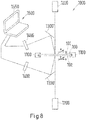
- the verification device preferably has a holder for the security or value document, at least one radiation source, for example a gas discharge lamp, for example a Hg emitter, an LED or the like, at least one imaging optics and at least one radiation receiver, for example a CCD sensor, wherein the Imaging optics and the radiation receiver are arranged to each other such that emitted by the security feature electromagnetic radiation is imaged by the imaging optics on the radiation receiver.
- the apparatus preferably includes an electronic data processing device, such as a personal computer, coupled to the radiation receiver, and a display, such as a personal computer screen.
- the emitted electromagnetic radiation data streams are generated in the radiation receiver, which are read by the electronic data processing in a known manner.
- the data supplied to the electronic data processing device are processed and evaluated therein.
- the image of the security feature obtained from one side of the security or value document can then be displayed on a display, for example the screen of a personal computer, and / or stored in a data memory.
- the emitted radiation from the two document pages can be registered successively or simultaneously. In the case of the naked eye test, this test is carried out in successive steps.
- the security feature can of course also be checked exclusively from one side of the document.
- the test can also be carried out in successive steps by reversing the document after checking the first page of the document and registering the luminescence radiation from the other document side.
- the emitted radiation is recorded simultaneously from both sides of the document.
- the verification device is preferably adapted to receive the document in the holder, which in addition to the radiation sources, each spatially associated with one side of the document, the imaging optics and radiation receivers, which are also spatially associated with each side of the document ,
- the radiation receivers are preferably designed to record the emitted radiation spatially resolved, in particular two-dimensionally resolved.
- the device may preferably have two imaging optics and two radiation receivers, for example CCD sensors. The two images of the security feature recorded by the radiation receivers are supplied to the electronic data processing device and / or stored on the data carrier.
- the images of the security feature originating from the two sides of the document can then be compared, for example, with reference data (data of reference images of the security feature that were created and / or calculated under simulated irradiation conditions). Or the two images are compared with each other, wherein these are in a logical relationship to each other: If the luminescent element is excited, for example by UV radiation and emitted VIS radiation and the absorption element absorbs the UV excitation radiation, is in the examination of the security feature of a first Document side, on which the absorption element is arranged in front of the luminescent element, the image of the absorption element as a shadow in front of the image of the luminescent element recognizable, and is in the examination of the security feature of a second document page, on which the absorption element is arranged behind the luminescent element, also recognizes the image of the absorption element as a shadow, in this case, however, reversed in relation to the luminescence image of the first document page.
- reference data data of reference images of the security feature that were
- the luminescence element can be excited by UV radiation and emits VIS radiation, but the absorption element absorbs the VIS radiation emitted by the luminescent element
- the security feature is checked from the first document side, on which the absorption element is arranged in front of the luminescence element , the image of the absorption element in turn recognizable as a shadow in front of the image of the luminescent element, while in the examination of the security feature of the second document side on which the absorption element is arranged behind the luminescent element, the image of the absorption element in this case is not visible as a shadow, but rather, only the luminescent element by its emitted UV radiation.
- the luminescence on the first document page and / or the luminescence on the second document page of the security or value document are registered in an energy-dispersive manner and the registered energy distribution of the luminescence on the first document page and / or on the second document page with a corresponding one Reference energy distribution compared.
- an even more secure verification of the security or value document is made possible. This prevents, for example, that substitutes for the radiation-absorbing and / or luminescent colorants used in a real document are used to form the security feature. The replacement of the original ones with the substitutes would show up in a changed spectral characteristic of the evaluated spectra.
- both a position in the image of the security feature can be evaluated, which shows only the luminescence of the luminescent element, or a point at which the signal of the luminescent element is shadowed by the absorption element.
- the luminescence can also be registered, and the excitation radiation can be tuned energy-dispersive, so that an excitation spectrum of the luminescent element is obtained.
- This procedure is particularly advantageous when the absorption element absorbs the excitation radiation, so that in this case also the spectral influence of the absorption element can be registered on the luminescence.
- the energy-dispersive registration of the luminescence additionally contains the spectral information of the absorption element, in particular when it absorbs the luminescence radiation.
- a verification device For energy-dispersive registration of the luminescence or energy-dispersive tuning of the excitation radiation, a verification device additionally has at least one energy-dispersive component, for example a diffraction grating or a refraction element.
- the energy-dispersive component In the case of the energy-dispersive registration of the luminescence, the energy-dispersive component is connected in the beam path of the luminescence radiation, while the energy-dispersive component is connected in the case of energy-dispersive tuning of the excitation radiation in the beam path of the excitation radiation.
- the security or value document at an angle ⁇ > 0 ° against a normal to a document page of the security or value document according to method step (b) on the first document side with electromagnetic radiation and / or according to method step (c) on the second document side irradiated with electromagnetic radiation. Since a parallax effect occurs when the two printing planes are spaced apart, different appearances result at different viewing angles, which can also be used to authenticate the security or value document.
- the document can be viewed either with the naked eye, resulting in different viewing angles that certain components of the pattern are shifted from each other, so that a part of the front pattern, if necessary, a part of a pattern behind it hidden.
- a verification device such as by a camera traversing the security feature on a web at different azimuth angles and storing the obtained images of the security feature and processed by an image processing device, the data obtained with previously stored (simulated or comparison) data be compared.
- the opaque printing layer forming the window region, the absorption element and the luminescent element are first applied to individual surfaces of the polymer films, for example printed. Subsequently, the polymer films together with further substrates, for example further polymer films or other film-like materials, such as paper, from which a document body is to be produced, are gathered as layers into a stack, so that the surface provided with the printing layer, the absorption element and the luminescent element / n outside and / or arranged inside is / are. If the stack is welded by introducing heat and pressing pressure into a monolithic laminate, preferably also the absorption element fuses with the surrounding material, so that a nondestructive delamination is no longer possible. If the security feature is on the outside of the laminate after lamination, it can be protected from tampering by subsequent coating with a protective varnish or protective film. The document body produced can then be equipped with further security features, in particular individualizing security features.
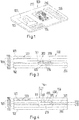
- the security or value document 100 for example an ID card, has a front side 101 and a back side 102 (FIG. Fig. 1 to 5 ; Hereinafter, an ID card will be exemplified for any security or value document).
- the front side has a plurality of personal information fields 103, 104, 105 (such as the facial image, name, date of birth of the card holder and a personal number) identifying the card holder.
- This data is generated on the inside of a surface in the card, ie, for example, under a protective coating 110 on the document body 150 in order to prevent manipulation of this card and also to avoid mechanical damage to the card.
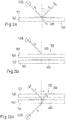
- the ID card 100 has a window area 210 (FIG. Fig. 3, 4 ) or 210 ', 210 "( Fig. 5 ) in an otherwise opaque print layer 200 (FIG. Fig. 3, 4 ) or 200 ', 200 "( Fig. 5 ) on.
- This print layer is printed with a printing ink containing, for example, a white pigment (such as titanium dioxide) formed with a printable binder formed by a geminal disubstituted dihydroxydiphenylcycloalkane-based PC derivative.
- a printing ink containing, for example, a white pigment (such as titanium dioxide) formed with a printable binder formed by a geminal disubstituted dihydroxydiphenylcycloalkane-based PC derivative.
- Such inks are for example in DE 10 2008 012 419 A1 described. insofar is referred to the local revelation.
- This ink has the property of forming a very strong bond with the polymer layer on which the ink is printed and with the other polymer layer which is also in contact with the printed ink in the layer composite.
- a non-delaminatable polymer layer composite can be formed, although the ink has been produced in a blanket printing layer.
- the printing layer can be applied by any printing method, for example by a flexo or screen printing method.
- Both the polymer layers 120, 130 and the upper protective coating 110, which are located above the one with the print layer 200 (FIG. Fig. 3, 4 ) and the polymer layer 140 and the underlying lower protective coating 110 are transparent.
- Two markings are provided in the window area 210, forming the security feature according to the present invention, namely an absorption element 300 (FIG. Fig. 3, 4 ) or 300 ', 300 "( Fig. 5 ) and a luminescent element 400.
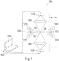
- Fig. 2a is an ID card 100 '(not according to the invention) with a luminescent element 400, but not with an absorption element.
- the luminescent element is formed by a color which fluoresces by excitation with UV radiation, for example in the visible (VIS) spectral range.
- the UV excitation radiation S e radiated by a UV radiation source 1200 impinges on the luminescent element and penetrates partially through the UV color (radiation fraction S t ), because in the present case only part of the UV excitation radiation is absorbed in the UV color layer , The absorbed portion of the irradiated UV excitation radiation leads to an excitation of the luminescence element for luminescence, the then luminescence radiation S l radiates in the visible spectral range. This radiation can be perceived by an observer.
- the luminescence radiation is emitted over the entire spatial area.
- Fig. 2a is shown as representative of other directions of radiation radiated at the angle ⁇ > 0 ° to the map normal radiant component.
- Fig. 2b is an ID card 100 with an absorption element 300, formed by a UV radiation-absorbing UV block varnish, and a luminescent element 400, formed by an excitable by UV radiation to fluorescence color, which emits light at the excitation luminescence in the visible spectral range ,
- the absorption element is arranged on a polymer layer 130, and the luminescent element is arranged on a polymer layer 140.
- Fig. 2bi For example, an arrangement for illuminating the ID card 100 with a UV radiation source 1200 arranged on the card side on which the absorption element 300 is located is shown.
- the excitation radiation S e generated by the radiation source strikes the absorption element and is completely absorbed in it so that it can not reach the luminescence element 400 arranged behind it. Therefore, the luminescent element is not excited by this radiation to luminescence, at least not those parts of the luminescent element, which are covered by the absorption element. If subregions of the luminescent element are not covered by the absorption element, for example because the absorption element is smaller than the luminescence element, these regions can be excited by the excitation radiation for luminescence (not shown here). In this case, the absorption element would be schematically recognizable as a dark area in front of the luminescent areas of the luminescent element.
- Fig. 2bii For example, an arrangement for illuminating the ID card 100 with the UV radiation source 1200, which in this case is arranged on the card side on which the luminescent element 400 is located, is shown.
- the excitation radiation S e generated by the radiation source first strikes the luminescence element and excites it for luminescence, so that the luminescence element emits visible luminescence radiation S l .
- the luminescence radiation is emitted over the entire spatial area.
- Fig. 2bii is only a part of this radiation, which is emitted at an angle ⁇ > 0 ° to the map normal.
- the absorption element 300 Since the absorption element 300 does not absorb the emitted luminescence radiation, it will occur Radiation through the absorption element and can be observed by a viewer. In this arrangement, the luminescence radiation is therefore perceptible by the viewer. The absorption element is therefore not recognizable in front of the luminescent element. This also applies if the absorption element would cover only a portion of the luminescent element. Part of the excitation radiation passes through the luminescent element and strikes the absorption element. The absorption element absorbs the excitation radiation.
- a luminescent element 400 is printed on a surface 141 of the polymer layer 140, for example by means of a screen or flexographic printing process.
- the luminescent element is printed on the polymer layer having the printing layer 200 to form the window region, namely on the same surface on which the printing layer is also located.
- the luminescent element and the print layer may be on separate polymer layers.
- the luminescent element is formed in the form of a flat layer. This layer is placed in the window area in such a way that, for example, it is arranged centrally in the window area and is at a distance from the edges of the window area.
- the luminescent element is to be on a different polymeric layer surface than the printed layer, it is to be located within the window region, ie in a region defined by the projection of the window surface parallel to the normal to the outer sides of the ID card is.
- an absorption element 300 in the form of a pattern 250 (FIG. Fig. 1 ) is printed on the luminescent element 400, for example in the form of a logo or coat of arms.
- the absorption element like the luminescent element 400, is placed in the window region 210, so that this too is visible through the window.
- the absorption element 300 may be such that it does not absorb VIS radiation, but UVA radiation. Therefore, the absorption element is poorly visible to the naked eye.
- the luminescent element 400 can also be used be designed so that it is not visible to the naked eye. For this purpose, it may for example be provided with a luminescent colorant which absorbs electromagnetic radiation in the UVA range, but not VIS radiation. However, the luminescence element can emit VIS radiation when excited for luminescence.
- the absorption element 300 contains a UVA absorber which absorbs the UV radiation used to excite the luminescent element 400 for luminescence
- the logo or emblem can be recognized as a shadow in the luminous surface of the luminescent element, if this is irradiated by irradiation of UVA radiation Luminescence is excited and is considered by the side opposite to the Lumineszenzanregung side of the ID card 100.
- the logo or coat of arms can be seen in this case from both sides of the card, since the luminescent element in the region of this pattern is not excited to luminescence.
- the absorption element 300 contains an absorber which absorbs electromagnetic radiation which is emitted as luminescence radiation by the luminescence element
- the logo or coat of arms can only be recognized from the card side on which the absorption element is located in front of the luminescence element 400. If the absorption element in this case does not absorb the excitation radiation used to excite the luminescent element, the luminescent element is stimulated to luminesce over its entire surface, even if the luminescence element is irradiated by the card side with the excitation radiation on which the absorption element is arranged in front of the luminescence element.
- the luminescence is then visible from the card side, on which the absorption element is located behind the luminescent element, over the entire surface of the luminescent element.
- the absorption element absorbs the emitted luminescence radiation, so that the logo or coat of arms is visible from the card side, on which the absorption element is located in front of the luminescence element.
- a luminescent element 400 in the form of, for example, a logo or coat of arms 250 (FIG. Fig. 1 ) printed on the same surface 141 of the polymer layer 140, on which the print layer 200 is printed to form the window area.
- the luminescent element can be produced by means of a screen or flexographic printing process.
- the absorption element 300 is printed in this embodiment in the document body 150 to the luminescent element 400 spaced on the surface 131 of the located above the polymer layer 140 polymer layer 130.
- the absorption element is located in a first printing plane 310 and the luminescent element 400 in a second printing plane 410.
- the absorbent element is also printed in the window area in this embodiment so that it is visible from both sides of the card 100. It is located just above the luminescent element in the window area 210.
- the absorption element is printed in the same way as the luminescent element in the form of a logo or coat of arms 250, for example, with the same shape, size and orientation and as accurately as possible vertically above the logo or coat of the luminescent element, so both Elements are aligned when viewed parallel to the map normal and overlapping one another.
- the absorption element can in turn be produced by means of a screen or flexographic printing process.
- a third embodiment of the present invention is in the window area 210 ', 210 "of the ID card 100 formed by two print layers 200', 200" on the polymer layers 130 and 140, a first part 300 'of the absorption element on the surface 131 of the polymer layer 130 is arranged. A second part 300 "of the absorption element is arranged on the upper surface 141 of the polymer layer 140.
- Both parts are characterized by dyes or pigments which absorb differently in the VIS region, resulting in differently colored parts of the absorption element
- the spacing of the two parts results in a parallax effect, which produces different color effects of the logo or coat when the card is viewed at different angles ⁇ to the card standard the placement of the absorption element in the window area the same applies as in the other embodiments.
- a luminescent element 400 in the form of a flat layer is printed on the lower surface 142 of the polymer layer 140, for example likewise by means of a screen or flexographic printing process. Regarding the placement of this element, the same applies as previously stated.
- the luminescent element 400 is a biluminescent security feature which can be excited to luminescence by UV radiation and, depending on the wavelength of the excitation, emits either the VIS radiation absorbed by the first part 300 'of the absorption element, or the VIS radiation, the is absorbed by the second part 300 "of the absorption element, either the one part of the logo or coat of arms is selectively visible by shading by the absorption element as a negative in a luminous surface of the luminescent element or the other part of the logo or coat of arms.
- the ID card 100 in this embodiment has two print layers 200 ', 200 "each leaving a blank surface area unprinted defining window areas 210', 210".
- the first print layer 200 ' is arranged on the surface 131 of the polymer layer 130 and the second print layer 200 "on the lower surface 142 of the polymer layer 140.
- an RFID element 500 consisting of an RFID chip and an RFID antenna is arranged on the upper surface 141 of the polymer layer 140.
- the two polymer layers 120, 140 may be writable by means of a laser.
- these polymer layers are formed from PC, which additionally contains carbon particles, so that upon irradiation with the laser results in a blackening.
- a UV-curable ink / ink is preferably used for the production of the absorbent element.
- Such ink / ink may, for example, have the composition shown in Table 1.
- this ink contains a film-forming agent and a radiation-absorbing agent.
- the film-forming agent contains a passive resin, namely, pre-oligomers, polymerizable monomeric compounds, photoinitiators and other additives. If the absorption element should not absorb in the UV spectral range but in another spectral range, another radiation-absorbing compound should be used instead of the UV absorber.
- the selected coating raw materials a low network density is achieved, so that the material of the absorption element has thermoplasticity.
- the coating raw materials are so little reactive that a thermoplastic layer is produced because there is no crosslinking of the film-forming components.
- the photoinitiators used essentially cover the UVA, UVB, UVC and VIS spectral range.
- the component 2-hydroxy-2-methyl-propiophenone absorbs especially in the short-wave UV range, so that also near-surface areas cure safely.
- Hg emitter whose emission lines extend over the abovementioned spectral ranges (UVA, UVB, UVC, VIS).
- Fig. 6 the absorption spectra of a print layer before cure (curve (a)) and after cure (curves (b), (c)) are shown. Curves (b), (c) differ in that no UV absorber is contained in one trap (curve (b)), while in the other case (curve (c)) the UV absorber shown in Table 1 is included ,
- the UV absorber according to Table 1 When using the UV absorber according to Table 1, an additional absorption in the UVA range (in particular 340 to 370 nm) can be seen in the cured composition, which also contains the most intense emission line (365 nm) of the Hg emitter. In this spectral region, the radiation supplied by the illumination lamp is absorbed for curing by the UV absorber and is therefore not available for the polymerization. However, since the spectral regions above and below this absorption region of the UV absorber are available for UV curing, the ink / ink can be UV cured.
- the luminescent element like the absorption element, is produced, for example, by means of a printing process, for example by a screen or flexographic printing process.
- the ink composition may be formed on the basis of a geminal disubstituted dihydroxydiphenylcycloalkane-based PC derivative as in the case of the resist layer forming the window. This will turn on DE 10 2008 012 419 A1 pointed.
- the printing layer for the formation of the window, the absorption element and the luminescent element and optionally further printing elements are printed separately on polymer films or otherwise formed on them, or as in the examples according to the Fig. 3, 4 . 5 partly on the same polymer layer. Then, these films are collected into a stack and in a known manner using pressure under heat to a monolithic Laminated polymer block.
- the lamination is in the case of PC foils typically in a hot / cold laminating press in a first step at 170 to 200 ° C and a pressure of 50 to 600 N / cm 2 and in a second step with cooling to about room temperature and below the same pressure. In the case of PET films, lamination takes place at a higher temperature, for example at 220 ° C.
- the polymer films fuse together.
- the absorption element formed from the thermoplastic polymer formulation is also soft in this joining step and merges with the polymer film surfaces adjacent thereto, so that a very strong compound results in this area, which can no longer be delaminated without destruction.
- the individual ID cards are separated, for example, by punching out of the lamination.
- the adhesive strength of the polymer layers in the laminate is above 7 N / cm.
- the ID card 100 In order to determine the authenticity of the ID card 100, it can either be checked with the naked eye for the presence of the absorption element and of the luminescence element which overlaps it. Alternatively, the card can also be examined in a verification device 1000 ( Fig. 7 . 8th ). This has a holder 1100, which allows to examine the card from both sides.
- the verification device 1000 has four illumination lamps 1200, which illuminate a first card page 101 and a second card page 102 of the card 100. Furthermore, the device also has imaging optics 1300 arranged on both sides of the card as well as radiation receivers 1400, for example CCD sensors. The radiation receivers should be sensitive in the entire spectral range in which an emission signal of the luminescence element is to be expected.
- electromagnetic radiation for example UVA radiation according to the present invention is irradiated on both sides of the security element.
- the radiation emitted by the luminescent element and optionally modified by the absorption element is conducted on both sides via the imaging optics 1300 onto the radiation receivers 1400, wherein the spatial arrangements of the emitted radiation are imaged on the imaging optics on the radiation receiver.
- the radiation received by the radiation receivers is recorded spatially resolved and converted into electrical signals which are fed to a data processing device 1500 with a display 1550.
- the luminescent images taken by the two map pages 101, 102 may be displayed on the display 1550 of the data processing device 1500.
- these two images can be charged with each other, for example, by point (pixel) as subtracted from each other. If necessary, one of the two images must first be mirrored so that a congruence can be generated.
- the verification method (arrangement according to FIG Fig. 8 ) additionally determine the spectral properties of the security feature.
- the card 100 is again clamped in a holder 1100, which allows to examine the card on both sides.
- Electromagnetic radiation is guided, for example, by lasers 1200 in focused beams in the x, y direction over the sides of the cards 101, 102, so that the security feature according to the present invention is scanned in rows or in a grid.
- the luminescence radiation produced in each case is conducted via energy-dispersive elements 1300 ', for example diffraction gratings, and then onto radiation receivers 1400, for example CCD sensors.
- the signals obtained contain both the information about the location of the luminescence by the security feature is scanned only pointwise, as well as the spectral composition of the luminescence.
- the radiation recorded by the radiation receivers is converted into electrical signals and sent to a data processing device 1500 with a display 1550. There the data are synthesized again to luminescence images.
- the luminescence images from the two sides of the card can be compared with one another in the data processing device, wherein additionally the information about the spectral composition of the luminescence radiation can be evaluated.
- Table 1 Composition of a printing ink / ink for the absorbent element Proportion [% by weight] component CAS-No.
Landscapes
- Health & Medical Sciences (AREA)
- General Health & Medical Sciences (AREA)
- Toxicology (AREA)
- Physics & Mathematics (AREA)
- General Physics & Mathematics (AREA)
- Engineering & Computer Science (AREA)
- Manufacturing & Machinery (AREA)
- Electromagnetism (AREA)
- Spectroscopy & Molecular Physics (AREA)
- Computer Vision & Pattern Recognition (AREA)
- Credit Cards Or The Like (AREA)
Claims (12)
- Document de sécurité ou de valeur (100), formé à partir d'un corps de document (150), qui est fabriqué par laminage d'au moins deux strates de polymère (120, 130, 140) reliées entre elles, dans lequel le corps de document (150) comprend une première face de document (101) et une seconde face de document (102) opposée et dans lequel le corps de document (150) présente au moins une zone de fenêtre (210, 210', 210") et dans lequel respectivement au moins un élément d'absorption (300, 300', 300") ainsi que respectivement au moins un élément luminescent (400) chevauchant l'au moins un élément d'absorption (300, 300', 300") se trouvent dans l'au moins une zone de fenêtre (210, 210', 210"), dans lequel au moins l'au moins un élément d'absorption (300, 300', 300") est formé par un matériau thermoplastique, dans lequel- un moyen d'absorption est utilisé pour générer l'au moins un élément d'absorption (300, 300', 300"), qui absorbe le rayonnement électromagnétique irradié pour exciter l'au moins un élément luminescent (400) aux fins de la luminescence et/ou émis par l'au moins un élément luminescent (400),- le document de sécurité ou de valeur (100) est au moins en partie transparent ou translucide dans la zone de fenêtre (210, 210', 210") de sorte que de la lumière peut traverser ladite zone de part en part tandis qu'une zone de document entourant la zone de fenêtre (210, 210', 210") est opaque,- l'au moins un élément d'absorption (300, 300', 300") forme un motif et- l'au moins un élément luminescent (400) est réalisé sous la forme d'un motif ou sous la forme d'une couche luminescente appliquée de manière uniforme,dans lequel l'au moins un élément d'absorption (300, 300', 300") est disposé, observé depuis la première face de document (101) devant l'élément luminescent (400).
- Document de sécurité ou de valeur (100) selon la revendication 1, caractérisé en ce qu'un moyen d'absorption utilisé pour former l'au moins un élément d'absorption (300, 300', 300") est durcissant aux UV.
- Document de sécurité ou de valeur (100) selon l'une quelconque des revendications précédentes, caractérisé en ce que l'au moins un élément d'absorption (300, 300', 300") est absorbant dans le domaine spectral des UV.
- Document de sécurité ou de valeur (100) selon l'une quelconque des revendications précédentes,
caractérisé en ce que l'au moins un élément luminescent (400) peut être excité au moyen d'un rayonnement UV aux fins de la luminescence. - Document de sécurité ou de valeur (100) selon l'une quelconque des revendications précédentes,
caractérisé en ce qu'au moins un élément d'absorption (300, 300', 300") est disposé dans un premier plan d'impression (310) et au moins un élément luminescent (400) est disposé dans un deuxième plan d'impression (410) tenu à distance du premier plan d'impression (310) dans le corps de document (150). - Document de sécurité ou de valeur (100) selon l'une quelconque des revendications précédentes, caractérisé en ce que l'au moins une zone de fenêtre (210, 210', 210") est formée par au moins une couche d'impression opaque évitant l'au moins une zone de fenêtre (210, 210', 210") sur au moins une surface (141) des au moins deux strates de polymère (120, 130, 140).
- Document de sécurité ou de valeur (100) selon l'une quelconque des revendications précédentes, caractérisé en ce qu'au moins une (120) des au moins deux strates de polymère (120, 130, 140) est réalisée pour être décrite au moyen d'un rayon laser.
- Document de sécurité ou de valeur (100) selon l'une quelconque des revendications précédentes, caractérisé en ce que l'au moins un élément d'absorption (300, 300', 300") peut être fabriqué avec un moyen d'absorption, qui contient les constituants suivants :(a) au moins un moyen filmogène sur la base d'un vernis durcissant aux UV, qui donne lieu du fait d'un durcissement aux UV à un matériau thermoplastique, et(b) au moins un moyen d'absorption de rayonnement, par exemple au moins un colorant et/ou au moins un pigment.
- Document de sécurité ou de valeur selon la revendication 8, caractérisé en ce que le moyen filmogène contient des composants suivants :(i) au moins une résine passive ;(ii) au moins un pré-oligomère ;(iii) au moins un composé monomère polymérisable ; et(iv) au moins un photoinitiateur.
- Procédé servant à vérifier l'authenticité d'un document de sécurité ou de valeur (100), comprenant des étapes de procédé suivantes :(a) de fourniture du document de sécurité ou de valeur (100) à vérifier selon la revendication 1 ;(b) d'irradiation du document de sécurité ou de valeur (100) au niveau d'une première face de document (101) avec un rayonnement électromagnétique, qui est adapté pour exciter l'élément luminescent (400), et d'enregistrement avec une résolution locale de la luminescence au niveau de la première face de document (101), dans lequel une première image luminescente modifiée par un élément d'absorption (300, 300', 300") est générée ;(c) d'irradiation du document de sécurité ou de valeur (100) au niveau d'une seconde face de document (102) avec un rayonnement électromagnétique, qui est adapté pour exciter l'élément luminescent (400), et d'enregistrement avec une résolution locale de la luminescence au niveau de la seconde face de document (102), dans lequel une deuxième image luminescente est générée ;(d) de comparaison d'une première image luminescente à la deuxième image luminescente et d'enregistrement d'une différence entre la première image luminescente et la deuxième image luminescente.
- Procédé servant à vérifier l'authenticité d'un document de sécurité ou de valeur (100) selon la revendication 10, caractérisé en ce que la luminescence au niveau de la première face de document (101) et/ou la luminescence au niveau de la seconde face de document (102) du document de sécurité ou de valeur (100) sont enregistrées de manière dispersive en énergie et la répartition d'énergie enregistrée de la luminescence au niveau de la première face de document (101) et/ou au niveau de la seconde face de document (102) sont comparées à une répartition d'énergie de référence correspondante.
- Procédé servant à vérifier l'authenticité d'un document de sécurité ou de valeur (100) selon l'une quelconque des revendications 10 et 11, caractérisé en ce qu'au moins un élément d'absorption (300, 300', 300") est disposé dans un premier plan d'impression (310) dans le corps de document (150) et au moins un élément luminescent (400) est disposé dans un deuxième plan d'impression (410) tenu à distance du premier plan d'impression (310), et que le document de sécurité ou de valeur (100) est irradié d'un rayonnement électromagnétique selon l'étape de procédé (b) au niveau de la première face de document (101) et/ou d'un rayonnement électromagnétique selon l'étape de procédé (c) au niveau de la seconde face de document (102) selon un angle α > 0° par rapport à une normale par rapport à une face de document (101, 102) du document de sécurité ou de valeur (100).
Applications Claiming Priority (2)
| Application Number | Priority Date | Filing Date | Title |
|---|---|---|---|
| DE102015212492.4A DE102015212492A1 (de) | 2015-07-03 | 2015-07-03 | Sicherheits- oder Wertdokument mit einem Lumineszenzmerkmal und Verfahren zum Prüfen der Echtheit des Sicherheits- oder Wertdokuments |
| PCT/EP2016/065530 WO2017005633A1 (fr) | 2015-07-03 | 2016-07-01 | Document de sécurité ou de valeur présentant un élément luminescent et procédé pour vérifier l'authenticité de ce document de sécurité ou de valeur |
Publications (2)
| Publication Number | Publication Date |
|---|---|
| EP3317114A1 EP3317114A1 (fr) | 2018-05-09 |
| EP3317114B1 true EP3317114B1 (fr) | 2019-09-11 |
Family
ID=56363827
Family Applications (1)
| Application Number | Title | Priority Date | Filing Date |
|---|---|---|---|
| EP16735846.4A Active EP3317114B1 (fr) | 2015-07-03 | 2016-07-01 | Document de sécurité ou de valeur avec une caractéristique luminescente et procédé pour la vérification de l'authenticité du document de sécurité ou de valeur |
Country Status (3)
| Country | Link |
|---|---|
| EP (1) | EP3317114B1 (fr) |
| DE (1) | DE102015212492A1 (fr) |
| WO (1) | WO2017005633A1 (fr) |
Cited By (1)
| Publication number | Priority date | Publication date | Assignee | Title |
|---|---|---|---|---|
| WO2025052155A1 (fr) * | 2023-09-06 | 2025-03-13 | Any Biztonsági Nyomda Nyrt. | Document de sécurité et système de vérification du document de sécurité |
Families Citing this family (15)
| Publication number | Priority date | Publication date | Assignee | Title |
|---|---|---|---|---|
| GB2543054B (en) * | 2015-10-05 | 2018-04-04 | De La Rue Int Ltd | A method for manufacturing a security sheet and an insert for incorporation into a security sheet |
| DE102017004785A1 (de) * | 2017-05-18 | 2018-11-22 | Giesecke+Devrient Currency Technology Gmbh | Produktsicherungselement und Verfahren zur Absicherung von Produkten |
| DE102017113372A1 (de) | 2017-06-19 | 2018-12-20 | Rational Aktiengesellschaft | Verfahren zum Reinigen eines Gargerätes und Reinigungsmittel zur Verwendung in dem Reinigungsverfahren |
| DE102017005778A1 (de) * | 2017-06-19 | 2018-12-20 | Giesecke+Devrient Mobile Security Gmbh | Fluoreszierende Personalisierung mittels Laser |
| US10479128B2 (en) * | 2017-10-27 | 2019-11-19 | Assa Abloy Ab | Security feature |
| CA3007268C (fr) * | 2018-06-05 | 2023-12-12 | Canadian Bank Note Company, Limited | Methode de fabrication d'un document de securite comportant un substrat thermoplastique et une image durcie aux uv et document de securite ainsi forme |
| WO2020091241A1 (fr) | 2018-10-31 | 2020-05-07 | 한국기계연구원 | Substrat de coloration structurelle, procédé de fabrication de substrat de coloration structurelle, et système de vérification de sécurité utilisant un substrat de coloration structurelle ainsi fabriqué |
| DE102019000149A1 (de) * | 2019-01-10 | 2020-07-16 | Mühlbauer Gmbh & Co. Kg | Sicherheitseinlage für ein Ausweisdokument mit transparentem Fenster |
| EP3842254A1 (fr) * | 2019-12-24 | 2021-06-30 | Thales Dis France Sa | Élément de sécurité luminescente personnalisable |
| GB2592235B (en) | 2020-02-20 | 2023-02-01 | De La Rue Int Ltd | A security sheet |
| EP3915778B1 (fr) * | 2020-05-27 | 2023-08-16 | Giesecke+Devrient Mobile Security GmbH | Feuille fluorescente coextrudée |
| US11308257B1 (en) | 2020-12-15 | 2022-04-19 | International Business Machines Corporation | Stacked via rivets in chip hotspots |
| DE102021002213A1 (de) * | 2021-04-27 | 2022-10-27 | Giesecke+Devrient Mobile Security Gmbh | Sicherheitsmerkmal für ein Wertdokument, Wertdokument, Verfahren zur Herstellung eines Sicherheitsmerkmals und Verfahren zur Prüfung eines Sicherheitsmerkmals |
| DE102021002672A1 (de) * | 2021-05-21 | 2022-11-24 | Giesecke+Devrient Currency Technology Gmbh | Verfahren und Vorrichtung zum Prüfen von Wertdokumenten und Verfahren und Vorrichtung zum Erzeugen von Prüfparameter für das Prüfverfahren |
| AU2022413830A1 (en) | 2021-12-13 | 2024-09-12 | Authentix, Inc. | Diffractive displays |
Citations (1)
| Publication number | Priority date | Publication date | Assignee | Title |
|---|---|---|---|---|
| WO2014111405A1 (fr) * | 2013-01-21 | 2014-07-24 | Bundesdruckerei Gmbh | Produit de valeur ou de sécurité et procédé de fabrication d'une caractéristique de sécurité sur ou dans le produit de valeur ou de sécurité |
Family Cites Families (24)
| Publication number | Priority date | Publication date | Assignee | Title |
|---|---|---|---|---|
| US3474027A (en) | 1967-06-19 | 1969-10-21 | Phillips Petroleum Co | Plural stages of sulfur removal |
| DE2907004C2 (de) | 1979-02-22 | 1981-06-25 | GAO Gesellschaft für Automation und Organisation mbH, 8000 München | Ausweiskarte und Verfahren zu ihrer Herstellung |
| DE2952322A1 (de) | 1979-12-24 | 1981-07-02 | Agfa-Gevaert Ag, 5090 Leverkusen | Verfahren zur herstellung faelschungssicherer dokumente |
| US5807461A (en) | 1996-05-09 | 1998-09-15 | Fargo Electronics, Inc. | Lamination technique |
| US6264296B1 (en) | 1997-05-06 | 2001-07-24 | Fargo Electronics, Inc. | Ink jet identification card printer with lamination station |
| US6685312B2 (en) | 1997-10-24 | 2004-02-03 | Fargo Electronics, Inc. | Ink jet card printer |
| DE19860093B4 (de) | 1998-12-23 | 2008-10-09 | Giesecke & Devrient Gmbh | Echtheitsmerkmalskombination für Wertdokumente |
| US6932527B2 (en) | 1999-01-25 | 2005-08-23 | Fargo Electronics, Inc. | Card cartridge |
| DE19934436B4 (de) | 1999-07-22 | 2011-06-22 | Honeywell International Inc., N.J. | Verwendung feinstkörniger anorganischer Leuchtstoffe |
| DE60021710T2 (de) | 2000-06-07 | 2006-06-01 | Sicpa Holding S.A. | Durch UV-Strahlung härtbare Zusammensetzung |
| US7037013B2 (en) | 2001-03-05 | 2006-05-02 | Fargo Electronics, Inc. | Ink-receptive card substrate |
| US6979141B2 (en) | 2001-03-05 | 2005-12-27 | Fargo Electronics, Inc. | Identification cards, protective coatings, films, and methods for forming the same |
| DE10349000A1 (de) | 2003-10-17 | 2005-05-19 | Giesecke & Devrient Gmbh | Sicherheitselement mit Farbkippeffekt |
| EP1529653A1 (fr) | 2003-11-07 | 2005-05-11 | Sicpa Holding S.A. | Document de sécurité, méthode de production d'un document de sécurité et l'utilisation d'un document de sécurité |
| US7654581B2 (en) | 2005-05-06 | 2010-02-02 | Canadian Bank Note Company, Limited | Security document with ultraviolet authentication security feature |
| EP1935663A1 (fr) | 2006-12-18 | 2008-06-25 | Setec Oy | Support de données avec fenêtre de visualisation et son procédé de fabrication |
| DE102007035592B4 (de) | 2007-07-30 | 2023-05-04 | Osram Gmbh | Temperaturstabiler Leuchtstoff, Verwendung eines Leuchtstoffs und Verfahren zur Herstellung eines Leuchtstoffs |
| DE102008012419A1 (de) | 2007-10-31 | 2009-05-07 | Bundesdruckerei Gmbh | Polymerschichtverbund für ein Sicherheits- und/oder Wertdokument, Verfahren zu dessen Herstellung sowie Sicherheits- und/oder Wertdokument |
| DE102009040747B3 (de) | 2009-09-08 | 2011-07-21 | Bundesdruckerei GmbH, 10969 | Bilumineszente Melierfasern, eine diese aufweisende Folie, Dokument mit diesen sowie Verfahren zu ihrer Herstellung und ein Verfahren zur Herstellung eines Dokuments mit diesen |
| DE102010015778A1 (de) | 2010-04-21 | 2011-10-27 | Giesecke & Devrient Gmbh | Sicherheitselement mit Durchsichtsbildbereich |
| DE102010026627A1 (de) | 2010-07-09 | 2012-01-12 | Giesecke & Devrient Gmbh | Alkalimetall-und Erdalkalimetall-Niobate und -Tantalate als Sicherheitmerkmalsstoffe |
| WO2012019226A1 (fr) | 2010-08-11 | 2012-02-16 | Securency International Pty Ltd | Dispositif optiquement variable |
| CN103384899B (zh) * | 2011-03-31 | 2015-07-29 | 富士通先端科技株式会社 | 线传感器单元、自动交易装置 |
| GB2526866A (en) | 2014-06-05 | 2015-12-09 | Univ Bristol | Apparatus for and method of inspecting surface topography of a moving object |
-
2015
- 2015-07-03 DE DE102015212492.4A patent/DE102015212492A1/de not_active Withdrawn
-
2016
- 2016-07-01 WO PCT/EP2016/065530 patent/WO2017005633A1/fr not_active Ceased
- 2016-07-01 EP EP16735846.4A patent/EP3317114B1/fr active Active
Patent Citations (1)
| Publication number | Priority date | Publication date | Assignee | Title |
|---|---|---|---|---|
| WO2014111405A1 (fr) * | 2013-01-21 | 2014-07-24 | Bundesdruckerei Gmbh | Produit de valeur ou de sécurité et procédé de fabrication d'une caractéristique de sécurité sur ou dans le produit de valeur ou de sécurité |
Cited By (1)
| Publication number | Priority date | Publication date | Assignee | Title |
|---|---|---|---|---|
| WO2025052155A1 (fr) * | 2023-09-06 | 2025-03-13 | Any Biztonsági Nyomda Nyrt. | Document de sécurité et système de vérification du document de sécurité |
Also Published As
| Publication number | Publication date |
|---|---|
| WO2017005633A1 (fr) | 2017-01-12 |
| EP3317114A1 (fr) | 2018-05-09 |
| DE102015212492A1 (de) | 2017-01-05 |
| DE102015212492A9 (de) | 2017-02-16 |
Similar Documents
| Publication | Publication Date | Title |
|---|---|---|
| EP3317114B1 (fr) | Document de sécurité ou de valeur avec une caractéristique luminescente et procédé pour la vérification de l'authenticité du document de sécurité ou de valeur | |
| EP3411245B1 (fr) | Produit de valeur ou de sécurité, procédé de fabrication d'un produit semi-fini et procédé de vérification | |
| DE102012218615B4 (de) | Sicherheitsmerkmal für ein Wert- und/oder Sicherheitsprodukt mit Farbverlaufsstruktur und das Sicherheitsmerkmal aufweisendes Wert- und/oder Sicherheitsdokument | |
| DE102013200895B4 (de) | Wert- oder Sicherheitsprodukt sowie Verfahren zur Herstellung eines Sicherheitsmerkmals auf oder in dem Wert- oder Sicherheitsprodukt | |
| EP2903835B1 (fr) | Signe de sécurité et produit de valeur et/ou de sécurité pourvu de ce signe de sécurité | |
| DE102008030182B4 (de) | Wert- oder Sicherheitsdokument und Verfahren zum Bilden mindestens eines Sicherheitsmerkmals bei der Herstellung des Wert- oder Sicherheitsdokuments sowie Verfahren und Mittel zur Verifikation | |
| EP3047429B1 (fr) | Produit de valeur ou de sécurité protégé contre des manipulations frauduleuses et procédé pour vérifier l'authenticité de ce produit de valeur ou de sécurité protégé contre des manipulations frauduleuses | |
| EP3046777B1 (fr) | Procédé de production d'un signe de sécurité d'un produit de valeur ou de sécurité | |
| EP4051509B1 (fr) | Vérification d'un document de sécurité sur la base de morphologies de gouttelettes | |
| DE102019007418A1 (de) | Sicherheitselement und Wertdokument mit visuell und maschinell prüfbaren Sicherheitsmerkmalen, die in räumlicher Beziehung zueinander stehen | |
| EP3256329B1 (fr) | Produit de valeur ou de sécurité et procédé de fabrication de celui-ci avec individualisation décentralisée | |
| DE102013218752A1 (de) | Aktivierbares Wert- oder Sicherheitsprodukt, Verfahren zum Aktivieren und Verfahren zum Herstellen des Wert- oder Sicherheitsproduktes | |
| EP2920001B1 (fr) | Jeu de plusieures exemplaires d'un produit de valeur et/ou de sécurité, et procédé de fabrication d'une caractéristique de sécurité | |
| EP4470790A1 (fr) | Combinaison de plaques d'impression et son procédé de fabrication, d'impression de sécurité et son procédé de fabrication, document d'identité, de valeur ou de sécurité doté d'une telle impression de sécurité et procédé de vérification |
Legal Events
| Date | Code | Title | Description |
|---|---|---|---|
| STAA | Information on the status of an ep patent application or granted ep patent |
Free format text: STATUS: THE INTERNATIONAL PUBLICATION HAS BEEN MADE |
|
| PUAI | Public reference made under article 153(3) epc to a published international application that has entered the european phase |
Free format text: ORIGINAL CODE: 0009012 |
|
| STAA | Information on the status of an ep patent application or granted ep patent |
Free format text: STATUS: REQUEST FOR EXAMINATION WAS MADE |
|
| 17P | Request for examination filed |
Effective date: 20180123 |
|
| AK | Designated contracting states |
Kind code of ref document: A1 Designated state(s): AL AT BE BG CH CY CZ DE DK EE ES FI FR GB GR HR HU IE IS IT LI LT LU LV MC MK MT NL NO PL PT RO RS SE SI SK SM TR |
|
| AX | Request for extension of the european patent |
Extension state: BA ME |
|
| DAV | Request for validation of the european patent (deleted) | ||
| DAX | Request for extension of the european patent (deleted) | ||
| STAA | Information on the status of an ep patent application or granted ep patent |
Free format text: STATUS: EXAMINATION IS IN PROGRESS |
|
| 17Q | First examination report despatched |
Effective date: 20181126 |
|
| GRAP | Despatch of communication of intention to grant a patent |
Free format text: ORIGINAL CODE: EPIDOSNIGR1 |
|
| STAA | Information on the status of an ep patent application or granted ep patent |
Free format text: STATUS: GRANT OF PATENT IS INTENDED |
|
| INTG | Intention to grant announced |
Effective date: 20190415 |
|
| GRAS | Grant fee paid |
Free format text: ORIGINAL CODE: EPIDOSNIGR3 |
|
| GRAA | (expected) grant |
Free format text: ORIGINAL CODE: 0009210 |
|
| STAA | Information on the status of an ep patent application or granted ep patent |
Free format text: STATUS: THE PATENT HAS BEEN GRANTED |
|
| AK | Designated contracting states |
Kind code of ref document: B1 Designated state(s): AL AT BE BG CH CY CZ DE DK EE ES FI FR GB GR HR HU IE IS IT LI LT LU LV MC MK MT NL NO PL PT RO RS SE SI SK SM TR |
|
| REG | Reference to a national code |
Ref country code: GB Ref legal event code: FG4D Free format text: NOT ENGLISH |
|
| REG | Reference to a national code |
Ref country code: CH Ref legal event code: EP |
|
| REG | Reference to a national code |
Ref country code: AT Ref legal event code: REF Ref document number: 1177954 Country of ref document: AT Kind code of ref document: T Effective date: 20190915 |
|
| REG | Reference to a national code |
Ref country code: DE Ref legal event code: R096 Ref document number: 502016006567 Country of ref document: DE Ref country code: IE Ref legal event code: FG4D Free format text: LANGUAGE OF EP DOCUMENT: GERMAN |
|
| REG | Reference to a national code |
Ref country code: NL Ref legal event code: MP Effective date: 20190911 |
|
| REG | Reference to a national code |
Ref country code: LT Ref legal event code: MG4D |
|
| PG25 | Lapsed in a contracting state [announced via postgrant information from national office to epo] |
Ref country code: LT Free format text: LAPSE BECAUSE OF FAILURE TO SUBMIT A TRANSLATION OF THE DESCRIPTION OR TO PAY THE FEE WITHIN THE PRESCRIBED TIME-LIMIT Effective date: 20190911 Ref country code: BG Free format text: LAPSE BECAUSE OF FAILURE TO SUBMIT A TRANSLATION OF THE DESCRIPTION OR TO PAY THE FEE WITHIN THE PRESCRIBED TIME-LIMIT Effective date: 20191211 Ref country code: NO Free format text: LAPSE BECAUSE OF FAILURE TO SUBMIT A TRANSLATION OF THE DESCRIPTION OR TO PAY THE FEE WITHIN THE PRESCRIBED TIME-LIMIT Effective date: 20191211 Ref country code: HR Free format text: LAPSE BECAUSE OF FAILURE TO SUBMIT A TRANSLATION OF THE DESCRIPTION OR TO PAY THE FEE WITHIN THE PRESCRIBED TIME-LIMIT Effective date: 20190911 Ref country code: FI Free format text: LAPSE BECAUSE OF FAILURE TO SUBMIT A TRANSLATION OF THE DESCRIPTION OR TO PAY THE FEE WITHIN THE PRESCRIBED TIME-LIMIT Effective date: 20190911 Ref country code: SE Free format text: LAPSE BECAUSE OF FAILURE TO SUBMIT A TRANSLATION OF THE DESCRIPTION OR TO PAY THE FEE WITHIN THE PRESCRIBED TIME-LIMIT Effective date: 20190911 |
|
| PG25 | Lapsed in a contracting state [announced via postgrant information from national office to epo] |
Ref country code: LV Free format text: LAPSE BECAUSE OF FAILURE TO SUBMIT A TRANSLATION OF THE DESCRIPTION OR TO PAY THE FEE WITHIN THE PRESCRIBED TIME-LIMIT Effective date: 20190911 Ref country code: GR Free format text: LAPSE BECAUSE OF FAILURE TO SUBMIT A TRANSLATION OF THE DESCRIPTION OR TO PAY THE FEE WITHIN THE PRESCRIBED TIME-LIMIT Effective date: 20191212 Ref country code: RS Free format text: LAPSE BECAUSE OF FAILURE TO SUBMIT A TRANSLATION OF THE DESCRIPTION OR TO PAY THE FEE WITHIN THE PRESCRIBED TIME-LIMIT Effective date: 20190911 Ref country code: AL Free format text: LAPSE BECAUSE OF FAILURE TO SUBMIT A TRANSLATION OF THE DESCRIPTION OR TO PAY THE FEE WITHIN THE PRESCRIBED TIME-LIMIT Effective date: 20190911 |
|
| PG25 | Lapsed in a contracting state [announced via postgrant information from national office to epo] |
Ref country code: RO Free format text: LAPSE BECAUSE OF FAILURE TO SUBMIT A TRANSLATION OF THE DESCRIPTION OR TO PAY THE FEE WITHIN THE PRESCRIBED TIME-LIMIT Effective date: 20190911 Ref country code: EE Free format text: LAPSE BECAUSE OF FAILURE TO SUBMIT A TRANSLATION OF THE DESCRIPTION OR TO PAY THE FEE WITHIN THE PRESCRIBED TIME-LIMIT Effective date: 20190911 Ref country code: IT Free format text: LAPSE BECAUSE OF FAILURE TO SUBMIT A TRANSLATION OF THE DESCRIPTION OR TO PAY THE FEE WITHIN THE PRESCRIBED TIME-LIMIT Effective date: 20190911 Ref country code: NL Free format text: LAPSE BECAUSE OF FAILURE TO SUBMIT A TRANSLATION OF THE DESCRIPTION OR TO PAY THE FEE WITHIN THE PRESCRIBED TIME-LIMIT Effective date: 20190911 Ref country code: PL Free format text: LAPSE BECAUSE OF FAILURE TO SUBMIT A TRANSLATION OF THE DESCRIPTION OR TO PAY THE FEE WITHIN THE PRESCRIBED TIME-LIMIT Effective date: 20190911 Ref country code: PT Free format text: LAPSE BECAUSE OF FAILURE TO SUBMIT A TRANSLATION OF THE DESCRIPTION OR TO PAY THE FEE WITHIN THE PRESCRIBED TIME-LIMIT Effective date: 20200113 |
|
| PG25 | Lapsed in a contracting state [announced via postgrant information from national office to epo] |
Ref country code: CZ Free format text: LAPSE BECAUSE OF FAILURE TO SUBMIT A TRANSLATION OF THE DESCRIPTION OR TO PAY THE FEE WITHIN THE PRESCRIBED TIME-LIMIT Effective date: 20190911 Ref country code: IS Free format text: LAPSE BECAUSE OF FAILURE TO SUBMIT A TRANSLATION OF THE DESCRIPTION OR TO PAY THE FEE WITHIN THE PRESCRIBED TIME-LIMIT Effective date: 20200224 Ref country code: SK Free format text: LAPSE BECAUSE OF FAILURE TO SUBMIT A TRANSLATION OF THE DESCRIPTION OR TO PAY THE FEE WITHIN THE PRESCRIBED TIME-LIMIT Effective date: 20190911 Ref country code: SM Free format text: LAPSE BECAUSE OF FAILURE TO SUBMIT A TRANSLATION OF THE DESCRIPTION OR TO PAY THE FEE WITHIN THE PRESCRIBED TIME-LIMIT Effective date: 20190911 |
|
| REG | Reference to a national code |
Ref country code: DE Ref legal event code: R097 Ref document number: 502016006567 Country of ref document: DE |
|
| PLBE | No opposition filed within time limit |
Free format text: ORIGINAL CODE: 0009261 |
|
| STAA | Information on the status of an ep patent application or granted ep patent |
Free format text: STATUS: NO OPPOSITION FILED WITHIN TIME LIMIT |
|
| PG2D | Information on lapse in contracting state deleted |
Ref country code: IS |
|
| PG25 | Lapsed in a contracting state [announced via postgrant information from national office to epo] |
Ref country code: DK Free format text: LAPSE BECAUSE OF FAILURE TO SUBMIT A TRANSLATION OF THE DESCRIPTION OR TO PAY THE FEE WITHIN THE PRESCRIBED TIME-LIMIT Effective date: 20190911 Ref country code: IS Free format text: LAPSE BECAUSE OF FAILURE TO SUBMIT A TRANSLATION OF THE DESCRIPTION OR TO PAY THE FEE WITHIN THE PRESCRIBED TIME-LIMIT Effective date: 20200112 |
|
| 26N | No opposition filed |
Effective date: 20200615 |
|
| PG25 | Lapsed in a contracting state [announced via postgrant information from national office to epo] |
Ref country code: SI Free format text: LAPSE BECAUSE OF FAILURE TO SUBMIT A TRANSLATION OF THE DESCRIPTION OR TO PAY THE FEE WITHIN THE PRESCRIBED TIME-LIMIT Effective date: 20190911 |
|
| PG25 | Lapsed in a contracting state [announced via postgrant information from national office to epo] |
Ref country code: ES Free format text: LAPSE BECAUSE OF FAILURE TO SUBMIT A TRANSLATION OF THE DESCRIPTION OR TO PAY THE FEE WITHIN THE PRESCRIBED TIME-LIMIT Effective date: 20190911 |
|
| PG25 | Lapsed in a contracting state [announced via postgrant information from national office to epo] |
Ref country code: MC Free format text: LAPSE BECAUSE OF FAILURE TO SUBMIT A TRANSLATION OF THE DESCRIPTION OR TO PAY THE FEE WITHIN THE PRESCRIBED TIME-LIMIT Effective date: 20190911 |
|
| REG | Reference to a national code |
Ref country code: CH Ref legal event code: PL |
|
| REG | Reference to a national code |
Ref country code: BE Ref legal event code: MM Effective date: 20200731 |
|
| PG25 | Lapsed in a contracting state [announced via postgrant information from national office to epo] |
Ref country code: IE Free format text: LAPSE BECAUSE OF NON-PAYMENT OF DUE FEES Effective date: 20200701 Ref country code: CH Free format text: LAPSE BECAUSE OF NON-PAYMENT OF DUE FEES Effective date: 20200731 Ref country code: LI Free format text: LAPSE BECAUSE OF NON-PAYMENT OF DUE FEES Effective date: 20200731 Ref country code: LU Free format text: LAPSE BECAUSE OF NON-PAYMENT OF DUE FEES Effective date: 20200701 |
|
| PG25 | Lapsed in a contracting state [announced via postgrant information from national office to epo] |
Ref country code: BE Free format text: LAPSE BECAUSE OF NON-PAYMENT OF DUE FEES Effective date: 20200731 |
|
| PG25 | Lapsed in a contracting state [announced via postgrant information from national office to epo] |
Ref country code: TR Free format text: LAPSE BECAUSE OF FAILURE TO SUBMIT A TRANSLATION OF THE DESCRIPTION OR TO PAY THE FEE WITHIN THE PRESCRIBED TIME-LIMIT Effective date: 20190911 Ref country code: MT Free format text: LAPSE BECAUSE OF FAILURE TO SUBMIT A TRANSLATION OF THE DESCRIPTION OR TO PAY THE FEE WITHIN THE PRESCRIBED TIME-LIMIT Effective date: 20190911 Ref country code: CY Free format text: LAPSE BECAUSE OF FAILURE TO SUBMIT A TRANSLATION OF THE DESCRIPTION OR TO PAY THE FEE WITHIN THE PRESCRIBED TIME-LIMIT Effective date: 20190911 |
|
| PG25 | Lapsed in a contracting state [announced via postgrant information from national office to epo] |
Ref country code: MK Free format text: LAPSE BECAUSE OF FAILURE TO SUBMIT A TRANSLATION OF THE DESCRIPTION OR TO PAY THE FEE WITHIN THE PRESCRIBED TIME-LIMIT Effective date: 20190911 |
|
| REG | Reference to a national code |
Ref country code: AT Ref legal event code: MM01 Ref document number: 1177954 Country of ref document: AT Kind code of ref document: T Effective date: 20210701 |
|
| PG25 | Lapsed in a contracting state [announced via postgrant information from national office to epo] |
Ref country code: AT Free format text: LAPSE BECAUSE OF NON-PAYMENT OF DUE FEES Effective date: 20210701 |
|
| P01 | Opt-out of the competence of the unified patent court (upc) registered |
Effective date: 20230526 |
|
| PGFP | Annual fee paid to national office [announced via postgrant information from national office to epo] |
Ref country code: DE Payment date: 20250722 Year of fee payment: 10 |
|
| PGFP | Annual fee paid to national office [announced via postgrant information from national office to epo] |
Ref country code: GB Payment date: 20250717 Year of fee payment: 10 |
|
| PGFP | Annual fee paid to national office [announced via postgrant information from national office to epo] |
Ref country code: FR Payment date: 20250723 Year of fee payment: 10 |