EP3317154B1 - Verfahren zur steuerung eines hydraulischen hybridfahrzeugs - Google Patents
Verfahren zur steuerung eines hydraulischen hybridfahrzeugs Download PDFInfo
- Publication number
- EP3317154B1 EP3317154B1 EP15735907.6A EP15735907A EP3317154B1 EP 3317154 B1 EP3317154 B1 EP 3317154B1 EP 15735907 A EP15735907 A EP 15735907A EP 3317154 B1 EP3317154 B1 EP 3317154B1
- Authority
- EP
- European Patent Office
- Prior art keywords
- hydraulic
- wheels
- pair
- hydraulic machine
- hybrid vehicle
- Prior art date
- Legal status (The legal status is an assumption and is not a legal conclusion. Google has not performed a legal analysis and makes no representation as to the accuracy of the status listed.)
- Active
Links
Images


Classifications
-
- B—PERFORMING OPERATIONS; TRANSPORTING
- B60—VEHICLES IN GENERAL
- B60W—CONJOINT CONTROL OF VEHICLE SUB-UNITS OF DIFFERENT TYPE OR DIFFERENT FUNCTION; CONTROL SYSTEMS SPECIALLY ADAPTED FOR HYBRID VEHICLES; ROAD VEHICLE DRIVE CONTROL SYSTEMS FOR PURPOSES NOT RELATED TO THE CONTROL OF A PARTICULAR SUB-UNIT
- B60W20/00—Control systems specially adapted for hybrid vehicles
- B60W20/10—Controlling the power contribution of each of the prime movers to meet required power demand
-
- B—PERFORMING OPERATIONS; TRANSPORTING
- B60—VEHICLES IN GENERAL
- B60K—ARRANGEMENT OR MOUNTING OF PROPULSION UNITS OR OF TRANSMISSIONS IN VEHICLES; ARRANGEMENT OR MOUNTING OF PLURAL DIVERSE PRIME-MOVERS IN VEHICLES; AUXILIARY DRIVES FOR VEHICLES; INSTRUMENTATION OR DASHBOARDS FOR VEHICLES; ARRANGEMENTS IN CONNECTION WITH COOLING, AIR INTAKE, GAS EXHAUST OR FUEL SUPPLY OF PROPULSION UNITS IN VEHICLES
- B60K17/00—Arrangement or mounting of transmissions in vehicles
- B60K17/04—Arrangement or mounting of transmissions in vehicles characterised by arrangement, location or kind of gearing
- B60K17/16—Arrangement or mounting of transmissions in vehicles characterised by arrangement, location or kind of gearing of differential gearing
-
- B—PERFORMING OPERATIONS; TRANSPORTING
- B60—VEHICLES IN GENERAL
- B60K—ARRANGEMENT OR MOUNTING OF PROPULSION UNITS OR OF TRANSMISSIONS IN VEHICLES; ARRANGEMENT OR MOUNTING OF PLURAL DIVERSE PRIME-MOVERS IN VEHICLES; AUXILIARY DRIVES FOR VEHICLES; INSTRUMENTATION OR DASHBOARDS FOR VEHICLES; ARRANGEMENTS IN CONNECTION WITH COOLING, AIR INTAKE, GAS EXHAUST OR FUEL SUPPLY OF PROPULSION UNITS IN VEHICLES
- B60K6/00—Arrangement or mounting of plural diverse prime-movers for mutual or common propulsion, e.g. hybrid propulsion systems comprising electric motors and internal combustion engines
- B60K6/08—Prime-movers comprising combustion engines and mechanical or fluid energy storing means
- B60K6/12—Prime-movers comprising combustion engines and mechanical or fluid energy storing means by means of a chargeable fluidic accumulator
-
- B—PERFORMING OPERATIONS; TRANSPORTING
- B60—VEHICLES IN GENERAL
- B60K—ARRANGEMENT OR MOUNTING OF PROPULSION UNITS OR OF TRANSMISSIONS IN VEHICLES; ARRANGEMENT OR MOUNTING OF PLURAL DIVERSE PRIME-MOVERS IN VEHICLES; AUXILIARY DRIVES FOR VEHICLES; INSTRUMENTATION OR DASHBOARDS FOR VEHICLES; ARRANGEMENTS IN CONNECTION WITH COOLING, AIR INTAKE, GAS EXHAUST OR FUEL SUPPLY OF PROPULSION UNITS IN VEHICLES
- B60K6/00—Arrangement or mounting of plural diverse prime-movers for mutual or common propulsion, e.g. hybrid propulsion systems comprising electric motors and internal combustion engines
- B60K6/20—Arrangement or mounting of plural diverse prime-movers for mutual or common propulsion, e.g. hybrid propulsion systems comprising electric motors and internal combustion engines the prime-movers consisting of electric motors and internal combustion engines, e.g. HEVs
- B60K6/50—Architecture of the driveline characterised by arrangement or kind of transmission units
- B60K6/52—Driving a plurality of drive axles, e.g. four-wheel drive
-
- B—PERFORMING OPERATIONS; TRANSPORTING
- B60—VEHICLES IN GENERAL
- B60W—CONJOINT CONTROL OF VEHICLE SUB-UNITS OF DIFFERENT TYPE OR DIFFERENT FUNCTION; CONTROL SYSTEMS SPECIALLY ADAPTED FOR HYBRID VEHICLES; ROAD VEHICLE DRIVE CONTROL SYSTEMS FOR PURPOSES NOT RELATED TO THE CONTROL OF A PARTICULAR SUB-UNIT
- B60W10/00—Conjoint control of vehicle sub-units of different type or different function
- B60W10/04—Conjoint control of vehicle sub-units of different type or different function including control of propulsion units
- B60W10/06—Conjoint control of vehicle sub-units of different type or different function including control of propulsion units including control of combustion engines
-
- B—PERFORMING OPERATIONS; TRANSPORTING
- B60—VEHICLES IN GENERAL
- B60W—CONJOINT CONTROL OF VEHICLE SUB-UNITS OF DIFFERENT TYPE OR DIFFERENT FUNCTION; CONTROL SYSTEMS SPECIALLY ADAPTED FOR HYBRID VEHICLES; ROAD VEHICLE DRIVE CONTROL SYSTEMS FOR PURPOSES NOT RELATED TO THE CONTROL OF A PARTICULAR SUB-UNIT
- B60W10/00—Conjoint control of vehicle sub-units of different type or different function
- B60W10/04—Conjoint control of vehicle sub-units of different type or different function including control of propulsion units
- B60W10/08—Conjoint control of vehicle sub-units of different type or different function including control of propulsion units including control of electric propulsion units, e.g. motors or generators
-
- B—PERFORMING OPERATIONS; TRANSPORTING
- B60—VEHICLES IN GENERAL
- B60W—CONJOINT CONTROL OF VEHICLE SUB-UNITS OF DIFFERENT TYPE OR DIFFERENT FUNCTION; CONTROL SYSTEMS SPECIALLY ADAPTED FOR HYBRID VEHICLES; ROAD VEHICLE DRIVE CONTROL SYSTEMS FOR PURPOSES NOT RELATED TO THE CONTROL OF A PARTICULAR SUB-UNIT
- B60W10/00—Conjoint control of vehicle sub-units of different type or different function
- B60W10/18—Conjoint control of vehicle sub-units of different type or different function including control of braking systems
- B60W10/196—Conjoint control of vehicle sub-units of different type or different function including control of braking systems acting within the driveline, e.g. retarders
-
- B—PERFORMING OPERATIONS; TRANSPORTING
- B60—VEHICLES IN GENERAL
- B60W—CONJOINT CONTROL OF VEHICLE SUB-UNITS OF DIFFERENT TYPE OR DIFFERENT FUNCTION; CONTROL SYSTEMS SPECIALLY ADAPTED FOR HYBRID VEHICLES; ROAD VEHICLE DRIVE CONTROL SYSTEMS FOR PURPOSES NOT RELATED TO THE CONTROL OF A PARTICULAR SUB-UNIT
- B60W10/00—Conjoint control of vehicle sub-units of different type or different function
- B60W10/22—Conjoint control of vehicle sub-units of different type or different function including control of suspension systems
-
- B—PERFORMING OPERATIONS; TRANSPORTING
- B60—VEHICLES IN GENERAL
- B60W—CONJOINT CONTROL OF VEHICLE SUB-UNITS OF DIFFERENT TYPE OR DIFFERENT FUNCTION; CONTROL SYSTEMS SPECIALLY ADAPTED FOR HYBRID VEHICLES; ROAD VEHICLE DRIVE CONTROL SYSTEMS FOR PURPOSES NOT RELATED TO THE CONTROL OF A PARTICULAR SUB-UNIT
- B60W20/00—Control systems specially adapted for hybrid vehicles
- B60W20/10—Controlling the power contribution of each of the prime movers to meet required power demand
- B60W20/15—Control strategies specially adapted for achieving a particular effect
-
- B—PERFORMING OPERATIONS; TRANSPORTING
- B60—VEHICLES IN GENERAL
- B60W—CONJOINT CONTROL OF VEHICLE SUB-UNITS OF DIFFERENT TYPE OR DIFFERENT FUNCTION; CONTROL SYSTEMS SPECIALLY ADAPTED FOR HYBRID VEHICLES; ROAD VEHICLE DRIVE CONTROL SYSTEMS FOR PURPOSES NOT RELATED TO THE CONTROL OF A PARTICULAR SUB-UNIT
- B60W30/00—Purposes of road vehicle drive control systems not related to the control of a particular sub-unit, e.g. of systems using conjoint control of vehicle sub-units
- B60W30/14—Adaptive cruise control
- B60W30/143—Speed control
-
- B—PERFORMING OPERATIONS; TRANSPORTING
- B60—VEHICLES IN GENERAL
- B60W—CONJOINT CONTROL OF VEHICLE SUB-UNITS OF DIFFERENT TYPE OR DIFFERENT FUNCTION; CONTROL SYSTEMS SPECIALLY ADAPTED FOR HYBRID VEHICLES; ROAD VEHICLE DRIVE CONTROL SYSTEMS FOR PURPOSES NOT RELATED TO THE CONTROL OF A PARTICULAR SUB-UNIT
- B60W30/00—Purposes of road vehicle drive control systems not related to the control of a particular sub-unit, e.g. of systems using conjoint control of vehicle sub-units
- B60W30/18—Propelling the vehicle
- B60W30/18009—Propelling the vehicle related to particular drive situations
- B60W30/18018—Start-stop drive, e.g. in a traffic jam
-
- B—PERFORMING OPERATIONS; TRANSPORTING
- B60—VEHICLES IN GENERAL
- B60W—CONJOINT CONTROL OF VEHICLE SUB-UNITS OF DIFFERENT TYPE OR DIFFERENT FUNCTION; CONTROL SYSTEMS SPECIALLY ADAPTED FOR HYBRID VEHICLES; ROAD VEHICLE DRIVE CONTROL SYSTEMS FOR PURPOSES NOT RELATED TO THE CONTROL OF A PARTICULAR SUB-UNIT
- B60W30/00—Purposes of road vehicle drive control systems not related to the control of a particular sub-unit, e.g. of systems using conjoint control of vehicle sub-units
- B60W30/18—Propelling the vehicle
- B60W30/18009—Propelling the vehicle related to particular drive situations
- B60W30/18109—Braking
-
- B—PERFORMING OPERATIONS; TRANSPORTING
- B62—LAND VEHICLES FOR TRAVELLING OTHERWISE THAN ON RAILS
- B62D—MOTOR VEHICLES; TRAILERS
- B62D53/00—Tractor-trailer combinations; Road trains
- B62D53/04—Tractor-trailer combinations; Road trains comprising a vehicle carrying an essential part of the other vehicle's load by having supporting means for the front or rear part of the other vehicle
- B62D53/08—Fifth wheel traction couplings
- B62D53/0857—Auxiliary semi-trailer handling or loading equipment, e.g. ramps, rigs, coupling supports
- B62D53/0864—Dollies for fifth wheel coupling
-
- B—PERFORMING OPERATIONS; TRANSPORTING
- B62—LAND VEHICLES FOR TRAVELLING OTHERWISE THAN ON RAILS
- B62D—MOTOR VEHICLES; TRAILERS
- B62D59/00—Trailers with driven ground wheels or the like
- B62D59/04—Trailers with driven ground wheels or the like driven from propulsion unit on trailer
-
- B—PERFORMING OPERATIONS; TRANSPORTING
- B62—LAND VEHICLES FOR TRAVELLING OTHERWISE THAN ON RAILS
- B62D—MOTOR VEHICLES; TRAILERS
- B62D61/00—Motor vehicles or trailers, characterised by the arrangement or number of wheels, not otherwise provided for, e.g. four wheels in diamond pattern
- B62D61/12—Motor vehicles or trailers, characterised by the arrangement or number of wheels, not otherwise provided for, e.g. four wheels in diamond pattern with variable number of ground engaging wheels, e.g. with some wheels arranged higher than others, or with retractable wheels
-
- B—PERFORMING OPERATIONS; TRANSPORTING
- B60—VEHICLES IN GENERAL
- B60W—CONJOINT CONTROL OF VEHICLE SUB-UNITS OF DIFFERENT TYPE OR DIFFERENT FUNCTION; CONTROL SYSTEMS SPECIALLY ADAPTED FOR HYBRID VEHICLES; ROAD VEHICLE DRIVE CONTROL SYSTEMS FOR PURPOSES NOT RELATED TO THE CONTROL OF A PARTICULAR SUB-UNIT
- B60W50/00—Details of control systems for road vehicle drive control not related to the control of a particular sub-unit, e.g. process diagnostic or vehicle driver interfaces
- B60W2050/0001—Details of the control system
- B60W2050/0043—Signal treatments, identification of variables or parameters, parameter estimation or state estimation
- B60W2050/0052—Filtering, filters
- B60W2050/0054—Cut-off filters, retarders, delaying means, dead zones, threshold values or cut-off frequency
-
- B—PERFORMING OPERATIONS; TRANSPORTING
- B60—VEHICLES IN GENERAL
- B60W—CONJOINT CONTROL OF VEHICLE SUB-UNITS OF DIFFERENT TYPE OR DIFFERENT FUNCTION; CONTROL SYSTEMS SPECIALLY ADAPTED FOR HYBRID VEHICLES; ROAD VEHICLE DRIVE CONTROL SYSTEMS FOR PURPOSES NOT RELATED TO THE CONTROL OF A PARTICULAR SUB-UNIT
- B60W2300/00—Indexing codes relating to the type of vehicle
- B60W2300/14—Tractor-trailers, i.e. combinations of a towing vehicle and one or more towed vehicles, e.g. caravans; Road trains
- B60W2300/145—Semi-trailers
-
- B—PERFORMING OPERATIONS; TRANSPORTING
- B60—VEHICLES IN GENERAL
- B60W—CONJOINT CONTROL OF VEHICLE SUB-UNITS OF DIFFERENT TYPE OR DIFFERENT FUNCTION; CONTROL SYSTEMS SPECIALLY ADAPTED FOR HYBRID VEHICLES; ROAD VEHICLE DRIVE CONTROL SYSTEMS FOR PURPOSES NOT RELATED TO THE CONTROL OF A PARTICULAR SUB-UNIT
- B60W2300/00—Indexing codes relating to the type of vehicle
- B60W2300/14—Tractor-trailers, i.e. combinations of a towing vehicle and one or more towed vehicles, e.g. caravans; Road trains
- B60W2300/147—Road trains
-
- B—PERFORMING OPERATIONS; TRANSPORTING
- B60—VEHICLES IN GENERAL
- B60W—CONJOINT CONTROL OF VEHICLE SUB-UNITS OF DIFFERENT TYPE OR DIFFERENT FUNCTION; CONTROL SYSTEMS SPECIALLY ADAPTED FOR HYBRID VEHICLES; ROAD VEHICLE DRIVE CONTROL SYSTEMS FOR PURPOSES NOT RELATED TO THE CONTROL OF A PARTICULAR SUB-UNIT
- B60W2520/00—Input parameters relating to overall vehicle dynamics
- B60W2520/10—Longitudinal speed
- B60W2520/105—Longitudinal acceleration
-
- B—PERFORMING OPERATIONS; TRANSPORTING
- B60—VEHICLES IN GENERAL
- B60W—CONJOINT CONTROL OF VEHICLE SUB-UNITS OF DIFFERENT TYPE OR DIFFERENT FUNCTION; CONTROL SYSTEMS SPECIALLY ADAPTED FOR HYBRID VEHICLES; ROAD VEHICLE DRIVE CONTROL SYSTEMS FOR PURPOSES NOT RELATED TO THE CONTROL OF A PARTICULAR SUB-UNIT
- B60W2530/00—Input parameters relating to vehicle conditions or values, not covered by groups B60W2510/00 or B60W2520/00
- B60W2530/10—Weight
-
- B—PERFORMING OPERATIONS; TRANSPORTING
- B60—VEHICLES IN GENERAL
- B60W—CONJOINT CONTROL OF VEHICLE SUB-UNITS OF DIFFERENT TYPE OR DIFFERENT FUNCTION; CONTROL SYSTEMS SPECIALLY ADAPTED FOR HYBRID VEHICLES; ROAD VEHICLE DRIVE CONTROL SYSTEMS FOR PURPOSES NOT RELATED TO THE CONTROL OF A PARTICULAR SUB-UNIT
- B60W2540/00—Input parameters relating to occupants
- B60W2540/10—Accelerator pedal position
-
- B—PERFORMING OPERATIONS; TRANSPORTING
- B60—VEHICLES IN GENERAL
- B60W—CONJOINT CONTROL OF VEHICLE SUB-UNITS OF DIFFERENT TYPE OR DIFFERENT FUNCTION; CONTROL SYSTEMS SPECIALLY ADAPTED FOR HYBRID VEHICLES; ROAD VEHICLE DRIVE CONTROL SYSTEMS FOR PURPOSES NOT RELATED TO THE CONTROL OF A PARTICULAR SUB-UNIT
- B60W2540/00—Input parameters relating to occupants
- B60W2540/12—Brake pedal position
-
- B—PERFORMING OPERATIONS; TRANSPORTING
- B60—VEHICLES IN GENERAL
- B60W—CONJOINT CONTROL OF VEHICLE SUB-UNITS OF DIFFERENT TYPE OR DIFFERENT FUNCTION; CONTROL SYSTEMS SPECIALLY ADAPTED FOR HYBRID VEHICLES; ROAD VEHICLE DRIVE CONTROL SYSTEMS FOR PURPOSES NOT RELATED TO THE CONTROL OF A PARTICULAR SUB-UNIT
- B60W2552/00—Input parameters relating to infrastructure
- B60W2552/15—Road slope, i.e. the inclination of a road segment in the longitudinal direction
-
- B—PERFORMING OPERATIONS; TRANSPORTING
- B60—VEHICLES IN GENERAL
- B60W—CONJOINT CONTROL OF VEHICLE SUB-UNITS OF DIFFERENT TYPE OR DIFFERENT FUNCTION; CONTROL SYSTEMS SPECIALLY ADAPTED FOR HYBRID VEHICLES; ROAD VEHICLE DRIVE CONTROL SYSTEMS FOR PURPOSES NOT RELATED TO THE CONTROL OF A PARTICULAR SUB-UNIT
- B60W2710/00—Output or target parameters relating to a particular sub-units
- B60W2710/06—Combustion engines, Gas turbines
- B60W2710/0666—Engine torque
-
- B—PERFORMING OPERATIONS; TRANSPORTING
- B60—VEHICLES IN GENERAL
- B60W—CONJOINT CONTROL OF VEHICLE SUB-UNITS OF DIFFERENT TYPE OR DIFFERENT FUNCTION; CONTROL SYSTEMS SPECIALLY ADAPTED FOR HYBRID VEHICLES; ROAD VEHICLE DRIVE CONTROL SYSTEMS FOR PURPOSES NOT RELATED TO THE CONTROL OF A PARTICULAR SUB-UNIT
- B60W2710/00—Output or target parameters relating to a particular sub-units
- B60W2710/09—Other types of propulsion units, e.g. fluid motors, or type not specified
-
- B—PERFORMING OPERATIONS; TRANSPORTING
- B60—VEHICLES IN GENERAL
- B60W—CONJOINT CONTROL OF VEHICLE SUB-UNITS OF DIFFERENT TYPE OR DIFFERENT FUNCTION; CONTROL SYSTEMS SPECIALLY ADAPTED FOR HYBRID VEHICLES; ROAD VEHICLE DRIVE CONTROL SYSTEMS FOR PURPOSES NOT RELATED TO THE CONTROL OF A PARTICULAR SUB-UNIT
- B60W2710/00—Output or target parameters relating to a particular sub-units
- B60W2710/30—Auxiliary equipments
-
- B—PERFORMING OPERATIONS; TRANSPORTING
- B60—VEHICLES IN GENERAL
- B60W—CONJOINT CONTROL OF VEHICLE SUB-UNITS OF DIFFERENT TYPE OR DIFFERENT FUNCTION; CONTROL SYSTEMS SPECIALLY ADAPTED FOR HYBRID VEHICLES; ROAD VEHICLE DRIVE CONTROL SYSTEMS FOR PURPOSES NOT RELATED TO THE CONTROL OF A PARTICULAR SUB-UNIT
- B60W2720/00—Output or target parameters relating to overall vehicle dynamics
- B60W2720/10—Longitudinal speed
- B60W2720/106—Longitudinal acceleration
-
- B—PERFORMING OPERATIONS; TRANSPORTING
- B62—LAND VEHICLES FOR TRAVELLING OTHERWISE THAN ON RAILS
- B62D—MOTOR VEHICLES; TRAILERS
- B62D59/00—Trailers with driven ground wheels or the like
- B62D59/02—Trailers with driven ground wheels or the like driven from external propulsion unit
-
- Y—GENERAL TAGGING OF NEW TECHNOLOGICAL DEVELOPMENTS; GENERAL TAGGING OF CROSS-SECTIONAL TECHNOLOGIES SPANNING OVER SEVERAL SECTIONS OF THE IPC; TECHNICAL SUBJECTS COVERED BY FORMER USPC CROSS-REFERENCE ART COLLECTIONS [XRACs] AND DIGESTS
- Y02—TECHNOLOGIES OR APPLICATIONS FOR MITIGATION OR ADAPTATION AGAINST CLIMATE CHANGE
- Y02T—CLIMATE CHANGE MITIGATION TECHNOLOGIES RELATED TO TRANSPORTATION
- Y02T10/00—Road transport of goods or passengers
- Y02T10/60—Other road transportation technologies with climate change mitigation effect
- Y02T10/62—Hybrid vehicles
Definitions
- the present invention relates to a method for controlling a hydraulic hybrid vehicle.
- the invention also relates to a control unit for controlling a hydraulic hybrid vehicle, a hydraulic hybrid vehicle, and a computer program arranged to perform the method steps as defined by the above defined method.
- the invention is applicable on hydraulic hybrid vehicles, in particularly hydraulic hybrid heavy duty vehicles, such as trucks.
- a plurality of different vehicles are available that are propelled in different ways depending on its specific purpose.
- electric hybrid busses that are propelled electrically as well as by a conventional internal combustion engine.
- the bus is propelled by an electric machine during low vehicle speed, such as e.g. in connection to a bus stop or in a roundabout.
- engine concepts are also applicable for other type of vehicles having a plurality of start and stop during operation thereof, such as e.g. refuse collection vehicles.
- heavy vehicles are also provided with pure electric propulsion without a conventional internal combustion engine.
- WO2010/098881 A2 relates to a hybrid braking system that operates in conjunction with a foundation braking system, whether an air, hydraulic, electric, mechanical or electric braking system. Recovered energy is returned to the axle wheels in a controlled manner while the vehicle is in motion and certain criteria are met so as to compensate for aerodynamic drag and rolling resistance for instance but not at a rate to accelerate or launch a vehicle.
- the object is achieved by a method according to claim 1.
- a method for controlling a hydraulic hybrid vehicle said hydraulic hybrid vehicle comprising a first pair of wheels, a second pair of wheels and a third pair of wheels; an internal combustion engine connected to said first pair of wheels for propelling said hydraulic hybrid vehicle and a hydraulic propulsion system comprising a first hydraulic machine connected to the second pair of wheels and a second hydraulic machine connected to the third pair of wheels
- the method comprises the steps of receiving a signal indicative of a driving condition, comprising vehicle speed, of said hydraulic hybrid vehicle; comparing the vehicle speed of the driving condition of said hydraulic hybrid vehicle with an upper predetermined threshold speed limit and a lower predetermined threshold speed limit; determining if the vehicle speed of the driving condition is higher than the upper predetermined threshold speed limit; and when the vehicle speed is higher than the upper predetermined threshold speed limit; determining, based on the driving condition, control parameters for operating the first hydraulic machine; controlling the control parameters of the first hydraulic machine for operating the first hydraulic machine; determining if the vehicle speed of the driving condition is lower than the
- first pair of wheels and “second pair of wheels” should in the following and throughout the entire description be interpreted as wheels located on each side of the vehicle as seen in the longitudinal direction of the vehicle.
- the front wheels of the vehicle comprises a pair of wheels where each wheel of the pair of wheels is positioned on a respective left and right side of the vehicle as seen in the longitudinal direction thereof.
- the vehicle may be provided with more than one wheel on each side of the vehicle, such as two wheels of each side of the vehicle.
- the first pair of wheels and the second pair of wheels may be connected to a respective first and second wheel axle.
- the first and/or the second wheel axle may, in some cases, be connected to a differential gear for distribution of torque to the respective wheels.
- the wording "vehicle” should be construed as including tractor vehicles (tractor units), i.e. towing vehicles, as well as trailer vehicles (trailer units), i.e. towed vehicles. Also, in the following description, the wording "vehicle” includes the combination of a tractor unit and a trailer unit. Furthermore, the wording "vehicle” can also include a converter dolly arranged between the tractor unit and the trailer unit.
- the "upper predetermined threshold speed limit” is a speed limit where the hydraulic hybrid vehicle is driving relatively fast.
- the upper predetermined threshold speed limit is not intended to relate to a comparison value for start-stop operations but rather a speed limit of e.g. at least 40 km/h. It is thus only when the vehicle speed of the hydraulic hybrid vehicle is higher than the upper predetermined threshold speed limit that the first hydraulic machine is controlled and operated.
- the first hydraulic machine which of course can be two first hydraulic machines positioned on a respective wheel of the second pair of wheels as will be described further below, is thus a high-speed hydraulic machine arranged to be operated when the vehicle speed is above the upper predetermined threshold speed limit.
- the first hydraulic machine has an operating speed range above vehicle stand still. Hence, the first hydraulic machine has a low torque capacity and a high speed capacity and is therefore not suitable for e.g. start-stop operations.
- a driving condition should be construed as a vehicle condition, either a current vehicle condition or an estimated upcoming vehicle condition.
- a driving condition may relate to a requested acceleration from the vehicle operator, an indication of uphill/downhill road inclination, either a current uphill/downhill road inclination or an upcoming estimated uphill/downhill road inclination, etc.
- the information thereof may be received from a suitable vehicle sensor, GPS, etc.
- control parameters should be understood as parameters arranged to control and operate the first hydraulic machine.
- the control parameters may control the first hydraulic machine to be operated as either a hydraulic motor or as a hydraulic pump.
- the control parameters may control how much the first hydraulic machine propels the second pair of wheels when being operated as a motor, or how much hydraulic fluid the first hydraulic machine distributes to other systems when being operated as a hydraulic pump.
- the hydraulic hybrid vehicle is provided with a first hydraulic machine which, together with the internal combustion engine, can be utilized for higher vehicle speeds.
- the first hydraulic machine can be controlled to provide assistance at higher vehicle speed which thus increases the total vehicle speed range for when hydraulic assistance can be provided to the hydraulic hybrid vehicle.
- This may be especially beneficial for vehicles having a relatively high weight, i.e. a high so-called gross weight, where minor deviations in e.g. road inclination affects the propulsion of the vehicle by only using the internal combustion engine. Further examples will be given below in relation to the detailed example embodiments of the present invention.
- the second hydraulic machine is thus arranged to add propulsion during lower vehicle speeds.
- the hydraulic hybrid vehicle can be provided with propulsion boost from hydraulic motors for an increased vehicle speed range.
- the second hydraulic machine can add propulsion torque to the hydraulic hybrid vehicle for a speed range between e.g. 0-40 km/h and the first hydraulic machine can add propulsion torque to the hydraulic hybrid vehicle for a speed range between e.g. 40 90 km/h.
- the ranges are merely exemplary and that the example is made for illustrating that the first hydraulic machine is arranged to operate at a higher speed range in comparison the speed range of which the second hydraulic machine is arranged to operate.
- the second hydraulic machine can add propulsion torque to the vehicle up to.
- control parameters of the second hydraulic machine may be controlled for operating the second machine as a hydraulic pump. i.e. to conduct generative braking from speeds of e.g. 40 km/h to approximately stand-still.
- the method may comprise the step of controlling the control parameters of the first hydraulic machine for operating the first hydraulic machine as a motor by adding propulsion torque from the first hydraulic machine to the second pair of wheels.
- a propulsion boost can be added to the propulsion from the internal combustion engine. Accordingly, the drivability of the hydraulic hybrid vehicle is increased since the first hydraulic machine can supply propulsion to the vehicle if the propulsion from the internal combustion engine is insufficient for e.g. holding a certain desired vehicle speed. Also, vehicle performance is improved in terms of reduced fuel consumption since the addition of propulsion from the first hydraulic machine enables for a reduction of the propulsion from the internal combustion engine, thus reducing fuel consumption. Accordingly, it is possible to maintain total used power at a constant level by reducing the performance of the internal combustion engine and add propulsion from the first hydraulic machine, or to increase performance by keeping the performance from the internal combustion engine and at the same time add propulsion from the first hydraulic machine. As a further advantage, the gradeability, i.e. the steepness of grade that the vehicle is capable of climbing at efficient speed, is improved.
- the driving condition may comprise an indication of an undesired reduction of vehicle speed
- the method comprising the steps of comparing the undesired reduction of vehicle speed with a predetermined speed reduction threshold rate; determining if the undesired reduction of vehicle speed reduces faster than the predetermined speed reduction threshold rate; and when the vehicle speed reduces faster than the predetermined speed reduction threshold rate; controlling the control parameters of the first hydraulic machine for operating the first hydraulic machine as a motor by adding propulsion torque from the first hydraulic machine to the second pair of wheels.
- the wording "undesired reduction of vehicle speed” should be construed such that the speed of the vehicle is reducing without the vehicle operator actively indicating that such a reduction is desired.
- the vehicle speed is reducing even if speed is set by a cruise controller of the vehicle, or if the vehicle speed is reducing when the accelerator pedal is kept in a fixed position. Such a situation can occur when the vehicle is driving at an upwardly sloping hill, or in case of a sudden increased headwind.
- An undesired reduction of vehicle speed can hence be detected by receiving an indication that the vehicle speed is reducing while at the same time the accelerator pedal is kept in approximately the same position as prior to the reduction of vehicle speed, or a signal indicative of a desired set speed from cruise control is given, which set speed can not be kept.
- An advantage is thus that the vehicle speed can be kept at the desired speed level in cases where the propulsion from the internal combustion engine is insufficient. This may be especially beneficial for larger vehicles with heavy loading where minor uphill gradients can cause the vehicle speed to be undesirably reduced. Hereby, the vehicle performance is improved.
- the driving condition may comprise an indication of an inclination of a road gradient of the hydraulic hybrid vehicle, the method comprising the steps of: comparing the inclination of the road gradient with a predetermined inclination threshold limit; determining if the inclination of the road gradient is larger than the predetermined inclination threshold limit; and when the inclination of the road gradient is larger than the predetermined inclination threshold limit; controlling the control parameters of the first hydraulic machine for operating the first hydraulic machine as a motor by adding propulsion torque from the first hydraulic machine to the second pair of wheels.
- an advantage is thus that the hydraulic hybrid vehicle can be provided with a propulsion boost when driving uphill such that a desired vehicle speed can be kept.
- the road gradient can either be the current road gradient for the vehicle or an upcoming estimated road gradient which can be detected by e.g. a GPS or the like.
- An advantage of receiving an indication of an upcoming road gradient for the vehicle is that the first hydraulic machine can be prepared and arranged to supply propulsion torque before the vehicle arrives at the upward slope of the road.
- predetermined inclination threshold limits can be set depending on the specific vehicle. For example, a larger and heavier vehicle can be allowed to add propulsion torque from the first hydraulic machine at a less steep inclination in comparison to a smaller and less heavy vehicle. Also, the predetermined inclination threshold limits can be set by measuring/detecting the loading of the vehicle, where a loaded vehicle can be allowed to add propulsion torque from the first hydraulic machine at a less steep inclination in comparison to an unloaded vehicle.
- the driving condition may comprise an indication of a change in accelerator pedal position, the method comprising the steps of measuring an acceleration of the vehicle in response to the change in accelerator pedal position; comparing the measured acceleration of the vehicle with a predetermined vehicle acceleration threshold limit; determining if the measured acceleration is lower than the predetermined vehicle acceleration threshold limit; and when the measured acceleration is lower than the predetermined vehicle acceleration threshold limit; controlling the control parameters of the first hydraulic machine for operating the first hydraulic machine as a motor by adding propulsion torque from the first hydraulic machine to the second pair of wheels.
- the first hydraulic machine is controlled to add propulsion torque to the second pair of wheels.
- Such situation may occur if the vehicle initiates an overtaking of another vehicle or if the acceptable speed limit increases and there is a desire to rapidly accelerate the vehicle to the new speed limit.
- An advantage is thus that the hydraulic hybrid vehicle will be accelerated to the desired vehicle speed faster in comparison to only accelerate the vehicle by using the internal combustion engine. This will also reduce the fuel consumption since the acceleration period, which is associated with increased fuel consumption, is reduced.
- the hydraulic hybrid vehicle may comprise a liftable wheel axle, the second pair of wheels being connected to the liftable wheel axle, wherein the driving condition comprises an indication of a wheel axle load pressure of the liftable wheel axle, the method comprising the steps of comparing the wheel axle load pressure of the liftable wheel axle with a maximum allowable load pressure threshold limit; determining if the wheel axle load pressure of the liftable wheel axle is lower then the maximum allowable load pressure threshold limit; and when the wheel axle load pressure of the liftable wheel axle is lower then the maximum allowable load pressure threshold limit; controlling the liftable wheel axle to be positioned in a state where the second pair of wheels are in no contact with the ground surface.
- An advantage is that when there is no desire to use the first hydraulic machine and the load condition of the wheel axles are beneficial, the mechanical resistance from the first hydraulic machine is reduced which thus enables for an "on-demand" addition of the first hydraulic machine.
- a total reduction of fuel consumption is provided for the present embodiment of the present invention.
- the hydraulic propulsion system may comprise a hydraulic accumulator in fluid communication with the first hydraulic machine.
- a buffer tank with high pressure hydraulic fluid is provided for the first hydraulic machine such that high pressure hydraulic fluid can be supplied to the first hydraulic machine in a more rapid manner in comparison to receiving hydraulic fluid form e.g. a hydraulic tank of the vehicle or the like.
- the hydraulic accumulator can of course also be arranged in fluid communication with the second hydraulic machine as is described below.
- the method may comprise the step of controlling the control parameters of the first hydraulic machine for operating the first hydraulic machine as a hydraulic pump by supplying hydraulic fluid from the first hydraulic machine to the hydraulic accumulator.
- the first hydraulic machine can be operated as a pump which increases the energy efficiency of the system.
- the first hydraulic machine thus supplies high pressure hydraulic fluid to the hydraulic accumulator for use at a later stage when there is a desire to operate the first hydraulic machine as a hydraulic motor.
- the driving condition may comprise an indication of an inclination of a downhill slope of the vehicle, the method comprising the steps of comparing the inclination of the downhill slope with a predetermined minimum threshold inclination limit; determining if the inclination of the downhill slope is higher than the predetermined minimum threshold inclination limit; and when the inclination of the downhill slope is higher than the predetermined minimum threshold inclination limit; controlling the control parameters of the first hydraulic machine for operating the first hydraulic machine as a pump for supplying hydraulic fluid to the hydraulic accumulator.
- the driving condition may comprise an indication of an amount of hydraulic fluid being present in the hydraulic accumulator; the method comprising the steps of comparing the amount of hydraulic fluid present in the hydraulic accumulator with a predetermined threshold limit; determining if the amount of hydraulic fluid in the hydraulic accumulator is larger than the predetermined threshold limit; and when the amount of hydraulic fluid in the hydraulic accumulator is larger than the predetermined threshold limit; controlling the internal combustion engine to reduce propulsion torque to the first pair of wheels using control parameters of the internal combustion engine; and controlling the control parameters of the first hydraulic machine for operating the first hydraulic machine as a motor by adding propulsion torque from the first hydraulic machine to said second pair of wheels.
- An advantage is that the first hydraulic machine is controlled to operate as a hydraulic motor if there is a sufficient amount of hydraulic fluid in the accumulator to do so. This is also beneficial in a fuel consumption point of view since the propulsion from the internal combustion engine can be reduced if there is a possibility to add propulsion from the first hydraulic machine.
- the method is thus also suitable to use when driving on a relatively flat road surface. It is also possible to allow the hydraulic accumulator to completely run out of hydraulic fluid if an indication from e.g. a GPS or the like determines that there is a downhill slope further ahead where the first hydraulic machine can be operated as a pump that supplies and fills hydraulic fluid to the hydraulic accumulator.
- a control unit for controlling a hydraulic hybrid vehicle is configured to realise the method according to claims 1 to 10.
- a hydraulic hybrid vehicle comprising a control unit for controlling the hydraulic hybrid vehicle according to claim 11.
- the hydraulic hybrid vehicle may comprise a liftable wheel axle, wherein the second pair of wheels is connected to the liftable wheel axle.
- each wheels of the first pair of wheels may comprise an individual first hydraulic machine.
- the packing arrangement of the vehicle is improved since the hydraulic machine does not have to be incorporated into the relatively tight area of the vehicle driveline.
- the first hydraulic machine may be connected to a differential gearing arrangement for distribution of torque from the first hydraulic machine to each of the wheels of the first pair of wheels.
- the hydraulic propulsion system may comprise a transmission arrangement, said transmission arrangement being connected downstream the first hydraulic machine and upstream the first pair of wheels.
- the transmission arrangement can be an automatic transmission arrangement or a manual transmission arrangement.
- the hydraulic propulsion system may comprise a hydraulic accumulator in fluid communication with the first hydraulic machine.
- the hydraulic propulsion system may comprise a hydraulic pump in fluid communication with said hydraulic accumulator.
- the hydraulic pump can preferably be used for charging the hydraulic accumulator.
- the hydraulic pump may be connected to the internal combustion engine of the hydraulic hybrid vehicle.
- the hydraulic pump may be propelled by an electric motor electrically connected to an electric power system of the hydraulic hybrid vehicle.
- a so-called dynamo charging of the hydraulic accumulator is possible, without the need of propelling the vehicle.
- the hydraulic accumulator can be charged with hydraulic fluid without propelling the vehicle.
- the electricity may be provided to the electrically hydraulic pump by use of cables or standard connections in e.g. the trailer unit.
- the hydraulic hybrid vehicle may further comprise a converter dolly positioned between a tractor unit and a trailer unit of the hydraulic hybrid vehicle.
- the second pair of wheels may be connected to the converter dolly.
- the third pair of wheels may be connected to the converter dolly.
- An advantage is that the propulsion possibilities are provided to other parts of the vehicle, which may be beneficial for vehicle combinations comprising e.g. trailers since the hydraulic propulsion can be provided to wheels positioned further rearwards in comparison to the rearmost wheels of the tractor unit. Further, more axle load is hereby available to the driven wheels of the vehicle which is beneficial in cases where the propulsion needs to be distributed to several wheel axles of the vehicle, such as on low friction areas, etc. Positioning the first hydraulic machine in connection to the converter dolly has the further advantage that it will only be used in cases where the converter dolly is used and the vehicle is provided with a relatively heavy loading.
- positioning the hydraulic machines on the converter dolly can also improve the maneuverability during low speeds in case the converter dolly is individually steered, or to improve the stability during reversing of the vehicle, since propulsion is added to wheels located rearwardly of the tractor unit wheels.
- a further advantage is that the electrically controlled hydraulic pump can be positioned on the converter dolly.
- the converter dolly can be propelled without being connected to the tractor unit. This can be especially beneficial in loading/unloading areas for docking the converter dolly to the trailer and/or tractor unit.
- a computer program comprising program code means for performing any of the steps defined above in relation to the first aspect of the present invention when said program is run on a computer.
- a computer readable medium carrying a computer program comprising program code means for performing any of the steps defined above in relation to the first aspect of the present invention when said program is run on a computer.
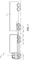
- a hydraulic hybrid vehicle 100 having a tractor unit 1, which is a towing vehicle unit, and a trailer unit 2, which is a towed vehicle unit.
- the tractor unit 1 comprises a cabin 3 for e.g. operation of the hydraulic hybrid vehicle.
- the hydraulic hybrid vehicle 100 depicted in Fig. 1 comprises a converter dolly 300 arranged between the tractor unit 1 and the trailer unit 2.
- the tractor unit of the hydraulic hybrid vehicle 100 comprises a front pair of wheels 110 and two rear pair of wheels 102, 104.
- the front pair of wheels will be denoted as the second pair of wheels
- the foremost pair of wheels of the two rear pair of wheels will be denoted as the first pair of wheels 102
- the rearmost pair of wheels of the two rear pair of wheels will be denoted as the third pair of wheels 104.
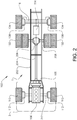
- the hydraulic hybrid vehicle 100 comprises a frame 202 on to which an internal combustion engine 106 is connected.
- the internal combustion engine 106 may be a diesel engine or petrol engine. Other alternative combustion engines are of course also conceivable, such an internal combustion engine propelled by ethanol or gas, etc.
- the internal combustion engine 106 is connected to a drive shaft 204 of the hydraulic hybrid vehicle 100.
- the internal combustion engine 106 may be connected to the drive shaft 204 via a vehicle transmission of suitable kind.
- the internal combustion engine 106 is connected to a first pair of wheels 102, in the illustrated example embodiment depicted in Fig.
- first pair of wheels 102 are driven wheels of the vehicle.
- a first wheel axle 208 of the hydraulic hybrid vehicle 100 connects the first pair of wheels 102 to the differential gearing arrangement 206.
- the internal combustion engine 106 is the primary power source of the hydraulic hybrid vehicle 100.
- the hydraulic hybrid vehicle 100 is primarily propelled by the internal combustion engine 106.
- the hydraulic hybrid vehicle 100 comprises a second pair of wheels 104.
- the second pair of wheels 104 is positioned as the rearmost pair of wheels of the tractor unit 1.
- the second pair of wheels is connected to a second wheel axle.
- the second wheel axle may be arranged as a liftable wheel axle 116.
- the liftable wheel axle 116 may be lifted such that the second pair of wheels is positioned above ground and in no contact with the ground surface.
- the liftable wheel axle 116 may be lifted on a demand from the vehicle operator or at times when the wheel axle loading condition permits such redistribution of wheel axle load to the remaining wheel axles of the vehicle.
- the liftable wheel axle may be lifted by means of controlling air pressure in air bellows (not shown) of the wheel axle suspension.
- air bellows not shown
- each of the wheels of the second pair of wheels 104 are connected to a first hydraulic machine 108.
- the first hydraulic machine 108 is thus arranged to propel the second pair of wheels 104.
- Fig. 2 depicts that each wheel comprises an individual first hydraulic machine 108, it should be readily understood that the second pair of wheels 104 may be connected to a single first hydraulic machine which propels the second pair of wheels 104.
- Such single first hydraulic machine may be connected directly to the liftable wheel axle 116 or connected thereto via e.g. a differential gearing arrangement (not shown).
- the first hydraulic machine 108 is a high-speed hydraulic machine which means that it is only configured to operate at relatively high vehicle speeds. Hence, the first hydraulic machine 108 has an operating speed range which is in the cruising speed range of the hydraulic hybrid vehicle 100. As a non-limiting example, the first hydraulic machine 108 may have an operating speed range between 40 km/h - 90 km/h. As an example, the first hydraulic machine 108 may be a radial hydraulic engine which comprise fewer pistons in comparison to a low-speed hydraulic machine such that the speed can be increased for a specific and constant power level.
- the first hydraulic machine 108 is arranged in fluid communication with a hydraulic accumulator 114 of the hydraulic hybrid vehicle 100.
- the hydraulic accumulator 114 is arranged as a buffer tank for high pressure hydraulic fluid.
- the hydraulic accumulator 114 is also arranged in fluid communication with a hydraulic pump 105.
- the hydraulic pump 105 is a mechanical hydraulic pump connected and controlled by the internal combustion engine 106.
- the hydraulic pump 105 may instead be an electrical hydraulic pump connected to e.g. an electrical power system of the hydraulic hybrid vehicle 100.
- the hydraulic pump 105 hence supplies high pressure hydraulic fluid to the hydraulic accumulator 114 which stores the high pressure hydraulic fluid until providing it to the first hydraulic machine 108.
- the first hydraulic machine 108 may be operated as a hydraulic motor for propelling the second pair of wheels 104, or be operated as a hydraulic pump to supply hydraulic fluid to the hydraulic accumulator 114.
- the hydraulic accumulator 114 may thus receive high pressure hydraulic fluid from the hydraulic pump 105 as well as from the first hydraulic machine 108, in those cases when the first hydraulic machine is controlled to operate as a hydraulic pump. Further details with regards to how the first hydraulic machine is operated will be given below in relation to Fig. 4 .
- the hydraulic hybrid vehicle 100 comprises a third pair of wheels 110.
- the third pair of wheels 110 is positioned as the foremost pair of wheels of the tractor unit 1.
- the third pair of wheels 110 are hence the steerable wheels located under the cabin 3 of the hydraulic hybrid vehicle 100.
- the third pair of wheels 110 is connected to a third wheel axle 212.
- each of the wheels of the third pair of wheels is connected to a second hydraulic machine 112.
- the second hydraulic machine 112 is thus arranged to propel the third pair of wheels 110.
- Fig. 2 depicts that each wheel comprises an individual second hydraulic machine 112, it should be readily understood that the third pair of wheels 110 may be connected to a single second hydraulic machine which propels the third pair of wheels 110.
- Such single second hydraulic machine may be connected directly to the third wheel axle 212 or connected thereto via e.g. a differential gearing arrangement (not shown).
- the second hydraulic machine 112 is a low-speed hydraulic machine which means that it is only configured to operate at relatively low vehicle speeds.
- the second hydraulic machine 112 has an operating speed range which corresponds to start-stop operations of the vehicle and vehicle speeds where the vehicle is in an accelerating phase or driving in city environments, etc.
- the second hydraulic machine 112 may have an operating speed range between 0 km/h - 40 km/h.
- the second hydraulic machine 112 can improve the gradeability on steeper slopes and improve the traction on low friction surfaces, etc.
- the first hydraulic machine 108 is configured to operate at a speed range which is faster than the speed range of the second hydraulic machine 112.
- the first hydraulic machine 108 has a lower torque capacity in comparison to the second hydraulic machine 112 but has on the other hand a higher speed capacity in comparison to the second hydraulic machine 112.
- the second hydraulic machine 112 can also be arranged in fluid communication with the hydraulic accumulator 114 and/or the hydraulic pump 105.
- the second hydraulic machine 112 may be operated as a hydraulic motor for propelling the third pair of wheels 110, or be operated as a pump to supply hydraulic fluid to the hydraulic accumulator 114.
- the hydraulic accumulator 114 may thus receive high pressure hydraulic fluid also from the second hydraulic machine 108, in those cases when the second hydraulic machine 112 is controlled to operate as a pump. Further details with regards to how the second hydraulic machine is operated will be given below in relation to Fig. 4 .
- a converter dolly (or dolly trailer) 300 to which the first 108 and second 112 hydraulic machines can be positioned according to an example embodiment of the present invention.
- the converter dolly 300 is arranged to be positioned between the tractor unit 1 and the trailer unit 2 of the hydraulic hybrid vehicle 100. More particularly, the converter dolly is connected to the tractor unit 1 via a front coupling arrangement 302 and connected to the trailer unit 2 via a so-called fifth wheel 305 of the dolly converter 300.
- the front coupling arrangement 302 does not necessarily have to be connected to the tractor unit 1 but can also be used for connection to another trailer unit 2 in case of a hydraulic hybrid vehicle 100 provided with a plurality of trailer units.
- the dolly converter 300 is provided with a second pair of wheels 304 which is connected to the first hydraulic machine 108, and a third pair of wheels 310 which is connected to the second hydraulic machine 112.
- the internal combustion engine 106 thus propels the first pair of wheels which is positioned on the tractor unit 1 of the hydraulic hybrid vehicle 100.
- the dolly converter 300 depicted in Fig. 3 also comprises a hydraulic accumulator 114 which is arranged in fluid communication with the first 108 and the second 112 hydraulic machines and which functions as described above in relation to Fig. 2 .
- the dolly converter also comprises a hydraulic pump 105 which is arranged in fluid communication with the hydraulic accumulator 114.
- the hydraulic pump 105 may also be in direct fluid communication with the first 108 and the second 112 hydraulic machines.
- the hydraulic pump 105 depicted in Fig. 3 is an electric hydraulic pump which is electrically connected to the electric power system of the hydraulic hybrid vehicle.
- the hydraulic accumulator can be charged by means of so-called dynamo charging during propulsion of the internal combustion engine.
- the first 108 and second 112 hydraulic machines may be arranged on a converter dolly 300 as an alternative to positioning the first 108 and second 112 hydraulic machines on the tractor unit of the hydraulic hybrid vehicle 100.
- Fig. 4 depicts a flow chart of a method for controlling a hydraulic hybrid vehicle according to an example embodiment of the present invention.
- a signal is received S1, which signal is indicative of a driving condition of the hydraulic hybrid vehicle.
- the driving condition comprises at least an indication of the vehicle speed of the hydraulic hybrid vehicle 100.
- the driving condition may also comprise further information relating to vehicle condition or vehicle operating condition.
- the signal may contain information relating to vehicle speed and how it is increased/reduced over a predetermined time period and if the increase/reduction of vehicle speed is a result of a change in accelerator pedal position or not.
- the driving condition may contain information relating to a change in accelerator pedal position over time, which is an indication whether there is a desire to increase/reduce vehicle speed.
- the brake pedal positon or other sensors for determining if the brake is, or is intended to be, applied can also constitute a driving condition.
- the road inclination can also constitute a driving condition.
- Such road inclination can be the present road inclination for the vehicle or an estimated/calculated upcoming road inclination that is located at a certain distance ahead of the vehicle.
- the vehicle speed of the hydraulic hybrid vehicle 100 is thereafter compared S2 to an upper predetermined threshold speed limit. It is thereafter determined S3 if the vehicle speed of the hydraulic hybrid vehicle 100 is higher than the upper predetermined threshold speed limit.
- the vehicle speed of the hydraulic hybrid vehicle 100 is higher than the upper predetermined threshold speed limit.
- the upper predetermined threshold speed limit corresponds to the lower speed limit of the operating speed range for the first hydraulic machine 108.
- control parameters for operating the first hydraulic machine 108 is determined S4 based on the above described driving conditions. Thereafter, the control parameters are controlled S5 for operating the first hydraulic machine.
- the first hydraulic machine 108 is controlled based on the current, or upcoming, vehicle condition. For example, if it is determined that the vehicle is in need of an increased acceleration boost, the control parameters control the first hydraulic machine 108 to be operated as a hydraulic motor to add propulsion to the second pair of wheels 104.
- the internal combustion engine 106, together with the first hydraulic machine 108 will add propulsion to the hydraulic hybrid vehicle 100 for increasing the acceleration thereof.
- control parameters may control the first hydraulic machine to be operated as a hydraulic motor while at the same time control parameters of the internal combustion engine reduces the propulsion from the internal combustion engine.
- control parameters of the internal combustion engine reduces the propulsion from the internal combustion engine.
- the first hydraulic machine can either increase the capacity of the hydraulic hybrid vehicle 100, i.e. provide additional propulsion boost to increase the vehicle speed, or reduce the fuel consumption of the hydraulic hybrid vehicle 100 by reducing propulsion from the internal combustion engine 106, and to keep vehicle speed at a substantially constant cruising speed.
- the driving condition may also contain information relating to a downhill slope of the hydraulic hybrid vehicle.
- the control parameters of the first hydraulic machine 108 may control the first hydraulic machine 108 to be operated as a hydraulic pump which supplies high pressure hydraulic fluid to the hydraulic accumulator 114.
- the high pressure hydraulic fluid provided in the hydraulic accumulator 114 can thereafter be used for propelling the first hydraulic machine 108 when being controlled to be operated as a hydraulic motor.
- the high pressure hydraulic fluid may also be used for propelling the second hydraulic machine 112 when being controlled to be operated as a hydraulic motor.
- the high pressure hydraulic fluid in the hydraulic accumulator 114 can be supplied to the second hydraulic machine 112 during e.g. start-up of the hydraulic hybrid vehicle 100.
- the vehicle speed of the hydraulic hybrid vehicle 100 can also be compared to a lower predetermined threshold speed limit.
- control parameters of the second hydraulic machine 112 is determined based on the driving condition. Thereafter, the control parameters of the second hydraulic machine 112 are controlled for operating the second hydraulic machine 112.
- the control parameters of the second hydraulic machine 112 can be utilized to control the second hydraulic machine 112.
- the control parameters of the second hydraulic machine 112 can control the second hydraulic machine 112 to be operated as a hydraulic pump to further reduce vehicle speed and provide high pressure hydraulic fluid to the hydraulic accumulator 114.
- the control parameters of the second hydraulic machine 112 may also control the second hydraulic machine 112 to be operated as a hydraulic motor by adding propulsion torque from the second hydraulic machine to said third pair of wheels. The latter may be beneficial in start-up situations or when the vehicle is operated at a relatively steep uphill slope and driving in a slow speed.
Landscapes
- Engineering & Computer Science (AREA)
- Transportation (AREA)
- Mechanical Engineering (AREA)
- Chemical & Material Sciences (AREA)
- Combustion & Propulsion (AREA)
- Automation & Control Theory (AREA)
- Hybrid Electric Vehicles (AREA)
- Electric Propulsion And Braking For Vehicles (AREA)
Claims (24)
- Verfahren zur Steuerung eines hydraulischen Hybridfahrzeugs (100), das hydraulische Hybridfahrzeug umfassend:- ein erstes Paar von Rädern (102), ein zweites Paar von Rädern (104) und ein drittes Paar von Rädern (110);- einen Verbrennungsmotor (106), der mit dem ersten Paar von Rädern (102) zum Antreiben des hydraulischen Hybridfahrzeugs verbunden ist; und- ein hydraulisches Antriebssystem, das eine erste hydraulische Maschine (108), die mit dem zweiten Paar von Rädern (104) verbunden ist, und eine zweite hydraulische Maschine (112), die mit dem dritten Paar von Rädern (110) verbunden ist, umfasst, wobei das Verfahren die Schritte umfasst zum:- Empfangen (S1) eines Signals, das eine Fahrbedingung, umfassend Fahrzeuggeschwindigkeit, des hydraulischen Hybridfahrzeugs (100) anzeigt;- Vergleichen (S2) der Fahrzeuggeschwindigkeit der Fahrbedingung des hydraulischen Hybridfahrzeugs (100) mit einer oberen vorgegebenen Schwellengeschwindigkeitsgrenze und einer unteren vorgegebenen Schwellengeschwindigkeitsgrenze;- Bestimmen (S3), ob die Fahrzeuggeschwindigkeit der Fahrbedingung höher als die obere vorgegebene Schwellengeschwindigkeitsgrenze ist; und wann die Fahrzeuggeschwindigkeit höher als die obere vorgegebene Schwellengeschwindigkeitsgrenze ist;- Bestimmen (S4), basierend auf der Fahrbedingung, von Steuerungsparametern zum Betreiben der ersten hydraulischen Maschine (108);- Steuern (S5) der Steuerungsparameter der ersten hydraulischen Maschine (108) zum Betreiben der ersten hydraulischen Maschine;- Bestimmen, ob die Fahrzeuggeschwindigkeit der Fahrbedingung niedriger als die untere vorgegebene Schwellengeschwindigkeitsgrenze ist; und wann die Fahrzeuggeschwindigkeit niedriger als die untere vorgegebene Schwellengeschwindigkeitsgrenze ist;- Bestimmen, basierend auf der Fahrbedingung, von Steuerungsparametern für Betrieb der zweiten hydraulischen Maschine; und- Steuern der Steuerungsparameter der zweiten hydraulischen Maschine zum Betreiben der zweiten hydraulischen Maschine als einen Motor, durch Hinzufügen von Antriebsdrehmoment von der zweiten hydraulischen Maschine zu dem dritten Paar von Rädern (104).
- Verfahren nach Anspruch 1, gekennzeichnet durch Steuern der Steuerungsparameter der ersten hydraulischen Maschine zum Betreiben der ersten hydraulischen Maschine als einen Motor, durch Hinzufügen von Antriebsdrehmoment von der ersten hydraulischen Maschine zu dem zweiten Paar von Rädern (104).
- Verfahren nach Anspruch 1 oder 2, gekennzeichnet durch die Fahrbedingung, umfassend eine Anzeige einer unerwünschten Verringerung von Fahrzeuggeschwindigkeit, das Verfahren umfassend die Schritte zum:- Vergleichen der unerwünschten Verringerung von Fahrzeuggeschwindigkeit mit einer vorgegebenen Geschwindigkeitsverringerungsschwellenrate;- Bestimmen, ob die unerwünschte Verringerung von Fahrzeuggeschwindigkeit sich schneller als die vorgegebene Geschwindigkeitsverringerungsschwellenrate verringert; und wann die Fahrzeuggeschwindigkeit sich schneller als die vorgegebene Geschwindigkeitsverringerungsschwellenrate verringert;- Steuern der Steuerungsparameter der ersten hydraulischen Maschine zum Betreiben der ersten hydraulischen Maschine als einen Motor, durch Hinzufügen von Antriebsdrehmoment von der ersten hydraulischen Maschine zu dem zweiten Paar von Rädern (104).
- Verfahren nach einem der vorstehenden Ansprüche, gekennzeichnet durch die Fahrbedingung, umfassend eine Anzeige einer Neigung eines Straßengradienten des hydraulischen Hybridfahrzeugs, das Verfahren umfassend die Schritte zum:- Vergleichen der Neigung des Straßengradienten mit einer vorgegebenen Neigungsschwellengrenze;- Bestimmen, ob die Neigung des Straßengradienten größer als die vorgegebene Neigungsschwellengrenze ist; und wann die Neigung des Straßengradienten größer als die vorgegebene Neigungsschwellengrenze ist;- Steuern der Steuerungsparameter der ersten hydraulischen Maschine zum Betreiben der ersten hydraulischen Maschine als einen Motor, durch Hinzufügen von Antriebsdrehmoment von der ersten hydraulischen Maschine zu dem zweiten Paar von Rädern (104).
- Verfahren nach einem der vorstehenden Ansprüche, gekennzeichnet durch die Fahrbedingung, umfassend eine Anzeige einer Änderung von Gaspedalposition das Verfahren umfassend die Schritte zum:- Messen einer Beschleunigung des Fahrzeugs in Antwort auf die Änderung von Gaspedalposition;- Vergleichen der gemessenen Beschleunigung des Fahrzeugs mit einer vorgegebenen Fahrzeugbeschleunigungsschwellengrenze;- Bestimmen, ob die gemessene Beschleunigung niedriger als die vorgegebene Fahrzeugbeschleunigungsschwellengrenze ist; und wann die gemessene Beschleunigung niedriger als die vorgegebene Fahrzeugbeschleunigungsschwellengrenze ist;- Steuern der Steuerungsparameter der ersten hydraulischen Maschine zum Betreiben der ersten hydraulischen Maschine als einen Motor, durch Hinzufügen von Antriebsdrehmoment von der ersten hydraulischen Maschine zu dem zweiten Paar von Rädern (104).
- Verfahren nach einem der vorstehenden Ansprüche, gekennzeichnet durch das hydraulische Hybridfahrzeug, das eine Hubradachse (116) umfasst, wobei das zweite Paar von Rädern (104) mit der Hubradachse (116) verbunden ist, wobei die Fahrbedingung eine Anzeige eines Radachsenlastendrucks der Hubradachse umfasst, das Verfahren umfassend die Schritte zum:- Vergleichen des Radachsenlastendrucks der Hubradachse mit einer maximal zulässigen Lastendruckschwellengrenze;- Bestimmen, ob der Radachsenlastendruck der Hubradachse niedriger als die maximal zulässige Lastendruckschwellengrenze ist; und wann der Radachsenlastendruck der Hubradachse niedriger als die maximal zulässige Lastendruckschwellengrenze ist;- Steuern der Hubradachse, in einem Zustand positioniert zu sein, wo das zweite Paar von Rädern in keinem Kontakt mit dem Boden ist.
- Verfahren nach einem der vorstehenden Ansprüche, gekennzeichnet durch das hydraulische Antriebssystem, umfassend einen hydraulischen Akkumulator (114) in Fluidverbindung mit der ersten hydraulischen Maschine.
- Verfahren nach Anspruch 7, gekennzeichnet durch Steuern der Steuerungsparameter der ersten hydraulischen Maschine, um die erste hydraulische Maschine als eine hydraulische Pumpe zu betreiben, indem hydraulisches Fluid von der ersten hydraulischen Maschine dem hydraulischen Akkumulator zugeführt wird.
- Verfahren nach Anspruch 7 oder 8, gekennzeichnet durch die Fahrbedingung, umfassend eine Anzeige einer Neigung einer Abwärtsschräge des Fahrzeugs, das Verfahren umfassend die Schritte zum:- Vergleichen der Neigung der Abwärtsschräge mit einer vorgegebenen minimalen Schwellenneigungsgrenze;- Bestimmen, ob die Neigung der Abwärtsschräge höher als die vorgegebene minimale Schwellenneigungsgrenze ist; und wann die Neigung der Abwärtsschräge höher als die vorgegebene minimale Schwellenneigungsschwelle ist;- Steuern der Steuerungsparameter der ersten hydraulischen Maschine zum Betreiben der ersten hydraulischen Maschine als eine Pumpe zum Zuführen von hydraulischem Fluid zu dem hydraulischen Akkumulator.
- Verfahren nach Anspruch 7, gekennzeichnet durch die Fahrbedingung, umfassend eine Anzeige einer Menge von hydraulischem Fluid, die in dem hydraulischen Akkumulator (114) vorliegt; das Verfahren umfassend die Schritte zum:- Vergleichen der Menge von hydraulischem Fluid, die in dem hydraulischen Akkumulator vorliegt, mit einer vorgegebenen Schwellengrenze;- Bestimmen, ob die Menge von hydraulischem Fluid in dem hydraulischen Akkumulator größer als die vorgegebene Schwellengrenze ist; und wann die Menge von hydraulischem Fluid in dem hydraulischen Akkumulator größer als die vorgegebene Schwellengrenze ist;- Steuern des Verbrennungsmotors (106), um Antriebsdrehmoment zu dem ersten Paar von Rädern (102) unter Verwendung von Steuerungsparametern des Verbrennungsmotors (106) zu verringern; und- Steuern der Steuerungsparameter der ersten hydraulischen Maschine zum Betreiben der ersten hydraulischen Maschine als einen Motor, durch Hinzufügen von Antriebsdrehmoment von der ersten hydraulischen Maschine zu dem zweiten Paar von Rädern (104).
- Steuerungseinheit zum Steuern eines hydraulischen Hybridfahrzeugs (100), das hydraulische Hybridfahrzeug umfassend:- ein erstes Paar von Rädern (102), ein zweites Paar von Rädern (104) und ein drittes Paar von Rädern (110);- einen Verbrennungsmotor (106), der mit dem ersten Paar von Rädern (102) zum Antreiben des hydraulischen Hybridfahrzeugs verbunden ist; und- ein hydraulisches Antriebssystem, umfassend eine erste hydraulische Maschine (108), die mit dem zweiten Paar von Rädern (104) verbunden ist, und eine zweite hydraulische Maschine (112), die mit dem dritten Paar von Rädern (110) verbunden ist, wobei die Steuerungseinheit konfiguriert ist zum:- Empfangen eines Signals, das eine Fahrbedingung, umfassend Fahrzeuggeschwindigkeit, des hydraulischen Hybridfahrzeugs anzeigt;- Vergleichen der Fahrzeuggeschwindigkeit der Fahrbedingung des hydraulischen Hybridfahrzeugs mit einer oberen vorgegebenen Schwellengeschwindigkeitsgrenze und einer unteren vorgegebenen Schwellengeschwindigkeitsgrenze;- Bestimmen, ob die Fahrzeuggeschwindigkeit der Fahrbedingung höher als die obere vorgegebene Schwellengeschwindigkeitsgrenze ist; und wann die Fahrzeuggeschwindigkeit höher als die obere vorgegebene Schwellengeschwindigkeitsgrenze ist;- Bestimmen, basierend auf der Fahrbedingung, von Steuerungsparametern zum Betreiben der ersten hydraulischen Maschine;- Steuern der Steuerungsparameter der ersten hydraulischen Maschine (108) zum Betreiben der ersten hydraulischen Maschine;- Bestimmen, ob die Fahrzeuggeschwindigkeit der Fahrbedingung niedriger als die untere vorgegebene Schwellengeschwindigkeitsgrenze ist; und wann die Fahrzeuggeschwindigkeit niedriger als die untere vorgegebene Schwellengeschwindigkeitsgrenze ist;- Bestimmen, basierend auf der Fahrbedingung, von Steuerungsparametern für Betrieb der zweiten hydraulischen Maschine; und- Steuern der Steuerungsparameter der zweiten hydraulischen Maschine zum Betreiben der zweiten hydraulischen Maschine als einen Motor, durch Hinzufügen von Antriebsdrehmoment von der zweiten hydraulischen Maschine zu dem dritten Paar von Rädern (104).
- Hydraulisches Hybridfahrzeug, wobei das hydraulische Hybridfahrzeug umfasst:- ein erstes Paar von Rädern (102), ein zweites Paar von Rädern (104) und ein drittes Paar von Rädern (110);- einen Verbrennungsmotor (106), der mit dem ersten Paar von Rädern (102) verbunden ist und zum Antreiben des hydraulischen Hybridfahrzeugs angeordnet ist; und- ein hydraulisches Antriebssystem, das eine erste hydraulische Maschine (108), die mit dem zweiten Paar von Rädern (104) verbunden ist, und eine zweite hydraulische Maschine (112), die mit dem dritten Paar von Rädern (110) verbunden ist, umfasst, wobei das hydraulische Hybridfahrzeug eine Steuerungseinheit (200) nach Anspruch 11 umfasst.
- Hydraulisches Hybridfahrzeug nach Anspruch 12, dadurch gekennzeichnet, dass das hydraulische Hybridfahrzeug eine Hubradachse (116) umfasst, wobei das zweite Paar von Rädern mit der Hubradachse (116) verbunden ist.
- Hydraulisches Hybridfahrzeug nach einem der Ansprüche 12-13, dadurch gekennzeichnet, dass jedes der Räder des ersten Paares von Rädern eine individuelle erste hydraulische Maschine umfasst.
- Hydraulisches Hybridfahrzeug nach einem der Ansprüche 12-13, dadurch gekennzeichnet, dass die erste hydraulische Maschine mit einer Differentialgetriebeanordnung zur Verteilung von Drehmoment von der ersten hydraulischen Maschine an jedes der Räder des ersten Paares von Rädern verbunden ist.
- Hydraulisches Hybridfahrzeug nach einem der Ansprüche 12-15, dadurch gekennzeichnet, dass das hydraulische Antriebssystem eine Getriebeanordnung umfasst, wobei die Getriebeanordnung stromabwärts der ersten hydraulischen Maschine und stromaufwärts des ersten Paares von Rädern verbunden ist.
- Hydraulisches Hybridfahrzeug nach einem der Ansprüche 12-16, dadurch gekennzeichnet, dass das hydraulische Antriebssystem einen hydraulischen Akkumulator in Fluidverbindung mit der ersten hydraulischen Maschine umfasst.
- Hydraulisches Hybridfahrzeug nach Anspruch 17, dadurch gekennzeichnet, dass das hydraulische Antriebssystem eine hydraulische Pumpe in Fluidverbindung mit dem hydraulischen Akkumulator umfasst.
- Hydraulisches Hybridfahrzeug nach Anspruch 18, dadurch gekennzeichnet, dass die hydraulische Pumpe mit dem Verbrennungsmotor des hydraulischen Hybridfahrzeugs verbunden ist.
- Hydraulisches Hybridfahrzeug nach Anspruch 18, dadurch gekennzeichnet, dass die hydraulische Pumpe von einem Elektromotor angetrieben wird, der elektrisch mit einem elektrischen Leistungssystem des hydraulischen Hybridfahrzeugs verbunden ist.
- Hydraulisches Hybridfahrzeug nach Ansprüchen 12-20, dadurch gekennzeichnet, dass das hydraulische Hybridfahrzeug weiter einen Kupplungswagen (300) umfasst, der zwischen einer Traktoreinheit und einer Anhängereinheit des hydraulischen Hybridfahrzeugs positioniert ist.
- Hydraulisches Hybridfahrzeug nach Anspruch 21, dadurch gekennzeichnet, dass das zweite (104) und dritte (110) Paar von Rädern mit dem Kupplungswagen (300) verbunden sind.
- Computerprogramm, umfassend Programmcodemittel zum Durchführen der Schritte von Ansprüchen 1-10, wenn das Programm auf einem Computer abläuft.
- Computerlesbares Medium, das ein Computerprogramm trägt, das Programmcodemittel zum Durchführen der Schritte von einem der Ansprüche 1-10 umfasst, wenn das Programm auf einem Computer abläuft.
Applications Claiming Priority (1)
| Application Number | Priority Date | Filing Date | Title |
|---|---|---|---|
| PCT/EP2015/065078 WO2017001017A1 (en) | 2015-07-02 | 2015-07-02 | A method for controlling a hydraulic hybrid vehicle |
Publications (2)
| Publication Number | Publication Date |
|---|---|
| EP3317154A1 EP3317154A1 (de) | 2018-05-09 |
| EP3317154B1 true EP3317154B1 (de) | 2020-03-25 |
Family
ID=53539686
Family Applications (1)
| Application Number | Title | Priority Date | Filing Date |
|---|---|---|---|
| EP15735907.6A Active EP3317154B1 (de) | 2015-07-02 | 2015-07-02 | Verfahren zur steuerung eines hydraulischen hybridfahrzeugs |
Country Status (4)
| Country | Link |
|---|---|
| US (1) | US10654465B2 (de) |
| EP (1) | EP3317154B1 (de) |
| CN (1) | CN107709118B (de) |
| WO (1) | WO2017001017A1 (de) |
Families Citing this family (20)
| Publication number | Priority date | Publication date | Assignee | Title |
|---|---|---|---|---|
| US10870325B2 (en) | 2014-12-16 | 2020-12-22 | Aktv8 LLC | System and method for vehicle stabilization |
| US10675936B2 (en) | 2014-12-16 | 2020-06-09 | Atv8 Llc | System and method for vehicle stabilization |
| CN107249908B (zh) | 2014-12-16 | 2020-02-07 | Aktv8有限公司 | 电子控制的车辆悬架系统和制造方法 |
| US10160278B2 (en) | 2014-12-16 | 2018-12-25 | Aktv8 LLC | System and method for vehicle stabilization |
| ES2926640T3 (es) | 2016-09-06 | 2022-10-27 | Aktv8 LLC | Sistema y procedimientos de gestión de neumáticos |
| US11001261B2 (en) | 2017-01-23 | 2021-05-11 | Volvo Truck Corporation | Method and a system for controlling a vehicle during a downhill start |
| DE102017111254A1 (de) * | 2017-05-23 | 2018-11-29 | Man Truck & Bus Ag | Elektrohydraulische Hybridantriebsvorrichtung für ein Kraftfahrzeug |
| US10449954B2 (en) | 2017-05-30 | 2019-10-22 | Brian P. Layfield | Method and apparatus for an active convertor dolly |
| GB2566494A (en) * | 2017-09-15 | 2019-03-20 | Jaguar Land Rover Ltd | System and method for a trailer towable by a vehicle |
| FR3073957B1 (fr) * | 2017-11-17 | 2019-11-22 | Renault S.A.S | Systeme et procede de datation d'un evenement detecte dans un vehicule automobile |
| CZ308774B6 (cs) * | 2017-12-28 | 2021-05-12 | Mendelova Univerzita V Brně | Vyvážecí traktorová souprava a přívěs nebo návěs |
| DE102018210410B4 (de) * | 2018-06-26 | 2023-06-01 | Bayerische Motoren Werke Aktiengesellschaft | Fahrerassistenzsystem mit einer Nothaltefunktion für ein Fahrzeug, Fahrzeug mit demselben und Verfahren zum Nothalten eines Fahrzeugs |
| CN108803625B (zh) * | 2018-08-09 | 2021-07-23 | 北京智行者科技有限公司 | 一种行驶方法 |
| JP7368206B2 (ja) * | 2019-12-09 | 2023-10-24 | トヨタ自動車株式会社 | 制御装置 |
| JP7395814B2 (ja) * | 2019-12-19 | 2023-12-12 | メルセデス・ベンツ グループ アクチェンゲゼルシャフト | 車両用駆動装置 |
| EP3919303A1 (de) | 2020-06-02 | 2021-12-08 | Scheuerle Fahrzeugfabrik GmbH | Schwerlast-antriebsfahrzeug, insbesondere ein schwerlast-zugfahrzeug oder ein schwerlast-schubfahrzeug |
| DE102020003296A1 (de) | 2020-06-02 | 2021-12-02 | Scheuerle Fahrzeugfabrik Gmbh | Schwerlast-Antriebsfahrzeug, insbesondere ein Schwerlast-Zugfahrzeug oder ein Schwerlast-Schubfahrzeug |
| CN113942517A (zh) * | 2020-07-15 | 2022-01-18 | 厦门雅迅网络股份有限公司 | 一种液压混动汽车动力控制方法、终端设备及存储介质 |
| EP3988434B1 (de) * | 2020-10-22 | 2024-10-16 | Volvo Truck Corporation | Antriebsanordnung für selbstangetriebene rollwagenfahrzeugeinheiten |
| US11530009B2 (en) * | 2021-05-13 | 2022-12-20 | Toyota Motor Engineering & Manufacturing North America, Inc. | Vehicle selectively convertible to a dually configuration |
Family Cites Families (21)
| Publication number | Priority date | Publication date | Assignee | Title |
|---|---|---|---|---|
| DE3542059C1 (de) | 1985-11-28 | 1987-06-04 | Opel Adam Ag | Kraftfahrzeug mit Hauptantriebsachse und zuschaltbarer Antriebsachse |
| US4854409A (en) * | 1987-11-19 | 1989-08-08 | Lear Siegler, Inc. | Lift axle control system |
| US5332052A (en) | 1992-10-19 | 1994-07-26 | Louis Carnevale | Detachable all terrain trailer |
| US5607027A (en) * | 1995-04-28 | 1997-03-04 | Anser, Inc. | Hydraulic drive system for a vehicle |
| JP3861321B2 (ja) * | 1996-05-02 | 2006-12-20 | トヨタ自動車株式会社 | ハイブリッド車 |
| FR2789351B1 (fr) | 1999-02-05 | 2001-04-27 | Poclain Hydraulics Ind | Dispositif de transmission d'un engin mobile ayant au moins deux ponts moteurs |
| JP3712652B2 (ja) | 2001-09-28 | 2005-11-02 | ジヤトコ株式会社 | パラレルハイブリッド車両 |
| JP3991983B2 (ja) | 2003-12-19 | 2007-10-17 | 日産自動車株式会社 | 車両の駆動制御装置 |
| US7111704B2 (en) | 2004-01-30 | 2006-09-26 | Johnson Welded Products, Inc. | Hydrostatic drive apparatus for a road vehicle |
| JP4175415B2 (ja) | 2006-09-19 | 2008-11-05 | トヨタ自動車株式会社 | 車両およびその制御方法 |
| US8118132B2 (en) | 2006-10-18 | 2012-02-21 | The United States Of America As Represented By The Administrator Of The U.S. Environmental Protection Agency | Hydraulic hybrid vehicle method of safe operation |
| DE102007053266A1 (de) | 2007-11-08 | 2009-05-14 | Agco Gmbh | Nutzfahrzeug mit mindestens drei antreibbaren Fahrzeugachsen |
| US7976110B2 (en) | 2009-02-27 | 2011-07-12 | Rini Guy Thomas | Hybrid braking system |
| FR2945243B1 (fr) | 2009-05-11 | 2012-06-01 | Renault Sas | Systeme de commande du couple aux roues d'un vehicule equipe d'au moins un moteur electrique. |
| FR2956462B1 (fr) * | 2010-02-18 | 2012-05-18 | Poclain Hydraulics Ind | Dispositif de transmission hydraulique dont la pompe principale peut etre actionnee en permanence. |
| EP2371645B1 (de) * | 2010-03-25 | 2012-12-05 | Iveco S.p.A. | Verfahren zur Betätigung der Stopp- und Startfunktion in einem sich bewegenden Fahrzeug, insbesondere von Industrie-, Nutz- oder Spezialfahrzeugen |
| DE102010023316A1 (de) | 2010-06-10 | 2011-12-15 | Voith Patent Gmbh | Verfahren zur Einstellung von Schaltpunkten in einem Getriebe oder zur Erhöhung des Drehmoments einer elektrischen Antriebsmaschine |
| US20130240279A1 (en) | 2010-12-10 | 2013-09-19 | International Truck Intellectual Property Company Llc | Hybrid tandem drive axle of a truck vehicle |
| WO2013056723A1 (en) | 2011-10-19 | 2013-04-25 | Volvo Lastvagnar Ab | Vehicle traction control method and system |
| US9108498B2 (en) | 2011-11-15 | 2015-08-18 | Gm Global Technology Operations, Llc | Hydrostatic hydraulic hybrid system |
| JP5966428B2 (ja) * | 2012-02-27 | 2016-08-10 | 日産自動車株式会社 | 車両用駆動制御装置、車両用駆動制御方法 |
-
2015
- 2015-07-02 EP EP15735907.6A patent/EP3317154B1/de active Active
- 2015-07-02 CN CN201580081413.XA patent/CN107709118B/zh not_active Expired - Fee Related
- 2015-07-02 WO PCT/EP2015/065078 patent/WO2017001017A1/en not_active Ceased
- 2015-07-02 US US15/737,332 patent/US10654465B2/en active Active
Non-Patent Citations (1)
| Title |
|---|
| None * |
Also Published As
| Publication number | Publication date |
|---|---|
| CN107709118B (zh) | 2020-11-03 |
| US20180170344A1 (en) | 2018-06-21 |
| US10654465B2 (en) | 2020-05-19 |
| CN107709118A (zh) | 2018-02-16 |
| EP3317154A1 (de) | 2018-05-09 |
| WO2017001017A1 (en) | 2017-01-05 |
Similar Documents
| Publication | Publication Date | Title |
|---|---|---|
| EP3317154B1 (de) | Verfahren zur steuerung eines hydraulischen hybridfahrzeugs | |
| KR101655663B1 (ko) | E-4wd 하이브리드 자동차의 전/후륜 토크 분배 제어 방법 | |
| US10518831B2 (en) | Self-powered actively steerable converter dollies for long combination vehicles | |
| US11845360B2 (en) | Battery charging by towed regenerative braking | |
| CN103043056B (zh) | 控制车轮轴扭矩的方法和用于其的控制系统 | |
| EP4271585B1 (de) | Fahrzeug und verfahren zur steuerung des antriebs eines fahrzeugs | |
| WO2013122101A1 (ja) | 電動駆動式作業車両 | |
| WO2019053025A1 (en) | SYSTEM AND METHOD FOR A TRAILER REMORABLE BY A VEHICLE | |
| JP2025020300A (ja) | ハイブリッド車両における多軸駆動能力の維持 | |
| US20170151954A1 (en) | Control of kinetic energy recovery systems | |
| US12168487B2 (en) | Propulsion arrangement for self-powered dolly vehicle units | |
| JP2016175504A (ja) | ハイブリッド車両及びその制御方法 | |
| US12447970B2 (en) | Downhill target speed acceleration control systems and methods | |
| JP2016175505A (ja) | ハイブリッド車両及びその制御方法 | |
| JP2016175496A (ja) | ハイブリッド車両及びその制御方法 | |
| CN111032398A (zh) | 混合动力机动车辆上的传动模式之间的切换方法 | |
| JP6593045B2 (ja) | ハイブリッド車両及びその制御方法 | |
| CN104670204B (zh) | 利用加速度传感器的车轮驱动系统及具备此系统的车辆 | |
| JP2016175491A (ja) | ハイブリッド車両及びその制御方法 | |
| US11548497B2 (en) | Method and system for propelling a vehicle | |
| JP2016175500A (ja) | ハイブリッド車両及びその制御方法 | |
| JP6593044B2 (ja) | ハイブリッド車両及びその制御方法 | |
| US12441292B2 (en) | Method of controlling operation of a vehicle, computer program, computer-readable medium, control arrangement, and vehicle | |
| US20250058626A1 (en) | Method and control arrangement for transferring a power between electric machines in a vehicle | |
| JP2016175501A (ja) | ハイブリッド車両及びその制御方法 |
Legal Events
| Date | Code | Title | Description |
|---|---|---|---|
| STAA | Information on the status of an ep patent application or granted ep patent |
Free format text: STATUS: THE INTERNATIONAL PUBLICATION HAS BEEN MADE |
|
| PUAI | Public reference made under article 153(3) epc to a published international application that has entered the european phase |
Free format text: ORIGINAL CODE: 0009012 |
|
| STAA | Information on the status of an ep patent application or granted ep patent |
Free format text: STATUS: REQUEST FOR EXAMINATION WAS MADE |
|
| 17P | Request for examination filed |
Effective date: 20180124 |
|
| AK | Designated contracting states |
Kind code of ref document: A1 Designated state(s): AL AT BE BG CH CY CZ DE DK EE ES FI FR GB GR HR HU IE IS IT LI LT LU LV MC MK MT NL NO PL PT RO RS SE SI SK SM TR |
|
| AX | Request for extension of the european patent |
Extension state: BA ME |
|
| DAV | Request for validation of the european patent (deleted) | ||
| DAX | Request for extension of the european patent (deleted) | ||
| RIC1 | Information provided on ipc code assigned before grant |
Ipc: B60W 30/18 20120101ALI20170119BHEP Ipc: B60W 10/08 20060101AFI20170119BHEP Ipc: B60W 50/00 20060101ALI20170119BHEP Ipc: B60W 10/22 20060101ALI20170119BHEP Ipc: B62D 61/12 20060101ALI20170119BHEP Ipc: B60K 6/52 20071001ALI20170119BHEP Ipc: B60W 20/00 20160101ALI20170119BHEP Ipc: B60K 6/12 20060101ALI20170119BHEP |
|
| REG | Reference to a national code |
Ref country code: DE Ref legal event code: R079 Ref document number: 602015049373 Country of ref document: DE Free format text: PREVIOUS MAIN CLASS: B60W0010080000 Ipc: B62D0053080000 |
|
| RIC1 | Information provided on ipc code assigned before grant |
Ipc: B60W 10/22 20060101ALI20191011BHEP Ipc: B60K 6/12 20060101ALI20191011BHEP Ipc: B60W 50/00 20060101ALI20191011BHEP Ipc: B62D 59/02 20060101ALI20191011BHEP Ipc: B60W 20/00 20160101ALI20191011BHEP Ipc: B60W 10/08 20060101ALI20191011BHEP Ipc: B62D 53/08 20060101AFI20191011BHEP Ipc: B60K 6/52 20071001ALI20191011BHEP Ipc: B60W 30/18 20120101ALI20191011BHEP |
|
| GRAP | Despatch of communication of intention to grant a patent |
Free format text: ORIGINAL CODE: EPIDOSNIGR1 |
|
| STAA | Information on the status of an ep patent application or granted ep patent |
Free format text: STATUS: GRANT OF PATENT IS INTENDED |
|
| INTG | Intention to grant announced |
Effective date: 20191220 |
|
| GRAS | Grant fee paid |
Free format text: ORIGINAL CODE: EPIDOSNIGR3 |
|
| GRAA | (expected) grant |
Free format text: ORIGINAL CODE: 0009210 |
|
| STAA | Information on the status of an ep patent application or granted ep patent |
Free format text: STATUS: THE PATENT HAS BEEN GRANTED |
|
| AK | Designated contracting states |
Kind code of ref document: B1 Designated state(s): AL AT BE BG CH CY CZ DE DK EE ES FI FR GB GR HR HU IE IS IT LI LT LU LV MC MK MT NL NO PL PT RO RS SE SI SK SM TR |
|
| REG | Reference to a national code |
Ref country code: GB Ref legal event code: FG4D |
|
| REG | Reference to a national code |
Ref country code: AT Ref legal event code: REF Ref document number: 1248262 Country of ref document: AT Kind code of ref document: T Effective date: 20200415 Ref country code: IE Ref legal event code: FG4D |
|
| REG | Reference to a national code |
Ref country code: DE Ref legal event code: R096 Ref document number: 602015049373 Country of ref document: DE |
|
| REG | Reference to a national code |
Ref country code: SE Ref legal event code: TRGR |
|
| PG25 | Lapsed in a contracting state [announced via postgrant information from national office to epo] |
Ref country code: RS Free format text: LAPSE BECAUSE OF FAILURE TO SUBMIT A TRANSLATION OF THE DESCRIPTION OR TO PAY THE FEE WITHIN THE PRESCRIBED TIME-LIMIT Effective date: 20200325 Ref country code: NO Free format text: LAPSE BECAUSE OF FAILURE TO SUBMIT A TRANSLATION OF THE DESCRIPTION OR TO PAY THE FEE WITHIN THE PRESCRIBED TIME-LIMIT Effective date: 20200625 Ref country code: FI Free format text: LAPSE BECAUSE OF FAILURE TO SUBMIT A TRANSLATION OF THE DESCRIPTION OR TO PAY THE FEE WITHIN THE PRESCRIBED TIME-LIMIT Effective date: 20200325 |
|
| PG25 | Lapsed in a contracting state [announced via postgrant information from national office to epo] |
Ref country code: GR Free format text: LAPSE BECAUSE OF FAILURE TO SUBMIT A TRANSLATION OF THE DESCRIPTION OR TO PAY THE FEE WITHIN THE PRESCRIBED TIME-LIMIT Effective date: 20200626 Ref country code: HR Free format text: LAPSE BECAUSE OF FAILURE TO SUBMIT A TRANSLATION OF THE DESCRIPTION OR TO PAY THE FEE WITHIN THE PRESCRIBED TIME-LIMIT Effective date: 20200325 Ref country code: LV Free format text: LAPSE BECAUSE OF FAILURE TO SUBMIT A TRANSLATION OF THE DESCRIPTION OR TO PAY THE FEE WITHIN THE PRESCRIBED TIME-LIMIT Effective date: 20200325 Ref country code: BG Free format text: LAPSE BECAUSE OF FAILURE TO SUBMIT A TRANSLATION OF THE DESCRIPTION OR TO PAY THE FEE WITHIN THE PRESCRIBED TIME-LIMIT Effective date: 20200625 |
|
| REG | Reference to a national code |
Ref country code: NL Ref legal event code: MP Effective date: 20200325 |
|
| REG | Reference to a national code |
Ref country code: LT Ref legal event code: MG4D |
|
| PG25 | Lapsed in a contracting state [announced via postgrant information from national office to epo] |
Ref country code: NL Free format text: LAPSE BECAUSE OF FAILURE TO SUBMIT A TRANSLATION OF THE DESCRIPTION OR TO PAY THE FEE WITHIN THE PRESCRIBED TIME-LIMIT Effective date: 20200325 |
|
| PG25 | Lapsed in a contracting state [announced via postgrant information from national office to epo] |
Ref country code: PT Free format text: LAPSE BECAUSE OF FAILURE TO SUBMIT A TRANSLATION OF THE DESCRIPTION OR TO PAY THE FEE WITHIN THE PRESCRIBED TIME-LIMIT Effective date: 20200818 Ref country code: EE Free format text: LAPSE BECAUSE OF FAILURE TO SUBMIT A TRANSLATION OF THE DESCRIPTION OR TO PAY THE FEE WITHIN THE PRESCRIBED TIME-LIMIT Effective date: 20200325 Ref country code: SM Free format text: LAPSE BECAUSE OF FAILURE TO SUBMIT A TRANSLATION OF THE DESCRIPTION OR TO PAY THE FEE WITHIN THE PRESCRIBED TIME-LIMIT Effective date: 20200325 Ref country code: LT Free format text: LAPSE BECAUSE OF FAILURE TO SUBMIT A TRANSLATION OF THE DESCRIPTION OR TO PAY THE FEE WITHIN THE PRESCRIBED TIME-LIMIT Effective date: 20200325 Ref country code: CZ Free format text: LAPSE BECAUSE OF FAILURE TO SUBMIT A TRANSLATION OF THE DESCRIPTION OR TO PAY THE FEE WITHIN THE PRESCRIBED TIME-LIMIT Effective date: 20200325 Ref country code: IS Free format text: LAPSE BECAUSE OF FAILURE TO SUBMIT A TRANSLATION OF THE DESCRIPTION OR TO PAY THE FEE WITHIN THE PRESCRIBED TIME-LIMIT Effective date: 20200725 Ref country code: RO Free format text: LAPSE BECAUSE OF FAILURE TO SUBMIT A TRANSLATION OF THE DESCRIPTION OR TO PAY THE FEE WITHIN THE PRESCRIBED TIME-LIMIT Effective date: 20200325 Ref country code: SK Free format text: LAPSE BECAUSE OF FAILURE TO SUBMIT A TRANSLATION OF THE DESCRIPTION OR TO PAY THE FEE WITHIN THE PRESCRIBED TIME-LIMIT Effective date: 20200325 |
|
| REG | Reference to a national code |
Ref country code: AT Ref legal event code: MK05 Ref document number: 1248262 Country of ref document: AT Kind code of ref document: T Effective date: 20200325 |
|
| REG | Reference to a national code |
Ref country code: DE Ref legal event code: R097 Ref document number: 602015049373 Country of ref document: DE |
|
| PG25 | Lapsed in a contracting state [announced via postgrant information from national office to epo] |
Ref country code: IT Free format text: LAPSE BECAUSE OF FAILURE TO SUBMIT A TRANSLATION OF THE DESCRIPTION OR TO PAY THE FEE WITHIN THE PRESCRIBED TIME-LIMIT Effective date: 20200325 Ref country code: ES Free format text: LAPSE BECAUSE OF FAILURE TO SUBMIT A TRANSLATION OF THE DESCRIPTION OR TO PAY THE FEE WITHIN THE PRESCRIBED TIME-LIMIT Effective date: 20200325 Ref country code: AT Free format text: LAPSE BECAUSE OF FAILURE TO SUBMIT A TRANSLATION OF THE DESCRIPTION OR TO PAY THE FEE WITHIN THE PRESCRIBED TIME-LIMIT Effective date: 20200325 Ref country code: DK Free format text: LAPSE BECAUSE OF FAILURE TO SUBMIT A TRANSLATION OF THE DESCRIPTION OR TO PAY THE FEE WITHIN THE PRESCRIBED TIME-LIMIT Effective date: 20200325 |
|
| PLBE | No opposition filed within time limit |
Free format text: ORIGINAL CODE: 0009261 |
|
| STAA | Information on the status of an ep patent application or granted ep patent |
Free format text: STATUS: NO OPPOSITION FILED WITHIN TIME LIMIT |
|
| PG25 | Lapsed in a contracting state [announced via postgrant information from national office to epo] |
Ref country code: MC Free format text: LAPSE BECAUSE OF FAILURE TO SUBMIT A TRANSLATION OF THE DESCRIPTION OR TO PAY THE FEE WITHIN THE PRESCRIBED TIME-LIMIT Effective date: 20200325 Ref country code: PL Free format text: LAPSE BECAUSE OF FAILURE TO SUBMIT A TRANSLATION OF THE DESCRIPTION OR TO PAY THE FEE WITHIN THE PRESCRIBED TIME-LIMIT Effective date: 20200325 |
|
| REG | Reference to a national code |
Ref country code: CH Ref legal event code: PL |
|
| 26N | No opposition filed |
Effective date: 20210112 |
|
| GBPC | Gb: european patent ceased through non-payment of renewal fee |
Effective date: 20200702 |
|
| REG | Reference to a national code |
Ref country code: BE Ref legal event code: MM Effective date: 20200731 |
|
| PG25 | Lapsed in a contracting state [announced via postgrant information from national office to epo] |
Ref country code: LU Free format text: LAPSE BECAUSE OF NON-PAYMENT OF DUE FEES Effective date: 20200702 Ref country code: LI Free format text: LAPSE BECAUSE OF NON-PAYMENT OF DUE FEES Effective date: 20200731 Ref country code: CH Free format text: LAPSE BECAUSE OF NON-PAYMENT OF DUE FEES Effective date: 20200731 Ref country code: GB Free format text: LAPSE BECAUSE OF NON-PAYMENT OF DUE FEES Effective date: 20200702 Ref country code: IE Free format text: LAPSE BECAUSE OF NON-PAYMENT OF DUE FEES Effective date: 20200702 |
|
| PG25 | Lapsed in a contracting state [announced via postgrant information from national office to epo] |
Ref country code: BE Free format text: LAPSE BECAUSE OF NON-PAYMENT OF DUE FEES Effective date: 20200731 Ref country code: SI Free format text: LAPSE BECAUSE OF FAILURE TO SUBMIT A TRANSLATION OF THE DESCRIPTION OR TO PAY THE FEE WITHIN THE PRESCRIBED TIME-LIMIT Effective date: 20200325 |
|
| PG25 | Lapsed in a contracting state [announced via postgrant information from national office to epo] |
Ref country code: TR Free format text: LAPSE BECAUSE OF FAILURE TO SUBMIT A TRANSLATION OF THE DESCRIPTION OR TO PAY THE FEE WITHIN THE PRESCRIBED TIME-LIMIT Effective date: 20200325 Ref country code: MT Free format text: LAPSE BECAUSE OF FAILURE TO SUBMIT A TRANSLATION OF THE DESCRIPTION OR TO PAY THE FEE WITHIN THE PRESCRIBED TIME-LIMIT Effective date: 20200325 Ref country code: CY Free format text: LAPSE BECAUSE OF FAILURE TO SUBMIT A TRANSLATION OF THE DESCRIPTION OR TO PAY THE FEE WITHIN THE PRESCRIBED TIME-LIMIT Effective date: 20200325 |
|
| PG25 | Lapsed in a contracting state [announced via postgrant information from national office to epo] |
Ref country code: MK Free format text: LAPSE BECAUSE OF FAILURE TO SUBMIT A TRANSLATION OF THE DESCRIPTION OR TO PAY THE FEE WITHIN THE PRESCRIBED TIME-LIMIT Effective date: 20200325 Ref country code: AL Free format text: LAPSE BECAUSE OF FAILURE TO SUBMIT A TRANSLATION OF THE DESCRIPTION OR TO PAY THE FEE WITHIN THE PRESCRIBED TIME-LIMIT Effective date: 20200325 |
|
| PGFP | Annual fee paid to national office [announced via postgrant information from national office to epo] |
Ref country code: DE Payment date: 20240730 Year of fee payment: 10 |
|
| PGFP | Annual fee paid to national office [announced via postgrant information from national office to epo] |
Ref country code: FR Payment date: 20240725 Year of fee payment: 10 |
|
| PGFP | Annual fee paid to national office [announced via postgrant information from national office to epo] |
Ref country code: SE Payment date: 20240725 Year of fee payment: 10 |
|
| REG | Reference to a national code |
Ref country code: DE Ref legal event code: R119 Ref document number: 602015049373 Country of ref document: DE |
|
| PG25 | Lapsed in a contracting state [announced via postgrant information from national office to epo] |
Ref country code: DE Free format text: LAPSE BECAUSE OF NON-PAYMENT OF DUE FEES Effective date: 20260203 |
|
| PG25 | Lapsed in a contracting state [announced via postgrant information from national office to epo] |
Ref country code: FR Free format text: LAPSE BECAUSE OF NON-PAYMENT OF DUE FEES Effective date: 20250731 |