EP3317191B1 - Dispositif et procédé pour l'approvisionnement de colle sans retour - Google Patents
Dispositif et procédé pour l'approvisionnement de colle sans retour Download PDFInfo
- Publication number
- EP3317191B1 EP3317191B1 EP16719041.2A EP16719041A EP3317191B1 EP 3317191 B1 EP3317191 B1 EP 3317191B1 EP 16719041 A EP16719041 A EP 16719041A EP 3317191 B1 EP3317191 B1 EP 3317191B1
- Authority
- EP
- European Patent Office
- Prior art keywords
- glue
- storage container
- deformation
- labels
- unit
- Prior art date
- Legal status (The legal status is an assumption and is not a legal conclusion. Google has not performed a legal analysis and makes no representation as to the accuracy of the status listed.)
- Active
Links
Images




Classifications
-
- B—PERFORMING OPERATIONS; TRANSPORTING
- B65—CONVEYING; PACKING; STORING; HANDLING THIN OR FILAMENTARY MATERIAL
- B65C—LABELLING OR TAGGING MACHINES, APPARATUS, OR PROCESSES
- B65C9/00—Details of labelling machines or apparatus
- B65C9/20—Gluing the labels or articles
- B65C9/22—Gluing the labels or articles by wetting, e.g. by applying liquid glue or a liquid to a dry glue coating
- B65C9/2247—Gluing the labels or articles by wetting, e.g. by applying liquid glue or a liquid to a dry glue coating using liquid rollers or bands
- B65C9/2269—Means for controlling the liquid film on the rollers
-
- B—PERFORMING OPERATIONS; TRANSPORTING
- B05—SPRAYING OR ATOMISING IN GENERAL; APPLYING FLUENT MATERIALS TO SURFACES, IN GENERAL
- B05C—APPARATUS FOR APPLYING FLUENT MATERIALS TO SURFACES, IN GENERAL
- B05C11/00—Component parts, details or accessories not specifically provided for in groups B05C1/00 - B05C9/00
- B05C11/10—Storage, supply or control of liquid or other fluent material; Recovery of excess liquid or other fluent material
- B05C11/1002—Means for controlling supply, i.e. flow or pressure, of liquid or other fluent material to the applying apparatus, e.g. valves
- B05C11/1007—Means for controlling supply, i.e. flow or pressure, of liquid or other fluent material to the applying apparatus, e.g. valves responsive to condition of liquid or other fluent material
- B05C11/1013—Means for controlling supply, i.e. flow or pressure, of liquid or other fluent material to the applying apparatus, e.g. valves responsive to condition of liquid or other fluent material responsive to flow or pressure of liquid or other fluent material
-
- B—PERFORMING OPERATIONS; TRANSPORTING
- B05—SPRAYING OR ATOMISING IN GENERAL; APPLYING FLUENT MATERIALS TO SURFACES, IN GENERAL
- B05C—APPARATUS FOR APPLYING FLUENT MATERIALS TO SURFACES, IN GENERAL
- B05C11/00—Component parts, details or accessories not specifically provided for in groups B05C1/00 - B05C9/00
- B05C11/10—Storage, supply or control of liquid or other fluent material; Recovery of excess liquid or other fluent material
- B05C11/1042—Storage, supply or control of liquid or other fluent material; Recovery of excess liquid or other fluent material provided with means for heating or cooling the liquid or other fluent material in the supplying means upstream of the applying apparatus
-
- B—PERFORMING OPERATIONS; TRANSPORTING
- B05—SPRAYING OR ATOMISING IN GENERAL; APPLYING FLUENT MATERIALS TO SURFACES, IN GENERAL
- B05C—APPARATUS FOR APPLYING FLUENT MATERIALS TO SURFACES, IN GENERAL
- B05C11/00—Component parts, details or accessories not specifically provided for in groups B05C1/00 - B05C9/00
- B05C11/11—Vats or other containers for liquids or other fluent materials
-
- B—PERFORMING OPERATIONS; TRANSPORTING
- B05—SPRAYING OR ATOMISING IN GENERAL; APPLYING FLUENT MATERIALS TO SURFACES, IN GENERAL
- B05C—APPARATUS FOR APPLYING FLUENT MATERIALS TO SURFACES, IN GENERAL
- B05C11/00—Component parts, details or accessories not specifically provided for in groups B05C1/00 - B05C9/00
- B05C11/10—Storage, supply or control of liquid or other fluent material; Recovery of excess liquid or other fluent material
Definitions
- the present invention relates to a device and a method for the targeted application of glue to labels in a labeling device for containers, in particular for cans, glass bottles, PET bottles or the like.
- Labeling machines are used in the beverage processing industry to continuously apply labels to continuously supplied articles or containers at high performance.
- Such a labeling device according to the preamble of claim 1 is known from the US 3,606,095 known.
- the containers can be cans, glass bottles, PET bottles or the like.
- glue is first applied in order to subsequently apply the labels provided with glue to the containers.
- a suitable glue is applied, for example, to the back of the labels using a gluing device with a glue roller. This can be done directly by applying the glue by means of the glue roller to the labels guided past the glue roller by means of a vacuum cylinder. However, it can also be done indirectly by first transferring the glue by means of the glue roller to the curved adhesive surfaces of oscillating or rotating removal elements, so-called pallets, which in turn remove the labels from a stack of labels, the labels being removed during the removal be provided with the previously transferred glue on the back. The now glued labels are then transferred to a rotating gripper cylinder or the like, from where they are transferred to the container.
- the glue required must first be transferred from a glue storage container to the glue roller.
- the glue is usually pumped from the storage container to a glue application unit by means of a pump and applied to the glue roller over the entire axial extent thereof.
- a glue application unit for example, the DE 3022040 A1 a glue roller to which a glue application element and an adjustable glue scraper are assigned.
- the glue pumped out of the storage container is applied to the glue roller using the glue scraper.
- the glue scraper is designed to be pivotable and is tangential on the glue roller in the axial direction of the glue roller. The positioning of the glue scraper on the glue roller is very important for an optimal labeling result.
- a so-called glue cord is formed.
- the glue cord remaining on the glue roller dries and can sometimes be difficult to remove.
- the glue line in the known systems extends over the entire height, i. H. Expansion of the glue roller in the axial direction, so that the applied glue is not taken up over the entire area by the generally smaller label or the pallet. The glue that is not taken over can in turn dry on the glue roller or change its properties.
- the present invention is therefore based on the object of providing a gluing device for a labeling device in which glue is advantageously applied only when it is needed. Furthermore, it is an object of the present invention that different operating states of the labeling device, such as a labeling mode, a sleep mode, a cleaning mode, etc., can be set particularly easily and advantageously. In general, the object of the present invention is to reduce the glue consumption of the labeling device and to extend its service life.
- a glue storage container which is deformed by gas pressure for emptying, is from the US 3,252,441 known.
- the EP 2 816 003 A1 describes a beverage container that is deformed by a piston for emptying.
- a labeling device for applying labels to containers with a gluing device for gluing the labels, in particular with a glue roller, and a storage container for storing glue, which a device for removing glue from the storage container with a deformation device which is designed such that glue is pressed out of the storage container by deforming the storage container by means of the deformation device.
- the storage container can in particular be closed except for an opening through which the glue is pressed out.
- the gluing device can be designed in such a way that the labels are applied directly, ie by applying glue directly to their back, or indirectly, ie by applying glue to pallets before the labels are taken over.
- the gluing device can in particular have a glue roller.
- the glue can be applied to the labels or pallets using one of the glue printers described below.
- the labeling device for applying labels to containers can in principle be any labeling device known in the prior art, which has a glue roller or glue printer in order to apply the glue directly or indirectly to the labels to be applied, as described above.
- the containers can be cans, glass bottles, plastic bottles, or the like.
- one or more of the known elements such as a container feeder, a container table, a container discharge, a feed screw, a labeling unit with one or two label tape rolls, label supply, cutting device, vacuum roller and vacuum or gripper cylinder, or a labeling unit with a label box can be added to the labeling device , Pallet carousel or removal element carrier, corresponding pallets or removal elements, including any required control curve, and gripper cylinders, or the like.
- the elements mentioned are well known in the art and are therefore not described in detail here. Exemplary embodiments of such labeling devices are also described in more detail in connection with the figures.
- the labeling device has a glue roller known per se or the glue printer described below, a storage container for storing glue and the aforementioned device for removing glue from the storage container by deforming the storage container.
- the device comprises a deformation device which, according to the invention, is designed such that glue is pressed out of the storage container by deforming the storage container by means of the deformation device. Explicitly, therefore, no glue pump is required to remove the glue from the storage container.
- the reservoir also does not include such a pump or is designed as part of such a pump.
- the storage container is deformed by, in particular mechanical, action of the deformation device on the storage container.
- the storage container and the deformation device can be provided as separate units, the storage container also being interchangeable, in particular in the form of a disposable container.
- the shaping takes place according to the invention in such a way that the internal pressure of the glue in the container thereby increases, as a result of which glue is pressed out through an opening of the storage container at a desired pressure and / or a desired speed.
- the opening of the storage container can be connected to a connection of the device for removing glue, in particular detachably, for example by a screw cap, to which a transport line can be connected in order to transfer the glue removed from the storage container to an application unit, for example the glue scraper described above or to transport a glue bar with a glue nozzle, as is known per se, which applies the glue to the glue roller.
- the transport line can supply a glue printer with glue, which can print a variable glue pattern on the pallets.
- Other elements known in the prior art, such as control valves, drive units, or the like, can also be used, for example, to regulate the amount of glue transported or to drive the glue roller. Since such elements are known in the prior art, a detailed description is omitted here.
- a controllable glue printer can also be provided for applying the glue to the pallets or the back of the labels.
- the glue is applied in a variable glue pattern by means of the controllable glue printer directly to a contact surface of the pallets or a glue application surface of the labels.
- glue such.
- B. low-viscosity glues glues with a viscosity between 600 and 80,000 mPa s and casein or dispersion glues with an optimal processing temperature between 18 ° C and 40 ° C can be used.
- a glue pattern is to be understood as a gluing pattern that is applied to the contact surface or glue application surface.
- the gluing pattern can consist of any two-dimensional distribution of glue points, glue lines and / or glue areas.
- the glue application does not necessarily have to take place over a large area, since glue points or glue lines applied to the contact surface or glue application surface are spread out by pressing the label when it is taken over by a label preparation unit or transferred to the container to be labeled, and can thus fuse with one another. Also, only parts of the contact surface or glue application surface, for example corresponding to an edge region or a start and end region, can be provided with glue in order to achieve a sufficient hold of the label on the container surface.
- the printed glue pattern can be varied by using a controllable glue printer.
- the glue printer can have one or more controllable glue nozzles, by means of which the glue is sprayed dropwise or as a continuous jet under pressure onto the glue application surface.
- the control of the glue printer can include the control of the one or more glue nozzles with regard to the leakage of glue and / or the alignment of the glue nozzles or the entire glue printer.
- the glue can also be applied, for example, in the single-jet process by moving the glue nozzle and / or the pallet or the label to one another in two dimensions.
- the control of the glue printer can thus include the control of the glue nozzles and the control of this movement.
- the glue printer can also apply the glue pattern to the contact surface or glue application surface, in particular using the inkjet method. Both an order with a continuous jet and according to the DoD principle (drop on demand) are possible.
- the pressure built up by the deformation of the storage container can at least partially be used to operate the glue nozzles, so that an additional glue pump can be dispensed with.
- an additional glue pump or pressure booster pump with a possible media pressure of 30 to 90 bar can be provided. It is also conceivable to use a speed mixer or twin-screw extruder to deaerate and mix the glue again.
- the deformation device and the storage container are designed such that the storage container can be deformed by means of the deformation device and glue can be pressed out of the storage container by this deformation.
- a variety of different designs of the storage container, and according to the deformation device, are conceivable (see below).
- Storage containers can be used that are deformable in their entirety. Conversely, storage containers can be used, of which only a part is designed to be deformable.
- This part can be part of a wall element, ceiling element and / or floor element of the container, which is generally closed except for the opening for removing the glue, but can also be a structurally separate element from the rest of the container wall, which, for example, rests in an interior of the container, similar to with a syringe, can be pushed in.
- the deformation of the storage container can thus also include, in the broadest sense, the displacement of an otherwise rigid wall element of the storage container. But it can also be interpreted in the narrower sense as a real deformation of a wall element compared to the original shape of the container when filled with glue.
- the storage container can be deformed, for example, by pressing in, squeezing, pushing together, buckling or similar treatment of one or more parts of the storage container.
- the glue can be hot glue, UV glue, cold glue or other adhesive.
- the device according to the invention can be used particularly advantageously for applying cold glue, in particular viscous cold glue, such as casein glue or dextrin glue. Alternatively, the device can also be used to apply dispersion glue.
- the device according to the invention can be used for low-viscosity glue, Glue with a viscosity between 600 and 80,000 mPa s as well as casein or dispersion glue with an optimal processing temperature of 18 ° C to 40 ° C can be used.
- the deformation device can be designed such that the holding volume of the storage container for glue is reduced by the action of the deformation device on the storage container.
- the storage container is filled with glue before it is used in the labeling device in such a way that its holding volume is filled to a certain level or completely with glue.
- storage containers can be made available in the form of filled disposable containers, which are connected to the removal device of the labeling device and used until they are essentially completely emptied, for example up to a maximum of 5% of the original filling quantity. The service life of the labeling device can thus be extended by simply replacing the emptied storage container with a new filled storage container.
- the action of the deformation device on the storage container can be mechanical.
- the receiving space can be reduced by direct mechanical action of the deformation device on the storage container, in particular on at least part of the outer wall of the storage container.
- a reduction in the receiving volume can be achieved by direct mechanical action on a displaceable part of the outer wall of the storage container.
- the absorption volume can be reduced, for example, like when squeezing a tube, a can or a bellows, but also like when emptying a syringe.
- the glue is removed from the storage container without the provision of a pump, but rather through the pressure built up by reducing the holding volume.
- the labeling device according to the invention can thus be simplified in comparison to conventional labeling devices and the maintenance effort can be reduced.
- the deformation device can have at least one deformation element which can be brought into contact with the storage container and can be designed such that the storage container and the deformation element can be moved relative to one another, wherein the relative volume of the deformation element and the storage container reduces the holding volume of the storage container for glue.
- the relative movement can be done by moving the deformation element alone, the storage container alone or simultaneous movement of both. Due to the relative movement, a deformation element that is spatially spaced apart from the storage container, for example to replace the storage container, can first be brought into mechanical contact with the storage container, in particular with a part of the outer wall or a displaceable part of the storage container.
- the storage container is increasingly deformed, so that the glue contained is pressed out through the opening.
- the storage container and, in particular, its outer wall can be designed such that it does not tear even under mechanical influence and therefore no further openings of the storage container arise from which the glue could escape in an uncontrolled manner.
- the deformation device can also have two or more deformation elements which can be brought into contact with the storage container.
- the storage container can be arranged between two opposing punches or rollers, at least one of which is displaceable relative to the other.
- two opposing rollers or wedges can be provided, between which the storage container is pulled or pushed like a tube to be spread.
- the relative movement therefore does not necessarily have to lead to a change in the distance between the storage container and the deformation element.
- Rolling out a storage container by longitudinal displacement is also conceivable.
- Other designs for example in the form of a stamp-shaped, displaceable piston with a corresponding anvil as a counterpart for deforming a storage container arranged therebetween, are conceivable. Individual, non-limiting embodiments are described in detail below in connection with the figures.
- the deformation device can have a controllable and / or regulatable drive device, which is designed such that it effects the movement of the deformation element and / or of the storage container.
- the drive device can be a linear motor, in particular a motor with a spindle drive.
- pneumatic or hydraulic drives are conceivable.
- a common drive or separate drives can be provided for the movement of the deformation element and / or of the storage container. Separate drives for several deformation elements can also be provided. Separate drives can in particular be controlled and / or regulated independently of one another. Servomotors can be used, for example.
- the deformation element or elements and / or the storage container can be provided with suitable brackets on which the drive (s) effectively engage to produce the desired movement.
- the deformation device can furthermore have a programmable logic control and / or regulating unit which is designed to control and / or regulate the drive device as a function of at least one control parameter.
- the at least one control parameter can come in particular from the group formed by the following parameters: the type of labels to be glued, the number of labels to be glued per unit of time, the type of glue used, the temperature of the glue used, the ambient temperature of the Glue roller or the glue printer and the surface of the labels to be glued.
- Programmable logic control and / or regulating units are well known in the prior art, which is why a detailed description is not given here.
- control parameters such as the type of labels to be glued, the type of glue used or the area of the labels to be glued, can be specified in the manner of a variety management by z. B. can be read from the above-mentioned storage unit.
- Other control parameters such as the number of labels to be glued per unit of time, the temperature of the glue used or the ambient temperature of the glue roller or the glue printer, can be determined by appropriate sensors, e.g. B. optical sensors for measuring the throughput of containers or temperature sensors, determined and used to control the drive device.
- control and / or regulating unit can regulate the drive device as a function of the measured throughput of containers in such a way that the exact amount of glue that is required to glue the corresponding number of labels is pressed out of the storage container.
- Further control parameters such as, for example, a viscosity of the glue or a surface quality of the containers to be labeled, can be taken into account in the control and / or regulation of the drive device.
- the type of labels to be glued can also include the size and format of the labels. Labels can, for example, be designed as all-round labels or front and back labels. Likewise, body and neck labels can be used for bottles to be labeled be provided.
- the type of glue can, as described above, e.g. B. be given by a casein glue, a dextrin glue or a dispersion glue.
- the ambient temperature of the roller influences the adhesive properties of the glue on the label and thus on the amount of glue removed from the label or pallet from the glue roller.
- the control and / or regulation of the drive device of the deformation device allows the same amount of glue to be removed from the glue storage container and delivered to the glue roller or the glue printer as is required for gluing the labels to be applied. This can prevent an excess of glue on the glue roller and the associated running down and / or drying of glue on the glue roller. In particular, a return for the excess glue can be dispensed with, as a result of which the entire gluing unit can be simplified.
- the labeling device can further comprise a housing for receiving the storage container, wherein the housing can in particular be shaped such that it encloses part of an outer surface of the storage container in a sleeve-like manner.
- the housing can be shaped in such a way that the storage container filled with glue is partially enclosed by the housing in the form of an adjacent sleeve.
- the shape of the housing can be predetermined in such a way that the sleeve-like housing stabilizes the part of the storage container enclosed by it during the deformation process.
- a movable deformation element e.g. B.
- a stamp opposite part of the outer surface of the storage container can be received by a correspondingly shaped housing, so that this part of the storage container, even if it would not be stable due to the material used a wall of the storage container against the forces acting through the housing is stabilized.
- the housing acts like a shape, such as a semi-shape, to maintain the shape of part of the outer surface of the reservoir during the deformation.
- at least the corresponding part of the wall of the storage container can be formed with a smaller material thickness and / or less expensive materials.
- the housing prevents the corresponding part of the storage container from bursting or tearing open due to the pressure prevailing in the receiving volume.
- the housing prevents the storage container from evading the deformation due to the deformation element and the desired pressure from building up in the glue as a result.
- the housing enables the storage container to be almost completely emptied.
- the housing can thus in particular as Counter element of the deformation device can be provided to form a movable deformation element.
- the labeling device can further comprise a heating device and / or a cooling device, which is designed such that the storage container can be heated and / or cooled.
- the heating and / or cooling device can be designed such that the above-mentioned transport line for the glue and / or the above-mentioned glue application unit can be heated and / or cooled. Cooling may be necessary for processing cold glue in very warm climates, since their viscosity would otherwise be too low for efficient and clean processing due to the ambient temperature. Conversely, heating is required to keep the glue to be processed at the desired processing temperature in cold climates.
- the heating and / or cooling device can be designed such that the storage container can be directly heated and / or cooled, for example via a contact surface with the storage container, or can be indirectly heated and / or cooled, e.g. B. by tempering the ambient air of the storage container.
- the aforementioned housing can be designed to be heatable and / or coolable.
- the interior of the housing described below can be tempered by means of the heating and / or cooling device.
- the heating and / or cooling device can be designed to be controllable and / or regulatable, the control and / or regulation being able to take place in particular via the previously described programmable logic control and / or regulating unit.
- At least one temperature sensor can also be provided here for measuring the temperature of the storage container, the transport line, the glue application unit, the interior of the housing and / or the glue.
- the heating and / or cooling device can be regulated in such a way that the glue is always processed at an optimal processing temperature, which is dependent on the type of glue used.
- the labeling device can further comprise a housing which is arranged and designed in such a way that it completely surrounds the deformation device and the storage container.
- a cabinet-like housing can be provided, in the interior of which the deformation device and the storage container are accommodated.
- the housing can thus be opened, for example to replace an empty storage container. When closed, however, the housing forms an approximately airtight space that can be tempered to the desired processing temperature of the glue mentioned above.
- housing and deformation device can be a movable Form module, which can be easily retrofitted to existing labeling devices.
- the above-mentioned connection of the device for removing glue from the storage container can be arranged such that it can be connected to the opening of the storage container from above.
- the terms above and below are to be understood here and below in relation to the prevailing gravity.
- the present disclosure also relates to a storage container for use in a labeling device according to one of the above-described developments, which is designed such that it can be deformed by the action of the deformation device.
- the storage container can have an outer wall enclosing a receiving volume made of a deformable material, for example a deformable plastic, in particular polyethylene terephthalate (PET), polyethylene (PE), high density polyethylene (HDPE) or the like, with an opening, which is preferably through a screw cap can be closed.
- PET polyethylene terephthalate
- PE polyethylene
- HDPE high density polyethylene
- a coating, in particular of PET containers with so-called barrier layers, with plasma coating, intermediate layers, such as, for example, polymers such as EVOH or nylon or the like, is also conceivable.
- the storage container can be designed to stand upright, for example by being configured with a petaloid base.
- the storage container can have a screw cap and / or an ergonomic handle.
- the wall thickness of the outer wall can be chosen in dependence on the material used and the deformation forces acting in such a way that the storage container can be deformed as desired without tearing.
- the storage container can also have differently designed wall elements or wall sections. These wall elements or wall sections can differ, for example, by the material used and / or the wall thickness. So z. B.
- a wall element to be deformed with a small wall thickness while the remaining wall of the storage container can be formed with a higher wall thickness or a more stable material.
- the deformable part of the container wall can be pressed into the part that is not to be deformed until it is ideally in contact with it.
- a non-emptying residual volume of the receiving volume can thus be avoided.
- the containers emptied in this way can be easily stacked for disposal or recycling.
- a possible form of such a storage container is, for example, a double cone or a double sphere, with one half being designed to be deformable.
- the opening can preferably be arranged on the non-deformable half.
- the storage container can be formed as a bellows from a deformable material, for example plastic, the wall thickness in the area of the folds being reduced.
- the storage container can be tubular, the entire wall area, with the exception of the opening and a wall element possibly surrounding the opening, being designed to be deformable.
- deformable is to be understood here and throughout the description with regard to the forces exerted by the deformation device.
- wall elements made of metal e.g. B. in the form of sheets, conceivable.
- the term “deformable” also includes a variant in which, as described above, part of the container wall is displaced as a rigid element relative to the rest of the container wall, similarly to a syringe.
- the storage container can also be in the form of a closed bag with a screw cap made of an easily deformable plastic, for example a PET film, which can be placed on top of one another for disposal after the storage container has been emptied.
- the holding volume of the storage containers can for example be greater than or equal to 10 liters and less than or equal to 50 liters, preferably greater than or equal to 10 liters and less than or equal to 30 liters.
- the glue can be removed from the storage container without a glue pump, as is otherwise customary.
- the one to be removed Glue is only pressed out of the storage container due to the internal pressure created by the deformation of the storage container.
- the glue can either be applied directly to the glue application side of the labels or indirectly by first applying it to a contact surface of a pallet, on which the pallet then takes over the label to be glued.
- a glue roller known per se or the controllable glue printer described above can be used to apply glue to the contact surface of the pallet or the back of the label.
- the glue can be applied by rolling off the contact surface or label back on the glue roller or by spraying glue onto the contact surface or label back using the glue printer.
- a variable glue pattern can be applied by controlled activation and deactivation of a plurality of glue nozzles of the glue printer which can be controlled individually or in groups.
- the method can further include feeding the removed glue via a transport line to the glue roller or the glue printer, and applying the removed glue to an outer surface of the glue roller or a contact surface of a pallet or directly onto the glue application surface of the label. Further process steps for transferring the glue to the label to be applied and for applying the glued label to the container to be labeled, as are known per se in the prior art and described further above, can of course also be included.
- the deformation of the storage container can take place by the action of a deformation device on the deformable storage container in such a way that the holding volume of the storage container for glue is reduced.
- the action can in particular be a mechanical action on the wall or on a part of the wall of the storage container.
- the action can comprise moving a part of the wall of the storage container into the receiving volume of the storage container, similar to emptying a syringe.
- the above-described developments of the deformable storage container and the deformation device can also be used here.
- the holding volume of the storage container can be reduced by a relative movement of at least one deformation element of the deformation device and the storage container that can be brought into contact with the storage container.
- the at least one deformation element alone, the storage container alone or both can be moved simultaneously in order to bring about this relative movement.
- a large number of different movements can be imagined.
- a stamp-shaped deformation element can be moved relative to the storage container in such a way that it is first brought into contact with the part of the wall of the storage container to be deformed in order to deform this part during further relative movement.
- the storage container can be moved relative to the deformation element.
- a wall element of the storage container by relatively moving the deformation element and / or the storage container in accordance with the emptying of a syringe.
- the relative movement can include pulling or pushing the storage container between two roller-shaped or wedge-shaped deformation elements or corresponding movement of the deformation elements along the longitudinal axis of the storage container towards its opening.
- a tubular storage container is also conceivable, which is twisted by rotating a deformation element that clamps the end of the hose opposite the opening in such a way that the glue is pressed out of the opening.
- the relative movement of the at least one deformation element and the storage container takes place between an initial position and an end position for each of the elements to be moved.
- the starting position can be selected in such a way that the storage container can be exchanged in this position, for example by the deformation element being spaced apart from the storage container in this position.
- the end position can preferably be selected in such a way that the reservoir is essentially completely emptied of glue in this position.
- the method according to the invention can also include moving the deformation element and / or storage container into a rest position in which the labeling operation of the labeling device is exposed.
- a suitable design of the storage container and / or the deformation device for example, by slightly moving back the deformation element or the storage container, it can be achieved that glue located in the transport line is withdrawn into the storage container. This is possible in particular when the aforementioned connection is connected from above to the opening of the storage container.
- the deformation element can also be designed such that it adheres to the wall element of the storage container to be deformed, for example by being coated with an adhesive layer.
- Retraction of the deformation element thus also pulls the wall element back, so that a negative pressure is created in the receiving volume of the storage container, which pulls back the glue located in the transport line.
- This can prevent it be that the glue dries in the transport line, which is particularly important when moving the labeling device.
- the residual glue in the transport line can also be withdrawn for a glue change in the storage container to be exchanged.
- the relative movement can be controlled and / or regulated in such a way that a desired amount of glue, in particular with a desired pressure, is removed from the storage container.
- a controllable and / or regulatable drive device for the relative movement can be provided as described above.
- the control and / or regulation can, as mentioned, take place by means of a programmable logic control and / or regulating unit, which in particular can include a sort management for the containers to be labeled and the labels used.
- the control and / or regulation of the relative movement allows, in particular, that exactly the required amount of glue is removed from the storage container and delivered to the glue roller or the glue printer. This prevents excess glue from drying and running down the glue roller. In addition, there is no need for a return for the excess glue.
- control and / or regulation can be carried out as already described on the basis of at least one control parameter from the group which is formed by the following parameters: the type of labels to be glued, the number of labels to be glued per unit of time, the type of used glue, the temperature of the glue used, the ambient temperature of the glue roller or the glue printer and the surface of the labels to be glued.
- individual parameters such as the type of labels to be glued, the type of glue used or the area of the labels to be glued can be set by an operator of the labeling device via an input unit of the control and / or regulating unit or after selecting the product to be labeled from a Storage unit of the control and / or regulating unit can be read out.
- parameters such as, for example, the number of labels to be glued per unit of time, the temperature of the glue used or the ambient temperature of the glue roller or the glue printer, can be determined via appropriate sensors of the control and / or regulating unit and used to regulate the relative movement.
- the method can further comprise stabilizing a part of an outer surface of the storage container by bringing the part into contact with a housing of the deformation device for receiving the storage container.
- this can be brought into contact when the storage container is inserted into the deformation device respectively.
- the housing can also be brought into contact with the corresponding part of the outer wall of the storage container only as part of the deformation process by means of a corresponding drive device.
- the housing can thus be provided in particular as a counter element to the deformation element.
- the housing and the part of the outer surface of the storage container can be shaped such that the housing surrounds this part of the outer wall of the storage container in a sleeve-like manner.
- the housing has a stabilizing effect on the part of the outer wall which it encloses and thus prevents the outer wall from bursting or tearing, which can therefore be produced with a smaller wall thickness or from a less expensive material.
- the developments of the housing described above also apply here.
- the stabilization of the part of the outer surface is to be understood to mean that this part of the outer wall retains its shape during the deformation process due to its contact with the housing.
- the method can further comprise heating and / or cooling the storage container.
- this heating and / or cooling can take place directly via contact heating or cooling or indirectly via heating and / or cooling the air surrounding the storage container.
- the storage container for the latter variant can be accommodated in a housing that completely surrounds the storage container and optionally the deformation device.
- the transport line for the glue and / or the glue application unit can also be heated and / or cooled. Heating and / or cooling can in particular be carried out in such a way that the glue is always kept at the optimum processing temperature.
- Figure 1a represents a schematic top view of a labeling device, in which the glue is applied directly from the glue roller to the labels.
- the glue mechanism of the Figure 1a is in Figure 1b shown in a detailed view.
- the labeling device shown has the following elements, which are known per se in the prior art: an inlet conveyor 151 for continuous feeding of the containers to be labeled, an inlet star wheel 154 with an upstream feed screw 153, a guide bend 156, a carousel 157 with a plurality of rotating plates 158 arranged at regular intervals on a common pitch circle, an outlet star wheel 155 and an outlet conveyor 152 for conveying off the labeled containers.
- the labeling unit 161 shown here by way of example has two label roll receptacles 159 and an intermediate splicing station 160, a cutting device 163 and a gluing unit 110 with a vacuum cylinder 102 for transferring the pre-cut, glued labels to the passing containers.
- the labeling process for a container proceeds in detail as follows:
- the containers which are generally brought in abruptly by the feed conveyor 151, are moved apart by the laterally arranged parting screw 153 on the division of the inlet star wheel 154, so that this opens the received containers in cooperation with the opposite guide sheet 156 can transfer the turntable of the rotating carousel 157.
- the containers are clamped by centering bells, not shown, and are guided tangentially past the vacuum cylinder 102 of the labeling unit 110 by the rotating movement of the carousel 157.
- a label tape is pulled from one of the label tape rolls 159 in a controlled manner and cut into individual labels in the cutting device 163.
- the separated labels which are located on the rotating vacuum roller 164 during the cutting process with the print image outwards, are transferred to the vacuum cylinder 102 after the cutting process, from where they are guided past the glue roller 101 with the rear side outwards and in a specific, type-dependent area of the label can be provided with glue.
- the labels provided with glue are fed tangentially to the carousel 157 on which the containers are located.
- the labels to be applied are brought into contact with the glueing with the containers and are wound onto them by suitable movement of the containers. After passing the labeling unit 110 and after the application of the label to the container has been completed, the labeled container is transferred from the outlet star wheel 155 to the outlet conveyor 152.
- the cutting device 163 can be seen in detail.
- the label tape drawn off from the label tape rolls 159 is fed to the cutting device 163 via a deflection roller 165 and the pair of rollers 166.
- There the label tape lies against the vacuum roller 164, which rotates in the direction of arrow 167, and is cut by a separating element 168 in accordance with the cut marks or the printed image.
- the cut labels are transferred to the vacuum cylinder 102, which rotates in the direction of arrow 169.
- the labels thus lie on the outer surface 122 of the vacuum cylinder 102, which rotates about the axis 120.
- the outer surface 122 of the vacuum cylinder 102 has elements (not shown) which each hold the beginning or the end of the label.
- the vacuum cylinder can be replaced to accommodate different label lengths.
- Glue unit 110 is designed according to the present invention without a glue pump.
- a glue application unit 172 shown schematically here, and by means of this onto the outer surface 112 of the glue roller axis 111 rotating Transfer glue roller 101.
- the glue application unit 172 can have a glue strip which is so close to the glue roller 101 that when the glue roller 101 rotates it removes the excess glue from the outer surface 112.
- this glue strip can, however, be dispensed with since no return is required.
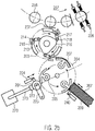
- Figure 2a shows a schematic top view of an alternative labeling device, in which the glue is applied to the labels via a pallet carousel.
- a detailed view of the gluing unit of the Figure 2a is in Figure 2b shown.
- a plurality of removal elements 205 are rotatably arranged on a rotating carrier 204 of the carousel.
- the receiving surface of each removal element 205 rolls on the glued surface of the glue roller 201, removes a label 207 from the label container 209 by adhesive action, which is glued on the rear side, and passes it on to the gripper cylinder 203, which does it transfers to the container.
- a sensor for determining a throughput of containers to be labeled can also be arranged along the inlet flow 151.
- the containers to be labeled are transferred from the infeed starwheel 254 to the turntable 258 of a carousel 257, which guides the containers past the gripper cylinder 203.
- the containers accommodated by the turntables 258 are rotated appropriately Rolling of the label to be applied fed by the gripper cylinder 203 onto the surface of the container causes.
- the label applied to the container can then be pressed onto the container with brushes 226.
- the labeled containers are transferred via an outlet star wheel 255 to an outlet stream, where an optical sensor 227 can carry out a quality control of the labeled containers.
- the label container 209 can be placed on the pallet carousel 204 via a pneumatic cylinder 240 in the labeling mode and can be disconnected from the latter in the idle mode.
- the pallets 205 of the pallet carousel 204 can be pivoted by means of a control cam (not shown) such that they are glued by the glue roller 201 and then each take up a label 207 from the label container 209.
- the glue roller 201 can be mounted on a holder 225 which can be pivoted by means of a pneumatic cylinder 224, as a result of which it can be placed on the pallet carousel 204 in the labeling mode and can be switched off from it in the idle mode.
- the glue removed from the storage container (not shown) by the removal device 270 is fed to a glue application unit 272, shown schematically here, for example in the form of a chamber glue scraper, which transfers the glue to the surface of the glue roller 201.
- the labels 207 removed from the label container 209 by the pallets 205 are transferred to the gripper cylinder 203.
- the latter removes the respective label 207 from the pallet 205 by means of a gripper finger 214 and an anvil 215, the glued side of the label 207 coming to rest on a gripper sponge 213.
- the movement of the gripper fingers 214 mounted on gripper levers 217 is brought about by the rolling off of the gripper rollers 218, which are also attached to the gripper levers 217, on a control cam 216 of the gripper cylinder 203.
- the gripper fingers 217 are opened again.
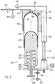
- the Figure 3 shows a cross section through a schematic representation of a device 370 for removing glue according to the present invention.
- glue is removed from a deformable storage container 380 by the action of a deformation device 350 on the storage container, as a result of which its holding volume 381 for glue is reduced.
- the pressure thus formed in the glue pushes the amount of glue to be taken out through an opening 383 in the container.
- the storage container 380 is deformed by the direct mechanical action of a deformation element 390 on the wall of the storage container.
- the deformation element 390 in this embodiment is by means of of a motor 330, which sets a spindle 331 in motion, which engages in a fixed, corresponding counter thread 332, can be moved in the longitudinal direction L relative to the reservoir 380.
- the motor 330 can be designed to be controllable and / or regulatable, so that this relative movement can be controlled and / or regulated by means of a control and / or regulating unit 339.
- the part of the removal device 370 holding the storage container 380 is fixed, while the deformation element 390 moves relative thereto. It goes without saying that the arrangement can be modified such that, alternatively or additionally, the storage container can be moved relative to the deformation element.
- the storage container 380 is connected with its opening 383, for example via a screw thread, to a connection 399 of the device. Due to the screw thread, an emptied storage container can thus be easily replaced by a filled storage container.
- the pressed-out glue is passed on to a transport line 373 which, as described above, conveys it to the glue roller or a glue printer.
- the transport line can have a control valve 387 for precise control of the amount of glue dispensed.
- a pressure sensor 386 and / or a temperature sensor 338 can be provided, which measure the pressure or the temperature of the glue in the transport line 373. The measured data can be passed on to the control and / or regulating unit 339 and can thus be incorporated into the control and / or regulation of the motor 330 of the drive device.
- the deformation element 390 is mounted on a carrier 391, a spring 392 being provided between the deformation element and the carrier, which prestresses the deformation element relative to the carrier.
- the spring 392 shown is arranged in a recess 393 of the deformation element 390.
- the deformation element 390 has a rod 394 which is guided in a guide 395 of the carrier 391.
- two sensors 396 and 397 are arranged on the carrier 391, which detect a position of a projection 398 arranged on the rod 394.
- a movement of the carrier 391 can be controlled such that the projection 398 is always between the two sensors 396 and 397.
- a predetermined force of the spring 392 can be set on the deformation element 390 and thus also a predetermined pressure on the glue located in the reservoir 380. Excessive pressure that could cause the container wall to crack can thus be effectively avoided.
- the surface of the deformation element simulating the shape of the upper part of the storage container 380 can first be brought into mechanical contact with the lower part of the storage container and then be displaced into it by further displacement.
- the storage container is deformed in such a way that the lower part of its wall is pushed into the receiving volume 381, so that a curved edge 382 of the deformed storage container 380 results.
- the wall of the storage container is pushed ever further into the interior of the storage container. As a result, almost all of the glue contained in the storage container is gradually pushed out of it.
- the shape of the storage container 380 and of the deformation element 390 can be selected in such a way that there are as few gaps as possible for glue during the deformation process. Accordingly, a stamp-shaped deformation element, as shown here, can be designed with a slightly smaller cross-sectional area than that of the storage container in order to be able to be pushed into it.
- the wall or at least the part of the wall of the storage container 380 that is to be deformed are formed from a material with a corresponding wall thickness that can be deformed by means of the force that can be exerted by the deformation device 350, for example PET. Different areas of the wall can be formed from different materials and / or with different wall thicknesses. In particular, it is desirable that the upper part of the storage container 380, which is not to be deformed, does not deform and bulge in the illustrated further development, since otherwise a complete emptying of the storage container and a controlled glue pressure cannot be guaranteed.
- the deforming device shown here has a housing 336 for receiving this part of the container, which is brought into contact with an outer surface of the non-deformable part of the container such that it encloses this part like a sleeve.
- the part of the container wall that is in direct mechanical contact with the housing 336 cannot therefore be bulged out by the increasing pressure in the receiving volume 381.
- the housing 336 can be equipped with a controllable heating and / or cooling device 335, which allows the glue located in the receiving volume 381 to be heated or cooled to an optimal processing temperature.
- the regulation of the heating and / or cooling device 335 can take place taking into account the glue temperature measured by the temperature sensor 338.
- the deformation element 390 can be designed to be stationary while the storage container 380 is moved by the drive device 330.
- the connection 399 for the opening 383 can be arranged below the storage container 380.
- the connection 399 and part of the transport line 373 as part of the deformation element 390, the transport line 373 preferably comprising at least one flexible part in the case of a moving deformation element 390.
- the shape and type of the deformation device 350 can also be adapted to the shape of the storage container described below.
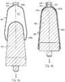
- the Figure 4 shows the deformation of the reservoir according to the present invention in two exemplary phases.
- the initially double-conical storage container 480 has already been deformed by the deformation element 490 to such an extent that the holding volume 481 for glue in the interior of the storage container 480 has been reduced to less than half.
- a large part of the glue originally contained in the storage container has already been pressed out through the opening 483 and the connection 499.
- the deformation element 490 presses part of the wall 480a of the storage container into the interior of the storage container through the deformation process.
- the curved, upper part of the deformation element 490 is shaped in such a way that it has exactly the shape of the upper part 480b of the container wall.
- the deformation element 490 is designed such that it fits snugly into the part of the storage container that is not to be deformed, the thickness of the container wall pushed into the interior being also taken into account.
- the Figure 5 shows a variety of designs of deformable storage containers for glue.
- sub-figure a) it is also in the Figures 3 and 4 Shown form of the double cone for a reservoir 580 shown.
- the container is shown schematically, with the container wall 585, the receiving volume 581 and the opening 583 of the container are explicitly designated.
- a center line M of the container is also shown. The part 585b of the container wall shown below this center line M is pushed into the part 585a of the container wall shown above the center line M by the deformation process.
- the non-deformable part 585a of the container wall 585 is designed with a greater wall thickness than the part 585b to be deformed. It can thereby be avoided that the wall element 585a, ie the part 585a of the container wall, counteracts the increase in the internal pressure in the receiving volume 581 by deformation.
- the part 585a not to be deformed can also be formed from a different, more stable material than the part 585b to be deformed.
- a variety of alternative shapes are conceivable, e.g. B. an ellipsoid or a double pyramid.
- Part c) shows an alternative embodiment of the storage container 580 in the form of a tube.
- the narrow end of the tube can be clamped between two rotatably mounted rollers 590a and 590b, which are either freely rotatable or drivable.
- the surface of the rolls can be designed with a sufficiently high coefficient of friction to pull the surface of the outer wall 585 between the rolls during the deformation process.
- the narrow end of the tube can be clamped on an element 590c which can be moved along the longitudinal direction of the tube and which pulls the tube between the two rollers.
- rollers 590a and 590b are mounted on a fixed axis, this holding space reduces the receiving volume 581 of the storage container 580, so that glue is pressed out through the opening 583.
- the rollers 590a and 590b can be designed to be movable in the longitudinal direction of the tube, the deformation of the storage container 580 being carried out by moving the rollers, which in this case are also non-rotatable, along the longitudinal direction.
- wedge-shaped elements can also be used.
- the displacement and / or rotation of the rollers 590a and 590b and the displacement of the tensioning element 590c can be controlled and / or regulated by means of the control and / or regulating unit mentioned.
- a further alternative embodiment of the storage container 580 in the form of a syringe is shown in sub-figure d).
- a cylindrical part of the container wall can be made rigid, the reduction in the receiving volume 581 being effected by moving a base element 585c of the storage container, which is also rigid. As mentioned above, this shifting also results in a deformation of the storage container.
- a rod-shaped deformation element 590d acts on the base piece 585c and is moved by means of a controllable and / or regulatable drive device.
- a tubular storage container 580 is shown, the end of which opposite the opening 583 is clamped by a tensioning element 590e of the deformation device.
- the tubular storage container 580 which can be formed in particular from a thin plastic film, is twisted so that the glue contained is pressed out through the opening 583. With this further development, too, the volume of the emptied storage container is minimized.
- Figure 6 finally shows a modular design of the removal device according to the present invention in a cabinet-like housing.
- the deformation device of which the deformation element 690 and the drive device 630 are shown only schematically, and the storage container 680 with the receiving volume 681, which has already been partially deformed in the figure, are completely enclosed by a cabinet-like housing 637, which is exemplary in the figure stands on wheels.
- the reservoir 680 is connected to the transport line 673 for the glue to be removed via a connection 699.
- Part of this transport line can be permanently connected to the housing 637 and can be provided with a connecting piece for connection to a corresponding glue line of the labeling unit. In this way, the removal module can be easily retrofitted for existing labeling machines.
- the removal module is in the Figure 6 shown in the open state for the replacement of the storage container 680.
- the cabinet-like housing 637 can have hinged or sliding door elements (not shown) which can be opened and closed as required. Seals on the door elements can ensure that the housing 637 is essentially airtight in the closed state, ie within manufacturing tolerances.
- the module can have its own control and / or regulating unit or can be connected to a control and / or regulating unit of the labeling device.
- Figure 7 is an alternative training in the Figure 2b shown labeling device, wherein instead of the glue roller 201, a controllable glue printer 741 is used to print a variable print image on the contact surface of the pallet 205.
- the glue printer 741 comprises one or more, in particular individually controllable, glue nozzles, which are arranged with respect to an orbit of the pallet 205 during their pivoting movement such that the glue jet 742 emerging from the nozzles hits the contact surface of the pallet 205.
- the glue nozzles of the glue printer 741 can be activated and deactivated individually or in groups via a control and / or regulating unit of the labeling device. Due to the pivoting movement of the pallet 205, a two-dimensional glue application is created with the glue pattern specified by the control parameters. As with the glue application unit 272, the glue printer 741 can be specifically supplied with the required amount of glue via a transport line 773 by deforming a storage container by means of the removal device 770. The glue pressure built up can at least partially be used to operate the glue nozzles.
- a glue pump or pressure booster pump with a possible media pressure of 30 to 90 bar can also be provided. It is also conceivable to use a speed mixer or twin-screw extruder to deaerate and mix the glue again.
- the described embodiments make it possible to selectively remove as much glue from a deformable storage container as is currently required to glue the labels to be applied. This prevents excess glue from running down and drying on the glue roller, so that the usual glue return can be dispensed with. Since the glue hardly comes into contact with the ambient air, the desired glue properties can be guaranteed.
- the use of compressible, interchangeable disposable containers as storage containers for the glue also allows the labeling device to be operated cleanly and easily without great maintenance and with a long service life. Disposing or recycling of the emptied containers is also simplified due to their small volume.
Landscapes
- Physics & Mathematics (AREA)
- Fluid Mechanics (AREA)
- Labeling Devices (AREA)
Claims (11)
- Dispositif d'étiquetage destiné à l'application d'étiquettes (207) sur des contenants, comprenant un dispositif d'encollage pour encoller les étiquettes, notamment avec un rouleau d'encollage (101, 201) et un réservoir de réserve (380, 480, 580, 680) pour le stockage d'approvisionnement de colle,
caractérisé par
un dispositif (170, 270, 370, 770) pour prélever de la colle du réservoir de réserve (380, 480, 580, 680) avec un dispositif de déformation (350), qui est conçu de manière telle, que de la colle soit pressée hors du réservoir de réserve (380, 480, 580, 680) par déformation du réservoir de réserve (380, 480, 580, 680) au moyen du dispositif de déformation (350) ;
le dispositif de déformation (350) présentant un élément de déformation (390, 490, 690) en forme de poinçon, qui peut être amené en contact avec le réservoir de réserve (380, 480, 580, 680), et étant conçu de manière telle, que le réservoir de réserve (380, 480, 580, 680) et l'élément de déformation (390, 490, 690) puissent être déplacés l'un par rapport à l'autre, un mouvement relatif de l'élément de déformation (390, 490, 690) et du réservoir de réserve (380, 480, 580, 680) produisant une diminution du volume d'accueil (381, 481, 581, 681) du réservoir de réserve (380, 480, 580, 680) pour la colle, grâce au fait que l'élément de déformation (390, 490, 690) repousse une partie de la paroi (480a, 585b) du réservoir de réserve (380, 480, 580, 680) dans un espace intérieur du réservoir de réserve. - Dispositif d'étiquetage selon la revendication 1, dans lequel le dispositif de déformation (350) comporte un dispositif d'entrainement (330, 630) pouvant être commandé et/ou régulé, qui produit le mouvement de l'élément de déformation (390, 490, 690) et/ou du réservoir de réserve (380, 480, 580, 680).
- Dispositif d'étiquetage selon la revendication 2, dans lequel le dispositif de déformation (350) présente par ailleurs, une unité de commande et/ou de régulation (339) programmable, qui est configurée pour commander et/ou réguler le dispositif d'entraînement (330, 630) en fonction d'au moins un paramètre de régulation, ledit au moins un paramètre de régulation étant issu du groupe qui est formé par les paramètres suivants : le type d'étiquettes à encoller, le nombre des étiquettes à encoller par unité de temps, la sorte de colle utilisée, la température de la colle utilisée, la température environnante du rouleau d'encollage (101, 201) et de la surface à encoller des étiquettes.
- Dispositif d'étiquetage selon l'une des revendications précédentes, comprenant en outre un carter (336) destiné à accueillir le réservoir de réserve (380, 480, 580, 680), dispositif d'étiquetage dans lequel le carter (336) est formé de manière à pouvoir entourer à la manière d'une douille une partie de la surface extérieure du réservoir de réserve (380, 480, 580, 680).
- Dispositif d'étiquetage selon l'une des revendications précédentes, comprenant, en outre, un dispositif de chauffage (335, 635) et/ou un dispositif de refroidissement (335, 635), qui est conçu de manière à pouvoir chauffer et/ou refroidir le réservoir de réserve (380, 480, 580, 680).
- Dispositif d'étiquetage selon la revendication 5, comprenant, en outre, un capotage (637) qui est agencé de manière à enfermer totalement le dispositif de déformation (350) et le réservoir de réserve (380, 480, 580, 680).
- Procédé destiné à l'étiquetage de contenants, d'après lequel de la colle est prélevée d'un réservoir de réserve (380, 480, 580, 680) pour le stockage de colle, et est appliquée sur des étiquettes (207), caractérisé en ce que
le prélèvement de la colle est effectué par pressage de la colle hors du réservoir de réserve (380, 480, 580, 680), par déformation du réservoir de réserve (380, 480, 580, 680) ;
en ce que la déformation du réservoir de réserve (380, 480, 580, 680) est effectuée par l'action d'un dispositif de déformation (350) sur le réservoir de réserve (380, 480, 580, 680) de configuration déformable, de manière à faire diminuer le volume d'accueil (381, 481, 581, 681) du réservoir de réserve (380, 480, 580, 680) pour la colle ;
et en ce que le volume d'accueil (381, 481, 581, 681) du réservoir de réserve (380, 480, 580, 680) est diminué par un mouvement relatif du réservoir de réserve (380, 480, 580, 680) et d'un élément de déformation (390, 490, 690) en forme de poinçon du dispositif de déformation (350) pouvant être amené en contact avec le réservoir de réserve (380, 480, 580, 680), grâce au fait que l'élément de déformation (390, 490, 690) repousse une partie de la paroi (480a, 585b) du réservoir de réserve (380, 480, 580, 680) dans un espace intérieur du réservoir de réserve. - Procédé selon la revendication 7, d'après lequel le mouvement relatif est commandé et/ou régulé de manière telle, qu'une quantité souhaitée de colle est prélevée du réservoir de réserve (380, 480, 580, 680), notamment avec une pression souhaitée.
- Procédé selon la revendication 8, d'après lequel la commande et/ou la régulation est effectuée sur la base d'au moins un paramètre de régulation issu du groupe qui est formé par les paramètres suivants : le type d'étiquettes à encoller, le nombre des étiquettes à encoller par unité de temps, la sorte de colle utilisée, la température de la colle utilisée, la température environnante d'un rouleau d'encollage (101, 201) et de la surface à encoller des étiquettes.
- Procédé selon l'une des revendications 7 à 9, comprenant, en outre, la stabilisation d'une partie d'une surface extérieure du réservoir de réserve (380, 480, 580, 680) par la mise en contact de ladite partie avec un carter (336) du dispositif de déformation (350) pour l'accueil du réservoir de réserve (380, 480, 580, 680) .
- Procédé selon l'une des revendications 7 à 10, comprenant, en outre, le chauffage et/ou le refroidissement du réservoir de réserve (380, 480, 580, 680) .
Applications Claiming Priority (2)
| Application Number | Priority Date | Filing Date | Title |
|---|---|---|---|
| DE102015212198.4A DE102015212198A1 (de) | 2015-06-30 | 2015-06-30 | Vorrichtung und Verfahren zum Leimauftrag ohne Rücklauf |
| PCT/EP2016/058046 WO2017001072A1 (fr) | 2015-06-30 | 2016-04-13 | Dispositif et procédé d'application de colle sans élément de retour |
Publications (2)
| Publication Number | Publication Date |
|---|---|
| EP3317191A1 EP3317191A1 (fr) | 2018-05-09 |
| EP3317191B1 true EP3317191B1 (fr) | 2020-01-15 |
Family
ID=55858746
Family Applications (1)
| Application Number | Title | Priority Date | Filing Date |
|---|---|---|---|
| EP16719041.2A Active EP3317191B1 (fr) | 2015-06-30 | 2016-04-13 | Dispositif et procédé pour l'approvisionnement de colle sans retour |
Country Status (5)
| Country | Link |
|---|---|
| US (1) | US20180186495A1 (fr) |
| EP (1) | EP3317191B1 (fr) |
| CN (1) | CN107709173A (fr) |
| DE (1) | DE102015212198A1 (fr) |
| WO (1) | WO2017001072A1 (fr) |
Families Citing this family (14)
| Publication number | Priority date | Publication date | Assignee | Title |
|---|---|---|---|---|
| DE102017219498A1 (de) * | 2017-11-02 | 2019-05-02 | Krones Ag | Zentrale Leimversorgung für eine Behälteretikettiermaschine |
| DE102017219496A1 (de) | 2017-11-02 | 2019-05-02 | Krones Ag | Leimversorgung für Etikettieraggregat mit Leimdrucker |
| DE102017219501A1 (de) * | 2017-11-02 | 2019-05-02 | Krones Ag | Durchflussmessung bei Leimversorgung |
| CN108580190B (zh) * | 2018-05-30 | 2023-08-01 | 江苏一控真空注胶技术有限公司 | 一种真空注胶箱 |
| DE102018216418A1 (de) * | 2018-09-26 | 2020-03-26 | Krones Ag | Leimwerk für Kaltleim |
| CN109677726B (zh) * | 2019-01-22 | 2021-01-08 | 贵州酒十分电子商务有限公司 | 瓶装产品防伪标签贴标装置 |
| DE102020101845A1 (de) * | 2020-01-27 | 2021-07-29 | Krones Aktiengesellschaft | Verfahren zum Aufspritzen von Kaltleim auf Paletten für Etiketten und Etikettieraggregat für Behälter |
| CN111664953B (zh) * | 2020-05-25 | 2022-07-22 | 黎寒英 | 一种体温计制作刻度纸辅助放置设备 |
| IT202000013375A1 (it) * | 2020-06-05 | 2021-12-05 | Scm Group Spa | Carrello perfezionato per conservare e riscaldare almeno un dispositivo di incollaggio |
| DE102020124411A1 (de) | 2020-09-18 | 2022-03-24 | Krones Aktiengesellschaft | Leimdrucker für Etikettieraggregat |
| DE102020124403A1 (de) | 2020-09-18 | 2022-03-24 | Krones Aktiengesellschaft | Verfahren zum Beleimen eines Etiketts in einer Etikettiermaschine, computerlesbares Medium und Etikettiermaschine zum Aufbringen von Etiketten auf Behältern |
| CN112756199B (zh) * | 2020-12-29 | 2022-04-15 | 宏全企业(苏州)有限公司 | 自动化可在线自检型标签料带上胶设备 |
| CN113578690A (zh) * | 2021-07-09 | 2021-11-02 | 苏州工业园区多司电子科技有限公司 | 一种供胶装置 |
| CN119284318A (zh) * | 2024-09-18 | 2025-01-10 | 江苏新美星包装机械股份有限公司 | 贴套一体装置及一种在容器上设置标签的方法 |
Family Cites Families (14)
| Publication number | Priority date | Publication date | Assignee | Title |
|---|---|---|---|---|
| DE675456C (de) * | 1938-03-17 | 1941-10-02 | Jagenberg Werke Ag | Vorrichtung zum Etikettieren von Flaschen oder aehnlichen Werkstuecken |
| GB1010543A (en) * | 1963-06-14 | 1965-11-17 | Cox & Sharland Ltd | Improvements in or relating to apparatus for applying glue and like adhesives |
| US3606095A (en) * | 1967-09-07 | 1971-09-20 | Hermann Kronseder | Feeder for high viscosity liquids |
| DE2918246A1 (de) * | 1979-05-05 | 1980-11-20 | Strunck Gmbh & Co Maschinenfab | Leimauftragsvorrichtung fuer etikettiermaschinen o.dgl. |
| DE3022040C2 (de) | 1980-06-12 | 1983-11-24 | Jagenberg-Werke AG, 4000 Düsseldorf | Verfahren zum Vorbereiten der Betriebsbereitschaftsstellung einer Etikettierstation einer Etikettiermaschine |
| EP0434617B2 (fr) * | 1989-12-19 | 1996-04-17 | Balti Ag | Dispositif d'alimentation pour des matériaux fluides, pâteux ou solides à froid, en particulier pour des adhésifs thermofusibles |
| DE4009686C2 (de) * | 1990-03-26 | 1996-07-18 | Bayerische Motoren Werke Ag | Vorrichtung zum Entleeren eines mit pastösen Medien gefüllten Foliensackes |
| DE9005193U1 (de) * | 1990-05-07 | 1991-09-05 | Geiger, Siegfried, 82178 Puchheim | Vorrichtung zum kontinuierlichen Auspressen von gasförmigen, flüssigen oder pastösen Medien aus handelsüblichen Vorratsbehältern |
| JPH06285416A (ja) * | 1993-04-02 | 1994-10-11 | Fuji Photo Film Co Ltd | 接着液供給方法及び装置 |
| JPH08215628A (ja) * | 1995-02-10 | 1996-08-27 | Matsushita Electric Ind Co Ltd | 塗布装置 |
| DE19706317C2 (de) * | 1997-02-18 | 1999-11-18 | Heydolph Gmbh | Verfahren zum Etikettieren und Etikettieranlage |
| JP5459068B2 (ja) * | 2010-05-24 | 2014-04-02 | 株式会社スリーボンド | 材料圧送装置 |
| JP5696979B2 (ja) * | 2011-02-22 | 2015-04-08 | セメダイン株式会社 | プラスチック容器、長尺状流路部材及び塗布装置 |
| DE102012101503A1 (de) * | 2012-02-24 | 2013-08-29 | Krones Ag | Entnahmeeinrichtung zur Entnahme von Flüssigkeiten aus Behältnissen |
-
2015
- 2015-06-30 DE DE102015212198.4A patent/DE102015212198A1/de not_active Withdrawn
-
2016
- 2016-04-13 EP EP16719041.2A patent/EP3317191B1/fr active Active
- 2016-04-13 WO PCT/EP2016/058046 patent/WO2017001072A1/fr not_active Ceased
- 2016-04-13 US US15/738,541 patent/US20180186495A1/en not_active Abandoned
- 2016-04-13 CN CN201680038614.6A patent/CN107709173A/zh active Pending
Non-Patent Citations (1)
| Title |
|---|
| None * |
Also Published As
| Publication number | Publication date |
|---|---|
| WO2017001072A1 (fr) | 2017-01-05 |
| CN107709173A (zh) | 2018-02-16 |
| US20180186495A1 (en) | 2018-07-05 |
| DE102015212198A1 (de) | 2017-01-05 |
| EP3317191A1 (fr) | 2018-05-09 |
Similar Documents
| Publication | Publication Date | Title |
|---|---|---|
| EP3317191B1 (fr) | Dispositif et procédé pour l'approvisionnement de colle sans retour | |
| EP3317189B1 (fr) | Dispositif et procédé pour étiqueter des récipients | |
| EP3317192B1 (fr) | Rouleau d'encollage avec zone de collage limité | |
| WO2017001076A1 (fr) | Dispositif et procédé pour étiqueter des récipients | |
| DE69811683T2 (de) | Applikation von substanzen auf eine verpackung | |
| DE69014605T2 (de) | Vorrichtung zum Füllen und Versiegeln. | |
| DE202006012400U1 (de) | Vorrichtung zum Aufbringen von Klebstoff während des Etikettiervorganges | |
| DE602004006195T2 (de) | Instandhaltung eines Tintenstrahlaufzeichnungsgerätes | |
| EP3463913B1 (fr) | Machine d'impression de feuilles | |
| DE202016105825U1 (de) | Etikettieraggregat zum Aufbringen von Formetiketten auf Behälter | |
| EP2714408A1 (fr) | Presse et procédé de réglage d'une tension de bande | |
| EP3483080A1 (fr) | Alimentation en colle pour groupe d'étiquetage pourvu d'un applicateur de colle | |
| WO2007124913A1 (fr) | Procédé de préparation d'emballages lors de l'emballage d'un matériau de remplissage ou d'emballage et dispositif de mise en œuvre du procédé | |
| EP3088090B1 (fr) | Dispositif de laquage et procédé de laquage d'une surface extérieure d'un objet laqué | |
| WO2009071237A1 (fr) | Procédé d'étiquetage de récipients et poste d'étiquetage | |
| EP3880561B1 (fr) | Dispositif et procédé de fabrication d'un groupe de récipients | |
| EP2495365B1 (fr) | Dispositif de préparation de couches intermédiaires, procédé de palettisation | |
| EP0404088A2 (fr) | Dispositif pour alimenter un encrier dans une machine à imprimer | |
| EP3486184B1 (fr) | Mesure de débit lors de l'alimentation en colle | |
| WO2017025218A1 (fr) | Procédé et dispositif pour raccorder des étiquettes tubulaires | |
| DE102006047488A1 (de) | Verpackungsmaschine mit einer Etikettierungsvorrichtung | |
| WO2022058052A1 (fr) | Imprimante à colle pour étiqueteuse | |
| EP2623425B1 (fr) | Dispositif et procédé destinés à l'étiquetage d'objets | |
| WO2017001073A1 (fr) | Dispositif et procédé d'étiquetage de récipients | |
| DE4019608A1 (de) | Vorrichtung zur beschickung eines farbkastens an einer druckmaschine |
Legal Events
| Date | Code | Title | Description |
|---|---|---|---|
| STAA | Information on the status of an ep patent application or granted ep patent |
Free format text: STATUS: THE INTERNATIONAL PUBLICATION HAS BEEN MADE |
|
| PUAI | Public reference made under article 153(3) epc to a published international application that has entered the european phase |
Free format text: ORIGINAL CODE: 0009012 |
|
| STAA | Information on the status of an ep patent application or granted ep patent |
Free format text: STATUS: REQUEST FOR EXAMINATION WAS MADE |
|
| 17P | Request for examination filed |
Effective date: 20170718 |
|
| AK | Designated contracting states |
Kind code of ref document: A1 Designated state(s): AL AT BE BG CH CY CZ DE DK EE ES FI FR GB GR HR HU IE IS IT LI LT LU LV MC MK MT NL NO PL PT RO RS SE SI SK SM TR |
|
| AX | Request for extension of the european patent |
Extension state: BA ME |
|
| DAV | Request for validation of the european patent (deleted) | ||
| DAX | Request for extension of the european patent (deleted) | ||
| GRAP | Despatch of communication of intention to grant a patent |
Free format text: ORIGINAL CODE: EPIDOSNIGR1 |
|
| STAA | Information on the status of an ep patent application or granted ep patent |
Free format text: STATUS: GRANT OF PATENT IS INTENDED |
|
| INTG | Intention to grant announced |
Effective date: 20191021 |
|
| GRAS | Grant fee paid |
Free format text: ORIGINAL CODE: EPIDOSNIGR3 |
|
| GRAA | (expected) grant |
Free format text: ORIGINAL CODE: 0009210 |
|
| STAA | Information on the status of an ep patent application or granted ep patent |
Free format text: STATUS: THE PATENT HAS BEEN GRANTED |
|
| AK | Designated contracting states |
Kind code of ref document: B1 Designated state(s): AL AT BE BG CH CY CZ DE DK EE ES FI FR GB GR HR HU IE IS IT LI LT LU LV MC MK MT NL NO PL PT RO RS SE SI SK SM TR |
|
| REG | Reference to a national code |
Ref country code: CH Ref legal event code: EP Ref country code: GB Ref legal event code: FG4D Free format text: NOT ENGLISH |
|
| REG | Reference to a national code |
Ref country code: IE Ref legal event code: FG4D Free format text: LANGUAGE OF EP DOCUMENT: GERMAN |
|
| REG | Reference to a national code |
Ref country code: DE Ref legal event code: R096 Ref document number: 502016008445 Country of ref document: DE |
|
| REG | Reference to a national code |
Ref country code: AT Ref legal event code: REF Ref document number: 1224965 Country of ref document: AT Kind code of ref document: T Effective date: 20200215 |
|
| REG | Reference to a national code |
Ref country code: NL Ref legal event code: MP Effective date: 20200115 |
|
| REG | Reference to a national code |
Ref country code: LT Ref legal event code: MG4D |
|
| PG25 | Lapsed in a contracting state [announced via postgrant information from national office to epo] |
Ref country code: NL Free format text: LAPSE BECAUSE OF FAILURE TO SUBMIT A TRANSLATION OF THE DESCRIPTION OR TO PAY THE FEE WITHIN THE PRESCRIBED TIME-LIMIT Effective date: 20200115 Ref country code: RS Free format text: LAPSE BECAUSE OF FAILURE TO SUBMIT A TRANSLATION OF THE DESCRIPTION OR TO PAY THE FEE WITHIN THE PRESCRIBED TIME-LIMIT Effective date: 20200115 Ref country code: PT Free format text: LAPSE BECAUSE OF FAILURE TO SUBMIT A TRANSLATION OF THE DESCRIPTION OR TO PAY THE FEE WITHIN THE PRESCRIBED TIME-LIMIT Effective date: 20200607 Ref country code: FI Free format text: LAPSE BECAUSE OF FAILURE TO SUBMIT A TRANSLATION OF THE DESCRIPTION OR TO PAY THE FEE WITHIN THE PRESCRIBED TIME-LIMIT Effective date: 20200115 Ref country code: NO Free format text: LAPSE BECAUSE OF FAILURE TO SUBMIT A TRANSLATION OF THE DESCRIPTION OR TO PAY THE FEE WITHIN THE PRESCRIBED TIME-LIMIT Effective date: 20200415 |
|
| PG25 | Lapsed in a contracting state [announced via postgrant information from national office to epo] |
Ref country code: GR Free format text: LAPSE BECAUSE OF FAILURE TO SUBMIT A TRANSLATION OF THE DESCRIPTION OR TO PAY THE FEE WITHIN THE PRESCRIBED TIME-LIMIT Effective date: 20200416 Ref country code: BG Free format text: LAPSE BECAUSE OF FAILURE TO SUBMIT A TRANSLATION OF THE DESCRIPTION OR TO PAY THE FEE WITHIN THE PRESCRIBED TIME-LIMIT Effective date: 20200415 Ref country code: IS Free format text: LAPSE BECAUSE OF FAILURE TO SUBMIT A TRANSLATION OF THE DESCRIPTION OR TO PAY THE FEE WITHIN THE PRESCRIBED TIME-LIMIT Effective date: 20200515 Ref country code: SE Free format text: LAPSE BECAUSE OF FAILURE TO SUBMIT A TRANSLATION OF THE DESCRIPTION OR TO PAY THE FEE WITHIN THE PRESCRIBED TIME-LIMIT Effective date: 20200115 Ref country code: HR Free format text: LAPSE BECAUSE OF FAILURE TO SUBMIT A TRANSLATION OF THE DESCRIPTION OR TO PAY THE FEE WITHIN THE PRESCRIBED TIME-LIMIT Effective date: 20200115 Ref country code: LV Free format text: LAPSE BECAUSE OF FAILURE TO SUBMIT A TRANSLATION OF THE DESCRIPTION OR TO PAY THE FEE WITHIN THE PRESCRIBED TIME-LIMIT Effective date: 20200115 |
|
| REG | Reference to a national code |
Ref country code: DE Ref legal event code: R097 Ref document number: 502016008445 Country of ref document: DE |
|
| PG25 | Lapsed in a contracting state [announced via postgrant information from national office to epo] |
Ref country code: SM Free format text: LAPSE BECAUSE OF FAILURE TO SUBMIT A TRANSLATION OF THE DESCRIPTION OR TO PAY THE FEE WITHIN THE PRESCRIBED TIME-LIMIT Effective date: 20200115 Ref country code: EE Free format text: LAPSE BECAUSE OF FAILURE TO SUBMIT A TRANSLATION OF THE DESCRIPTION OR TO PAY THE FEE WITHIN THE PRESCRIBED TIME-LIMIT Effective date: 20200115 Ref country code: SK Free format text: LAPSE BECAUSE OF FAILURE TO SUBMIT A TRANSLATION OF THE DESCRIPTION OR TO PAY THE FEE WITHIN THE PRESCRIBED TIME-LIMIT Effective date: 20200115 Ref country code: DK Free format text: LAPSE BECAUSE OF FAILURE TO SUBMIT A TRANSLATION OF THE DESCRIPTION OR TO PAY THE FEE WITHIN THE PRESCRIBED TIME-LIMIT Effective date: 20200115 Ref country code: RO Free format text: LAPSE BECAUSE OF FAILURE TO SUBMIT A TRANSLATION OF THE DESCRIPTION OR TO PAY THE FEE WITHIN THE PRESCRIBED TIME-LIMIT Effective date: 20200115 Ref country code: CZ Free format text: LAPSE BECAUSE OF FAILURE TO SUBMIT A TRANSLATION OF THE DESCRIPTION OR TO PAY THE FEE WITHIN THE PRESCRIBED TIME-LIMIT Effective date: 20200115 Ref country code: LT Free format text: LAPSE BECAUSE OF FAILURE TO SUBMIT A TRANSLATION OF THE DESCRIPTION OR TO PAY THE FEE WITHIN THE PRESCRIBED TIME-LIMIT Effective date: 20200115 Ref country code: ES Free format text: LAPSE BECAUSE OF FAILURE TO SUBMIT A TRANSLATION OF THE DESCRIPTION OR TO PAY THE FEE WITHIN THE PRESCRIBED TIME-LIMIT Effective date: 20200115 |
|
| PLBE | No opposition filed within time limit |
Free format text: ORIGINAL CODE: 0009261 |
|
| STAA | Information on the status of an ep patent application or granted ep patent |
Free format text: STATUS: NO OPPOSITION FILED WITHIN TIME LIMIT |
|
| PG25 | Lapsed in a contracting state [announced via postgrant information from national office to epo] |
Ref country code: MC Free format text: LAPSE BECAUSE OF FAILURE TO SUBMIT A TRANSLATION OF THE DESCRIPTION OR TO PAY THE FEE WITHIN THE PRESCRIBED TIME-LIMIT Effective date: 20200115 |
|
| REG | Reference to a national code |
Ref country code: CH Ref legal event code: PL |
|
| 26N | No opposition filed |
Effective date: 20201016 |
|
| PG25 | Lapsed in a contracting state [announced via postgrant information from national office to epo] |
Ref country code: CH Free format text: LAPSE BECAUSE OF NON-PAYMENT OF DUE FEES Effective date: 20200430 Ref country code: LU Free format text: LAPSE BECAUSE OF NON-PAYMENT OF DUE FEES Effective date: 20200413 Ref country code: LI Free format text: LAPSE BECAUSE OF NON-PAYMENT OF DUE FEES Effective date: 20200430 |
|
| REG | Reference to a national code |
Ref country code: BE Ref legal event code: MM Effective date: 20200430 |
|
| PG25 | Lapsed in a contracting state [announced via postgrant information from national office to epo] |
Ref country code: SI Free format text: LAPSE BECAUSE OF FAILURE TO SUBMIT A TRANSLATION OF THE DESCRIPTION OR TO PAY THE FEE WITHIN THE PRESCRIBED TIME-LIMIT Effective date: 20200115 Ref country code: BE Free format text: LAPSE BECAUSE OF NON-PAYMENT OF DUE FEES Effective date: 20200430 Ref country code: PL Free format text: LAPSE BECAUSE OF FAILURE TO SUBMIT A TRANSLATION OF THE DESCRIPTION OR TO PAY THE FEE WITHIN THE PRESCRIBED TIME-LIMIT Effective date: 20200115 |
|
| GBPC | Gb: european patent ceased through non-payment of renewal fee |
Effective date: 20200415 |
|
| PG25 | Lapsed in a contracting state [announced via postgrant information from national office to epo] |
Ref country code: GB Free format text: LAPSE BECAUSE OF NON-PAYMENT OF DUE FEES Effective date: 20200415 Ref country code: IE Free format text: LAPSE BECAUSE OF NON-PAYMENT OF DUE FEES Effective date: 20200413 |
|
| PG25 | Lapsed in a contracting state [announced via postgrant information from national office to epo] |
Ref country code: TR Free format text: LAPSE BECAUSE OF FAILURE TO SUBMIT A TRANSLATION OF THE DESCRIPTION OR TO PAY THE FEE WITHIN THE PRESCRIBED TIME-LIMIT Effective date: 20200115 Ref country code: MT Free format text: LAPSE BECAUSE OF FAILURE TO SUBMIT A TRANSLATION OF THE DESCRIPTION OR TO PAY THE FEE WITHIN THE PRESCRIBED TIME-LIMIT Effective date: 20200115 Ref country code: CY Free format text: LAPSE BECAUSE OF FAILURE TO SUBMIT A TRANSLATION OF THE DESCRIPTION OR TO PAY THE FEE WITHIN THE PRESCRIBED TIME-LIMIT Effective date: 20200115 |
|
| REG | Reference to a national code |
Ref country code: AT Ref legal event code: MM01 Ref document number: 1224965 Country of ref document: AT Kind code of ref document: T Effective date: 20210413 |
|
| PG25 | Lapsed in a contracting state [announced via postgrant information from national office to epo] |
Ref country code: MK Free format text: LAPSE BECAUSE OF FAILURE TO SUBMIT A TRANSLATION OF THE DESCRIPTION OR TO PAY THE FEE WITHIN THE PRESCRIBED TIME-LIMIT Effective date: 20200115 Ref country code: AL Free format text: LAPSE BECAUSE OF FAILURE TO SUBMIT A TRANSLATION OF THE DESCRIPTION OR TO PAY THE FEE WITHIN THE PRESCRIBED TIME-LIMIT Effective date: 20200115 |
|
| PG25 | Lapsed in a contracting state [announced via postgrant information from national office to epo] |
Ref country code: AT Free format text: LAPSE BECAUSE OF NON-PAYMENT OF DUE FEES Effective date: 20210413 |
|
| PGFP | Annual fee paid to national office [announced via postgrant information from national office to epo] |
Ref country code: IT Payment date: 20240313 Year of fee payment: 9 Ref country code: FR Payment date: 20240308 Year of fee payment: 9 |
|
| PGFP | Annual fee paid to national office [announced via postgrant information from national office to epo] |
Ref country code: DE Payment date: 20240306 Year of fee payment: 9 |
|
| REG | Reference to a national code |
Ref country code: DE Ref legal event code: R119 Ref document number: 502016008445 Country of ref document: DE |
|
| PG25 | Lapsed in a contracting state [announced via postgrant information from national office to epo] |
Ref country code: DE Free format text: LAPSE BECAUSE OF NON-PAYMENT OF DUE FEES Effective date: 20251104 |
|
| PG25 | Lapsed in a contracting state [announced via postgrant information from national office to epo] |
Ref country code: FR Free format text: LAPSE BECAUSE OF NON-PAYMENT OF DUE FEES Effective date: 20250430 |
|
| PG25 | Lapsed in a contracting state [announced via postgrant information from national office to epo] |
Ref country code: IT Free format text: LAPSE BECAUSE OF NON-PAYMENT OF DUE FEES Effective date: 20250413 |