EP3317546B1 - Fluidisches bauteil - Google Patents
Fluidisches bauteil Download PDFInfo
- Publication number
- EP3317546B1 EP3317546B1 EP16798135.6A EP16798135A EP3317546B1 EP 3317546 B1 EP3317546 B1 EP 3317546B1 EP 16798135 A EP16798135 A EP 16798135A EP 3317546 B1 EP3317546 B1 EP 3317546B1
- Authority
- EP
- European Patent Office
- Prior art keywords
- component
- outlet
- flow
- outlet opening
- fluidic component
- Prior art date
- Legal status (The legal status is an assumption and is not a legal conclusion. Google has not performed a legal analysis and makes no representation as to the accuracy of the status listed.)
- Active
Links
Images


Classifications
-
- B—PERFORMING OPERATIONS; TRANSPORTING
- B05—SPRAYING OR ATOMISING IN GENERAL; APPLYING FLUENT MATERIALS TO SURFACES, IN GENERAL
- B05B—SPRAYING APPARATUS; ATOMISING APPARATUS; NOZZLES
- B05B1/00—Nozzles, spray heads or other outlets, with or without auxiliary devices such as valves, heating means
- B05B1/02—Nozzles, spray heads or other outlets, with or without auxiliary devices such as valves, heating means designed to produce a jet, spray, or other discharge of particular shape or nature, e.g. in single drops, or having an outlet of particular shape
- B05B1/08—Nozzles, spray heads or other outlets, with or without auxiliary devices such as valves, heating means designed to produce a jet, spray, or other discharge of particular shape or nature, e.g. in single drops, or having an outlet of particular shape of pulsating nature, e.g. delivering liquid in successive separate quantities
-
- B—PERFORMING OPERATIONS; TRANSPORTING
- B05—SPRAYING OR ATOMISING IN GENERAL; APPLYING FLUENT MATERIALS TO SURFACES, IN GENERAL
- B05B—SPRAYING APPARATUS; ATOMISING APPARATUS; NOZZLES
- B05B1/00—Nozzles, spray heads or other outlets, with or without auxiliary devices such as valves, heating means
- B05B1/34—Nozzles, spray heads or other outlets, with or without auxiliary devices such as valves, heating means designed to influence the nature of flow of the liquid or other fluent material, e.g. to produce swirl
-
- B—PERFORMING OPERATIONS; TRANSPORTING
- B05—SPRAYING OR ATOMISING IN GENERAL; APPLYING FLUENT MATERIALS TO SURFACES, IN GENERAL
- B05B—SPRAYING APPARATUS; ATOMISING APPARATUS; NOZZLES
- B05B1/00—Nozzles, spray heads or other outlets, with or without auxiliary devices such as valves, heating means
- B05B1/02—Nozzles, spray heads or other outlets, with or without auxiliary devices such as valves, heating means designed to produce a jet, spray, or other discharge of particular shape or nature, e.g. in single drops, or having an outlet of particular shape
-
- B—PERFORMING OPERATIONS; TRANSPORTING
- B05—SPRAYING OR ATOMISING IN GENERAL; APPLYING FLUENT MATERIALS TO SURFACES, IN GENERAL
- B05B—SPRAYING APPARATUS; ATOMISING APPARATUS; NOZZLES
- B05B7/00—Spraying apparatus for discharge of liquids or other fluent materials from two or more sources, e.g. of liquid and air, of powder and gas
- B05B7/02—Spray pistols; Apparatus for discharge
- B05B7/04—Spray pistols; Apparatus for discharge with arrangements for mixing liquids or other fluent materials before discharge
-
- B—PERFORMING OPERATIONS; TRANSPORTING
- B08—CLEANING
- B08B—CLEANING IN GENERAL; PREVENTION OF FOULING IN GENERAL
- B08B3/00—Cleaning by methods involving the use or presence of liquid or steam
- B08B3/02—Cleaning by the force of jets or sprays
-
- F—MECHANICAL ENGINEERING; LIGHTING; HEATING; WEAPONS; BLASTING
- F02—COMBUSTION ENGINES; HOT-GAS OR COMBUSTION-PRODUCT ENGINE PLANTS
- F02M—SUPPLYING COMBUSTION ENGINES IN GENERAL WITH COMBUSTIBLE MIXTURES OR CONSTITUENTS THEREOF
- F02M61/00—Fuel-injectors not provided for in groups F02M39/00 - F02M57/00 or F02M67/00
- F02M61/16—Details not provided for in, or of interest apart from, the apparatus of groups F02M61/02 - F02M61/14
- F02M61/18—Injection nozzles, e.g. having valve seats; Details of valve member seated ends, not otherwise provided for
- F02M61/1806—Injection nozzles, e.g. having valve seats; Details of valve member seated ends, not otherwise provided for characterised by the arrangement of discharge orifices, e.g. orientation or size
- F02M61/1846—Dimensional characteristics of discharge orifices
-
- F—MECHANICAL ENGINEERING; LIGHTING; HEATING; WEAPONS; BLASTING
- F15—FLUID-PRESSURE ACTUATORS; HYDRAULICS OR PNEUMATICS IN GENERAL
- F15B—SYSTEMS ACTING BY MEANS OF FLUIDS IN GENERAL; FLUID-PRESSURE ACTUATORS, e.g. SERVOMOTORS; DETAILS OF FLUID-PRESSURE SYSTEMS, NOT OTHERWISE PROVIDED FOR
- F15B21/00—Common features of fluid actuator systems; Fluid-pressure actuator systems or details thereof, not covered by any other group of this subclass
- F15B21/12—Fluid oscillators or pulse generators
-
- B—PERFORMING OPERATIONS; TRANSPORTING
- B05—SPRAYING OR ATOMISING IN GENERAL; APPLYING FLUENT MATERIALS TO SURFACES, IN GENERAL
- B05B—SPRAYING APPARATUS; ATOMISING APPARATUS; NOZZLES
- B05B1/00—Nozzles, spray heads or other outlets, with or without auxiliary devices such as valves, heating means
- B05B1/02—Nozzles, spray heads or other outlets, with or without auxiliary devices such as valves, heating means designed to produce a jet, spray, or other discharge of particular shape or nature, e.g. in single drops, or having an outlet of particular shape
- B05B1/10—Nozzles, spray heads or other outlets, with or without auxiliary devices such as valves, heating means designed to produce a jet, spray, or other discharge of particular shape or nature, e.g. in single drops, or having an outlet of particular shape in the form of a fine jet, e.g. for use in wind-screen washers
Definitions
- the invention relates to a fluidic component according to the preamble of claim 1 and to a cleaning device which comprises such a fluidic component.
- the fluidic component is provided for generating a moving fluid jet.
- Exemplary fluidic components are, for example, from US 2013/240644 A1 , EP 1 472 966 A2 , US 2007/295840 A1 and US 2004/251315 A1 known.
- nozzles For generating a fluid jet at high speed or high impulse, nozzles are known from the prior art which are designed to apply a pressure to the fluid jet which is higher than the ambient pressure.
- the fluid is accelerated and / or directed or bundled by means of the nozzle.
- the nozzle In order to generate a movement of a fluid jet, the nozzle is usually moved by means of a device.
- an additional device is required in addition to the nozzle. This additional device includes moving components that can easily wear out. The costs associated with production and maintenance are correspondingly high.
- Another disadvantage is that, due to the movable components, a relatively large overall space is required.
- Fluidic components are also known for generating a movable fluid flow (or fluid jet).
- the fluidic components do not include any movable components that are used to generate a movable fluid flow.
- a strong pressure gradient occurs regularly, so that cavitation, i.e. the formation of cavities (bubbles), can occur when a liquid fluid flow flows through the fluidic components. This can massively reduce the service life of the components or cause the fluidic components to fail.
- the known fluidic components are also more suitable for wetting surfaces than for generating a fluid jet at high speed or with high momentum. For example, a fluid flow emerging from a known fluidic component has the spray characteristics of a flat jet nozzle which generates a finely atomized jet.
- the present invention is based on the object of creating a fluidic component that is designed to provide a moving fluid jet at high speed or high pressure, the fluidic component having a high level of failure safety and correspondingly lower maintenance costs.
- the fluidic component comprises a flow chamber through which a fluid flow can flow.
- the fluid flow can be a liquid flow or a gas flow.
- the flow chamber comprises an inlet opening and an outlet opening through which the fluid flow enters the flow chamber or exits the flow chamber again.
- the fluidic component further comprises at least one means for the targeted change of direction of the fluid flow at the outlet opening, the means being designed in particular to form a spatial oscillation of the fluid flow at the outlet opening.
- the flow chamber has a main flow channel which connects the inlet opening and the outlet opening to one another, and at least one secondary flow channel as the at least one means for the targeted change in direction of the fluid flow at the outlet opening.
- the fluidic component is characterized in that the inlet opening has a larger cross-sectional area than the outlet opening or that the inlet opening and the outlet opening have the same cross-sectional area.
- the cross-sectional areas of the inlet opening and the outlet opening are to be understood to mean the smallest cross-sectional areas of the fluidic component that the fluid flow passes when it enters the flow chamber or exits the flow chamber again.
- Movable components for generating an oscillating beam can be dispensed with in the arrangement according to the invention, so that costs and expenditures caused by this do not arise.
- the development of vibration and noise in the fluidic component according to the invention is relatively low.
- the spatially oscillating fluid jet which emerges from the fluidic component according to the invention has a high removal and cleaning capacity due to its compactness and high speed when it is directed onto a surface.
- the fluidic component according to the invention can therefore be used, for example, in cleaning technology.
- the fluidic component according to the invention is also of interest for mixing technology (in which two or more different fluids are to be mixed with one another) and production technology (for example water jet cutting). For example, the effectiveness of water jet cutting can be increased with a pulsating fluid jet emerging from the fluidic component according to the invention.
- the cross-sectional area of the inlet opening can be the same size as or larger than the cross-sectional area of the outlet opening.
- the size ratio can be selected depending on the desired characteristics (speed or pulse, compactness, oscillation frequency) of the emerging beam. However, other parameters, such as the size (for example the volume and / or the component depth, component width, component length) of the fluidic component, the shape of the fluidic component, the type of fluid (gas, liquid with low viscosity, liquid with high Viscosity), the size of the pressure with which the fluid flow enters the fluidic component, the input speed of the fluid and the volume flow influence the choice of the size ratio.
- the oscillation frequency can be between 0.5 Hz and 30 kHz.
- a preferred frequency range is between 3 Hz and 400 Hz.
- the inlet pressure can be between 0.01 bar and 6000 bar above ambient pressure.
- the inlet pressure is typically between 0.01 bar and 12 bar above the ambient pressure.
- high pressure applications such as cleaning (of vehicles, semi-finished products, machines or stables) or the mixing of two different fluids, the inlet pressure is typically between 5 bar and 300 bar.
- the cross-sectional area of the inlet opening can be larger by a factor of up to 2.5 than the cross-sectional area of the outlet opening. According to a particularly preferred embodiment, the cross-sectional area of the inlet opening can be a factor of up to 1.5 larger than the cross-sectional area of the outlet opening.
- the cross-sectional area of the outlet opening can have any shape, such as square, rectangular, polygonal, round, oval, etc., for example. The same applies to the cross-sectional area of the inlet opening.
- the shape of the inlet opening can correspond to the shape of the outlet opening or differ from the latter.
- a round cross-sectional area of the outlet opening can be selected, for example, in order to generate a particularly compact / bundled fluid jet. Such a fluid jet can be used in particular in high-pressure cleaning technology or in water jet cutting.
- both the inlet opening and the outlet opening have a rectangular cross section.
- the inlet opening can have a greater width than the outlet opening.
- the width of the inlet and outlet opening is defined in relation to the geometry of the fluidic component.
- the fluidic component can, for example, be essentially cuboid and accordingly have a component length, a component width and a component depth, the component length determining the distance between the inlet opening and the outlet opening and the component width and the component depth being defined perpendicular to each other and to the component length and where the component width is greater than the component depth.
- the component length thus extends essentially parallel to the main direction of propagation of the fluid flow, which is intended to move from the inlet opening to the outlet opening. If the inlet and outlet openings lie on an axis that extends parallel to the component length, the distance between the inlet and outlet openings corresponds to the component length.
- the inlet and outlet openings are arranged offset from one another, said opening extends If the axis is at an angle not equal to 0 ° to the component length, the component length and the offset of the inlet and outlet openings determine the distance between the inlet and outlet openings along the axis.
- the ratio of component length to component width can be 1/3 to 5. The ratio is preferably in the range from 1/1 to 4/1.
- the component width can be in the range between 0.15 mm and 2.5 m. In a preferred embodiment, the component width is between 1.5 mm and 200 mm. The dimensions mentioned depend in particular on the application for which the fluidic component is to be used.
- a substantially cuboid fluidic component can have a rectangular outlet opening with a width that corresponds to 1/3 to 1/50 of the component width, and a rectangular inlet opening with a width that corresponds to 1/3 to 1/20 of the component width.
- the width of the outlet opening can correspond to 1/5 to 1/15 of the component width and the width of the inlet opening 1/5 to 1/10 of the component width.
- the ratio of the component depth to the width of the inlet opening can be 1/20 to 5. This ratio is also known as the aspect ratio.
- a preferred aspect ratio is between 1/6 and 2.
- the size ratios mentioned also depend in particular on the application for which the fluidic component is to be used.
- the fluidic component has a component depth that is constant over the entire component length.
- the component depth can decrease (steadily (with or without constant increase) or abruptly) from the inlet opening towards the outlet opening. Due to the decreasing component depth, the fluid jet is pre-bundled within the fluidic component, so that a compact fluid jet emerges from the fluidic component. A widening or bursting of the fluid jet can thus be delayed and thus does not take place directly at the outlet opening, but only further downstream. This measure is advantageous, for example, in cleaning technology or in water jet technology.
- the component depth can increase from the inlet opening to the outlet opening, the component width decreasing such that the cross-sectional area of the outlet opening is smaller than or equal to the cross-sectional area of the inlet opening.
- the flow chamber has at least one secondary flow channel as a means for the targeted change in direction of the fluid flow at the outlet opening.
- the secondary flow channel can be flowed through by part of the fluid flow, the secondary flow.
- the part of the fluid flow which does not enter the secondary flow channel but exits the fluidic component is referred to as the main flow.
- the at least one bypass duct can have an inlet that is located in the vicinity of the outlet opening and an outlet that is located in the vicinity of the inlet opening.
- the at least one secondary flow channel can be arranged next to (not behind or in front of) the main flow channel when viewed in the fluid flow direction (from the inlet opening to the outlet opening).
- two secondary flow channels can be provided which (viewed in the main flow direction) extend laterally next to the main flow channel, the main flow channel being arranged between the two secondary flow channels.
- the secondary flow channels and the main flow channel are arranged in a row along the width of the component and each extend along the length of the component.
- the secondary flow ducts and the main flow duct can be arranged in a row along the component depth and each extend along the component length.
- the at least one secondary flow channel is preferably separated from the main flow channel by a block.
- This block can have different shapes.
- the cross section of the block can taper in the direction of the fluid flow (from the inlet opening to the outlet opening).
- the cross section of the block can taper or increase in the middle between its end facing the inlet opening and its end facing the outlet opening. It is also possible to enlarge the cross section of the block as the distance from the inlet opening increases.
- the block can have rounded edges. Sharp edges can be provided on the block in particular in the vicinity of the inlet opening and / or the outlet opening.
- the at least one secondary flow channel can have a greater or smaller depth than the main flow channel.
- the oscillation frequency of the exiting fluid jet can also be influenced.
- the oscillation frequency drops if the other parameters remain essentially unchanged.
- the oscillation frequency increases accordingly if the component depth in the area of the at least one secondary flow channel is increased (compared to the main flow channel) and the other parameters remain essentially unchanged.
- a separator is to be understood as an element projecting into the flow chamber (transversely to the flow direction prevailing in the bypass duct) at the inlet of the at least one bypass duct.
- the separator can be provided as a deformation (in particular an indentation) of the secondary flow duct wall or as a projection formed in some other way.
- the separator (circle) can be conical or pyramidal. The use of such a separator makes it possible not only to influence the oscillation frequency but also to vary the so-called oscillation angle.
- the angle of oscillation is the angle that the oscillating fluid jet sweeps (between its two maximum deflections). If several secondary flow channels are provided, a separator can be provided for each of the secondary flow channels or only for some of the secondary flow channels.
- an outlet channel can be provided directly upstream of the outlet opening.
- the outlet channel can have a cross-sectional shape which is constant over the entire length of the outlet channel and which corresponds to the shape of the cross-sectional area of the outlet opening (square, rectangular, polygonal, round, etc.).
- the shape of the cross-sectional area of the outlet channel can change over the length of the outlet channel.
- the size of the cross-sectional area of the outlet opening can remain constant (that is then also the size of the outlet opening) or change. In particular, the size of the cross-sectional area of the outlet channel in the fluid flow direction from the inlet opening to the outlet opening can be reduced.
- the shape and / or size of the cross-sectional area of the main flow channel can change from the inlet opening to the outlet opening.
- the shape of the cross-sectional area (of the outlet channel or of the main flow channel) can change from rectangular to round (in the fluid flow direction from the inlet opening to the outlet opening).
- the fluid jet can already be pre-bundled in the fluidic component, so that the compactness of the exiting fluid jet can be increased.
- the size of the cross-sectional area of the outlet channel can change, in particular decrease in the fluid flow direction from the inlet opening to the outlet opening.
- the shape of the outlet channel influences the angle of oscillation of the exiting fluid jet and can be selected so that a desired angle of oscillation is established.
- the outlet channel can be designed as a further feature to be straight or curved.
- the parameters of the fluidic component can be set in a variety of ways. These parameters are preferably selected in such a way that the pressure with which the fluid flow is acted upon and enters the fluidic component via the inlet opening is substantially reduced at the outlet opening. A slight pressure reduction that occurs at the outlet opening can already take place in the fluidic component (upstream of the outlet opening).
- the fluidic component has two or more outlet openings. These outlet openings can be formed by arranging a flow divider immediately upstream of the outlet openings.
- the flow divider is a means for splitting the fluid flow into two or more sub-flows.
- each outlet opening can each have a smaller cross-sectional area than the inlet opening or all outlet openings and the inlet opening can each have an equally large cross-sectional area.
- only one of the two / more outlet openings can also have a smaller / equal cross-sectional area than / like the inlet opening.
- a fluidic component with two or more outlet openings is suitable for generating two or more fluid jets which emerge from the fluidic component in a pulsating manner over time. A (minimal) local oscillation can occur within a pulse.
- the flow divider can have different shapes, but they all have in common that they widen downstream in the plane in which the exiting fluid jet oscillates and transversely to the longitudinal axis of the fluidic component.
- the flow divider can be arranged in the outlet channel (if present).
- the flow divider can extend deeper into the fluidic component, for example into the main flow channel.
- the flow divider can be arranged symmetrically (with respect to an axis that extends parallel to the component length) in such a way that the outlet openings are identical in shape and size.
- other positions are also possible, which can be selected as a function of the desired pulse characteristics of the exiting fluid jets.
- the fluidic component comprises a fluid flow guide which is arranged downstream in connection with the outlet opening.
- the fluid flow guide is essentially tubular (for example with a constant large cross-sectional area and constant cross-sectional area shape) and is movable by the fluid flow changing its direction.
- the cross-sectional area of the fluid flow guide can correspond to the cross-sectional area of the outlet opening.
- the movement of the fluid flow guide has no influence on the direction of the exiting fluid flow.
- the fluid flow guide merely represents a means (passive component) for the additional bundling of the oscillating exiting fluid jet.
- the fluid flow bundled in this way fans out or bursts further downstream than a fluid flow emerging from a fluid component without fluid flow guide. This property can be particularly desirable in cleaning technology.
- a bearing can be provided, for example, via which the fluid flow guide is movably attached to the outlet opening.
- Different joint designs are known from practice, which can be used in principle.
- a ball joint or a solid body joint is possible.
- the fluid flow guide and / or the mounting can be made of an elastic material.
- the cross-sectional area of the outlet opening of the fluid flow guide can also be implemented differently.
- the outlet opening of the fluid flow guide is the opening from which the fluid flow exits from the fluid flow guide (and thus from the fluidic component). Shapes for the cross-sectional area of the outlet opening of the fluid flow guide, which were described in connection with the outlet opening of the fluidic component without a fluid flow guide, are thus possible.
- the shape of the cross-sectional area of the fluid flow guide can also change over the length of the fluid flow guide.
- a rectangular cross-sectional area can be provided in the area of the bearing (that is to say at the inlet of the fluid flow guide), which merges into a round cross-sectional area downstream.
- the fluidic component has an outlet widening which adjoins the outlet opening downstream of the outlet opening.
- the outlet widening connects directly (directly) to the outlet opening downstream of the outlet opening.
- the outlet widening can, for example, be funnel-shaped.
- the outlet widening can have a cross-sectional area (perpendicular to the fluid flow direction) have, the size of which increases from the outlet opening downstream.
- the outlet opening can form the point with the smallest cross-sectional area between the flow chamber and the outlet widening.
- the outlet widening can serve to bundle a fluid jet which experiences a high pressure reduction at the outlet opening and thus bursts open at the outlet opening.
- the outlet widening can thus (at least partially) counteract the bursting of the fluid jet.
- the outlet widening can have a width which increases (steadily) downstream from the outlet opening.
- the width is that extension of the outlet widening that lies in the plane in which the exiting fluid flow oscillates.
- the depth of the outlet expansion can be constant.
- the depth of the outlet widening is that extension of the outlet widening which is directed substantially perpendicular to the plane in which the exiting fluid flow oscillates.
- the depth of the outlet widening can increase or decrease downstream (compared to the component depth that is present at the outlet opening).
- a further focusing of the exiting fluid jet can be achieved by reducing the component depth in the area of the outlet widening in a downstream direction.
- the outlet widening can be delimited by a wall which encloses an angle in the plane in which the exiting fluid jet oscillates within an oscillation angle, the angle of the outlet widening by 0 ° to 15 °, preferably by 0 ° to 10 °, is larger than the oscillation angle.
- the outlet widening thus does not affect the size of the oscillation angle, but only the bursting of the exiting fluid jet.
- This angular size is useful, for example, for fluidic components that produce a uniform distribution of the fluid on the surface to be sprayed without widening the outlet.
- the angle of the outlet widening can also be selected to be smaller than the oscillation angle, for example if the fluidic component without the outlet widening produces an uneven distribution of the fluid on the surface to be sprayed or if the oscillation angle is to be reduced.
- An outlet channel can be provided upstream of the outlet opening, the delimiting walls of which enclose an angle in the plane in which the exiting fluid jet oscillates, wherein the angle of the outlet channel can be greater than the oscillation angle and also greater than the angle of the outlet widening.
- the angle of the The outlet channel is preferably at least 1.1 times larger than the angle of the outlet widening. According to a particularly preferred embodiment, the angle of the outlet channel lies in a range which extends from 1.1 times the angle of the outlet expansion to 3.5 times the angle of the outlet expansion.
- the invention also relates to an injection system and a cleaning device, each of which includes the fluidic component according to the invention.
- the injection system is provided for injecting a fuel into an internal combustion engine, such as an internal combustion engine or a gas turbine, which is used, for example, in motor vehicles.
- the cleaning device is in particular a dishwasher, a washing machine, an industrial cleaning system or a high-pressure cleaner.
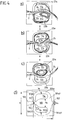
- a fluidic component 1 according to an embodiment of the invention is shown schematically.
- the Figures 2 and 3 show a sectional view of this fluidic component 1 along the lines A'-A "and B'-B".
- the fluidic component 1 comprises a flow chamber 10 through which a fluid flow 2 can flow ( Figure 4 ).
- the flow chamber 10 is also referred to as an interaction chamber.
- the flow chamber 10 comprises an inlet opening 101 via which the fluid flow 2 enters the flow chamber 10, and an outlet opening 102 via which the fluid flow 2 exits the flow chamber 10.
- the inlet opening 101 and the outlet opening 102 are arranged on two opposite sides of the fluidic component 1.
- the fluid flow 2 moves in the flow chamber 10 essentially along a longitudinal axis A of the fluidic component 1 (which connects the inlet opening 101 and the outlet opening 102 to one another) from the inlet opening 101 to the outlet opening 102.
- the longitudinal axis A forms an axis of symmetry of the fluidic component 1.
- the longitudinal axis A lies in two mutually perpendicular planes of symmetry S1 and S2, with respect to which the fluidic component 1 is mirror-symmetrical.
- the fluidic component 1 can not be constructed (mirror) symmetrically.
- the flow chamber 10 comprises a main flow channel 103, two secondary flow channels 104a, 104b, the main flow channel 103 (viewed transversely to the longitudinal axis A) being arranged between the two secondary flow channels 104a, 104b.
- the flow chamber 10 divides into the main flow channel 103 and the two secondary flow channels 104a, 104b, which are then brought together again immediately in front of the outlet opening 102.
- the two secondary flow channels 104a, 104b are arranged symmetrically with respect to the axis of symmetry S2 ( Figure 3 ). According to an alternative not shown, the secondary flow channels are not arranged symmetrically.
- the main flow channel 103 connects the inlet opening 101 and the outlet opening 102 with one another essentially in a straight line, so that the fluid flow 2 flows essentially along the longitudinal axis A of the fluidic component 1.
- the secondary flow channels 104a, 104b extend, starting from the inlet opening 101 in a first section, each initially at an angle of essentially 90 ° to the longitudinal axis A in opposite directions.
- the secondary flow ducts 104a, 104b then bend off so that they each extend essentially parallel to the longitudinal axis A (in the direction of the outlet opening 102) (second section).
- the secondary flow channels 104a, 104b change their direction again at the end of the second section so that they are each directed essentially in the direction of the longitudinal axis A (third section).
- the direction of the secondary flow channels 104a, 104b changes at the transition from the second to the third section by an angle of approximately 120 °.
- angles other than those mentioned here can also be selected.
- the secondary flow channels 104a, 104b are a means for influencing the direction of the fluid flow 2 which flows through the flow chamber 10.
- the bypass flow channels 104a, 104b each have an inlet 104a1, 104b1, which is essentially formed by the end of the bypass flow channels 104a, 104b facing the outlet opening 102, and each have an outlet 104a2, 104b2 which is essentially formed by the end of the bypass flow channels 104a, 104b2 facing the inlet opening 101 End of the bypass channels 104a, 104b is formed.
- a small part of the fluid flow 2 flows through the inlets 104a1, 104b1, the secondary flows 23a, 23b ( Figure 4 ), into the secondary flow channels 104a, 104b.
- the remaining part of the fluid flow 2 emerges from the fluidic component 1 via the outlet opening 102 ( Figure 4 ).
- the secondary flows 23a, 23b emerge from the secondary flow channels 104a, 104b at the outlets 104a2, 104b2, where they can exert a lateral (transverse to the longitudinal axis A) impulse on the fluid flow 2 entering through the inlet opening 101.
- the direction of the fluid flow 2 is influenced in such a way that the main flow 24 exiting at the outlet opening 102 oscillates spatially, specifically in a plane in which the main flow channel 103 and the secondary flow channels 104a, 104b are arranged.
- the plane in which the main flow 24 oscillates corresponds to the plane of symmetry S1 or is parallel to the plane of symmetry S1.
- Figure 4 which represents the oscillating fluid flow 2
- the secondary flow channels 104a, 104b each have a cross-sectional area which is almost constant over the entire length (from the inlet 104a1, 104b1 to the outlet 104a2, 104b2) of the secondary flow channels 104a, 104b.
- the size and / or shape of the cross-sectional area can change over the length of the secondary flow channels.
- the size of the cross-sectional area of the main flow channel 103 increases steadily in the flow direction of the main flow 23 (i.e. in the direction from the inlet opening 101 to the outlet opening 102), the shape of the main flow channel 103 being mirror-symmetrical to the planes of symmetry S1 and S2.
- the main flow channel 103 is separated from each secondary flow channel 104a, 104b by a block 11a, 11b.
- the two blocks 11a, 11b are in the embodiment from Figure 1 Identical in shape and size and arranged symmetrically with respect to the mirror plane S2. In principle, however, they can also be designed differently and not oriented symmetrically. If the alignment is not symmetrical, the shape of the main flow channel 103 is also not symmetrical with respect to the mirror plane S2.
- the shape of the brackets 11a, 11b shown in Figure 1 is shown is only exemplary and can be varied. Blocks 11a, 11b from Figure 1 have rounded edges.
- Separators 105a, 105b in the form of indentations are also provided at the inlet 104a1, 104b1 of the bypass flow channels 104a, 104b.
- an indentation 105a, 105b protrudes over a section of the peripheral edge of the secondary flow channel 104a, 104b into the respective secondary flow channel 104a, 104b and changes its cross-sectional shape at this point, reducing the cross-sectional area.
- each indentation 105a, 105b (among other things also) is directed towards the inlet opening 101 (oriented essentially parallel to the longitudinal axis A).
- the separators 105a, 105b can be oriented differently.
- the separation of the secondary streams 23a, 23b from the main stream 24 is influenced and controlled by the separators 105a, 105b.
- the shape, size and orientation of the separators 105a, 105b can influence the amount that flows from the fluid flow 2 into the secondary flow channels 104a, 104b, and the direction of the secondary flows 23a, 23b.
- the profile of the emerging at the outlet opening 102 can be targeted Main stream 24 are influenced.
- a separator can also be provided only at the inlet of one of the two bypass ducts.
- the separators 105a, 105b each have a shape which describes an arc in the plane of symmetry S1.
- this circular arc merges tangentially into the (linear) boundary wall of the outlet channel 107.
- this circular arc merges tangentially into a further circular arc 104a3, 104b3, which delimits the inlet 104a1, 104b1 of the secondary flow channel 104a, 104b.
- the circular arc of the separator 105a, 105b has a smaller radius than the circular arc 104a3, 104b3 of the inlet 104a1, 104b1 of the secondary flow channel 104a, 104b.
- the circular arc 104a3, 104b3 of the inlet 104a1, 104b1 of the secondary flow channel 104a, 104b also merges tangentially into the delimiting wall 104a4, 104b4 of the secondary flow channel 104a, 104b.
- the transition between the separators 105a, 105b and the secondary flow channels 104a, 104b on the one hand and the outlet channel 107 on the other hand is continuous, without jumps.
- the separators 105a, 105b are formed essentially opposite the end of the blocks 11a, 11b facing the outlet opening 102 in the boundary wall of the flow chamber 10.
- the separators 105a, 105b can be arranged at a distance from the plane of symmetry S2 which lies within the mean width of the blocks 11a, 11b.
- the mean width of a block 11a, 11b is the width which the block 11a, 11b (viewed in the direction of flow) has over half its length.
- the inlet opening 101 of the flow chamber 10 is preceded upstream by a funnel-shaped projection 106 which tapers in the direction of the inlet opening 101 (downstream).
- the length (along the direction of fluid flow) of the funnel-shaped extension 106 may be larger by a factor of at least 1.5 than the width b in the inlet port 101.
- the funnel-shaped extension 106 may be larger by a factor of at least 3 than the width b IN of the inlet opening 101.
- the flow chamber 10 also tapers, specifically in the area of the outlet opening 102.
- the tapering is formed by an outlet channel 107 which extends between the separators 105a, 105b and the outlet opening 102.
- the funnel-shaped extension 106 and the outlet channel 107 are tapered in such a way that only their width, that is to say their extension in the plane of symmetry S1 perpendicular to the longitudinal axis A, respectively decreases downstream.
- the taper does not affect the depth, that is, the expansion in the plane of symmetry S2 perpendicular to the longitudinal axis A, the extension 106 and the outlet channel 107 ( Figure 2 ).
- the extension 106 and the outlet channel 107 can each also be in taper in breadth and depth.
- only the extension 106 can taper in depth or in width, while the outlet channel 107 tapers in both width and depth, and vice versa.
- the extent of the tapering of the outlet channel 107 influences the directional characteristic of the fluid flow 2 emerging from the outlet opening 102 and thus its angle of oscillation.
- the shape of the funnel-shaped extension 106 and the outlet channel 107 are shown in FIG Figure 1 shown only as an example. Here, their width decreases linearly downstream. Other forms of taper are possible.
- the inlet opening 101 and the outlet opening 102 each have a rectangular cross-sectional area. These each have the same depth (extent in the plane of symmetry S2 perpendicular to the longitudinal axis A, Figure 2 ), but differ in their width b IN , b EX (extent in the plane of symmetry S1 perpendicular to the longitudinal axis A, Figure 1 ).
- the outlet opening 102 is less wide than the inlet opening 101.
- the cross-sectional area of the outlet opening 102 is smaller than the cross-sectional area of the inlet opening 101.
- the outlet opening 102 can be less deep than the inlet opening 101
- both the width and the depth of the outlet opening 102 can each be smaller than the width or the depth of the inlet opening 101.
- the dimensions of width and depth are to be selected so that the cross-sectional area of the outlet opening 102 is smaller than or the same size as the cross-sectional area of the inlet opening 101.
- the fluidic component 1 can have an outlet width b EX of 0.01 mm to 18 mm.
- the outlet width b EX is preferably between 0.1 mm and 8 mm.
- the ratio of the width b IN of the inlet opening 101 to the width b EX of the outlet opening 102 can be 1 to 6, preferably between 1 and 2.2.
- the dimensions of the component depth in the area of the inlet opening 101 and the outlet opening 102 are to be selected so that the cross-sectional area of the outlet opening 102 is smaller than or equal to the cross-sectional area of the inlet opening 101.
- the component width b can be at least a factor of 4 larger than the outlet width b EX .
- the component width b is preferably greater than the outlet width b EX by a factor of 6 to 21.
- the component length I can be at least a factor of 6 greater than the outlet width b EX .
- the component length I is preferably larger by a factor of 8 to 38 than the outlet width b EX .
- the widest part of the main flow channel (the greatest distance between the blocks 11a, 11b along the width of the fluidic component 1 considered) can be larger by a factor of 2 to 18 than the outlet width b EX . This factor is preferably between 3 and 12.
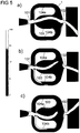
- FIG 4 three snapshots of a fluid flow 2 are shown to illustrate the flow direction (streamlines) of the fluid flow 2 in a fluidic component 1 during an oscillation cycle ( Figures a) to c)).
- the fluidic component 1 from Figure 4 differs from the fluidic component 1 from Figures 1 to 3 in particular in that no separators are provided and that the ends of the blocks 11 facing the inlet opening 101 are less rounded.
- the component length I of the fluidic component 1 from Figure 4 is 18 mm and the component width b is 20 mm ( Figure d)).
- the width b IN of the inlet opening 101 and the width b N of the secondary flow channels 104a, 104b are the same size and are each 2 mm.
- the outlet width b EX is 0.9 mm.
- the component depth is constant in this exemplary embodiment and is 0.9 mm.
- the main flow channel 103 has a maximum width b H between the blocks 11a, 11b of 8 mm.
- the fluid flowing through the fluidic component 1 has a pressure of 56 bar at the inlet opening 101, the fluid being water.
- the fluidic component 1 shown is basically also suitable for gaseous fluids.
- Figures a) and c) show the flow lines for two deflections of the exiting main flow 24, which approximately correspond to the maximum deflections.
- the angle that the exiting main stream 24 sweeps between these two maxima is the oscillation angle ⁇ ( Figure 7 ).
- Figure b) shows the flow lines for a position of the exiting main flow 24 which lies approximately in the middle between the two maxima from Figures a) and c). The flows within the fluidic component 1 during an oscillation cycle are described below.
- the fluid flow 2 is passed into the fluidic component 1 via the inlet opening 101 with an inlet pressure of 56 bar.
- the fluid flow 2 experiences hardly any pressure loss in the area of the inlet opening 101, since it can flow undisturbed into the main flow channel 103.
- the fluid flow 2 initially flows along the longitudinal axis A in the direction of the outlet opening 102.
- the fluid flow 2 is deflected laterally in the direction of the side wall of the one block 11a facing the main flow channel 103, so that the direction of the fluid flow 2 increasingly deviates from the longitudinal axis A until the fluid flow is maximally deflected.
- the major part of the fluid flow 2 the so-called main flow 24
- a recirculation area 25b is formed in the area between the main flow 24 and the other block 11b. The recirculation area 25b grows the more the main flow 24 is applied to the side wall of one block 11a.
- the main flow 24 emerges from the outlet opening 102 at an angle that changes over time with respect to the longitudinal axis A.
- the main flow 24 is on the side wall of the one block 11a and the recirculation area 25b has its maximum size.
- the main flow 24 emerges from the outlet opening 102 with approximately the greatest possible deflection.
- the main flow 24 is thus pressed against the side wall of the block 11a by the impulse (of the secondary flow 23b).
- the recirculation region 25b moves in the direction of the inlet 104b1 of the secondary flow channel 104b, as a result of which the supply of fluid into the secondary flow channel 104b is disturbed.
- the pulse component resulting from the bypass flow 23b thus decreases.
- the recirculation area 25b is reduced in size, while a further (growing) recirculation area 25a is formed between the main flow 24 and the side wall of the block 11a.
- the supply of fluid into the bypass duct 104a also increases.
- the pulse component resulting from the bypass flow 23a thus increases.
- the supply of fluid into the secondary flow channel 104a continues to increase, so that the pulse component resulting from the secondary flow 23a exceeds the pulse component resulting from the secondary flow 23b.
- the main flow 24 is thereby pushed further and further away from the side wall of the block 11a until it rests against the side wall of the opposite block 11b due to the Coanda effect ( Figure 4c )).
- the recirculation area 25b dissolves, while the recirculation area 25a grows to its maximum size.
- the main flow 24 now exits with maximum deflection, which is in comparison to the situation Figure 4a ) has an opposite sign, from the outlet opening 102.
- the recirculation area 25a will then migrate and block the inlet 104a1 of the secondary flow channel 104a, so that the supply of fluid here drops again.
- the secondary flow 23b will deliver the dominant pulse component, so that the main flow 24 is again pushed away from the side wall of the block 11b.
- the main flow 24 exiting at the outlet opening 102 oscillates about the longitudinal axis A in a plane in which the main flow channel 103 and the secondary flow channels 104a, 104b are arranged, so that a fluid jet wandering back and forth is generated.
- a symmetrical structure of the fluidic component 1 is not absolutely necessary.
- Figure 5 shows for each of the three snapshots a), b) and c) Figure 4 a corresponding transient flow simulation in order to visualize the velocity field of the fluid flow 2 inside and outside the fluidic component 1.
- Figure 5a of the snapshot Figure 4a ) etc.
- the in Figure 5 The scale shown translates the gray levels in which the fluid flow 2 is mapped into a velocity in m / s of the fluid flow.
- the speed is logarithmically coded with a color code. According to this, black corresponds to a fluid velocity of 0 m / s, while white corresponds to a fluid velocity of 150 m / s. The lighter the fluid is displayed at one point, the higher its speed at that point.
- Figures a) to c) show that the main flow 24 at the outlet opening 102 with a Exits speed which is always higher than the speed at which the fluid flow 2 enters at the inlet opening 101. This is due to the fact that the outlet opening 102 has a smaller cross-sectional area than the inlet opening 101.
- the speed of the exiting main stream 24 is around 150 m / s.
- a fluid jet is thus generated at high speed or high momentum. Despite the high speed of the exiting fluid jet, the oscillation mechanism is retained.
- Figure 6 shows off for the snapshot Figure 4b ) ( Figure 5b )) the corresponding pressure field of the fluid flow 2.
- the pressure is logarithmically coded with a color code. The scale shown ranges from 1 bar (white) to 60 bar (black). Upstream of the inlet opening 101, the pressure of the fluid is 56 bar. The ambient pressure is 1 bar (white).
- Figure 6 clearly shows that the pressure of the fluid in the entire fluidic component 1 is high and essentially corresponds to the pressure before entry into the fluidic component 1 through the inlet opening 101. Only at the outlet opening 102 does the pressure of the fluid drop abruptly to the ambient pressure. In connection with Figure 5b ) it can be seen that the fluid is accelerated at this point of the pressure drop.
- the Figures 7a ) to c) show three individual recordings of a fluid jet emerging from a fluidic component 1 to illustrate the spray characteristics.
- the fluidic component 1 has a component length I of 22 mm, a component width of 23 mm and a component depth of 3 mm.
- the inlet opening 101 has a width b IN of 3 mm, and the outlet opening 102 has a width b EX of 2.5 mm.
- Separators 105a, 105b are provided at the inlets of the bypass ducts 104a, 104b.
- the secondary flow channels 104a, 104b each have a constant width b N of 4 mm.
- the main flow channel 103 is 9 mm wide at its widest point (b H ).
- the fluidic component 1 is flowed through with water as a fluid, wherein in Figure 7a ) the pressure of the water at the inlet port 101 0.5 bar, in Figure 7b ) 2.5 bar and in Figure 7c ) Is 7 bar. As the pressure of the water at the inlet opening 101 rises, the oscillation frequency f of the exiting fluid jet increases, the oscillation angle ⁇ essentially remaining the same.
- FIG. 8 and 9 cross-sections of two further embodiments of the fluidic component 1 are shown.
- the sectional view of the Figures 8 and 9 corresponds to that of Figure 3 .
- the Figures 8 and 9 thus each show a section through the fluidic component 1 transversely to the longitudinal axis A and thus a section through the main flow duct 103 and the secondary flow ducts 104a, 104b transversely to the flow direction.
- the fluidic components from the Figures 8 and 9 correspond to the fluidic component 1 from characters 1 to 3 and differ from the latter only in the cross-sectional shapes of the main flow channel 103 and the secondary flow channels 104a, 104b.
- the Figures 10 and 11 show two further embodiments of the fluidic component 1. These two embodiments differ from that one Figure 1 in particular in that a flow divider 108 is provided in the outlet channel 107, but no separator at the inlets 104a1, 104b1 of the bypass channels 104a, 104b.
- the shape of the blocks 11a, 11b is also different. The fundamental geometric properties of these two embodiments, however, agree with those of the fluidic component 1 Figure 1 match.
- the flow divider 108 each has the shape of a triangular wedge.
- the wedge has a depth which corresponds to the component depth t. (The component depth t is constant over the entire fluidic component 1.)
- the flow divider 108 thus divides the outlet channel 107 into two sub-channels with two outlet openings 102 and the fluid flow 2 into two sub-flows that exit from the fluidic component 1.
- the oscillation mechanism described above the two substrate streams emerge from the two outlet openings 102 in a pulsed manner.
- the two outlet openings 102 each have a smaller width b EX than the inlet opening 101.
- the flow divider 108 extends essentially in the outlet channel 107, while in the embodiment it extends Figure 11 extends into the main flow channel 103.
- the shape and size of the flow divider 108 can in principle be freely selected depending on the desired application.
- a plurality of flow dividers can also be provided (next to one another along the width of the component) in order to subdivide the exiting fluid jet into more than two sub-flows.
- the Figures 10 and 11 also show two further embodiments for the blocks 11a, 11b. However, these shapes are only to be provided by way of example and not exclusively in connection with the flow divider 108. Likewise, the blocks 11a, 11b can be designed differently when using a flow divider 108.
- the blocks out Figure 10 have an essentially trapezoidal basic shape which tapers downstream (in width) and from the ends of which a triangular projection protrudes into the main flow channel 103. Blocks 11a, 11b from Figure 11 resemble those from Figure 1 , but do not have rounded corners.
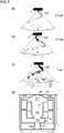
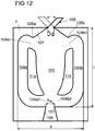
- Figure 12 shows the fluidic component 1 from Figure 1 , which additionally has a fluid flow guide 109.
- the fluid flow guide 109 is a tubular extension which is arranged at the outlet opening 102 and extends downstream from the outlet opening 102.
- the fluid flow guide 109 serves to bundle the exiting fluid flow without affecting the oscillation mechanism.
- the fluid flow guide 109 is movably arranged on the outlet opening 102 and is moved along by the movement of the exiting fluid flow. This is in Figure 12 illustrated by the double arrow.
- one of the two maximum deflections of the fluid flow guide 109 is shown as a continuous line and the other of the two maximum deflections of the fluid flow guide 109 is shown as a dotted line.
- FIG. 11 shows a further embodiment for the fluidic component 1 with the fluid flow guide 109 Figure 12 shown.
- the fluidic component 1 additionally has a flow guide body 110, which is connected to the fluid flow guide 109 by means of a holder 111.
- the flow guide body 110 serves to support the deflection of the fluid flow emerging from the outlet opening 102 and thus also the movement of the fluid flow guide 109 utilizing the fluid dynamics in the flow chamber 10.
- the holder 111 is designed in such a way that it does not interfere with the oscillation mechanism of the emerging fluid flow. In particular, the holder has a small cross section and thus a negligible flow resistance.
- the holder 111 produces a rigid connection between the flow guide body 110 and the fluid flow guide 109.
- the flow guide body 110 is therefore not movable with respect to the fluid flow guide 109, but rather only together with the fluid flow guide 109.
- the shape of the flow guide body 110 can be designed differently. In particular, the flow guide body 110 can be streamlined. In the Figure 13 The rectangular shape of the flow guide body 110 shown is only a schematic illustration.
- Flow guide body 110 described is not based on that in Figure 13
- the fluidic component 1 shown is limited, but can also be used in other fluidic components 1 with a fluid flow guide 109.
- the fluid flow guide 109 can also be used in other fluidic components besides those from the Figures 12 and 13 can be used.
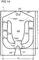
- Figure 14 shows a fluidic component 1, which is essentially the fluidic component 1 from Figure 1 corresponds.
- the fluidic component 1 from Figure 14 differs from that Figure 1 in that the cross-sectional area of the secondary flow channels 104a, 104b is not constant over their length.
- the component depth of the fluidic component 1 from Figure 14 is constant over the entire fluidic component 1.
- the cross-sectional area of the secondary flow channels 104a, 104b is accordingly achieved by changing their width.
- the secondary flow channel 104a thus has a greater width at its inlet 104a1 and at its outlet 104a2 than in a section between inlet 104a1 and outlet 104a2.
- the widths b Na1 , b Na2 , b Na3 of the secondary flow channel 104a shown are b Na1 > b Na2 and b Na3 > b Na2 .
- b Na3 > b Na1 , but b Na3 b Na1 or b Na3 ⁇ b Na1 can also apply.
- the secondary flow channel 104b has a greater width at its inlet 104b1 than at its outlet 104b2.
- the widths b Nb1 , b Nb2 of the secondary flow channel 104b shown are b Nb1 > b Nb2 .
- the entrance width can be smaller than the exit width.
- the width of the bypass channels 104a, 104b changes differently over their length. This is achieved in that the two blocks 11a, 11b are designed differently in shape and size and are not aligned symmetrically with respect to the mirror plane S2. As a result, the shape of the main flow channel 103 is also not symmetrical to the mirror plane S2. However, both secondary flow channels 104a, 104b can behave the same with regard to their change in width.
- the manufacturing process (casting, sintering) of the fluidic component 1 can be simplified, since foreign substances can easily be removed from the fluidic component during manufacture.
- the finished fluidic component can be cleaned more easily, which plays a role, for example, when the fluidic component is used with a foreign substance-laden (particle-laden) fluid.
- the variant in which If the cross-section from the outlet of the bypass duct to the inlet of the bypass duct increases, the fluidic component flushes itself free during operation.
- the fluid runs completely out of the fluidic component when the fluidic component is switched off (i.e. when no more fluid is passed into the fluidic component). It can thus be avoided that fluid collects in the fluidic component after switching off and that pathogens (for example Legionella) in the fluid multiply or mold, soap residues, lime or other dirt build up.
- pathogens for example Legionella
- An emptying of the fluidic component after switching off can be supported by dispensing with separators.
- variable width of the secondary flow channels 104a, 104b described is not limited to the in Figure 14 shown fluidic component 1 limited. Rather, the variable width of the secondary flow channels / of the secondary flow channel can also be applied to other forms of fluidic components with one or more secondary flow channels.
- a fluidic component 1 which has a cavity 112 downstream of the outlet opening 102. Otherwise it corresponds to the fluidic component Figure 4d ).
- the cavity 112 is an annular widening of the outlet channel 107 adjoining the outlet opening 102, which (viewed in the flow direction of the exiting fluid flow) extends over a section of the outlet channel 107.
- An annular widening is to be understood as a widening that has a round, angular, oval or otherwise shaped, closed contour.
- the cavity is arranged directly at the outlet opening 102. However, it can also be arranged further downstream.
- the cavity 112 reduces the boundary layer height of the fluid flow emerging from the outlet opening 102.
- the cavity 112 can be provided for the most varied of embodiments of a fluidic component 1 and is not aimed at the fluidic component 1 Figure 15 limited.
- FIG 16 a fluidic component 1 according to a further embodiment of the invention is shown schematically.
- the Figures 17 and 18 show a sectional view of this fluidic component 1 along the lines A'-A "and B'-B".
- the fluidic component 1 from the Figures 16 to 18 corresponds essentially to the fluidic component from the Figures 1 to 3 .
- the fluidic component 1 from the Figures 16 to 18 differs from the fluidic component from the Figures 1 to 3 in particular that an outlet widening 12 is provided.
- the outlet widening 12 adjoins the outlet opening 102 downstream.
- the fluid flow 2 thus moves from the outlet opening 102 through the outlet widening 12 before the fluid flow 2 emerges from the fluidic component 1.
- the pressure within the fluidic component 1 can increase and thus reduce the inclination of the cavity.
- the inlet pressure which is, for example, higher than 14 bar (compared to the ambient pressure), but can also be above 1000 bar, and is preferably between 20 bar and 500 bar, is essentially only reduced at the outlet opening 102. Due to the high pressure reduction directly at the outlet opening 102, the exiting fluid jet can tend to burst (in all directions). This bursting can be counteracted (at least partially) by the outlet widening 12.
- the exiting fluid jet can be bundled (perpendicular to the planes of symmetry S1 and S2). By bundling the fluid jet in this way, an increase in the removal or cleaning performance of the fluidic component 1 can be achieved.
- the outlet widening 12 is funnel-shaped and has a cross-sectional area which, starting from the outlet opening 102, increases in the fluid flow direction (from the inlet opening 101 to the outlet opening 102).
- the depth of the outlet expansion 12 is constant, while the width of the outlet expansion 12 increases in the direction of the fluid flow. According to Figure 16 the width increases linearly. However, a steady increase other than the linear increase in width is also possible.
- the outlet opening 102 forms the point with the smallest cross-sectional area between the flow chamber 10 and the outlet expansion 12.
- the walls delimiting the outlet expansion 12 enclose an angle ⁇ in the plane in which the exiting fluid jet oscillates.
- the angle ⁇ corresponds in the embodiment from Figure 16 the oscillation angle ⁇ of the exiting fluid jet, which would be formed without the outlet widening 12.
- the angle ⁇ can also be greater than the corresponding oscillation angle ⁇ be formed.
- a fluidic component 1 that generates a uniform distribution of the fluid on the surface to be sprayed (also known as a histogram) without an outlet expansion 12
- a fluidic component 1 without an outlet widening 12 generates an uneven distribution of the fluid on the surface to be sprayed (for example more fluid in the center than in the edge areas) or in the event that a smaller spray angle or oscillation angle ⁇ is desired
- An outlet widening 12 can be provided, the angle ⁇ of which corresponds to the desired reduced oscillation angle ⁇ . In this way, on the one hand, a smaller oscillation angle ⁇ is generated and, on the other hand, a more uniform distribution of the fluid on the surface to be sprayed or in the histogram is generated.
- the walls delimiting the outlet channel 107 enclose an angle ⁇ in the plane in which the exiting fluid jet oscillates.
- the angle ⁇ of the outlet channel 107 can be larger than the oscillation angle ⁇ and also larger than the angle ⁇ of the outlet widening 12.
- the angle ⁇ of the outlet channel 107 is preferably at least 1.1 times greater than the angle ⁇ of the outlet widening 12. According to a particularly preferred embodiment, 1.1 * ⁇ ⁇ 3.5 * ⁇ applies.
- the outlet widening 12 has a length I out which adjoins the component length I.
- the length I out of the outlet expansion 12 can correspond at least to the width b EX of the outlet opening 102.
- the length I out of the outlet widening 12 can preferably be greater than the width b EX of the outlet opening 102 by at least a factor of 1.25.
- the length I out of the outlet extension 12 can preferably be a factor of 1 to 32 greater than the outlet width b EX , particularly preferably a factor of 4 to 16. With this ratio, a fluid jet with high jet quality can be generated.
- the separators 105a, 105b are formed by an indentation in the wall of the secondary flow channels 104a, 104b.
- the indentation has a shape that describes an arc in the plane of symmetry S1.
- the radius of the circular arc can be of different strengths.
- the radius of the circular arc can be 0.0075 to 2.6 times, preferably 0.015 to 1.8 times, and particularly preferably 0.055 to 1.7 times the outlet width b EX .
- the component depth t is constant over the entire outlet widening 12 and corresponds to the component depth at the outlet opening 102 exists.
- the depth t of the outlet widening 12 can increase or decrease downstream (compared to the component depth that is present at the outlet opening 102).
- a further focusing of the exiting fluid jet can be achieved by reducing the component depth in the area of the outlet widening 12 in a downstream direction.
- a fluidic component 1 according to a further embodiment of the invention is shown schematically.
- This fluidic component like the fluidic component 1 from FIG Figure 16 an outlet expansion 12.
- the shapes of the secondary flow channels 104a, 104b, the blocks 11a, 11b and the separators 105a, 105b are similar to the shapes of the fluidic component 1 Figure 7d ).
- the basic shape of the fluidic component 1 from Figure 19 is essentially rectangular.
- the blocks 11a and 11b have an essentially rectangular basic shape, at whose end facing the inlet opening 101 a triangular projection adjoins, which protrudes into the main flow channel.
- the blocks 11a and 11b can be sharp-edged or slightly rounded at the meeting points of the straight sections, as in FIG Figure 19 shown.
- the secondary flow channels 104a, 104b extend, starting from the inlet opening 101 in a first section, each initially at an angle of essentially 90 ° to the longitudinal axis A in opposite directions. Subsequently, the secondary flow channels 104a, 104b bend (essentially at right angles) so that they each extend essentially parallel to the longitudinal axis A (in the direction of the outlet opening 102) (second section). The second section is followed by a third section. The change in direction during the transition from the second to the third section is essentially 90 °.
- the separators 105a, 105b are made of Figure 16 not formed by an indentation in the wall of the bypass ducts 104a, 104b, but rather by the transition of the straight third section of the bypass ducts 104a, 104b (which extends essentially perpendicular to the longitudinal axis A and the plane of symmetry S2) into the wall of the outlet duct 107, which forms an angle smaller than 90 ° with the longitudinal axis A (and the plane of symmetry S2).
- the separators 105a, 105b are accordingly formed by an edge.
- the separators 105a, 105b (as in the embodiment from FIGS Figures 16 to 18 ) have a shape that describes an arc in the plane of symmetry S1.
- the third section of the secondary flow channels 104a, 104b extends essentially perpendicular to the plane of symmetry S2, but the angle can also deviate from 90 °.
- the separators 105a, 105b can preferably be arranged at a distance from the plane of symmetry S2 which lies within the mean width of the blocks 11a, 11b.
- FIG Figures 16 to 19 The shape of the fluidic components 1 with an outlet expansion 12 is shown in FIG Figures 16 to 19 shown only as an example.
- the outlet widening 12 can also be provided in connection with other embodiments of the fluidic component 1 according to the invention.
Landscapes
- Engineering & Computer Science (AREA)
- Chemical & Material Sciences (AREA)
- Mechanical Engineering (AREA)
- General Engineering & Computer Science (AREA)
- Combustion & Propulsion (AREA)
- Analytical Chemistry (AREA)
- Physics & Mathematics (AREA)
- Fluid Mechanics (AREA)
- Nozzles (AREA)
- Measuring Volume Flow (AREA)
- Physical Or Chemical Processes And Apparatus (AREA)
- Jet Pumps And Other Pumps (AREA)
Priority Applications (1)
| Application Number | Priority Date | Filing Date | Title |
|---|---|---|---|
| PL16798135T PL3317546T3 (pl) | 2015-11-18 | 2016-11-16 | Komponent fluidalny |
Applications Claiming Priority (3)
| Application Number | Priority Date | Filing Date | Title |
|---|---|---|---|
| DE102015222771.5A DE102015222771B3 (de) | 2015-11-18 | 2015-11-18 | Fluidisches Bauteil |
| DE202016104170.8U DE202016104170U1 (de) | 2015-11-18 | 2016-07-29 | Fluidisches Bauteil |
| PCT/EP2016/077864 WO2017085129A1 (de) | 2015-11-18 | 2016-11-16 | Fluidisches bauteil |
Publications (2)
| Publication Number | Publication Date |
|---|---|
| EP3317546A1 EP3317546A1 (de) | 2018-05-09 |
| EP3317546B1 true EP3317546B1 (de) | 2020-09-09 |
Family
ID=58281595
Family Applications (1)
| Application Number | Title | Priority Date | Filing Date |
|---|---|---|---|
| EP16798135.6A Active EP3317546B1 (de) | 2015-11-18 | 2016-11-16 | Fluidisches bauteil |
Country Status (8)
| Country | Link |
|---|---|
| US (3) | US20180318848A1 (pl) |
| EP (1) | EP3317546B1 (pl) |
| CN (2) | CN108431430B (pl) |
| DE (2) | DE102015222771B3 (pl) |
| DK (1) | DK3317546T3 (pl) |
| ES (1) | ES2827310T3 (pl) |
| PL (1) | PL3317546T3 (pl) |
| WO (1) | WO2017085129A1 (pl) |
Families Citing this family (14)
| Publication number | Priority date | Publication date | Assignee | Title |
|---|---|---|---|---|
| DE202015104279U1 (de) | 2015-06-08 | 2016-12-21 | Technische Universität Berlin | Fluidisches Bauteil und Anwendungen des fluidischen Bauteils |
| DE102015222771B3 (de) * | 2015-11-18 | 2017-05-18 | Technische Universität Berlin | Fluidisches Bauteil |
| US11305297B2 (en) * | 2017-06-05 | 2022-04-19 | Dlhbowles, Inc. | Compact low flow rate fluidic nozzle for spraying and cleaning applications having a reverse mushroom insert geometry |
| DE102017212747B3 (de) * | 2017-07-25 | 2018-11-08 | Fdx Fluid Dynamix Gmbh | Fluidisches Bauteil, fluidische Baugruppe und Fluidverteilungsgerät |
| DE102017212961A1 (de) * | 2017-07-27 | 2019-01-31 | Fdx Fluid Dynamix Gmbh | Fluidisches Bauteil |
| US10144394B1 (en) * | 2017-11-08 | 2018-12-04 | Uber Technologies, Inc. | Nozzles and systems for cleaning vehicle sensors |
| JP7426102B2 (ja) * | 2018-02-20 | 2024-02-01 | スプレイング システムズ カンパニー | 分割本体流体噴霧ノズル |
| CN108731037A (zh) * | 2018-04-04 | 2018-11-02 | 美的集团股份有限公司 | 微波炉 |
| GB201905126D0 (en) * | 2019-04-11 | 2019-05-29 | Perlemax Ltd | Fluidic oscilators |
| US11073071B2 (en) * | 2019-07-23 | 2021-07-27 | Ford Global Technologies, Llc | Fuel injector with divided flowpath nozzle |
| US10753154B1 (en) | 2019-10-17 | 2020-08-25 | Tempress Technologies, Inc. | Extended reach fluidic oscillator |
| CN111271346B (zh) * | 2020-01-23 | 2021-04-30 | 上海交通大学 | 一种子母流体振荡器 |
| LU102636B1 (en) * | 2021-03-04 | 2022-09-05 | Stratec Se | Sensor for determining the oscillating frequency in a fluidic oscillating nozzle and a method using the sensor |
| CN113280366B (zh) * | 2021-05-13 | 2022-09-27 | 中国航空发动机研究院 | 一种基于自激扫掠振荡燃油喷嘴的加力燃烧室结构 |
Family Cites Families (95)
| Publication number | Priority date | Publication date | Assignee | Title |
|---|---|---|---|---|
| US3016066A (en) | 1960-01-22 | 1962-01-09 | Raymond W Warren | Fluid oscillator |
| US3185166A (en) | 1960-04-08 | 1965-05-25 | Billy M Horton | Fluid oscillator |
| US3563462A (en) | 1968-11-21 | 1971-02-16 | Bowles Eng Corp | Oscillator and shower head for use therewith |
| GB1297154A (pl) | 1969-10-29 | 1972-11-22 | ||
| US3748852A (en) | 1969-12-05 | 1973-07-31 | L Cole | Self-stabilizing pressure compensated injector |
| GB1453587A (en) | 1973-04-05 | 1976-10-27 | Atomic Energy Authority Uk | Flowmeters |
| US4407032A (en) | 1973-05-02 | 1983-10-04 | Bowles Fluidics Corporation | Washing method using a fluidic oscillator |
| DE2505695A1 (de) | 1974-09-30 | 1976-04-22 | Bowles Fluidics Corp | Vorrichtung zum verspruehen eines fluids, insbesondere fluidischer oszillator |
| US3973558A (en) | 1974-09-30 | 1976-08-10 | Bowles Fluidics Corporation | Swept jet oral irrigator |
| US4052002A (en) * | 1974-09-30 | 1977-10-04 | Bowles Fluidics Corporation | Controlled fluid dispersal techniques |
| DE2736314C3 (de) | 1977-08-12 | 1980-07-31 | Alfred Kaercher Gmbh & Co, 7057 Winnenden | Düse zum Versprühen eines unter Druck stehenden Mediums |
| US4151955A (en) * | 1977-10-25 | 1979-05-01 | Bowles Fluidics Corporation | Oscillating spray device |
| US4244230A (en) | 1978-10-12 | 1981-01-13 | Peter Bauer | Fluidic oscillator flowmeter |
| DE2757522C2 (de) | 1977-12-23 | 1979-11-22 | Behr, Hans, 7000 Stuttgart | Rund- oder Ringstrahldüse zum Erzeugen und Abstrahlen eines Nebels oder Aerosols zur Beschichtung von Gegenständen |
| US4463904A (en) * | 1978-11-08 | 1984-08-07 | Bowles Fluidics Corporation | Cold weather fluidic fan spray devices and method |
| US4645126A (en) * | 1978-11-08 | 1987-02-24 | Bowles Fluidics Corporation | Cold weather fluidic windshield washer method |
| DE2906648C3 (de) | 1979-02-21 | 1981-09-10 | Alfred Kärcher GmbH & Co, 7057 Winnenden | Spritzdüsenanordnung für Hochdruckreinigungsgeräte |
| US4508267A (en) * | 1980-01-14 | 1985-04-02 | Bowles Fluidics Corporation | Liquid oscillator device |
| EP0044331B1 (en) | 1980-01-14 | 1986-01-02 | Bowles Fluidics Corporation | Liquid oscillator device |
| DE3400934A1 (de) * | 1983-03-31 | 1984-12-06 | Knorr-Bremse Fluidics GmbH, 8000 München | Koerperpflege- und koerperreinigungsgeraet, insbesondere zahn- und gesichtsreinigungsbuerste oder munddusche und fluidischer oszillator, insbesondere zur verwendung in solchen geraeten |
| IT1196066B (it) | 1983-03-31 | 1988-11-10 | Knorr Bremse Fluidics Gmbh | Dispositivi di spruzzatura,in particolare apparecchio per la pulizia del corpo e/o apparecchiatura di massaggio eseguito a guisa di spazzolino,in particolare spazzolino da denti |
| US4721251A (en) | 1984-07-27 | 1988-01-26 | Nippon Soken, Inc. | Fluid dispersal device |
| JPH038458A (ja) * | 1989-06-06 | 1991-01-16 | Matsushita Electric Works Ltd | 流体発振素子 |
| DE4303762A1 (de) | 1993-02-09 | 1994-08-11 | Kaercher Gmbh & Co Alfred | Flachstrahldüse für ein Hochdruckreinigungsgerät |
| FR2707705B1 (fr) * | 1993-07-13 | 1995-09-15 | Schlumberger Ind Sa | Oscillateur fluidique à large gamme de débits et compteur de fluide comportant un tel oscillateur. |
| IT1268535B1 (it) | 1993-12-20 | 1997-03-04 | Zanussi Elettrodomestici | Programma operativo per macchina lavastoviglie |
| IT1267638B1 (it) | 1994-12-02 | 1997-02-07 | Elbi Int Spa | Macchina lavastoviglie. |
| CN1179199A (zh) * | 1995-02-06 | 1998-04-15 | 施蓝姆伯格工业公司 | 流体流调节方法及流体流调节器 |
| US5524660A (en) * | 1995-06-28 | 1996-06-11 | Basf Corporation | Plate-type spray nozzle and method of use |
| US5749525A (en) * | 1996-04-19 | 1998-05-12 | Bowles Fluidics Corporation | Fluidic washer systems for vehicles |
| DE19646972A1 (de) * | 1996-11-14 | 1998-05-20 | Mannesmann Vdo Ag | Ausschließlich durch Ansprühen mit Waschflüssigkeit arbeitende Scheibenreinigungsanlage |
| US5845845A (en) * | 1997-02-19 | 1998-12-08 | Bowles Fluidics Corporation | Fluidic circuit with attached cover and method |
| US5820034A (en) * | 1997-04-23 | 1998-10-13 | Bowles Fluidics Corporation | Cylindrical fluidic circuit |
| US6110292A (en) | 1997-08-12 | 2000-08-29 | Warren R. Jewett | Oscillating liquid jet washing system |
| US5906317A (en) * | 1997-11-25 | 1999-05-25 | Bowles Fluidics Corporation | Method and apparatus for improving improved fluidic oscillator and method for windshield washers |
| DE19854127B4 (de) | 1998-11-24 | 2005-10-06 | Siemens Ag | Reinigungsanlage für eine Scheibe eines Kraftfahrzeuges |
| US6186409B1 (en) | 1998-12-10 | 2001-02-13 | Bowles Fluidics Corporation | Nozzles with integrated or built-in filters and method |
| IT1311214B1 (it) | 1999-03-29 | 2002-03-04 | Electrolux Zanussi Elettrodome | Lavastoviglie con getti d'acqua pulsanti |
| DE19943262A1 (de) * | 1999-09-10 | 2001-03-15 | Mannesmann Vdo Ag | Fluidicdüse |
| DE29918178U1 (de) | 1999-10-14 | 1999-12-16 | Lechler GmbH + Co. KG, 72555 Metzingen | Vorrichtung zur Reinigung von Oberflächen |
| US7293722B1 (en) * | 1999-10-14 | 2007-11-13 | Bowles Fluidics Corporation | Method and apparatus for generation of low impact sprays |
| NL1015139C2 (nl) | 2000-05-09 | 2003-08-13 | Waterkracht Bv | Werkwijze en inrichting voor reiniging met water. |
| DE20019430U1 (de) | 2000-11-15 | 2001-07-19 | FMS Maschinen Service GmbH, 33378 Rheda-Wiedenbrück | Rotordüse für ein Hochdruckreinigungsgerät |
| US6948244B1 (en) * | 2001-03-06 | 2005-09-27 | Bowles Fluidics Corporation | Method of molding fluidic oscillator devices |
| DE60117382T2 (de) * | 2001-07-02 | 2006-10-19 | Hitachi Ltd. | Verbrennungsmotor mit direkter einspritzung in den zylinder |
| DE10144574A1 (de) | 2001-09-11 | 2003-03-27 | Voith Paper Patent Gmbh | Verfahren und Vorrichtung zum Reinigen eines Transportbands einer Maschine zur Herstellung einer Materialbahn |
| GB2385095B (en) * | 2002-01-23 | 2005-11-09 | Alstom | Fluidic apparatuses |
| US7014131B2 (en) | 2002-06-20 | 2006-03-21 | Bowles Fluidics Corporation | Multiple spray devices for automotive and other applications |
| CZ12485U1 (cs) | 2002-06-25 | 2002-07-24 | Hydrosystem Group, A.S. | Fluidická tryska |
| WO2004018109A1 (ja) * | 2002-08-22 | 2004-03-04 | Asmo Co., Ltd. | ウォッシャノズル及びウォッシャ装置 |
| US7302731B2 (en) * | 2002-12-11 | 2007-12-04 | Asmo Co., Ltd. | Washer equipment |
| JP4178064B2 (ja) * | 2003-03-19 | 2008-11-12 | 株式会社日立産機システム | 純流体素子 |
| EP1472966A2 (en) * | 2003-05-01 | 2004-11-03 | Epenhuysen Chemie N.V. | Machine dish-washing process |
| US20040250837A1 (en) | 2003-06-13 | 2004-12-16 | Michael Watson | Ware wash machine with fluidic oscillator nozzles |
| JP2005059651A (ja) * | 2003-08-08 | 2005-03-10 | Asmo Co Ltd | 車両用ウォッシャノズル及び車両用ウォッシャ装置 |
| CN2653112Y (zh) * | 2003-08-14 | 2004-11-03 | 中国石化集团胜利石油管理局钻井工艺研究院 | 一种钻头水力脉动喷嘴 |
| DE10339505A1 (de) | 2003-08-27 | 2005-03-24 | Siemens Ag | Zur Befestigung in einem Kraftfahrzeug vorgesehene Einrichtung zur Reinigung einer Scheibe oder einer Streuscheibe |
| US20070295840A1 (en) * | 2003-09-29 | 2007-12-27 | Bowles Fluidics Corporation | Fluidic oscillators and enclosures with split throats |
| US7651036B2 (en) * | 2003-10-28 | 2010-01-26 | Bowles Fluidics Corporation | Three jet island fluidic oscillator |
| US20050252539A1 (en) * | 2004-05-17 | 2005-11-17 | Asmo Co., Ltd. | Vehicular washer nozzle |
| JP2006001529A (ja) * | 2004-05-17 | 2006-01-05 | Asmo Co Ltd | 車両用ウォッシャノズル及び車両用ウォッシャ装置 |
| US7354008B2 (en) * | 2004-09-24 | 2008-04-08 | Bowles Fluidics Corporation | Fluidic nozzle for trigger spray applications |
| EP1827703B1 (en) | 2004-11-01 | 2012-08-01 | Bowles Fluidics Corporation | Improved cold-performance fluidic oscillator |
| US7267290B2 (en) * | 2004-11-01 | 2007-09-11 | Bowles Fluidics Corporation | Cold-performance fluidic oscillator |
| US8662421B2 (en) * | 2005-04-07 | 2014-03-04 | Bowles Fluidics Corporation | Adjustable fluidic sprayer |
| DE102006012080A1 (de) | 2006-03-14 | 2007-09-27 | Miele & Cie. Kg | Spülmaschine |
| ATE398962T1 (de) | 2005-06-08 | 2008-07-15 | Miele & Cie | Spülmaschine |
| US7128082B1 (en) * | 2005-08-10 | 2006-10-31 | General Electric Company | Method and system for flow control with fluidic oscillators |
| JP4658771B2 (ja) * | 2005-10-24 | 2011-03-23 | アスモ株式会社 | 車両用ウォッシャノズル及び車両用ウォッシャ装置 |
| WO2007139891A1 (en) * | 2006-05-24 | 2007-12-06 | Bowles Fluidics Corporation | Fluidic oscillator |
| US20110061692A1 (en) | 2006-12-14 | 2011-03-17 | Shridhar Gopalan | Full coverage fluidic oscillator with automated cleaning system and method |
| DE102007012878B3 (de) | 2007-03-17 | 2008-10-30 | Apson Lackiertechnik Gmbh | Zerstäuber zum Zerstäuben eines Beschichtungsmittels |
| EP2222408B1 (en) * | 2007-12-07 | 2018-02-14 | dlhBowles Inc. | Irrigation nozzle assembly |
| US7951244B2 (en) | 2008-01-11 | 2011-05-31 | Illinois Tool Works Inc. | Liquid cleaning apparatus for cleaning printed circuit boards |
| JP5349820B2 (ja) * | 2008-03-25 | 2013-11-20 | 株式会社ミツバ | ノズルおよびその製造方法、ならびにウォッシャノズル |
| US8702020B2 (en) | 2008-05-16 | 2014-04-22 | Bowles Fluidics Corporation | Nozzle and fluidic circuit adapted for use with cold fluids, viscous fluids or fluids under light pressure |
| US8091434B2 (en) | 2008-06-10 | 2012-01-10 | Avinash Shrikrishna Vaidya | Fluidic oscillator flow meter |
| US20100123031A1 (en) * | 2008-11-17 | 2010-05-20 | Caterpillar Inc. | Fluid oscillator assembly for fuel injectors and fuel injection system using same |
| DE202009003800U1 (de) | 2009-03-18 | 2009-06-04 | Fraport Ag Frankfurt Airport Services Worldwide | Kehrgerät für eine Oberfläche |
| DE102009059038A1 (de) | 2009-12-11 | 2011-06-16 | Lechler Gmbh | Tankreinigungsdüse |
| CN102059178B (zh) * | 2010-12-02 | 2012-07-04 | 厦门松霖科技有限公司 | 一种出脉动喷溅水的机构 |
| US20120144832A1 (en) | 2010-12-10 | 2012-06-14 | General Electric Company | Passive air-fuel mixing prechamber |
| US8418725B2 (en) * | 2010-12-31 | 2013-04-16 | Halliburton Energy Services, Inc. | Fluidic oscillators for use with a subterranean well |
| US8733401B2 (en) | 2010-12-31 | 2014-05-27 | Halliburton Energy Services, Inc. | Cone and plate fluidic oscillator inserts for use with a subterranean well |
| DE202011109850U1 (de) | 2011-04-06 | 2012-08-08 | Lechler Gmbh | Rotierende Düsenanordnung |
| DE102011078587A1 (de) | 2011-07-04 | 2013-01-10 | Schaeffler Technologies AG & Co. KG | Vormontierter Zugmitteltrieb |
| CN202410860U (zh) * | 2012-01-05 | 2012-09-05 | 何念民 | 射流超低频喷射器 |
| DE102012200289A1 (de) | 2012-01-11 | 2013-07-11 | BSH Bosch und Siemens Hausgeräte GmbH | Haushalts-Dampfgargerät mit außerhalb des Behandlungsraums angeordnetem Dampferzeuger |
| EP2650213B1 (en) | 2012-04-12 | 2014-07-16 | Airbus Operations GmbH | Flow body having a leading edge, a surface and an active flow control system and vehicle comprising at least one such flow body and an air source |
| DE102012217263B4 (de) | 2012-09-25 | 2023-02-02 | Deutsches Zentrum für Luft- und Raumfahrt e.V. | Drallbrenner und Verfahren zum Betrieb eines Drallbrenners |
| JP5491612B1 (ja) | 2012-12-11 | 2014-05-14 | 三菱電機株式会社 | 流体噴射弁及び噴霧生成装置 |
| US9339825B2 (en) * | 2013-03-06 | 2016-05-17 | The United States Of America As Represented By The Administrator Of The National Aeronautics And Space Administration | Fluidic oscillator having decoupled frequency and amplitude control |
| US9333517B2 (en) * | 2013-03-06 | 2016-05-10 | The United States Of America As Represented By The Administrator Of The National Aeronautics And Space Administration | Fluidic oscillator array for synchronized oscillating jet generation |
| WO2016010971A1 (en) * | 2014-07-15 | 2016-01-21 | Bowles Fluidics Corporation | Improved three-jet island fluidic oscillator circuit, method and nozzle assembly |
| DE102015222771B3 (de) * | 2015-11-18 | 2017-05-18 | Technische Universität Berlin | Fluidisches Bauteil |
-
2015
- 2015-11-18 DE DE102015222771.5A patent/DE102015222771B3/de not_active Expired - Fee Related
-
2016
- 2016-07-29 DE DE202016104170.8U patent/DE202016104170U1/de not_active Expired - Lifetime
- 2016-11-16 US US15/773,344 patent/US20180318848A1/en not_active Abandoned
- 2016-11-16 DK DK16798135.6T patent/DK3317546T3/da active
- 2016-11-16 ES ES16798135T patent/ES2827310T3/es active Active
- 2016-11-16 WO PCT/EP2016/077864 patent/WO2017085129A1/de not_active Ceased
- 2016-11-16 CN CN201680067815.9A patent/CN108431430B/zh active Active
- 2016-11-16 PL PL16798135T patent/PL3317546T3/pl unknown
- 2016-11-16 EP EP16798135.6A patent/EP3317546B1/de active Active
- 2016-11-16 CN CN202211167430.3A patent/CN115445804A/zh active Pending
-
2020
- 2020-03-27 US US16/832,861 patent/US11471898B2/en active Active
-
2021
- 2021-10-27 US US17/511,708 patent/US20220055044A1/en not_active Abandoned
Non-Patent Citations (1)
| Title |
|---|
| None * |
Also Published As
| Publication number | Publication date |
|---|---|
| PL3317546T3 (pl) | 2021-03-08 |
| US20180318848A1 (en) | 2018-11-08 |
| DE102015222771B3 (de) | 2017-05-18 |
| DK3317546T3 (da) | 2020-12-07 |
| CA3033710A1 (en) | 2017-05-26 |
| CN108431430A (zh) | 2018-08-21 |
| US20220055044A1 (en) | 2022-02-24 |
| CN115445804A (zh) | 2022-12-09 |
| EP3317546A1 (de) | 2018-05-09 |
| CN108431430B (zh) | 2023-03-14 |
| ES2827310T3 (es) | 2021-05-20 |
| WO2017085129A1 (de) | 2017-05-26 |
| US11471898B2 (en) | 2022-10-18 |
| US20200238304A1 (en) | 2020-07-30 |
| DE202016104170U1 (de) | 2017-02-22 |
Similar Documents
| Publication | Publication Date | Title |
|---|---|---|
| EP3317546B1 (de) | Fluidisches bauteil | |
| DE102017212747B3 (de) | Fluidisches Bauteil, fluidische Baugruppe und Fluidverteilungsgerät | |
| EP3615223A1 (de) | Fluidische baugruppe | |
| DE69912398T2 (de) | Düsen mit integrierten oder eingebauten filtern und deren herstellungsverfahren | |
| EP2931434B1 (de) | Flachstrahldüse | |
| DE102016208344A1 (de) | Fluidisches Bauteil | |
| DE60204806T2 (de) | Strahlvorrichtung für einen Gemengestrom von Gas und Flüssigkeit | |
| EP2129903A1 (de) | Kraftstoffinjektor mit einer zusätzlichen ablaufdrossel oder mit einer verbesserten anordnung derselben im steuerventil | |
| WO2018065533A1 (de) | Fluidisches bauteil | |
| DE102012013328A1 (de) | Vorrichtung zur Erzeugung von Fluidpulsen | |
| DE102012014965A1 (de) | Düsenanordnung | |
| EP3935230B1 (de) | Strahlregler | |
| DE602004010697T2 (de) | Fluidoszillator mit drei krafteinlassdüsen und einem wirbel erzeugenden hindernis | |
| DE202011100748U1 (de) | Breitschlitzdüse zum Austragen von fließfähigem Material | |
| EP3088087B1 (de) | Sprühdüse und verfahren zum erzeugen von nicht runden sprühkegeln | |
| EP0646679B1 (de) | Filtersieb für Wasserauslaufarmaturen | |
| DE102022204734B4 (de) | Hydraulischer Schalter und Bohrhammer | |
| EP2051816B1 (de) | Flexible düse zum austrag einer flüssigkeit und geräte mit einer solchen düse | |
| EP4197643A1 (de) | Düse mit einstellbarer strahlgeometrie, düsenanordnung und verfahren zum betrieb einer düse | |
| WO2014037092A1 (de) | Wasserauslaufarmatur mit verbessertem strömungsverhalten | |
| DE2065063A1 (de) | Fluidik-Oszillator. Ausscheidung aus: 2017600 | |
| DE102016015907B3 (de) | Fluidisches Bauteil | |
| DE102024115642A1 (de) | Fluidverteilungsvorrichtung | |
| DE1750284A1 (de) | Logisches Druckmittelelement | |
| EP4508355A1 (de) | Dämpfungsvorrichtung |
Legal Events
| Date | Code | Title | Description |
|---|---|---|---|
| STAA | Information on the status of an ep patent application or granted ep patent |
Free format text: STATUS: UNKNOWN |
|
| STAA | Information on the status of an ep patent application or granted ep patent |
Free format text: STATUS: THE INTERNATIONAL PUBLICATION HAS BEEN MADE |
|
| PUAI | Public reference made under article 153(3) epc to a published international application that has entered the european phase |
Free format text: ORIGINAL CODE: 0009012 |
|
| STAA | Information on the status of an ep patent application or granted ep patent |
Free format text: STATUS: REQUEST FOR EXAMINATION WAS MADE |
|
| 17P | Request for examination filed |
Effective date: 20180130 |
|
| AK | Designated contracting states |
Kind code of ref document: A1 Designated state(s): AL AT BE BG CH CY CZ DE DK EE ES FI FR GB GR HR HU IE IS IT LI LT LU LV MC MK MT NL NO PL PT RO RS SE SI SK SM TR |
|
| AX | Request for extension of the european patent |
Extension state: BA ME |
|
| DAV | Request for validation of the european patent (deleted) | ||
| DAX | Request for extension of the european patent (deleted) | ||
| STAA | Information on the status of an ep patent application or granted ep patent |
Free format text: STATUS: EXAMINATION IS IN PROGRESS |
|
| 17Q | First examination report despatched |
Effective date: 20190506 |
|
| RIC1 | Information provided on ipc code assigned before grant |
Ipc: F02M 61/18 20060101ALI20200311BHEP Ipc: F15C 1/22 20060101AFI20200311BHEP Ipc: F15B 21/12 20060101ALI20200311BHEP Ipc: B05B 1/08 20060101ALI20200311BHEP |
|
| GRAP | Despatch of communication of intention to grant a patent |
Free format text: ORIGINAL CODE: EPIDOSNIGR1 |
|
| STAA | Information on the status of an ep patent application or granted ep patent |
Free format text: STATUS: GRANT OF PATENT IS INTENDED |
|
| INTG | Intention to grant announced |
Effective date: 20200420 |
|
| GRAS | Grant fee paid |
Free format text: ORIGINAL CODE: EPIDOSNIGR3 |
|
| GRAA | (expected) grant |
Free format text: ORIGINAL CODE: 0009210 |
|
| STAA | Information on the status of an ep patent application or granted ep patent |
Free format text: STATUS: THE PATENT HAS BEEN GRANTED |
|
| AK | Designated contracting states |
Kind code of ref document: B1 Designated state(s): AL AT BE BG CH CY CZ DE DK EE ES FI FR GB GR HR HU IE IS IT LI LT LU LV MC MK MT NL NO PL PT RO RS SE SI SK SM TR |
|
| RAP1 | Party data changed (applicant data changed or rights of an application transferred) |
Owner name: FDX FLUID DYNAMIX GMBH |
|
| REG | Reference to a national code |
Ref country code: GB Ref legal event code: FG4D Free format text: NOT ENGLISH |
|
| REG | Reference to a national code |
Ref country code: AT Ref legal event code: REF Ref document number: 1311935 Country of ref document: AT Kind code of ref document: T Effective date: 20200915 Ref country code: CH Ref legal event code: EP |
|
| REG | Reference to a national code |
Ref country code: DE Ref legal event code: R096 Ref document number: 502016011145 Country of ref document: DE |
|
| REG | Reference to a national code |
Ref country code: IE Ref legal event code: FG4D Free format text: LANGUAGE OF EP DOCUMENT: GERMAN |
|
| REG | Reference to a national code |
Ref country code: NL Ref legal event code: FP |
|
| REG | Reference to a national code |
Ref country code: SE Ref legal event code: TRGR |
|
| REG | Reference to a national code |
Ref country code: DK Ref legal event code: T3 Effective date: 20201203 |
|
| REG | Reference to a national code |
Ref country code: LT Ref legal event code: MG4D |
|
| PG25 | Lapsed in a contracting state [announced via postgrant information from national office to epo] |
Ref country code: HR Free format text: LAPSE BECAUSE OF FAILURE TO SUBMIT A TRANSLATION OF THE DESCRIPTION OR TO PAY THE FEE WITHIN THE PRESCRIBED TIME-LIMIT Effective date: 20200909 Ref country code: LT Free format text: LAPSE BECAUSE OF FAILURE TO SUBMIT A TRANSLATION OF THE DESCRIPTION OR TO PAY THE FEE WITHIN THE PRESCRIBED TIME-LIMIT Effective date: 20200909 Ref country code: BG Free format text: LAPSE BECAUSE OF FAILURE TO SUBMIT A TRANSLATION OF THE DESCRIPTION OR TO PAY THE FEE WITHIN THE PRESCRIBED TIME-LIMIT Effective date: 20201209 Ref country code: FI Free format text: LAPSE BECAUSE OF FAILURE TO SUBMIT A TRANSLATION OF THE DESCRIPTION OR TO PAY THE FEE WITHIN THE PRESCRIBED TIME-LIMIT Effective date: 20200909 Ref country code: NO Free format text: LAPSE BECAUSE OF FAILURE TO SUBMIT A TRANSLATION OF THE DESCRIPTION OR TO PAY THE FEE WITHIN THE PRESCRIBED TIME-LIMIT Effective date: 20201209 Ref country code: GR Free format text: LAPSE BECAUSE OF FAILURE TO SUBMIT A TRANSLATION OF THE DESCRIPTION OR TO PAY THE FEE WITHIN THE PRESCRIBED TIME-LIMIT Effective date: 20201210 |
|
| PG25 | Lapsed in a contracting state [announced via postgrant information from national office to epo] |
Ref country code: LV Free format text: LAPSE BECAUSE OF FAILURE TO SUBMIT A TRANSLATION OF THE DESCRIPTION OR TO PAY THE FEE WITHIN THE PRESCRIBED TIME-LIMIT Effective date: 20200909 Ref country code: RS Free format text: LAPSE BECAUSE OF FAILURE TO SUBMIT A TRANSLATION OF THE DESCRIPTION OR TO PAY THE FEE WITHIN THE PRESCRIBED TIME-LIMIT Effective date: 20200909 |
|
| PG25 | Lapsed in a contracting state [announced via postgrant information from national office to epo] |
Ref country code: RO Free format text: LAPSE BECAUSE OF FAILURE TO SUBMIT A TRANSLATION OF THE DESCRIPTION OR TO PAY THE FEE WITHIN THE PRESCRIBED TIME-LIMIT Effective date: 20200909 Ref country code: PT Free format text: LAPSE BECAUSE OF FAILURE TO SUBMIT A TRANSLATION OF THE DESCRIPTION OR TO PAY THE FEE WITHIN THE PRESCRIBED TIME-LIMIT Effective date: 20210111 Ref country code: CZ Free format text: LAPSE BECAUSE OF FAILURE TO SUBMIT A TRANSLATION OF THE DESCRIPTION OR TO PAY THE FEE WITHIN THE PRESCRIBED TIME-LIMIT Effective date: 20200909 Ref country code: SM Free format text: LAPSE BECAUSE OF FAILURE TO SUBMIT A TRANSLATION OF THE DESCRIPTION OR TO PAY THE FEE WITHIN THE PRESCRIBED TIME-LIMIT Effective date: 20200909 Ref country code: EE Free format text: LAPSE BECAUSE OF FAILURE TO SUBMIT A TRANSLATION OF THE DESCRIPTION OR TO PAY THE FEE WITHIN THE PRESCRIBED TIME-LIMIT Effective date: 20200909 |
|
| REG | Reference to a national code |
Ref country code: ES Ref legal event code: FG2A Ref document number: 2827310 Country of ref document: ES Kind code of ref document: T3 Effective date: 20210520 |
|
| PG25 | Lapsed in a contracting state [announced via postgrant information from national office to epo] |
Ref country code: AL Free format text: LAPSE BECAUSE OF FAILURE TO SUBMIT A TRANSLATION OF THE DESCRIPTION OR TO PAY THE FEE WITHIN THE PRESCRIBED TIME-LIMIT Effective date: 20200909 Ref country code: IS Free format text: LAPSE BECAUSE OF FAILURE TO SUBMIT A TRANSLATION OF THE DESCRIPTION OR TO PAY THE FEE WITHIN THE PRESCRIBED TIME-LIMIT Effective date: 20210109 |
|
| REG | Reference to a national code |
Ref country code: DE Ref legal event code: R097 Ref document number: 502016011145 Country of ref document: DE |
|
| PG25 | Lapsed in a contracting state [announced via postgrant information from national office to epo] |
Ref country code: MC Free format text: LAPSE BECAUSE OF FAILURE TO SUBMIT A TRANSLATION OF THE DESCRIPTION OR TO PAY THE FEE WITHIN THE PRESCRIBED TIME-LIMIT Effective date: 20200909 Ref country code: SK Free format text: LAPSE BECAUSE OF FAILURE TO SUBMIT A TRANSLATION OF THE DESCRIPTION OR TO PAY THE FEE WITHIN THE PRESCRIBED TIME-LIMIT Effective date: 20200909 |
|
| REG | Reference to a national code |
Ref country code: CH Ref legal event code: PL |
|
| PLBE | No opposition filed within time limit |
Free format text: ORIGINAL CODE: 0009261 |
|
| STAA | Information on the status of an ep patent application or granted ep patent |
Free format text: STATUS: NO OPPOSITION FILED WITHIN TIME LIMIT |
|
| PG25 | Lapsed in a contracting state [announced via postgrant information from national office to epo] |
Ref country code: LU Free format text: LAPSE BECAUSE OF NON-PAYMENT OF DUE FEES Effective date: 20201116 |
|
| REG | Reference to a national code |
Ref country code: BE Ref legal event code: MM Effective date: 20201130 |
|
| 26N | No opposition filed |
Effective date: 20210610 |
|
| PG25 | Lapsed in a contracting state [announced via postgrant information from national office to epo] |
Ref country code: CH Free format text: LAPSE BECAUSE OF NON-PAYMENT OF DUE FEES Effective date: 20201130 Ref country code: LI Free format text: LAPSE BECAUSE OF NON-PAYMENT OF DUE FEES Effective date: 20201130 Ref country code: SI Free format text: LAPSE BECAUSE OF FAILURE TO SUBMIT A TRANSLATION OF THE DESCRIPTION OR TO PAY THE FEE WITHIN THE PRESCRIBED TIME-LIMIT Effective date: 20200909 |
|
| PG25 | Lapsed in a contracting state [announced via postgrant information from national office to epo] |
Ref country code: MT Free format text: LAPSE BECAUSE OF FAILURE TO SUBMIT A TRANSLATION OF THE DESCRIPTION OR TO PAY THE FEE WITHIN THE PRESCRIBED TIME-LIMIT Effective date: 20200909 Ref country code: CY Free format text: LAPSE BECAUSE OF FAILURE TO SUBMIT A TRANSLATION OF THE DESCRIPTION OR TO PAY THE FEE WITHIN THE PRESCRIBED TIME-LIMIT Effective date: 20200909 |
|
| PG25 | Lapsed in a contracting state [announced via postgrant information from national office to epo] |
Ref country code: MK Free format text: LAPSE BECAUSE OF FAILURE TO SUBMIT A TRANSLATION OF THE DESCRIPTION OR TO PAY THE FEE WITHIN THE PRESCRIBED TIME-LIMIT Effective date: 20200909 |
|
| PG25 | Lapsed in a contracting state [announced via postgrant information from national office to epo] |
Ref country code: BE Free format text: LAPSE BECAUSE OF NON-PAYMENT OF DUE FEES Effective date: 20201130 |
|
| P01 | Opt-out of the competence of the unified patent court (upc) registered |
Effective date: 20230530 |
|
| PGFP | Annual fee paid to national office [announced via postgrant information from national office to epo] |
Ref country code: NL Payment date: 20251119 Year of fee payment: 10 |
|
| PGFP | Annual fee paid to national office [announced via postgrant information from national office to epo] |
Ref country code: DE Payment date: 20251118 Year of fee payment: 10 |
|
| PGFP | Annual fee paid to national office [announced via postgrant information from national office to epo] |
Ref country code: GB Payment date: 20251120 Year of fee payment: 10 |
|
| PGFP | Annual fee paid to national office [announced via postgrant information from national office to epo] |
Ref country code: AT Payment date: 20251117 Year of fee payment: 10 |
|
| PGFP | Annual fee paid to national office [announced via postgrant information from national office to epo] |
Ref country code: IT Payment date: 20251128 Year of fee payment: 10 Ref country code: DK Payment date: 20251119 Year of fee payment: 10 |
|
| PGFP | Annual fee paid to national office [announced via postgrant information from national office to epo] |
Ref country code: FR Payment date: 20251120 Year of fee payment: 10 |
|
| PGFP | Annual fee paid to national office [announced via postgrant information from national office to epo] |
Ref country code: TR Payment date: 20251111 Year of fee payment: 10 |
|
| PGFP | Annual fee paid to national office [announced via postgrant information from national office to epo] |
Ref country code: SE Payment date: 20251119 Year of fee payment: 10 |
|
| PGFP | Annual fee paid to national office [announced via postgrant information from national office to epo] |
Ref country code: IE Payment date: 20251120 Year of fee payment: 10 |
|
| PGFP | Annual fee paid to national office [announced via postgrant information from national office to epo] |
Ref country code: PL Payment date: 20251110 Year of fee payment: 10 |
|
| PGFP | Annual fee paid to national office [announced via postgrant information from national office to epo] |
Ref country code: ES Payment date: 20251216 Year of fee payment: 10 |