EP3317601B1 - Verfahren und anlage zum aufbereiten und trocknen von festen kleinstückigen materialien - Google Patents
Verfahren und anlage zum aufbereiten und trocknen von festen kleinstückigen materialien Download PDFInfo
- Publication number
- EP3317601B1 EP3317601B1 EP15753322.5A EP15753322A EP3317601B1 EP 3317601 B1 EP3317601 B1 EP 3317601B1 EP 15753322 A EP15753322 A EP 15753322A EP 3317601 B1 EP3317601 B1 EP 3317601B1
- Authority
- EP
- European Patent Office
- Prior art keywords
- drying
- gas
- unit
- drying step
- dried
- Prior art date
- Legal status (The legal status is an assumption and is not a legal conclusion. Google has not performed a legal analysis and makes no representation as to the accuracy of the status listed.)
- Active
Links
Images


Classifications
-
- F—MECHANICAL ENGINEERING; LIGHTING; HEATING; WEAPONS; BLASTING
- F26—DRYING
- F26B—DRYING SOLID MATERIALS OR OBJECTS BY REMOVING LIQUID THEREFROM
- F26B3/00—Drying solid materials or objects by processes involving the application of heat
- F26B3/02—Drying solid materials or objects by processes involving the application of heat by convection, i.e. heat being conveyed from a heat source to the materials or objects to be dried by a gas or vapour, e.g. air
- F26B3/14—Drying solid materials or objects by processes involving the application of heat by convection, i.e. heat being conveyed from a heat source to the materials or objects to be dried by a gas or vapour, e.g. air the materials or objects to be dried being moved by gravity
- F26B3/16—Drying solid materials or objects by processes involving the application of heat by convection, i.e. heat being conveyed from a heat source to the materials or objects to be dried by a gas or vapour, e.g. air the materials or objects to be dried being moved by gravity in a counter-flow of the gas or vapour
-
- F—MECHANICAL ENGINEERING; LIGHTING; HEATING; WEAPONS; BLASTING
- F26—DRYING
- F26B—DRYING SOLID MATERIALS OR OBJECTS BY REMOVING LIQUID THEREFROM
- F26B17/00—Machines or apparatus for drying materials in loose, plastic, or fluidised form, e.g. granules, staple fibres, with progressive movement
- F26B17/12—Machines or apparatus for drying materials in loose, plastic, or fluidised form, e.g. granules, staple fibres, with progressive movement with movement performed solely by gravity, i.e. the material moving through a substantially vertical drying enclosure, e.g. shaft
- F26B17/122—Machines or apparatus for drying materials in loose, plastic, or fluidised form, e.g. granules, staple fibres, with progressive movement with movement performed solely by gravity, i.e. the material moving through a substantially vertical drying enclosure, e.g. shaft the material moving through a cross-flow of drying gas; the drying enclosure, e.g. shaft, consisting of substantially vertical, perforated walls
-
- F—MECHANICAL ENGINEERING; LIGHTING; HEATING; WEAPONS; BLASTING
- F26—DRYING
- F26B—DRYING SOLID MATERIALS OR OBJECTS BY REMOVING LIQUID THEREFROM
- F26B21/00—Arrangements for supplying or controlling air or other gases for drying solid materials or objects
- F26B21/20—Circulating air or gases in closed cycles, e.g. wholly within the drying enclosure
- F26B21/25—Circulating air or gases in closed cycles, e.g. wholly within the drying enclosure partly outside the drying enclosure
-
- F—MECHANICAL ENGINEERING; LIGHTING; HEATING; WEAPONS; BLASTING
- F26—DRYING
- F26B—DRYING SOLID MATERIALS OR OBJECTS BY REMOVING LIQUID THEREFROM
- F26B3/00—Drying solid materials or objects by processes involving the application of heat
- F26B3/02—Drying solid materials or objects by processes involving the application of heat by convection, i.e. heat being conveyed from a heat source to the materials or objects to be dried by a gas or vapour, e.g. air
- F26B3/14—Drying solid materials or objects by processes involving the application of heat by convection, i.e. heat being conveyed from a heat source to the materials or objects to be dried by a gas or vapour, e.g. air the materials or objects to be dried being moved by gravity
-
- F—MECHANICAL ENGINEERING; LIGHTING; HEATING; WEAPONS; BLASTING
- F26—DRYING
- F26B—DRYING SOLID MATERIALS OR OBJECTS BY REMOVING LIQUID THEREFROM
- F26B2200/00—Drying processes and machines for solid materials characterised by the specific requirements of the drying goods
- F26B2200/24—Wood particles, e.g. shavings, cuttings, saw dust
-
- Y—GENERAL TAGGING OF NEW TECHNOLOGICAL DEVELOPMENTS; GENERAL TAGGING OF CROSS-SECTIONAL TECHNOLOGIES SPANNING OVER SEVERAL SECTIONS OF THE IPC; TECHNICAL SUBJECTS COVERED BY FORMER USPC CROSS-REFERENCE ART COLLECTIONS [XRACs] AND DIGESTS
- Y02—TECHNOLOGIES OR APPLICATIONS FOR MITIGATION OR ADAPTATION AGAINST CLIMATE CHANGE
- Y02E—REDUCTION OF GREENHOUSE GAS [GHG] EMISSIONS, RELATED TO ENERGY GENERATION, TRANSMISSION OR DISTRIBUTION
- Y02E50/00—Technologies for the production of fuel of non-fossil origin
- Y02E50/10—Biofuels, e.g. bio-diesel
-
- Y—GENERAL TAGGING OF NEW TECHNOLOGICAL DEVELOPMENTS; GENERAL TAGGING OF CROSS-SECTIONAL TECHNOLOGIES SPANNING OVER SEVERAL SECTIONS OF THE IPC; TECHNICAL SUBJECTS COVERED BY FORMER USPC CROSS-REFERENCE ART COLLECTIONS [XRACs] AND DIGESTS
- Y02—TECHNOLOGIES OR APPLICATIONS FOR MITIGATION OR ADAPTATION AGAINST CLIMATE CHANGE
- Y02E—REDUCTION OF GREENHOUSE GAS [GHG] EMISSIONS, RELATED TO ENERGY GENERATION, TRANSMISSION OR DISTRIBUTION
- Y02E50/00—Technologies for the production of fuel of non-fossil origin
- Y02E50/30—Fuel from waste, e.g. synthetic alcohol or diesel
Definitions
- the invention relates to a method and a system for drying wood chips, wood shavings or other solid, small-sized materials of organic and/or mineral origin.
- the materials consist of a large number of solid particles and are pourable. They are also referred to as bulk material or heap material.
- the method and the system according to the invention are particularly suitable for use in a method and a system for producing wood pellets or other solid granules from small-sized material of organic and/or mineral origin.
- Wood pellets are rod-shaped granules made from sawdust or shavings, wood chips, shredded wood or other by-products or waste from the wood and frost industries.
- Other solid granules made from small pieces of material of organic and/or mineral origin can be made from straw, sunflower shells, olive stones, olive press residue, rice husks, meat or fish waste and other biogenic residues from the agricultural, meat, fish or food industries, with the addition of mineral components in different combinations and proportions.
- the material supplied is processed for pelletizing, in particular by drying, and if necessary also by crushing and conditioning. The pellets are pressed from the processed material.
- a pan mill press for example, in which the material is pressed through a die with holes according to the desired pellet diameter.
- the lignin contained in the material is released by the heating during conditioning or pressing and binds the individual wood particles together. It is also known to add binding agents to the material to be granulated in order to bind the particles together. After they leave the die, a knife cuts the pellet strands to the desired length. The pellets are then cooled and solidified.
- the EN 10 2013 224 204 A1 describes a plant for producing wood pellets or other solid granules that can be transported, set up and moved to another location with little effort and enables energy-optimized operation.
- the plant is at least partially arranged in containers that can be transported individually and assembled in a modular manner to form at least a significant part of the plant, with at least the cooling device in the form of a shaft cooler being arranged entirely in a container.
- At least one of the devices for feeding, processing, drying, pressing, cooling and dispensing is arranged in a container with a vertical longitudinal axis.
- the dryer is a belt dryer and a storage silo for intermediate storage is arranged downstream of the dryer. The material is transported from the storage silo to the drying mill, where it is crushed to the optimal grain size.
- Drying in drum dryers is also well known. These work with a burner that heats the heating gas to a very high temperature of, for example, 400°C. The waste heat still has a high temperature of, for example, 90°C and is not used.
- VOC volatile organic compounds
- lignin are dissolved out of wood particles. This reduces the quality of the material. The lignin is missing as a binding agent during pelletization.
- the EN 10 2006 061 340 B3 describes a device for producing wood pellets with at least one assembly module for feeding, drying, pressing and discharging.
- the assembly modules are placed in a vertical arrangement of the respective functional assemblies in containers that are commercially available worldwide (12-20 foot containers).
- Several containers forming a horizontal and/or vertical row are connected to one another by means of electrical and/or pneumatic media lines and one of the containers can be connected to a local media source.
- the easy and quick assembly of the system, which consists of prepared assembly modules, is advantageous.
- the system includes a dryer with vertical drying shafts for wood chips that extend over two containers placed horizontally on top of each other. Wood chips enter the drying shaft at the top and exit again at the bottom. Fans and heat exchangers arranged on different sides of the drying shaft ensure that the wood chips are dehumidified.
- the upper fan sucks air heated by the upper heat exchanger through the drying shaft and the lower fan sucks air heated by the lower heat exchanger in the opposite direction through the drying shaft. This is intended to achieve a high throughput.
- the drying air sucked through the drying shaft is released into the environment. There is little flexibility in terms of adapting the dryer to different throughputs.
- the EP 2 719 983 A1 describes a drying plant for bulk material, in particular agricultural grains, which comprises several drying zones through which the bulk material to be dried passes one after the other.
- An air duct directs air through the drying zones.
- a first air inlet directs Fresh air from the environment as supply air into a first part of the drying zones.
- the first air inlet is designed as a supply air shaft.
- An air forwarder is provided for forwarding exhaust air from the first part of the drying zones into a second part of the drying zones.
- a second air inlet directs further fresh air from the environment into the second part of the drying zones.
- the second air inlet can be equipped with a throttle or control flap to influence the additional fresh air supplied.
- Fresh air is supplied to the drying zones by means of a third air inlet.
- the third air inlet is an air duct device such as a pipe or a duct.
- the invention is based on the object of creating a method and a system for drying wood chips, wood shavings or other solid, small-sized materials of organic and/or mineral origin with improved energy efficiency and increased flexibility.
- the second drying gas is also used in the first drying step after cooling in the second drying step and/or the thermal energy bound in the material is used for drying in the first drying step.
- the drying gas is preferably air or a mixture of combustion gas and air.
- the dried material from the second drying step is dried using the second preheated drying gas and the second preheated drying gas, which has been cooled to a temperature above the ambient air temperature in the third drying step, is fed to the second drying step.
- the energy of the second preheated drying gas is used for the third drying step and the second drying step and the energy efficiency is further improved.
- the dried material from the second The drying step is only cooled by means of the cooling gas after the third drying step has been completed.
- the invention further includes embodiments in which the material undergoes more than three drying steps.
- the second preheated drying gas is preferably used first for the last drying step and, after cooling to a temperature above ambient temperature, for at least one preceding drying step.
- the dried material from the first or second drying step undergoes a rest period in which the water content within the particles of the material is more or less evened out, and the material is dried in the second or third drying step after the rest period.
- the rest period which is preferably half to two hours, more preferably one to one and a half hours, the water content of the cross-section of the particles is more or less evened out, so that water migrates from the core to the surface of the particles. This improves the efficiency of the subsequent drying step.
- the dried material from the first drying step or from the second drying step is crushed and then fed to the second drying step or the third drying step.
- the moisture inside the particles is exposed on the surface so that the subsequent drying can be carried out more efficiently.
- the dried material is crushed between two drying steps and undergoes a rest period.
- the crushing and the rest period can take place in any sequence.
- the particles are first crushed and then undergo a rest period.
- the dried material is crushed between the same drying steps and undergoes a rest period.
- the invention further includes embodiments in which the crushing takes place between two drying steps other than the rest period.
- the cooled and moistened drying gas from the first drying step and/or from the second drying step is released into the environment.
- largely cooled drying gas is released into the environment.
- the cooled and moistened drying gas from the second drying step is dried and the dried drying gas is mixed with the ambient air and fed as a second drying gas to the second or third drying step.
- the remaining thermal energy of the drying gas from the second drying step is used to heat the ambient air.
- the condensed water resulting from drying the drying gas from the second drying step is fed to a heat pump and the heat supplied by the heat pump at an increased temperature level is used to heat the ambient air. This also recovers the energy bound in the water in the drying air for the process and further improves energy efficiency.
- a portion of the cooled, second drying gas from the third drying step is mixed with the heated cooling gas and fed to the first drying step as the first drying gas. This further improves the utilization of the thermal energy of the second drying gas.
- the ambient air and/or the dried drying gas is heated by means of a heat exchanger and/or by means of a heating burner.
- the heat exchanger is operated using the energy supplied by the heat pump and/or with the waste heat from a production process and/or with the heat from a combined heat and power plant.
- wood dust or wood pellets from the process or another fossil fuel can be used.
- the use of a heating burner has the advantage that the drying gas has a high proportion of heating gases, which reduces the risk of ignition of flammable or easily combustible material as a result of the greatly reduced oxygen content of the heating gases.
- the first and/or the second and/or the third drying step takes place in such a way that the material passes through a vertical drying section from top to bottom and the drying gas is passed through the drying section in cross-countercurrent, the drying section being divided into individual sections in which the mass flow of the drying gas, which is passed across a section of the drying section, can be adjusted.
- This allows larger or smaller flow rates of the drying gas to be passed through the drying section in the various sections of the drying section.
- This enables adaptation to the material used in each case.
- With a coarser material e.g. wood chips
- multiple deflection of the drying gas with relatively high speeds of the drying gas when passing through the drying section is advantageous because this results in drying and coarse material is less easily discharged from the side of the drying section.
- finer material e.g. chips
- less frequent deflection and thus a lower flow velocity of the drying gas when passing through the drying shaft can be advantageous.
- the ambient air is heated by being sucked by a fan in a substantially horizontal direction through a box-shaped, vertical arrangement of four heat exchangers and heated as it passes through the heat exchangers and then sucked in in a vertical direction by the fan arranged below the heat exchangers and fed by them to the second or third drying step.
- the plant is a preferred form of implementation of the process mentioned above and has its energetic advantages.
- the system comprises a rest container which is designed such that in the rest container the dried material from the first drying step or from the second drying step undergoes a rest period in which the water content within the particles of the material becomes more or less uniform, wherein the material is made available for further drying in the second drying step or in the third drying step after the rest period has passed. This further improves the efficiency of the drying.
- the system comprises a comminution device which is designed to comminute the dried material from the first drying unit or from the second drying unit and to provide it for drying in the second drying unit or in the third drying unit. This further improves the efficiency of the drying.
- the drying system comprises both a rest container and a shredding device, whereby the order is basically arbitrary, but preferably the material passes through the shredding device before the rest container.
- the shredding device can be arranged between two drying units other than the rest container.
- the first drying unit and/or the second drying unit comprises an outlet to the environment for discharging cooled and humidified drying gas. Due to the low temperature of the drying gas in the first drying unit and/or the second drying unit, it only has a low energy and can be discharged into the environment.
- the system comprises a gas drying unit which is designed to dry the cooled and humidified drying gas from the second drying unit and to provide it to the gas preparation unit for mixing with the ambient air.
- a gas drying unit which is designed to dry the cooled and humidified drying gas from the second drying unit and to provide it to the gas preparation unit for mixing with the ambient air.
- the system comprises a heat pump which is designed to raise the heat of the water condensed in the gas drying unit to an increased temperature level and to supply it to the gas preparation unit for to heat the ambient air. This further increases the energy efficiency of the system.
- the third drying unit is connected via a line to the line between the cooling unit and the first drying unit in order to mix cooled, second drying air from the third drying unit with the heated air from the cooling unit and to supply it as first drying air to the first drying unit.
- the gas preparation unit for generating a heated drying gas has a cuboid-shaped housing with heat exchangers arranged in four vertical side walls at a distance from the lower end, each of which is gas-permeable in the horizontal direction, a fan arranged below the heat exchangers in the housing with an air inlet on the top and an air outlet which is connected to a drying unit via a line.
- the gas preparation unit enables the transfer of high heat outputs with little space requirement.
- each heat exchanger of the gas preparation unit comprises a register and a tube bundle on the inside of the register. This is advantageous for energetically favorable preheating and postheating of the drying gas sucked in.
- the tube bundle is preferably also a component of all heat exchangers.
- a drying unit comprises at least one vertical drying shaft and vertical gas shafts on both sides of the drying shaft, the shaft walls between the drying shaft and the gas shafts being perforated, the drying shaft has an inlet at the top for material to be dried and an outlet at the bottom for dried material, at least one of the gas shafts has a gas inlet at the lower end and at least one of the gas shafts has a gas outlet at the upper end, and horizontal shut-off devices with adjustable passage cross-section are arranged within the gas shafts.
- the passage cross-section can be changed from a maximum open setting to a maximum closed setting.
- the passage cross-section is continuously adjustable between the maximum closed and the maximum open position. In the maximum closed position, the passage cross-section is preferably completely blocked, apart from inevitable leaks that the shut-off device may have.
- the shut-off devices it is possible to adjust the flow rate of the drying gas that is diverted below a shut-off device across the drying shaft.
- the flow direction of the drying gas through the drying shaft can be changed several times in one direction and the other. It is also possible to adjust the flow speed of the drying gas in height sections of the drying shaft by adjusting the shut-off devices. This allows the drying in the drying unit to be flexibly adapted to the material to be dried.
- the shaft walls between the drying shaft and the gas shafts are perforated metal sheets.
- the holes in the metal sheets are covered at the top so that material passing through the drying shaft from above is prevented from escaping into a gas shaft through the holes in the walls.
- At least one of the shaft walls between the drying shaft and the gas shafts is laterally connected to vertical Guide devices and connected at the upper end to a displacement device which is designed to displace the shaft wall vertically up and down within the guide devices in order to break up material bridges between the shaft walls of the drying shaft. This can prevent the drying shaft from becoming blocked by material that is too dry.
- both shaft walls are connected at the upper end to a displacement device, whereby the displacement devices are synchronized in such a way that they displace the two shaft walls in opposite directions. This is a particularly effective way of breaking up material bridges between the shaft walls of the drying shaft.
- the shut-off devices are slat devices, each with at least one slat that can be pivoted about a horizontal axis. By pivoting the slat, different passage cross-sections can be opened up.
- each shut-off device comprises several parallel slats that can be pivoted about a horizontal axis.
- drying shafts are arranged on both sides of a gas shaft supplying drying gas, and an outer gas shaft is arranged on the outside of each drying shaft. This achieves a particularly compact structure of a drying unit with high efficiency.
- At least one component is arranged in at least one container, whereby a container accommodates one or more components of the system in whole or in part.
- This embodiment is particularly easy to install and for a suitable for mobile use at different locations.
- the system is preferably designed so that the components are arranged completely or partially in several containers, which can be assembled to form at least a significant part of the system.
- Containers in the sense of the present application are preferably frame structures with open walls or with one or more closed walls.
- the frame structure preferably has packing and connection dimensions and properties such as stackability, transportability, attachment to one another, etc., in accordance with the ISO standard ISO 668:2013.
- the containers preferably have self-supporting frame structures.
- the frame structures are preferably also an integral structural part of one or more components of the system. The components or the machines contained therein are firmly integrated into the frame structure.
- the design of the containers preferably differs from the design of conventional standard containers, e.g. with regard to the load-bearing capacity, frame thicknesses, number and type of struts, etc. In principle, however, conventional standard containers can also be used within the scope of the invention to accommodate components or parts thereof.
- the gas preparation unit and/or the drying unit is arranged entirely or partially in a vertical container.
- this embodiment is particularly effective and space-saving.
- At least one structural element of a component of the system is at least one structural element of the container.
- at least one structural element of the gas preparation unit and/or the drying unit is part of the frame construction and/or the container shell.
- at least one Frame part and/or an outer wall of the gas preparation unit and/or the drying unit is a structural element which is at the same time at least partially part of the container shell.
- the structural element also forms at least partially the outer shell of the container.
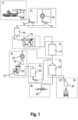
- modules of a plant for producing wood pellets are framed by dashed lines.
- the modules preferably consist of one or more containers in which the components of the plant are contained. In the example, this is the case with modules 1, 2, 5, 6, 8 and 9.
- Module 3 comprises a drying plant according to the invention and modules 4 and 7 are silos in the example.
- Raw material such as sawdust or wood chips
- the raw material is delivered by truck and unloaded in the raw material receiving unit 11. If necessary, the raw material is stored in a place sorted by quality or properties and fed to the system in suitable mixtures, for example by means of a wheel bearing.
- the raw material is fractionated using the sieve 12. The coarse fraction is crushed in the wet shredder 13. After crushing in the wet shredder 13 and after passing through a sieve 14, the fine fraction, together with the fine fraction from the sieve 12, reaches the buffer and dosing container 15.
- the material is dried in the drying system 16 and then temporarily stored in the storage silo 17. This is followed by a metered conveyance to a drying mill 18, where the material is crushed to the optimum grain size.
- the material is then prepared for pressing in a conditioner 19. After passing through a mixing screw 20, in which binding agent is added if necessary, the prepared raw material is fed into a press 21.
- hot pellets are cooled in a cooler 22 and placed in a storage silo 23 for storage. After storage in the storage silo 23, the pellets are packed in small containers in a packaging system 24 or loaded directly as bulk goods in a loading system 25.
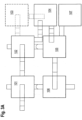
- Fig. 2a and b the temperatures of the drying gas in degrees Celsius and the moisture content of the material in weight percent are recorded at various points in the system.
- ambient air with a temperature of 10°C and 70% relative humidity is fed into the system.
- the material fed in consists of wood chips with a water content of 45% by weight and an average particle size in the range of 30 to 50 mm.
- the material to be dried passes successively through a first drying unit 101, a second drying unit 102, an intermediate shredder 103, a rest container 104, a third drying unit 105 and a cooling unit 106.
- ambient air is heated in a gas preparation unit 107 and fed as a second preheated drying gas to the third drying unit 105.
- the second drying gas cooled by heating the material in the third drying unit 105 to a temperature above the ambient temperature is fed to the second drying unit 102 in order to dry the material fed to this drying unit from the first drying unit 101.
- the cooling unit 106 is supplied with ambient air to cool the material heated during drying in the third drying unit 105.
- the ambient air heated in the cooling unit 106 is fed to the first drying unit 101 as the first drying gas in order to pre-dry the material fed to it.
- the material pre-dried in the first drying unit 101 is further dried in the second drying unit 102.
- the material is crushed in the crushing unit 103 to expose the moisture on the surface of the material. It is then stored in the rest container 103 for a certain rest period of, for example, one to one and a half hours so that the liquid is evened out across the cross section of the particles.
- the material is finally dried in the third drying unit 105. Finally, it is cooled in the cooling unit 106.
- the dried material then goes into storage silo 17.
- the first drying gas cooled in the first drying unit 101 is discharged into the environment.
- the second drying gas cooled in the second drying unit 102 is discharged into the environment.
- the second drying gas cooled and moistened in the second drying unit 102 is fed to a gas drying unit 108.
- the gas temperature is lowered, for example by spraying with water, and vapor condensation is carried out.
- the condensed water from the sump of the gas drying unit 108 can be fed to a heat pump, which brings the heat energy to a suitable temperature level for the drying gas preparation.
- the drying gas dried in the gas drying unit 108 is mixed with the ambient air in the gas preparation unit 107.
- the gas preparation unit 107 of the alternatives from Fig. 2A works with a heat exchanger, which is supplied with heating medium at a temperature of e.g. 100°C, which leaves the heat exchanger at e.g. 60°C.
- the second drying gas is heated to a temperature of approx. 80°C.
- the alternative of Fig. 2B has a burner.
- the fuel is, for example, dried and finely chopped Biomass (e.g. wood dust). This design is particularly suitable and preferred for installation and locations without or with insufficient external heat sources (CHP (combined heat and power) plants, process waste heat, etc.).
- CHP combined heat and power
- a further advantage of the gas preparation unit 107 with burner is the improvement in operational safety, since the use of the low-oxygen exhaust gas from the gas preparation unit 107 provides fire protection in a quasi-circulating operation. Only the amount of air required for the complete combustion of the fuel is supplied, so that the hot fuel gas (e.g. approx. 600°C to 800°C) is mixed with the dried drying gas from the gas drying unit 108 to form a second drying gas with the desired drying gas temperature (approx. 100°C) and fed to the third drying stage 105. Heating the drying gas to a temperature of max. 120°C, preferably max. 100°C, reduces or at least reduces the volatilization of energy-rich components of the material that are important for the production of wood pellets, such as lignin. In addition, the low drying temperature reduces the risk of fire.
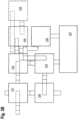
- the gas preparation unit 107 has a cuboid-shaped housing 201 with heat exchangers 203, each of which is gas-permeable in the horizontal direction, arranged in four vertical side walls 202 at a distance from the lower end.
- Each heat exchanger 203 comprises a plate-shaped register 204, which is arranged in the opening 205 of a side wall 202.
- the heat exchangers 203 also comprise a tube bundle 206, which is designed as a spirally wound tube coil with a vertical winding axis.
- a fan 207 with a vertical air inlet 208 and a radial air outlet 209 through a side wall of the housing is arranged in the housing 201.
- the gas preparation unit 107 is designed as a container 210, i.e. it has the dimensions of a standard container.
- the side walls 202 are an integral part of the container shell. Inspection flaps 211 are provided at the bottom of one of the side walls.
- the Container 210 can be transported in a horizontal position. In operation it has the Fig.4 shown vertical alignment.
- the blower 207 sucks in the ambient air to be heated through the registers 204 and the tube bundle 206. As it passes through the registers 204, the ambient air is preheated and reheated as it passes through the tube bundle 206.
- the preheated drying gas passes from the gas preparation unit 107, for example, into the third drying unit.
- the tube bundle 206 is preferably designed as a finned tube bundle and serves as a second heating stage. Hot water or another suitable liquid/mixture is first passed through the tube bundle 206 and then through the registers 204. After passing through the registers 204, the cooled medium is returned to the external heat source as return flow.
- the registers 204 are preferably finned heating registers.
- the blower 207 is, for example, a radial fan or a side channel compressor.
- the gas preparation unit 107 has a particularly good use of floor space and an improved use of the supplied heat.
- the arrangement of the heat exchangers 203 in the upper area reduces the load on the Gas preparation unit 107 with ground dust reduced by stirring up. This increases the efficiency of the heat exchangers 203 and extends the cleaning intervals.
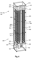
- the shaft dryer 101, 102, 105 has a central vertical gas shaft 301 and drying shafts 302, 303 on both sides of the gas shaft. On the two outer sides of the drying shafts 302, 303, the shaft dryer has outer gas shafts 304, 305.
- the gas shafts 301, 304, 305 and drying shafts 301, 303 are separated from each other by perforated shaft walls 306, 307, 308, 309, which are preferably designed as perforated plates.
- the drying shafts 302, 303 and gas shafts 301, 304, 305 each have a substantially rectangular cross-section.
- Shut-off devices 310 with adjustable passage cross-sections are arranged within the gas shafts 301, 304, 305, which are designed as lamella devices, each with at least one lamella 311 that can be continuously pivoted about a horizontal axis. In the example, there are three lamellas 311 per shut-off device 310.
- shut-off devices 310 are arranged in the vertical direction at three positions distributed approximately evenly over the height of the shaft dryer.
- Drying gas is supplied to the central gas shaft at the bottom via an inlet line 312 and a distribution funnel 313.
- collecting lines 314, 315 are provided through which the moistened and cooled drying gas reaches a discharge line 316.
- the material to be dried is fed via a filling device, which is designed, for example, as a vertical screw 317. Near the lower end, the screw 317 captures fed material and transports it to near the upper end of the shaft dryer 101, 102, 105. There, the material is fed to distribution devices 318, which feed it to the upper ends of the two drying shafts 302, 303.
- a filling device which is designed, for example, as a vertical screw 317. Near the lower end, the screw 317 captures fed material and transports it to near the upper end of the shaft dryer 101, 102, 105.
- the material is fed to distribution devices 318, which feed it to the upper ends of the two drying shafts 302, 303.
- each shaft wall 306, 307, 308, 309 of the drying shafts 302, 303 is guided on their vertical edges on vertical guide devices.
- each shaft wall 306, 307, 308, 309 is connected to a displacement device 319 which is designed to raise and lower the shaft wall vertically, for example over a distance of a few centimeters (e.g. 5 to 10 cm).
- the displacement devices are synchronized so that they displace the walls that border the same drying shaft 302, 303 in opposite directions.
- Each displacement device 319 is, for example, a hydraulic displacement device, in particular a hydraulic cylinder.
- each displacement device 319 is arranged in a gas shaft 301, 304, 305.
- each drying shaft 302, 303 there is a slotted bottom 320 through which dried material can be discharged in a controlled manner.
- the discharged material is guided into a collection and discharge screw 323 by means of a screw bottom 321, 322.
- the refilling of the drying shafts 302, 303 is regulated so that the drying shafts are completely filled with the material to be dried and no false air is created.
- the shaft walls 306, 307, 308, 309 are perforated so that material cannot pass through sideways and fall into a gas shaft 301, 304, 305.
- the drying gas enters the central gas shaft 301 through the inlet line 312 and the distribution funnel 313 and flows across the perforated shaft walls 306, 307, 308, 309 through the drying shafts 302, 303.
- the drying gas enters the collecting lines 314, 315 through the outer gas shafts 304, 305 and is then discharged through the discharge line 316.
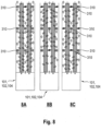
- the drying gas is guided and distributed in the drying shafts 302, 303 by means of the shut-off devices 310. These can be opened more or less. This makes it possible to adjust the guidance of the drying gas over the different height sections of the drying shafts 302, 303 depending on the material properties (particle size, bulk density, etc.) and the throughput (kg per hour) of the material to be dried.
- a simple crossing of the drying shaft 302, 303 can be advantageous, as shown in Fig. 8A
- a single or multiple crossing can be advantageous, as in Fig. 8B and C shown.
- Fine particles which inadvertently enter the gas shafts 304, 305 can be removed by means of screws 324, 325 which are located at the lower end of the outer drying shafts 304, 305.
- drying gas is guided according to Fig. 8B and C advantageous for partial load operation or when the system is designed for lower hourly outputs. It is possible to design the system with only two drying stages instead of three.
- the shaft dryer 101, 102, 105 is formed in a single container 326.
- the outer walls of the shafts 301 to 305 simultaneously form parts of the shell of the container 326.
- the container 326 can be transported horizontally and is vertically erected during operation, as shown in the Figures 6 to 8 shown.
Landscapes
- Engineering & Computer Science (AREA)
- Mechanical Engineering (AREA)
- General Engineering & Computer Science (AREA)
- Life Sciences & Earth Sciences (AREA)
- Microbiology (AREA)
- Drying Of Solid Materials (AREA)
- Chemical And Physical Treatments For Wood And The Like (AREA)
Priority Applications (1)
| Application Number | Priority Date | Filing Date | Title |
|---|---|---|---|
| PL15753322.5T PL3317601T3 (pl) | 2015-07-02 | 2015-07-02 | Sposób i instalacja do przetwarzania i suszenia stałych, drobnocząsteczkowych materiałów |
Applications Claiming Priority (1)
| Application Number | Priority Date | Filing Date | Title |
|---|---|---|---|
| PCT/EP2015/065100 WO2017001019A1 (de) | 2015-07-02 | 2015-07-02 | Verfahren und anlage zum aufbereiten und trocknen von festen kleinstückigen materialien |
Publications (3)
| Publication Number | Publication Date |
|---|---|
| EP3317601A1 EP3317601A1 (de) | 2018-05-09 |
| EP3317601B1 true EP3317601B1 (de) | 2024-06-19 |
| EP3317601C0 EP3317601C0 (de) | 2024-06-19 |
Family
ID=53900787
Family Applications (1)
| Application Number | Title | Priority Date | Filing Date |
|---|---|---|---|
| EP15753322.5A Active EP3317601B1 (de) | 2015-07-02 | 2015-07-02 | Verfahren und anlage zum aufbereiten und trocknen von festen kleinstückigen materialien |
Country Status (14)
| Country | Link |
|---|---|
| US (1) | US20180187973A1 (pl) |
| EP (1) | EP3317601B1 (pl) |
| JP (1) | JP2018525595A (pl) |
| KR (1) | KR20180022887A (pl) |
| CN (1) | CN107820559A (pl) |
| AU (1) | AU2015400474A1 (pl) |
| BR (1) | BR112017027981A2 (pl) |
| CA (1) | CA2990958A1 (pl) |
| EA (1) | EA201890102A1 (pl) |
| ES (1) | ES2985616T3 (pl) |
| MX (1) | MX2018000260A (pl) |
| PL (1) | PL3317601T3 (pl) |
| WO (1) | WO2017001019A1 (pl) |
| ZA (1) | ZA201708705B (pl) |
Families Citing this family (3)
| Publication number | Priority date | Publication date | Assignee | Title |
|---|---|---|---|---|
| US11465833B2 (en) * | 2018-05-14 | 2022-10-11 | Haber Technologies, Inc. | Assembly for saturating a medium with a fluid |
| AT524167A3 (de) * | 2020-09-07 | 2022-08-15 | Johannes Schörkhuber | Verfahren zur herstellung von holzpellets |
| FR3158606A1 (fr) * | 2024-01-31 | 2025-08-01 | Ets Jules N'haux Et Fils | Séchoir modulaire mixte pour céréales en grains et en épis |
Citations (1)
| Publication number | Priority date | Publication date | Assignee | Title |
|---|---|---|---|---|
| US2764819A (en) * | 1952-09-04 | 1956-10-02 | Zander & Ingestroem | Method for drying granular material |
Family Cites Families (16)
| Publication number | Priority date | Publication date | Assignee | Title |
|---|---|---|---|---|
| US1359301A (en) * | 1920-08-26 | 1920-11-16 | Topf J A & Soehne | Drying apparatus |
| JPS5747620Y2 (pl) * | 1978-06-06 | 1982-10-19 | ||
| US4620556A (en) * | 1983-04-12 | 1986-11-04 | Conwood Corporation | Loose leaf chewing tobacco |
| JPS61101394U (pl) * | 1984-12-06 | 1986-06-28 | ||
| FR2630621B1 (fr) * | 1988-04-29 | 1994-06-10 | Socoa | Sechoir a grain |
| WO2005028977A1 (en) * | 2003-09-25 | 2005-03-31 | Maddingley Coldry Pty Ltd | Dryer, drying method and drying plant |
| DE102006061340B3 (de) | 2006-12-22 | 2008-05-08 | Gausling, Ludger | Verfahren und Einrichtung zum Herstellen von Holzpellets sowie Einrichtung zum Trocknen |
| DE102007005782B3 (de) * | 2007-02-06 | 2008-02-14 | Uhde Gmbh | Verfahren und Anlage zur Trocknung von staubförmigen, insbesondere einer Vergasung zuzuführenden Brennstoffen |
| US7818894B2 (en) * | 2007-10-15 | 2010-10-26 | Noyes Ronald T | Method and apparatus for low-energy in-bin cross-flow grain and seed air drying and storage |
| US20100088920A1 (en) * | 2008-10-10 | 2010-04-15 | Larou Albert M | Harvest drying method and apparatus |
| US8449724B2 (en) * | 2009-08-19 | 2013-05-28 | Andritz Technology And Asset Management Gmbh | Method and system for the torrefaction of lignocellulosic material |
| CN103380342A (zh) * | 2010-12-15 | 2013-10-30 | Gtl能源控股有限公司 | 干燥生物质和含碳材料的方法 |
| JP5802582B2 (ja) * | 2012-03-15 | 2015-10-28 | 株式会社東芝 | 汚泥乾燥炭化システム |
| PL2647935T3 (pl) * | 2012-04-03 | 2017-02-28 | Ab Akron-Maskiner | Układ do suszenia ziarna i sposób suszenia ziarna |
| HUE035348T2 (en) * | 2012-10-12 | 2018-05-02 | Stela Laxhuber Gmbh | Drying system for bulk material with an air intake unit |
| DE102013224204A1 (de) | 2013-11-27 | 2015-05-28 | CEBCON GmbH | Anlage zur Herstellung von Holzpellets oder anderen festen Granulaten aus kleinstückigem Material organischen/pflanzlichen Ursprungs |
-
2015
- 2015-07-02 AU AU2015400474A patent/AU2015400474A1/en not_active Abandoned
- 2015-07-02 ES ES15753322T patent/ES2985616T3/es active Active
- 2015-07-02 JP JP2017567676A patent/JP2018525595A/ja active Pending
- 2015-07-02 BR BR112017027981A patent/BR112017027981A2/pt not_active Application Discontinuation
- 2015-07-02 KR KR1020187002611A patent/KR20180022887A/ko not_active Withdrawn
- 2015-07-02 CN CN201580081340.4A patent/CN107820559A/zh active Pending
- 2015-07-02 PL PL15753322.5T patent/PL3317601T3/pl unknown
- 2015-07-02 CA CA2990958A patent/CA2990958A1/en not_active Abandoned
- 2015-07-02 MX MX2018000260A patent/MX2018000260A/es unknown
- 2015-07-02 WO PCT/EP2015/065100 patent/WO2017001019A1/de not_active Ceased
- 2015-07-02 US US15/740,479 patent/US20180187973A1/en not_active Abandoned
- 2015-07-02 EP EP15753322.5A patent/EP3317601B1/de active Active
- 2015-07-02 EA EA201890102A patent/EA201890102A1/ru unknown
-
2017
- 2017-12-20 ZA ZA2017/08705A patent/ZA201708705B/en unknown
Patent Citations (1)
| Publication number | Priority date | Publication date | Assignee | Title |
|---|---|---|---|---|
| US2764819A (en) * | 1952-09-04 | 1956-10-02 | Zander & Ingestroem | Method for drying granular material |
Also Published As
| Publication number | Publication date |
|---|---|
| ZA201708705B (en) | 2018-11-28 |
| ES2985616T3 (es) | 2024-11-06 |
| AU2015400474A1 (en) | 2018-01-25 |
| KR20180022887A (ko) | 2018-03-06 |
| CA2990958A1 (en) | 2017-01-05 |
| JP2018525595A (ja) | 2018-09-06 |
| EA201890102A1 (ru) | 2018-07-31 |
| US20180187973A1 (en) | 2018-07-05 |
| EP3317601A1 (de) | 2018-05-09 |
| MX2018000260A (es) | 2018-03-08 |
| CN107820559A (zh) | 2018-03-20 |
| BR112017027981A2 (pt) | 2018-08-28 |
| WO2017001019A1 (de) | 2017-01-05 |
| PL3317601T3 (pl) | 2024-11-12 |
| EP3317601C0 (de) | 2024-06-19 |
Similar Documents
| Publication | Publication Date | Title |
|---|---|---|
| DE102015108742B4 (de) | Verfahren und Vorrichtung zum Aufbereiten von organischen Festbrennstoffen, insbesondere Waldhackschnitzeln | |
| EP3074118B1 (de) | Anlage zur herstellung von holzpellets oder anderen festen granulaten aus kleinstückigem material organischen/pflanzlichen ursprungs | |
| AT510487B1 (de) | Trocknungsverfahren und trocknungssystem | |
| EP2326900B1 (de) | Verfahren und vorrichtung zum trocknen von biomasse | |
| WO2011026642A1 (de) | Verfahren und anlage zur herstellung von pellets aus biomasse in einer pelletierpresse zur verwendung als brennmaterial in feuerstellen | |
| EP3317601B1 (de) | Verfahren und anlage zum aufbereiten und trocknen von festen kleinstückigen materialien | |
| DE3015250C2 (de) | Verfahren und Einrichtung zur Aufbereitung von Mineralfaserschrott unterschiedlicher Beschaffenheit, insbesondere hinsichtlich seiner organischen Bestandteile | |
| WO1993007101A1 (de) | Verwendung einer maschine zur gipskartonplattenwiederaufarbeitung | |
| EP1849851B1 (de) | Pellettieranlage | |
| DE102009059971B4 (de) | Vorrichtung zum Lagern, Bearbeiten und Austragen von schwer fliessenden Schüttgütern | |
| EP2985339B1 (de) | Gärrest-Konditionierer und Verfahren zur Konditionierung von Gärresten | |
| EP3535203B1 (de) | Silo, verfahren zum begasen von schüttgut | |
| DE102006061340B3 (de) | Verfahren und Einrichtung zum Herstellen von Holzpellets sowie Einrichtung zum Trocknen | |
| DE102017120043C5 (de) | Anlage und Verfahren zur Herstellung von beleimten Pflanzenpartikeln | |
| DE102020000818A1 (de) | Verwertung von ausgefaultem Klärschlamm in einer Wirbelschichtanlage | |
| AT503111B1 (de) | Pellettieranlage | |
| CH646729A5 (en) | Process and apparatus for drying active yeast | |
| WO2023061662A1 (de) | Mobile trocknungsanlage und trocknungssystem | |
| EP3640572A2 (de) | Verfahren und vorrichtung zur trocknung von feuchtem holz und dergleichen mit verbesserter abgasqualität | |
| EP2395306A2 (de) | Verfahren und Vorrichtung zur Trocknung von Fasergut, insbesondere Holzhackschnitzeln | |
| DE102017104431B4 (de) | Verfahren und Vorrichtung zur Herstellung eines Einstreumaterials aus Waldhackschnitzeln für einen Stall, Einstreumaterial und Verwendung eines definierten Feinanteils von Waldhackschnitzeln als Einstreumaterial für einen Stall | |
| EP4733277A1 (de) | Trocknung von klärschlamm | |
| EP1698846B1 (de) | Anlage und Verfahren zum Trocknen von schüttgutförmigem Holzmaterial | |
| DE102017009465A1 (de) | Einrichtung und Verfahren zur Aufbereitung von Biomasse |
Legal Events
| Date | Code | Title | Description |
|---|---|---|---|
| STAA | Information on the status of an ep patent application or granted ep patent |
Free format text: STATUS: THE INTERNATIONAL PUBLICATION HAS BEEN MADE |
|
| PUAI | Public reference made under article 153(3) epc to a published international application that has entered the european phase |
Free format text: ORIGINAL CODE: 0009012 |
|
| STAA | Information on the status of an ep patent application or granted ep patent |
Free format text: STATUS: REQUEST FOR EXAMINATION WAS MADE |
|
| 17P | Request for examination filed |
Effective date: 20180202 |
|
| AK | Designated contracting states |
Kind code of ref document: A1 Designated state(s): AL AT BE BG CH CY CZ DE DK EE ES FI FR GB GR HR HU IE IS IT LI LT LU LV MC MK MT NL NO PL PT RO RS SE SI SK SM TR |
|
| AX | Request for extension of the european patent |
Extension state: BA ME |
|
| DAV | Request for validation of the european patent (deleted) | ||
| DAX | Request for extension of the european patent (deleted) | ||
| STAA | Information on the status of an ep patent application or granted ep patent |
Free format text: STATUS: EXAMINATION IS IN PROGRESS |
|
| 17Q | First examination report despatched |
Effective date: 20190613 |
|
| GRAP | Despatch of communication of intention to grant a patent |
Free format text: ORIGINAL CODE: EPIDOSNIGR1 |
|
| STAA | Information on the status of an ep patent application or granted ep patent |
Free format text: STATUS: GRANT OF PATENT IS INTENDED |
|
| INTG | Intention to grant announced |
Effective date: 20240409 |
|
| GRAS | Grant fee paid |
Free format text: ORIGINAL CODE: EPIDOSNIGR3 |
|
| GRAA | (expected) grant |
Free format text: ORIGINAL CODE: 0009210 |
|
| STAA | Information on the status of an ep patent application or granted ep patent |
Free format text: STATUS: THE PATENT HAS BEEN GRANTED |
|
| AK | Designated contracting states |
Kind code of ref document: B1 Designated state(s): AL AT BE BG CH CY CZ DE DK EE ES FI FR GB GR HR HU IE IS IT LI LT LU LV MC MK MT NL NO PL PT RO RS SE SI SK SM TR |
|
| REG | Reference to a national code |
Ref country code: GB Ref legal event code: FG4D Free format text: NOT ENGLISH |
|
| REG | Reference to a national code |
Ref country code: CH Ref legal event code: EP |
|
| REG | Reference to a national code |
Ref country code: DE Ref legal event code: R096 Ref document number: 502015016869 Country of ref document: DE |
|
| RAP4 | Party data changed (patent owner data changed or rights of a patent transferred) |
Owner name: CEBCON TECHNOLOGIES GMBH |
|
| U01 | Request for unitary effect filed |
Effective date: 20240718 |
|
| U07 | Unitary effect registered |
Designated state(s): AT BE BG DE DK EE FI FR IT LT LU LV MT NL PT SE SI Effective date: 20240726 |
|
| U20 | Renewal fee for the european patent with unitary effect paid |
Year of fee payment: 10 Effective date: 20240808 |
|
| PG25 | Lapsed in a contracting state [announced via postgrant information from national office to epo] |
Ref country code: HR Free format text: LAPSE BECAUSE OF FAILURE TO SUBMIT A TRANSLATION OF THE DESCRIPTION OR TO PAY THE FEE WITHIN THE PRESCRIBED TIME-LIMIT Effective date: 20240619 |
|
| PG25 | Lapsed in a contracting state [announced via postgrant information from national office to epo] |
Ref country code: GR Free format text: LAPSE BECAUSE OF FAILURE TO SUBMIT A TRANSLATION OF THE DESCRIPTION OR TO PAY THE FEE WITHIN THE PRESCRIBED TIME-LIMIT Effective date: 20240920 |
|
| PG25 | Lapsed in a contracting state [announced via postgrant information from national office to epo] |
Ref country code: HR Free format text: LAPSE BECAUSE OF FAILURE TO SUBMIT A TRANSLATION OF THE DESCRIPTION OR TO PAY THE FEE WITHIN THE PRESCRIBED TIME-LIMIT Effective date: 20240619 Ref country code: GR Free format text: LAPSE BECAUSE OF FAILURE TO SUBMIT A TRANSLATION OF THE DESCRIPTION OR TO PAY THE FEE WITHIN THE PRESCRIBED TIME-LIMIT Effective date: 20240920 Ref country code: RS Free format text: LAPSE BECAUSE OF FAILURE TO SUBMIT A TRANSLATION OF THE DESCRIPTION OR TO PAY THE FEE WITHIN THE PRESCRIBED TIME-LIMIT Effective date: 20240919 |
|
| REG | Reference to a national code |
Ref country code: ES Ref legal event code: FG2A Ref document number: 2985616 Country of ref document: ES Kind code of ref document: T3 Effective date: 20241106 |
|
| PG25 | Lapsed in a contracting state [announced via postgrant information from national office to epo] |
Ref country code: IS Free format text: LAPSE BECAUSE OF FAILURE TO SUBMIT A TRANSLATION OF THE DESCRIPTION OR TO PAY THE FEE WITHIN THE PRESCRIBED TIME-LIMIT Effective date: 20241019 |
|
| PG25 | Lapsed in a contracting state [announced via postgrant information from national office to epo] |
Ref country code: CZ Free format text: LAPSE BECAUSE OF FAILURE TO SUBMIT A TRANSLATION OF THE DESCRIPTION OR TO PAY THE FEE WITHIN THE PRESCRIBED TIME-LIMIT Effective date: 20240619 |
|
| PG25 | Lapsed in a contracting state [announced via postgrant information from national office to epo] |
Ref country code: SK Free format text: LAPSE BECAUSE OF FAILURE TO SUBMIT A TRANSLATION OF THE DESCRIPTION OR TO PAY THE FEE WITHIN THE PRESCRIBED TIME-LIMIT Effective date: 20240619 Ref country code: RO Free format text: LAPSE BECAUSE OF FAILURE TO SUBMIT A TRANSLATION OF THE DESCRIPTION OR TO PAY THE FEE WITHIN THE PRESCRIBED TIME-LIMIT Effective date: 20240619 |
|
| PG25 | Lapsed in a contracting state [announced via postgrant information from national office to epo] |
Ref country code: SM Free format text: LAPSE BECAUSE OF FAILURE TO SUBMIT A TRANSLATION OF THE DESCRIPTION OR TO PAY THE FEE WITHIN THE PRESCRIBED TIME-LIMIT Effective date: 20240619 |
|
| PG25 | Lapsed in a contracting state [announced via postgrant information from national office to epo] |
Ref country code: SM Free format text: LAPSE BECAUSE OF FAILURE TO SUBMIT A TRANSLATION OF THE DESCRIPTION OR TO PAY THE FEE WITHIN THE PRESCRIBED TIME-LIMIT Effective date: 20240619 Ref country code: SK Free format text: LAPSE BECAUSE OF FAILURE TO SUBMIT A TRANSLATION OF THE DESCRIPTION OR TO PAY THE FEE WITHIN THE PRESCRIBED TIME-LIMIT Effective date: 20240619 Ref country code: RO Free format text: LAPSE BECAUSE OF FAILURE TO SUBMIT A TRANSLATION OF THE DESCRIPTION OR TO PAY THE FEE WITHIN THE PRESCRIBED TIME-LIMIT Effective date: 20240619 Ref country code: IS Free format text: LAPSE BECAUSE OF FAILURE TO SUBMIT A TRANSLATION OF THE DESCRIPTION OR TO PAY THE FEE WITHIN THE PRESCRIBED TIME-LIMIT Effective date: 20241019 Ref country code: CZ Free format text: LAPSE BECAUSE OF FAILURE TO SUBMIT A TRANSLATION OF THE DESCRIPTION OR TO PAY THE FEE WITHIN THE PRESCRIBED TIME-LIMIT Effective date: 20240619 |
|
| PG25 | Lapsed in a contracting state [announced via postgrant information from national office to epo] |
Ref country code: MC Free format text: LAPSE BECAUSE OF FAILURE TO SUBMIT A TRANSLATION OF THE DESCRIPTION OR TO PAY THE FEE WITHIN THE PRESCRIBED TIME-LIMIT Effective date: 20240619 |
|
| PG25 | Lapsed in a contracting state [announced via postgrant information from national office to epo] |
Ref country code: MC Free format text: LAPSE BECAUSE OF FAILURE TO SUBMIT A TRANSLATION OF THE DESCRIPTION OR TO PAY THE FEE WITHIN THE PRESCRIBED TIME-LIMIT Effective date: 20240619 |
|
| PLBE | No opposition filed within time limit |
Free format text: ORIGINAL CODE: 0009261 |
|
| STAA | Information on the status of an ep patent application or granted ep patent |
Free format text: STATUS: NO OPPOSITION FILED WITHIN TIME LIMIT |
|
| 26N | No opposition filed |
Effective date: 20250320 |
|
| PGFP | Annual fee paid to national office [announced via postgrant information from national office to epo] |
Ref country code: PL Payment date: 20250626 Year of fee payment: 11 |
|
| PG25 | Lapsed in a contracting state [announced via postgrant information from national office to epo] |
Ref country code: IE Free format text: LAPSE BECAUSE OF NON-PAYMENT OF DUE FEES Effective date: 20240702 |
|
| U20 | Renewal fee for the european patent with unitary effect paid |
Year of fee payment: 11 Effective date: 20250717 |
|
| PGFP | Annual fee paid to national office [announced via postgrant information from national office to epo] |
Ref country code: ES Payment date: 20250819 Year of fee payment: 11 |
|
| PGFP | Annual fee paid to national office [announced via postgrant information from national office to epo] |
Ref country code: NO Payment date: 20250725 Year of fee payment: 11 |
|
| PGFP | Annual fee paid to national office [announced via postgrant information from national office to epo] |
Ref country code: GB Payment date: 20250722 Year of fee payment: 11 |
|
| PGFP | Annual fee paid to national office [announced via postgrant information from national office to epo] |
Ref country code: CH Payment date: 20250801 Year of fee payment: 11 |
|
| PG25 | Lapsed in a contracting state [announced via postgrant information from national office to epo] |
Ref country code: CY Free format text: LAPSE BECAUSE OF FAILURE TO SUBMIT A TRANSLATION OF THE DESCRIPTION OR TO PAY THE FEE WITHIN THE PRESCRIBED TIME-LIMIT; INVALID AB INITIO Effective date: 20150702 |
|
| PG25 | Lapsed in a contracting state [announced via postgrant information from national office to epo] |
Ref country code: HU Free format text: LAPSE BECAUSE OF FAILURE TO SUBMIT A TRANSLATION OF THE DESCRIPTION OR TO PAY THE FEE WITHIN THE PRESCRIBED TIME-LIMIT; INVALID AB INITIO Effective date: 20150702 |