EP3317624B1 - Système et étiquettes de caractérisation et d'identification optiques - Google Patents
Système et étiquettes de caractérisation et d'identification optiques Download PDFInfo
- Publication number
- EP3317624B1 EP3317624B1 EP16820949.2A EP16820949A EP3317624B1 EP 3317624 B1 EP3317624 B1 EP 3317624B1 EP 16820949 A EP16820949 A EP 16820949A EP 3317624 B1 EP3317624 B1 EP 3317624B1
- Authority
- EP
- European Patent Office
- Prior art keywords
- spectral
- tag
- tags
- structural
- color
- Prior art date
- Legal status (The legal status is an assumption and is not a legal conclusion. Google has not performed a legal analysis and makes no representation as to the accuracy of the status listed.)
- Active
Links
Images








Classifications
-
- G—PHYSICS
- G06—COMPUTING OR CALCULATING; COUNTING
- G06K—GRAPHICAL DATA READING; PRESENTATION OF DATA; RECORD CARRIERS; HANDLING RECORD CARRIERS
- G06K19/00—Record carriers for use with machines and with at least a part designed to carry digital markings
- G06K19/06—Record carriers for use with machines and with at least a part designed to carry digital markings characterised by the kind of the digital marking, e.g. shape, nature, code
- G06K19/06009—Record carriers for use with machines and with at least a part designed to carry digital markings characterised by the kind of the digital marking, e.g. shape, nature, code with optically detectable marking
- G06K19/06037—Record carriers for use with machines and with at least a part designed to carry digital markings characterised by the kind of the digital marking, e.g. shape, nature, code with optically detectable marking multi-dimensional coding
-
- G—PHYSICS
- G01—MEASURING; TESTING
- G01J—MEASUREMENT OF INTENSITY, VELOCITY, SPECTRAL CONTENT, POLARISATION, PHASE OR PULSE CHARACTERISTICS OF INFRARED, VISIBLE OR ULTRAVIOLET LIGHT; COLORIMETRY; RADIATION PYROMETRY
- G01J3/00—Spectrometry; Spectrophotometry; Monochromators; Measuring colours
- G01J3/12—Generating the spectrum; Monochromators
-
- G—PHYSICS
- G01—MEASURING; TESTING
- G01J—MEASUREMENT OF INTENSITY, VELOCITY, SPECTRAL CONTENT, POLARISATION, PHASE OR PULSE CHARACTERISTICS OF INFRARED, VISIBLE OR ULTRAVIOLET LIGHT; COLORIMETRY; RADIATION PYROMETRY
- G01J3/00—Spectrometry; Spectrophotometry; Monochromators; Measuring colours
- G01J3/28—Investigating the spectrum
- G01J3/2823—Imaging spectrometer
-
- G—PHYSICS
- G06—COMPUTING OR CALCULATING; COUNTING
- G06K—GRAPHICAL DATA READING; PRESENTATION OF DATA; RECORD CARRIERS; HANDLING RECORD CARRIERS
- G06K19/00—Record carriers for use with machines and with at least a part designed to carry digital markings
-
- G—PHYSICS
- G06—COMPUTING OR CALCULATING; COUNTING
- G06K—GRAPHICAL DATA READING; PRESENTATION OF DATA; RECORD CARRIERS; HANDLING RECORD CARRIERS
- G06K19/00—Record carriers for use with machines and with at least a part designed to carry digital markings
- G06K19/06—Record carriers for use with machines and with at least a part designed to carry digital markings characterised by the kind of the digital marking, e.g. shape, nature, code
- G06K19/06009—Record carriers for use with machines and with at least a part designed to carry digital markings characterised by the kind of the digital marking, e.g. shape, nature, code with optically detectable marking
- G06K19/06018—Record carriers for use with machines and with at least a part designed to carry digital markings characterised by the kind of the digital marking, e.g. shape, nature, code with optically detectable marking one-dimensional coding
- G06K19/06028—Record carriers for use with machines and with at least a part designed to carry digital markings characterised by the kind of the digital marking, e.g. shape, nature, code with optically detectable marking one-dimensional coding using bar codes
-
- G—PHYSICS
- G06—COMPUTING OR CALCULATING; COUNTING
- G06K—GRAPHICAL DATA READING; PRESENTATION OF DATA; RECORD CARRIERS; HANDLING RECORD CARRIERS
- G06K19/00—Record carriers for use with machines and with at least a part designed to carry digital markings
- G06K19/06—Record carriers for use with machines and with at least a part designed to carry digital markings characterised by the kind of the digital marking, e.g. shape, nature, code
- G06K19/06009—Record carriers for use with machines and with at least a part designed to carry digital markings characterised by the kind of the digital marking, e.g. shape, nature, code with optically detectable marking
- G06K19/06046—Constructional details
- G06K19/0614—Constructional details the marking being selective to wavelength, e.g. color barcode or barcodes only visible under UV or IR
-
- G—PHYSICS
- G01—MEASURING; TESTING
- G01J—MEASUREMENT OF INTENSITY, VELOCITY, SPECTRAL CONTENT, POLARISATION, PHASE OR PULSE CHARACTERISTICS OF INFRARED, VISIBLE OR ULTRAVIOLET LIGHT; COLORIMETRY; RADIATION PYROMETRY
- G01J3/00—Spectrometry; Spectrophotometry; Monochromators; Measuring colours
- G01J3/28—Investigating the spectrum
- G01J3/2823—Imaging spectrometer
- G01J2003/2826—Multispectral imaging, e.g. filter imaging
Definitions
- the Invention relates to the automatic identification, tracking and/or characterization of macroscopic entities by means of spectral imaging and optically encoded tags, markers or labels worn by, painted over or attached to the entities.
- the entities may include subjects such as human beings and animals, items such as bags and packages, manufacturing or catalogue parts, road vehicles, traffic signs, or any other macroscopic objects, which makes the invention suited to a broad range of applications.
- the invention is applicable to fields such as: object identification and tracking, logistics, warehousing, supply chain management, Internet of Things, personnel identification in hospitals, cleanrooms, production facilities, attendee tracking & profiling at conferences, trade shows and events, surveillance, defense & security (friend or foe ID, airport passenger tracking & security, access control), manufacturing, assembly, construction (alignment, position & orientation control), remote sensing, social networks (automatic person tagging on Facebook), advertising & promotion, disabled access & safety (audio warnings for the blind), automotive (assisted driving, traffic & law enforcement), virtual / augmented reality (3D filming, reconstruction & depth perception), clickable hypervideo, digital rights management, and more.
- fields such as: object identification and tracking, logistics, warehousing, supply chain management, Internet of Things, personnel identification in hospitals, cleanrooms, production facilities, attendee tracking & profiling at conferences, trade shows and events, surveillance, defense & security (friend or foe ID, airport passenger tracking & security, access control), manufacturing, assembly
- the Invention can benefit a great many aspects of the physical environment where machines need to remotely interpret and analyze entities that surround them by means of a computer vision and object tagging system.
- the Invention has the potential to create a self-describing world that will be intelligible to computers enabling them to respond to various events and situations, thereby unlocking innumerable computer and machine vision applications in many environments such as buildings (airports, train and bus stations, offices, hospitals, prisons, police stations, conferences, exhibitions), urban settings (traffic, parking, congestion charging), operations centers (mail sorting, logistics, transport hubs), manufacturing (factories, cleanrooms, assembly floors, construction sites), and military (secure facilities, army bases, theaters of operations).
- Optical tags can be provided as, e.g., barcodes, QR codes or other features with data storage capacity.
- Passive optical tags are typically encoded in the spatial domain, as in ubiquitous bar codes and QR codes. However, it requires that the spatial code be either in direct proximity to the scanner, or well-focused and accurately positioned in front of a camera.
- None of the available solutions provide an encodable optical identification solution for macroscopic physical entities (objects and subjects) that can be reliably and accurately decoded by an imaging solution as a low-cost, real-time, video-rate system under relaxed acquisition conditions such as arbitrary distance and observation angle.
- Teachings of the present Invention can overcome the above limitations by providing both a spectral imaging solution and an encodable optical identification solution that (a) are spectrally matched to each other, i.e., the imaging solution is highly selective to the tagging solution and uniquely identifies it against the background or other materials, and (b) the tagging solution uses photonic and structural colors, rather than natural or chemical pigment ones, to engineer unique spectral signatures allowing ample information to be encoded through a photonic spectral coding scheme.
- structural coloration refers to purpose-engineered photonic materials and metamaterials whose optical spectral properties (collectively referred to as "color", even though they may include invisible wavelengths) are defined by their structural parameters such as the size, fill factor, and periodicity of nanoscale layers, features, patterns and arrays thereof.
- Structural coloration is found in nature, with the example of the reflection spectrum of pigeon neck feathers shown in Fig. 2(a) [1], while Fig. 2(b) demonstrates the same effect using man-made material structures [2]. Both Fig. 2(a) and (b) serve to illustrate the significant spectral shift, or color travel, caused by a variable angle of observation (gonio-dependence).
- Other techniques of imparting structural coloration include nanostructure-patterned surfaces as reported in [3].
- the Invention teaches how to provide information encoding in the spectral, rather than spatial, domain by use of structural coloration and information decoding by a remote imaging system.
- Structural colors arise from specific light-matter interaction mechanisms such as interference, diffraction, refraction, iridescence, photonic crystal phenomena, photonic bandgap phenomena, and plasmonic phenomena, and are different by nature from commonplace pigment colors that are defined by selective absorption of light in materials. Pigment colors require different chemical recipes and are therefore limited to established material compositions; by contrast, structural colors can be photonic-engineered and allow substantially greater freedom in generating unique spectra by structural design within a common material system and manufacturing technology.
- a further advantage is that high-contrast, sharp spectral features can be generated by structural coloration, which are typically absent from the spectra of most background materials.
- the Invention makes non-obvious adaptations of various elements of the art that have been developed or proposed for use in unrelated applications or different fields.
- silk particles as proposed for use in cosmetics and medical applications by US Pat. App. 20130243693 ; optically variable paints and dyes for color shift effects and iridescence as per US Pat. 5,059,245 and thin films as per US Pat. 4,705,356 ; photonic crystals for visual effects as per US Pat. 6,939,605 ; quasi-periodic filters for detection of substances as per US Pat. 5,059,026 and 5,218,422 ; complementary comb filters for night vision as per US Pat.
- spectral tags with a high gonio-dependence are used to provide angular and volumetric imaging.
- spectrally-resolved 3-dimensional imaging by means of spectrocolorimetry is disclosed in US Pat. 5,502,799 , or by means of time-in-flight LIDAR at different wavelengths in US Pat. App. 20140085622 .
- a technique of gonio-spectral imaging to record the reflectance spectra, gloss and texture of 3D objects is taught in US Pat. 6,249,751 .
- Plenoptic and light-field cameras are also used for 3D and multi-focus imaging as in US Pat. 8,400,555 .
- spectral tags with a temperature dependence are used to provide stand-off temperature sensing of tagged objects, which is advantageous over high-cost thermal imagers that are conventionally deployed in this application.
- Certain implementations of the Invention allow transformation of entity recognition and characterization from a spatial image (such as a QR/barcode, or any form of spatial pattern matching) into an optical spectral code.
- a spatial image such as a QR/barcode, or any form of spatial pattern matching
- tailor-made spectral signatures, or codes can be realized by structural design alone without the limitations of conventional formula-dependent colorants, pigments or dyes.
- the unique, high-contrast features in the spectral signatures achievable by structural coloration afford straightforward differentiation of the tagging media from all common background materials.
- the Intention teaches specific types of structural coloration that can provide the spectral properties necessary for such differentiation.
- certain aspects of the Invention make use of imaging spectroscopy, where the imaged scene need not be in focus and as little as one areal pixel suffices to identify and decode a spectral code.
- some of the disclosed spectral decoding methods are different from conventional hyperspectral data processing, where large swathes of land or material are classified by their spectral appearance.
- a static identity code can be traded for a dynamic property code that carries information on angle, strain, humidity, temperature, gas or chemical substance concentration, paving the way for passive and low-cost sensors for a myriad of applications.
- the invention in its various aspects typically offers one or more of the following advantages over incumbent object identification, tracking, and characterization technologies:
- Certain embodiments of the invention teach a system for an automatic line-of-sight identification and/or characterization of remote macroscopic entities and their properties by means of structural-color tags worn by, painted over or attached to the entities.
- the entities may include subjects such as human beings and animals, items such as bags and packages, manufacturing or catalogue parts, road vehicles, signs, or any other macroscopic objects, which makes the invention suited to a broad range of applications.
- the structural-color tags are defined by photonic taggants with spectral signatures engineered by structural coloration using Fabry-Perot, interference, diffraction and plasmonic effects. The tags encode information through their spectral properties, and are identified and interpreted using a spectral camera.
- Spectrally matched active illumination is also provided to identify and distinguish the tags from the background.
- Tags with a gonio-dependent spectral signature can be used to remotely reconstruct the profile of a surface or orientation of an entity.
- the invention can thus provide stand-off object characterization and tracking based on the associated tag or tags including the identity, location, orientation, speed, temperature, strain, deformation, humidity, elapsed time, gas and chemical substance concentration, shape and surface profile.
- tag refers to an object, or a region of an object that has properties allowing it to perform as a tagging element according to an aspect of the teachings of the present invention. This may be a stand-alone structure, a sticker, tape, powder, fabric or other element applied to a surface of an object, or may be provided by processing or applying a material to a surface of an object, such as by application of a paint, which imparts the required properties to the surface.
- color or "structural color” denote spectral properties of an object or surface and may include wavelengths in the infrared region. The use of such terms is borrowed from visible light terminology, although clearly no “color” is visible at infrared wavelengths
- Various aspects of the Invention encompass a system comprising three complementary aspects, namely, a tagging aspect, an imaging aspect, and a processing aspect.
- the tagging aspect is provided by one or more optically coded tags (markers or labels) T1, T2, .... defined by photonic taggants PT1, PT2, .... placed on an object or subject;
- the imaging aspect is provided by a spectral camera SC for imaging a scene possibly containing an object or subject marked with tags T1, T2, ....;
- the processing aspect is a method performed by a processing unit PU for the decoding and analysis of said tags and, by association, of the tagged object or subject.
- Modes 1a/b and 3 can be combined to achieve enhanced functionality, e.g., by combining Modes 1a/b and 3 one can obtain a system that both tracks subjects and provides a video output showing their location.
- Some imaging embodiments can be combined too, e.g., spectral range-finder SRF of embodiment ImE3 can be added to any other embodiment.
- a combination of tag embodiments can be placed on a subject or object, e.g., one tag for identification and another for characterization, which will combine the functionalities of Modes 1a/b and 2.
- Fig. 3 The system disclosed in Fig. 3 is a demonstrative, non-limiting schematic exemplifying a preferred embodiment of the Invention. It should be noted that the schematic of Fig. 3 is provided as an aid to understanding the concept and operation of a preferred embodiment, while a more formal presentation will be given in Fig. 4 . With reference to Table 1, the system configuration of Fig. 3 represents a combination of Best Modes 1a/b and 3, whereas the system configuration of Fig. 4 represents a combination of Best Modes 1a/b, 2 and 3.
- the system of Fig. 3 includes spectral camera SC that is capable of imaging a scene in N distinct spectral channels Ch 1 ... Ch N , where each channel represents either a single or multiple spectral bands.
- the spectral camera SC is operatively connected to processing unit PU for acquisition control and image processing.
- processing unit PU Located at a distance of several meters (typically, 3 - 300 meters) from camera SC are two subjects, a man and a dog, wearing structural-color tags T1...T3 (man) and T4 (dog), with the tags' optical properties, including their spectral signature, defined by the photonic-engineered taggants they contain.
- the use of taggants with structural color, or structure-defined optical properties as opposed to chemically or compositionally defined ones, allows a large plurality of custom spectral signatures to be created by photonic engineering.
- the scene is illuminated by active illuminator AI, which provides an illumination cone substantially filling the field of view FoV of the spectral camera SC.
- the tags T1...T4 may be provided in retro-reflective format to maximize the return efficiency of the illumination impinging on the tags in a wavelength-selective fashion, said illumination having an optical spectrum associated with some or all spectral channels Ch 1 ... Ch N and/or the tags' spectral signatures.
- Multiple tags can be placed on a subject or object to increase the reliability of detection, e.g., T1 and T2.
- tags T1 and T2 have a high visibility when viewed in spectral channels Ch 1 and Ch 2 but little or no visibility in Ch N .
- the variation in the tags' visibility across different spectral channels allows information to be encoded in analog or binary format, with a Boolean "1" assigned when the visibility in a specific spectral channel exceeds a certain threshold, or a "0" when below threshold ("11...0" associated with tag T1 ).
- Some channels may be used for reference, verification and/or error correction.
- more digital levels e.g., visibility or intensity grades from 0 to 9 could be used to identify or characterize a tag with a substantially higher information capacity.
- thresholding can be performed by comparing (subtracting and/or dividing) images recorded in different spectral channels to quantify the tag visibility modulation between them.
- Mathematical operations such as computation of the first or second derivatives of the spectral data can be used to highlight sharp visibility variation across different spectral channels.
- image analysis and thesholding are performed by the processing unit PU, which can not only establish the presence of a tag (if specific threshold conditions are met), but also output the tag's identity or properties based on the information encoded therein, which, in turn, can be augmented by the lookup of the tag's information in a local or remote database or resource, e.g., over the Internet.
- tags may include their orientation, tilt, depth, distance, surface profile, temperature, humidity, elapsed time, gas or chemical agent concentration, deformation and strain.
- a monochrome image for human observation can be obtained by outputting a specific spectral channel of the spectral camera SC.
- a false or real-color image can be generated using SC' s specific spectral channels mapped as red, green, blue (RGB) components.
- a conventional visible light camera VLC either color or monochrome
- Such a system can generate a video stream ("Video data” in Fig. 3 ) provided by the visible light camera VLC and enrich it with tag data provided by the spectral camera SC, said data (“Object data” in Fig. 3 ) containing information about the tagged objects and/or subjects referenced to their position within the video frames.
- knowledge of the identity of an object or subject of interest and its location or movement may be used to control either or both cameras VLC and SC, e.g., by providing a motorized mount to tilt or pan a camera for real-time tracking.
- Either camera can perform actions for image acquisition improvement such as auto-focus or flash activation, e.g., using information on the position of a subject of interest.
- a computer or processing unit associated with a camera can execute transmission of an image or alert message. Therefore, such a system will possess advanced computer / machine vision capabilities whereby the processing unit PU can obtain and process information about the identity and properties of tagged entities by image acquisition of remote scenes in a straightforward, line-of-sight manner.
- Such capabilities lie beyond the reach of state-of-the art vision systems and are afforded by a non-trivial integration, and non-obvious adaptation of, spectral imaging and photonic engineering technologies as will be explained in the following sections.
- Fig. 4 A similarly operated configuration is illustrated in Fig. 4 , which provides a more formal and generalized presentation of the preferred embodiment of the Invention.
- the components outlined with solid lines are indispensable constituents of the system, whereas the parts outlined with dashed lines are optional and their inclusion in the system is warranted by application requirements.
- spectral range-finder SRF may be used to determine the distance to the tagged object based on a unique spectral response of structural-color tags T1 and/or T2 and also double as an auto-focus device to enhance the image quality.
- the visible light camera VLC may be provided if video output is desired in addition to tagged object data. Illumination is preferentially provided by active illuminator AI co-located with the spectral camera SC but can also come from another suitable light source, e.g., controlled ambient lighting.
- the active illuminator AI emits optical radiation of power ⁇ s ( ⁇ )d ⁇ , where s ( ⁇ ) is the power spectral density of the radiation and ⁇ is the wavelength.
- the wavelength integration limits are associated with a specific spectral range SSR, which may be defined by one or more of the following techniques: by a filter integrated with camera SC, by spectral channels Ch 1 ... Ch N , by the spectral sensitivity of camera SC, by the spectral bandwidth of active illuminator AI.
- structural-color tags T1 and/or T2 which reflect some of the illumination impinging thereon in a wavelength-selective fashion.
- the tags contain structural-color taggants to provide spectral signatures in the form of variable reflectivity r ( ⁇ , ⁇ ) that is dependent on wavelength ⁇ and possibly angle ⁇ , the latter defined as the angle of incidence (or reflection) of illumination versus a normal to wavelength-selective elements within the structural-color taggant.
- the optical power returned to the camera SC is proportional to ⁇ s ( ⁇ ) r ( 0 , ⁇ ) d ⁇ .
- the optical power returned to the camera SC is proportional to ⁇ s ( ⁇ ) r ( ⁇ , ⁇ ) d ⁇ .
- the gonio-dependence of spectral response r ( ⁇ , ⁇ ) on angle ⁇ can be either an undesirable feature (as in object or subject identification) or a desirable one (as in stand-off profilometry and characterization of orientation, rotation or tilt), therefore different imaging and tagging embodiments will be provided that either suppress or enhance this feature.
- Spectral camera SC captures N spectrally-discriminated images of a scene possibly containing a structural-color tag or tags with a spectral signature substantially defined by s ( ⁇ ) r ( ⁇ , ⁇ ), which results in variable visibility in accordance with the spectral properties of its spectral channels Ch 1 ... Ch N .
- the captured image data are analyzed by processing unit PU, which performs a spectral analysis of an areal portion of the spectrally-discriminated images that may be as small as one pixel in size or as large as the whole camera sensor area.
- the image data are subjected to numerical processing, which may include operations on pixel values such as scaling, subtraction, normalizing, binning, unmixing, denoising, Fourier transform, thresholding, including a comparison (e.g., subtraction, division, differentiation) of images recorded in different spectral channels.
- a high difference, differential, derivative or ratio between specific spectral channels may indicate the presence of a structural-color tag and can be used to screen pixels or areas of a scene prior to detailed classification, identification or characterization and as illustrated in the optimized algorithm of Fig. 6 .
- the algorithm according to the block diagram of Fig. 6 is particularly suitable if high differentials, derivatives or ratios are sought between specific spectral bands defined by respective spectral channels where the tag spectral signatures are expected to exhibit a high modulation of visibility, as illustrated in Fig. 7 .
- speed and efficiency optimization can be achieved by screening the spectral image data for above-threshold differentials [as in Fig. 7(c) ] or ratios prior to performing the tag identification or characterization cycle.
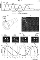
- FIG. 7 A rotating shaft bearing a round structural-color tag T1 is shown in Fig. 7(b) , with the tag's spectral signature having a sharp spectral modulation represented by the solid line of Fig. 7(a) .
- typical background materials exhibit smooth or slow-varying spectra such as the dashed lines in Fig. 7(a) .
- the brightness of background materials merely affects their intensity level in the spectrum, but not their spectral modulation.
- the processing diagrams of Fig. 5 and Fig. 6 further include matching the resulting spectral data to stored thresholds, differentials, derivatives, codes or signatures and, if a match is obtained, outputting information associated with the identified tag.
- information may include any digital identifier, value, reference or index conveying the identity of an entity in an areal portion of the scene as well as its spatial extent and coordinates.
- the angular dependence of the imaged spectral signature s ( ⁇ ) r ( ⁇ , ⁇ ) may be used to infer the orientation and rotation of the tag and of the object or subject it is attached to.
- the tag's temperature t can be inferred if its spectral signature r t contains a known thermal dependence r t ( ⁇ , ⁇ , t ).
- Other physical characteristics such as humidity, elapsed time, gas or chemical agent concentration, strain and deformation can be associated with the respective spectral signature dependence of the tag.
- processing unit PU obtains illuminated spectral signatures s ( ⁇ ) r ( 0 , ⁇ ) and s ( ⁇ ) r ( ⁇ , ⁇ ) of structural-color tags T1 and T2 , respectively, in the respective areal portions of the imaged scene, processes and identifies them by matching them to stored data, and outputs information pertaining to tags T1 and T2 .
- the nature of processing, identification and output information may differ depending on the application and specific imaging and tagging embodiments.
- the tags' gonio-dependence should be minimized (as will be taught in tagging embodiments TgE2 and TgE3 ), in which case both tags T1 and T2 will point to a common identifier substantially defined by s ( ⁇ ) r ( ⁇ ).
- the spectral signature r ( ⁇ ) can be deconvolved by calibrating the spectral camera against a known illumination spectrum s ( ⁇ ) obtained, e.g., by imaging a uniformly illuminated white area.
- processing embodiment PrE1 can thus provide tag information that includes the identity, position, size, orientation, speed of a tagged entity, with further information obtainable from a local or remote storage or network resource based on the identity of the subject or object.
- tag information may contain a website link to a social network like Facebook, where more details about the tagged person may be retrieved.
- the person's image may be automatically highlighted or tagged on a social network.
- the tags' gonio-dependence should be maximized (as will be taught in tagging embodiment TgE4 ), in which case the system will recognize tag T2 as a rotated version of tag T1 tag by matching an angle ⁇ to the imaged signature s ( ⁇ )r( ⁇ , ⁇ ).
- Processing embodiment PrE1 can thus provide tag information that includes tilt, angle, orientation, shape, and even depth profile of a tagged surface. Similar processing can be performed for any temperature, humidity, elapsed time, time, gas or chemical agent concentration, strain and deformation dependence of a tag's spectral signature, allowing the tag to be used as a sensor for measuring such dependence.
- the system of Fig. 4 operating according to embodiment PrE1 as described in Fig. 5 or Fig. 6 is capable of both automatically identifying one or several of a set of known structural-color tags within its field of view and outputting information pertaining to the identified tags and/or the objects / subjects associated with them.
- a spectral camera SC can be realized by modification of some of the designs of hyperspectral and multispectral imagers developed for medical and remote sensing applications. It is important that, unlike most of the prior art employing (hyper)spectral cameras in scanning regime, or single shot regime, the present Invention is advantageously practised using spectral imagers operating in real-time at substantially video rates, video rate being defined for real-time purposes as 1 frame per second or higher. Such imagers are disclosed, for example, in US Pat. 7,130,041 , 8,233,148 , and US Pat. App. 20120327248 .
- spectral camera SC acts substantially as a hyperspectral imager producing images in spectral channels Ch 1 ... Ch N that are formed by an image sensor or focal plane array disposed behind either a plurality of narrowband transmission filters or, in some hyperspectral imager designs, a single tunable passband transmission filter that is tuned through a plurality of spectral configurations.
- the acquired spatio-spectral dataset is commonly represented as a hyperspectral cube, which comprises a plurality of spatial X-Y images obtained in spectral bands Ch 1 ... Ch N as illustrated in Fig. 18(b) .
- spectral bands are usually engineered to be of substantially equal spectral width with a uniform spacing to provide a regular spectral sampling of a specific spectral region of interest, with a hyperspectral camera operating substantially as an imaging spectrometer for acquiring a hyperspectral cube in spatial axes (X, Y) and one spectral axis (wavelength or frequency).
- both the center positions ⁇ k of the spectral windows and their bandwidths ( ⁇ Hk - ⁇ Lk ) may be at least partially matched to high and low intensity wavelength components within the spectral signatures of the tags to be imaged.
- embodiment ImE1 is illustrated in Fig. 8(a) , where two structural-color tags, square ( T1 ) and round ( T2 ), are imaged with a hyperspectral camera having spectral channels Ch 1 ... Ch N with spectral properties as illustrated in (b).
- Ch N of the spectral camera one should try to obtain preferential or exclusive transmission of intensity peaks and troughs from the tag spectra in as many spectral channels as possible, with a view to obtaining spectral images that are either substantially bright or dark, just as the tags T2 and T1 , respectively, appear in the image of Ch 3 in Fig. 8(a) .
- Intermediate or grayscale images, such as T1 's appearance in Ch 2 should be avoided as these possess insufficient contrast and are more prone to classification errors.
- tags should have spectral signatures consisting of one or more characteristic spectral feature.
- a feature should include at least one sharp transition between a high-intensity level and a low-intensity level differing by 20% or more, as can be seen in the tag spectra of Fig. 8(b) .
- the sharpness of such a transition can be defined in reference to a spectral bandwidth covering adjacent two or more spectral channels, e.g., tag T2 (dashed line) exhibits a high spectral modulation between Ch 2 and Ch 3 , while tag T1 (solid line) between Ch 1 and Ch 3 .
- transition bandwidth (but not narrower than ( ⁇ k + 1 - ⁇ k ) for the respective spectral channels) and the higher the spectral modulation depth, the better the discrimination against common background materials that can be achieved. It is estimated that transition bandwidths of 80nm or smaller centered at a wavelength of 900nm, or 50nm or smaller at 700nm, provide sufficiently sharp spectral modulation for easy differentiation against the background. Expressed in wavenumber terms, such a bandwidth corresponds to 1000 inverse centimeters or less.
- Fig. 9 A mathematical description of the above principles is provided in Fig. 9 , where the spectral transmission of the k -th channel is represented by the filter transfer function F k ( ⁇ ) defined within the limits [ ⁇ Lk , ⁇ Hk ].
- the filter transfer function F k ( ⁇ ) should ideally approach 1 within the interval [ ⁇ Lk , ⁇ Hk ], and 0 outside, i.e., behave like a boxcar function. In reality, however, the filter transfer function F k ( ⁇ ) typically exhibits sloped edges as illustrated in Fig. 9 .
- the total power sliced by the k -th channel Ch k from an illuminated tag's spectral signature s ( ⁇ ) r ( ⁇ , ⁇ ) is therefore ⁇ ⁇ Lk ⁇ Hk s ⁇ r ⁇ ⁇ F k ⁇ d ⁇ .
- the task of photonic engineering is therefore to both maximize this integral in some spectral channels, and minimize it in different spectral channels, by an appropriate choice of channel boundaries [ ⁇ Lk , ⁇ Hk ] , and spectral signatures r ( ⁇ , ⁇ ) of structural-color tags.
- an implementation of the Invention makes use of the Fabry-Perot etalon effect in some of its imaging and tagging embodiments.
- An ideal Fabry-Perot etalon is formed by two parallel, reflecting surfaces separated by physical thickness d filled with a transparent medium of refractive index n .
- a Fabry-Perot effect can also be achieved where the reflecting surfaces are formed by periodic structures, such as quarter-wavelength stacks or Bragg mirrors.
- a structural-color tag may contain a photonic-engineered taggant whose reflective spectral signature r ( ⁇ , ⁇ ) is defined by a Fabry-Perot etalon with optical thickness D according to Eq.1.
- the tag structure may contain multiple layers of different thicknesses and materials as will be explained later, but at least one of the layers can form a Fabry-Perot etalon with a characteristic optical thickness D and spectral signature r ( ⁇ , ⁇ ).
- the spectral signature is represented by the intensities recorded in individual channels as shown in Fig. 10(b) .
- the spectral signature is well-resolved in higher channels / longer wavelengths, but is under-sampled in lower channels / shorter wavelengths resulting in poor tag visibility modulation.
- a modified spectral camera design using narrower spectral bandwidths with a smaller spacing in lower channels would allow the spectral signature to be adequately resolved.
- imaging embodiment ImE1 can employ conventional hyperspectral imaging technology but with preferable customization of spectral channel bandwidths and spacing to match the spectral signatures of imaged tags.
- both the imaging and tagging aspects of the Invention can be spectrally matched to each other by using similarly defined spectral signatures by means of optically similar Fabry-Perot comb etalons, or frequency combs.
- a structural-color tag whose reflective spectral signature r ( ⁇ , ⁇ ) is defined by a Fabry-Perot etalon, in reflection mode, with optical thickness D according to Eq.1, can be imaged by a spectral camera containing a first image filter transfer function F '( ⁇ ' , ⁇ ) ⁇ r ( ⁇ , ⁇ ) also defined by a Fabry-Perot etalon, in transmission mode, with a different optical thickness D ' and M ' as in Eq.2, wherein Eqs.1 and 2 are used with substantially similar or identical M ' ⁇ M and angles ⁇ ⁇ ⁇ '.
- the first image filter will provide high transmission to all high-intensity wavelength components of r ( ⁇ , ⁇ ), which would be equivalent to imaging a highly reflective or white area, or a broadband light source with no spectral signature at all.
- a second, half-period shifted image filter is provided with a function F " ( ⁇ ', ⁇ ) defined by a Fabry-Perot etalon formed in one or more layer, in transmission mode, with a different optical thickness D " obtained by substituting M '-0.5 in Eq.2, thereby transforming it into Eq.1. Therefore, the transmission peaks of the first image filter F '( ⁇ ' , ⁇ ) spectrally overlay the reflection peaks of the second image filter F "( ⁇ ' , ⁇ ) , and vice versa.
- the first image filter By assigning the first image filter to the k -th channel Ch k of a spectral camera, and the second image filter to its ( k + 1 )-st channel Ch k + 1 , one can obtain a high-contrast image of a tag with spectral signature r ( ⁇ , ⁇ ) as defined by Eq.1 by subtracting from the image in channel Ch k (high intensity) the image in channel Ch k + 1 (low intensity). Therefore the tag can be easily detected by image subtraction between specific spectral channels.
- a scaling, division or normalization operation on the two images can also be used to produce a ratio indicative of high image contrast.
- FIG. 11 The operation of such a spectrally matched tag and camera system is illustrated in Fig. 11 .
- the spectral signature contains varying quasi-periodic reflection peaks and is substantially dissimilar to typical reflection spectra exhibited by most natural-color, non-photonic engineered materials.
- Fig. 11 (d-f) shows a truck exiting a tunnel.
- the truck's number plate contains a Fabry-Perot photonic taggant so engineered as to produce a spectral signature similar to that of Fig. 11(b) .
- the number plate When imaged through Filter A in (d), the number plate is highly visible, as are most bright areas in the image, e.g., the lights in the tunnel.
- Filter B in (e) the number plate appears dark, but the other bright areas in the image remain bright as they contain no spectral modulation for Filter B to discriminate against.
- any two adjacent filters in the spectral sequence e.g., M' k+ 1 and M' k , or M' k and M' k -1 , are complementary to each other and differ in their optical thickness by a quarter wavelength ⁇ /4 at normal incidence.
- a differential image obtained with any adjacent filter pair may be used to decode a tag with a Fabry-Perot spectral signature defined by an identical or similar fringe order M .
- a filter within a complementary filter pair can be used as a spectral counterpart to the other, one Fabry-Perot tag per camera spectral channel can be allocated according to its M value, which would imply that the total number of identifiable tags will be similar to the number N of spectral channels Ch 1 ... Ch N .
- a spectral camera based on embodiment ImE2 will recognize a plurality of structural-color tags that is much larger than the camera's channel count N .
- the fringe orders M ' of 32 complementary, half-period shifted filters defined by Eq.2 are enumerated as ⁇ 71.0, 71.5, 72.0, 72.5, ... 86.5 ⁇ .
- M ' ⁇ 71.0, 71.5, 72.0, 72.5, ... 86.5 ⁇
- M ⁇ 50, 53, 57, 62, ... 105 ⁇ .
- variable tag contrast when imaged across a series of complementary filter channels Ch 1 ... Ch N is exploited in processing embodiment PrE2 to greatly augment the number of identifiable tags.
- a tag's signature instead of associating a single tag with a single spectral channel by commonality of their M and M' values, one can correlate a tag's signature with a plurality of its visibility differentials or contrasts between adjacent channels across the whole channel series.
- Such a plurality may form, for example, a one-dimensional array or vector P indexed by channel number k with values containing absolute differentials ⁇
- Such an array or vector P resembles materials classifiers or "spectral signatures" used in hyperspectral and multispectral imaging, however, its physical implementation is very different.
- the Fabry-Perot filter transfer function F k ( ⁇ ) for a k -th channel Ch k of a spectral camera no longer defines a continuous spectral band or window, but rather a quasi-periodic sequence of variable and discontinuous spectral bands or windows, hence such a camera no longer meets the definition of a hyperspectral imager.
- the plurality of spectral windows in a single channel of such a spectral camera will admit considerably more light and provide a higher signal-to-noise ratio than in conventional hyperspectral imager designs, wherein narrowband channel filters are used.
- Such a spectral camera can, nonetheless, be realized using conventional hyperspectral imager designs by simply increasing the thicknesses of internal Fabry-Perot filters to achieve the required values of M '.
- a method for the fabrication of complementary comb filters taught in US Pat. 6,885,504 could be applied to the manufacturing of spectral channel filters in this Invention.
- the processing embodiment PrE2 is fully compatible with PrE1 described earlier in Fig. 5 and Fig. 6 , with the above differentials, derivatives or ratio vector P used for comparison with and identification of imaged tags.
- embodiment PrE2 can also provide a significant improvement in processing speed and efficiency by first screening an imaged scene for pixels where at least some elements in the above vector P are non-zero or exceed a certain threshold (which may vary from channel to channel), as illustrated in the block diagram of Fig. 6 . Fulfillment of the threshold condition would only imply the presence of a tag or tags and will trigger a more computationally intensive comparison cycle where the vector P is matched to stored patterns to identify the tag(s). If the threshold condition is not satisfied, the nugatory comparison cycle is not performed, which improves the system's speed and efficiency.
- the bandwidth of optical radiation used for imaging tags according to embodiment ImE2, wherein a tag's spectral signature is defined by a Fabry-Perot etalon using Eq.1 with fringe order M > 1 should cover several reflection peaks, or free spectral ranges FSR, to achieve maximum contrast within a specific spectral range where filter complementarity is maintained.
- narrowband radiation can be used to interrogate specific peaks and troughs within a tag's spectral signature in embodiments ImE1 and ImE2.
- the tags must be interrogated by light whose coherence length L c is greater than double the etalon's optical thickness D, where L c is related to the bandwidth ⁇ of the interrogating source at center wavelength ⁇ as L c ⁇ ⁇ 2 / ⁇ ⁇ .
- Coherent sources such as laser diodes can be used to perform narrowband tag interrogation, however, the problem of laser speckle in the imaged data would have to be addressed.
- laser tag interrogation can prove useful not for imaging but rather for range-finding applications, which are covered by imaging and processing embodiments ImE3 and PrE3, respectively. If a tag's spectral signature is known to contain specific peaks and troughs as shown in Fig. 13(a) , a laser pulse fired at a peak wavelength ⁇ p will have a high reflective return efficiency.
- a laser pulse fired at an off-peak wavelength ⁇ op will have a low reflective return efficiency.
- the differential return signal between the two wavelengths can be used to measure the distance to the tagged object with high discrimination against the other entities in the background.
- a method is disclosed to measure both the return energy E p , E op and the round-trip time-in-flight delay ⁇ p , ⁇ op of the interrogation laser pulses at wavelengths ⁇ p , ⁇ op , respectively, and if the differential return energy
- a directed light source whose spectrum is likely to have a high return efficiency when reflected by a tagged object, and a light source with a low reflective return efficiency, can be used to perform selective range-finding in reference to the specific tagged object of interest.
- pulsed time-of-flight distance measurement technology at pixel level with a specific active illuminator as disclosed by International Pat. App. WO2014096157 and WO2014068061 , can be spectrally matched to an object of interest.
- the selective range-finding functionality can be added to a spectral camera as an auto-focus apparatus to enable a camera to record an image of a specific object in sharp focus based on its distance.
- LIDAR Light Detection and Ranging
- a spectral speed camera can both identify the vehicle and measure its speed by firing interrogation pulses at characteristic wavelengths within its spectral signature, thereby singling out the vehicle for a speed check amongst all other traffic.
- Other approaches may include use of custom interrogation spectra such as disclosed by US Pat. 8,406,859 , which uses a spatial light modulator to configure a spectrum for active illumination.
- processing embodiment PrE4 disclosed herein and schematized in Fig. 14 .
- the principle of operation lies in the intensity modulation of the active illuminator AI synchronized with the image acquisition cycle of the spectral camera, so as to obtain spectral images of both an illuminated and unilluminated scene, and then subtract the latter from the former to eliminate the background lighting.
- the exact algorithm depends on the implementation of the spectral camera, which can be classified in two broad operation modes.
- the first operation mode will be referred to as snapshot acquisition mode, wherein the camera obtains a complete set of spectral images in channels Ch 1 ... Ch N within a single frame acquisition cycle.
- Such spectral cameras are disclosed in US Pat. App. 20140267849 and 20120327248 .
- Such cameras feature spectral filter arrays overlaying a digital image sensor and associate different pixel groups on the sensor with different spectral channels.
- a first data set ⁇ A k ⁇ containing all spectral channels is acquired simultaneously under active illumination, followed by a second data set ⁇ B k ⁇ acquired without illumination, and a differential data set is obtained by subtracting the images within the second data set from the first.
- the second operation mode will be referred to as sequential acquisition mode, wherein the camera obtains a single spectral channel Ch k within a frame acquisition cycle.
- Such systems may use a filter wheel as in US Pat. 7,835,002 or 8,174,694 , or liquid crystal variable filters as in US Pat. 8,406,859 , or a tunable Fabry-Perot filter that is tuned through different configurations, each defining a spectral channel, as exemplified by WO2014207742 .
- a hyperspectral data set is assembled over time. This type of system is useful for ground-based applications wherein the sensor is stationary; a moving platform will cause spectral mis-registration as the spectrum for each pixel is collected over time. Moving objects in the scene will cause mis-registration as well.
- the acquired spectral data set may form a hyperspectral cube, where images can be stacked according to their wavelength or according to their spectral channel as illustrated in Fig. 18(b) , which may or may not be associated with a single spectral band or wavelength as in embodiments ImE1 and ImE2, respectively.
- the method of processing embodiment PrE4 requires active illuminator AI to be intensity modulated and synchronized with the image acquisition cycles of the spectral camera. Such modulation can be achieved by precise electronic control to trigger the activation and deactivation of the active illuminator with reference to the readout circuitry of the image sensor or focal plane array of the spectral camera.
- the type of source used as AI must lend itself to modulation on the millisecond scale, with suitable semiconductor emitters including light-emitting diodes (LED), diode lasers, vertical-cavity surface-emitting lasers (VCSELs), etc., preferably covering the relevant portions of the visible and near-infrared spectral ranges (400 - 1100 nm in wavelength) where well-established silicon-based image sensors (CCD or CMOS) provide low-cost imaging solutions. Operation in the near-IR range (700 - 1900 nm) may be preferred with active illuminator AI used as a covert source or to avoid visual disturbance due to stroboscopic effects.
- LED light-emitting diodes
- VCSELs vertical-cavity surface-emitting lasers
- Emerging sensor technologies using nanowires or covalent polymer pixels may enable low-cost imaging solutions at infrared wavelengths beyond those of silicon-based sensors.
- quantum cascade lasers could be used for active illumination.
- the divergence of the active illuminator source AI be matched to the field of view FoV of the spectral camera SC.
- a combination of a hyperspectral imager with a filter wheel and an image projector for active illumination is disclosed in European Pat. EP 2749210 .
- Dichroic filters are proposed for filtering active illumination sources in US Pat. 8,792,098 .
- 15(a) illustrates the simulated gonio-spectral drift for three Fabry-Perot tags of optical thicknesses D1 , D2, D3, each corresponding to a fringe order M at normal incidence, allowing the apparent identification in M of the tag on the ordinate axis to be decoded as an angular reading on the abscissa.
- a refractive index of the tag medium n 1.5 is assumed.
- the fringe visibility or contrast defined as the ratio of a visibility maximum to a visibility minimum (a ratio of unity meaning no contrast) rapidly deteriorates with the angle of illumination as seen in the plot of Fig. 15(b) . While many imperfections can contribute to a reduction in the fringe contrast (e.g., a finite reflectivity of the Fabry-etalon surfaces, surface defects or non-parallelism, losses within the etalon medium, illumination beam divergence, etc.), the lateral beam "walk-off' within the etalon has the strongest detrimental effect under oblique illumination as reported in [8].
- the walk-off effect depends on the aspect ratio of the resonator (ratio between its thickness D and width W ) and is strongest for high D / W ratios.
- the resulting fringe contrast decay with increasing angle is illustrated in the example of Fig. 15(b) for a case where all Fabry-Perot tag widths are equal to thickness D3 of the thickest of the three tags. It can be seen that the tag geometry and aspect ratio can be optimized to ensure sufficient fringe visibility under illumination within an angular range of interest.
- a narrow angular interrogation range may be desired to preclude off-axis tag identification for security reasons, or to limit the gonio-spectral drift of Fig. 15(a) by the vanishing tag contrast of Fig. 15(b) so as to prevent tag misidentification at high angles.
- a combination of several tags with different Fabry-Perot thicknesses or aspect ratios on the same surface or object can be used to obtain surface profile, rotational or orientational information in different angular ranges.
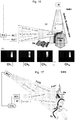
- FIG. 16 presents the forthcoming imaging embodiment ImE4 to demonstrate how the remote angular characterization capability described above could be practised in a real system.
- object Oa bears structural-color tag Ta, with a gonio-dependent spectral signature r a ( ⁇ , ⁇ ), over a whole or part of its surface.
- r a ⁇ , ⁇
- the system of Fig. 4 the system of Fig.
- 16(a) has spectral camera SC (with optional visible light camera VLC ) and active illuminator AI observing and illuminating object Oa along substantially different axes, so as to image tag Ta at non-zero angles of illumination and observation.
- spectral camera SC with optional visible light camera VLC
- active illuminator AI observing and illuminating object Oa along substantially different axes, so as to image tag Ta at non-zero angles of illumination and observation.
- specular reflection angle ⁇ At every illuminated and observable point on tag Ta, there exists a specular reflection angle ⁇ at which the illumination s ( ⁇ ) is deflected towards the spectral camera SC delivering a power proportional to ⁇ s ( ⁇ ) r a ( ⁇ , ⁇ ) d ⁇ .
- the spectral response of a structural-color tag may be observable over an angular range 2 ⁇ around specular reflection angle ⁇ .
- any local deformations, protrusions, depressions, shapes, or features of the surface will therefore produce variable-intensity components from ⁇ s ( ⁇ ) r a ( ⁇ - ⁇ , ⁇ ) d ⁇ to ⁇ s ( ⁇ ) r a ( ⁇ + ⁇ , ⁇ ) d ⁇ that will be readily recorded as variation in the visibility of the corresponding surface features in the spectral images of camera SC as illustrated in Fig. 16(b) .
- Fig. 16(b) one can see what the spectrally discriminated images of the rounded shape of tag Ta may look like in different spectral channels, with a gradation in visibility corresponding to a variation in angle.
- the imaging embodiment ImE4 of Fig. 16 can be generalized to cover many different scenarios, e.g., using other forms of structural coloration that, like the Fabry-Perot effect utilized here, exhibit gonio-dependent spectral signatures, in which case a corresponding gonio-spectral plot should be used instead of Fig. 15 for angular decoding.
- the operation can be extended to imaging complex surface profiles such as those borne by object Ob, which may benefit from having visible light camera VLC provide the illumination intensity distribution to calibrate the spectral images of camera SC .
- spectral cameras SC1 , SC2... with a single active illuminator AI, which is covered by the forthcoming imaging embodiment ImE5 of Fig. 17 .
- the spectral cameras SC1 and SC2 are operatively connected to a central processing unit CPU that performs an analysis of spectral image data acquired from both camera locations.
- Object Oa (flanged beam) marked with planar structural-color tag Ta having spectral signature r a ( ⁇ , ⁇ ) is observed by both cameras SC1 and SC2 by virtue of its presence within both of their fields of view FoV1 and FoV2, respectively.
- the two cameras will receive different spectral visibilities of the tag as ⁇ s ( ⁇ ) r a ( ⁇ , ⁇ ) d ⁇ optical powers and ⁇ s ( ⁇ ) r a ( ⁇ , ⁇ ) d ⁇ , where the angles ⁇ and ⁇ need not lie in the same plane, i.e., an arbitrary orientation about any axis of rotation is possible.
- object Oa depicted as a flanged beam being loaded by a crane the observation of its planar structural-color tag Ta by both cameras SC1 and SC2 can remotely provide complete positional information about all six degrees of freedom of the beam (X, Y, Z, pitch, yaw, and roll orientation), which can facilitate its precise loading and placement by the crane operator (or, potentially, render the loading process fully automatic).
- imaging embodiment ImE5 can also apply to non-planar or deformable tags such as distributed tag Tb (e.g., glitter) having spectral signature r b ( ⁇ , ⁇ ) and covering the clothing of dancer Ob in Fig. 17 .
- distributed tag Tb e.g., glitter
- r b spectral signature
- r b covering the clothing of dancer Ob in Fig. 17 .
- Each point on the tagged clothing is perceived as either ⁇ s ( ⁇ ) r b ( ⁇ , ⁇ ) d ⁇ or ⁇ s ( ⁇ ) r b ( ⁇ , ⁇ ) d ⁇ corresponding to the observation angles ⁇ and ⁇ of cameras SC1 and SC2.
- the positional and orientational information on the dancer's body and posture can be deduced from the spectral image data, allowing the dancer's movements to be remotely tracked and recorded, e.g., for dance recreation or gait analysis in a virtual reality environment, or for gesture recognition and control in a human-machine interface. It may also be advantageous to have a visible light camera (shown as VLC in Fig. 16 ) record the scene from a spectral camera location to complement the spectral image data.
- VLC visible light camera
- a spectral camera and a visible light camera share a common field of view in the imaging embodiments mentioned above, which will allow the tagged objects identified or characterized by the spectral camera to be associated with their visual appearance in the images captured by the visible light camera. While the two cameras can be placed next to each other, their observation points and fields of view will be somewhat different.
- UK Pat. GB 2,373,943 teaches a method of combining image sensors with an infrared field of view and a visible field of view to share a common field of view, but where the infrared image sensor is not a multi-channel spectral camera. This type of design is conceptually similar to the well-established single lens reflex camera technology (see, e.g., US Pat. 4,047,206 ) where a common field of view is shared by the image sensor (or photographic film) and the viewfinder.
- a spectrally broadband image of a scene is formed by imaging optics IFO that may include lenses, apertures, image replicators, filters.
- the image rays are divided by beamsplitter BS between visible camera sensor VCS and spectral camera sensor SCS, which are both located in the image planes of imaging optics IFO.
- spectral filters SF Disposed between BS and SCS are a plurality of spectral filters SF, or a single filter tunable through a plurality of spectral configurations (e.g., a filter wheel or a tunable Fabry-Perot etalon), to define the spectral channels on spectral camera sensor SCS.
- spectral configurations e.g., a filter wheel or a tunable Fabry-Perot etalon
- the spectral range analyzed by spectral camera sensor SCS determines the spectral properties of beamsplitter BS.
- beamsplitter BS can provide high reflection at angles of incidence of around 45° for wavelengths within specific spectral range SSR, with a high transmission for wavelengths outside this range, i.e., act as a spectrally selective mirror.
- the spectral range analyzed by the spectral camera covers parts of both visible and infrared spectra
- beamsplitter BS can be partially transmitting and reflecting to feed the same wavelengths both for imaging by visible camera sensor VCS and spectral analysis by spectral camera sensor SCS.
- the reflection spectrum of beamsplitter BS can be engineered to provide higher reflectivities to feed more power to SCS (which typically requires longer exposures due to the spectral filtering involved) within the spectral overlap region, and either maximum transmission (in the visible) or maximum reflection (in the infrared) outside the spectral overlap region.
- the locations of the two image sensors VCS and SCS in Fig. 18 can be swapped with a corresponding reversal of the transmission and reflection requirements for beamsplitter BS.
- imaging embodiment ImE6 enables a registration of tagged objects and their properties as identified by spectral camera sensor SCS onto the image output produced by visible camera sensor VCS.
- This capability can provide enriched video streams with associated object data, e.g., video frames with metadata on entities present within each frame as well as their properties and location.
- Fig. 18(b) provides a graphic representation of a plurality of spectral images recorded in channels Ch 1 ... Ch N of a spectral camera used to form a data set for spectral analysis.
- the camera is a hyperspectral one and its k -th channel is associated with a single narrow spectral band centered at wavelength ⁇ k , then such a data set is typically called a hyperspectral data cube, where spatial (X-Y) images of a scene are arrayed along a spectral axis in wavelength A.
- the channels Ch 1 ... Ch N may define spectral windows of variable spectral width and at irregular intervals as taught in imaging embodiment ImE1, or even a plurality of quasi-periodic spectral windows for each channel as in embodiment ImE2.
- the variable visibility of a particular spatial pixel in different spectral channels is then used to identify or characterize a structural-color tag in processing embodiments PrE1 and PrE2.
- Fig. 18(c) illustrates a much spectrally smaller data set obtained by a visible light color camera.
- 3 primary colors red, green and blue, or RGB
- three further spectral channels are made available for the same pixel (or substantially the same spatial area of the imaged scene), similarly to the larger data cube of Fig. 18(b) .
- Higher spatial resolution and higher frame rates are also usually available with conventional color cameras than with spectral or hyperspectral ones, which is advantageous for providing human-perceptible video output.
- Visible light cameras with higher color resolution than afforded by conventional RGB imagers can be used here to an advantage, too.
- Both (b) and (c) serve to illustrate a multi-spectral imaging capability obtained by a combination of data sets (b)+(c).
- a known structural-color tag is placed at a known spatial location of a scene so that the tag's image occupies known spatial pixel(s) (or region of interest) in the acquired spectral images as Fig. 18(b) .
- the tag's manifestation in the region of interest across different spectral channels may be subjected to numerical processing, which may include operations on pixel values such as scaling, subtraction, normalizing, binning, unmixing, denoising, thresholding, Fourier transform and the like.
- the resulting spectral data is then stored as a threshold, pattern, code, signature, vector, array or sequence and associated with the tag's identity and/or any of its properties such as angle, orientation, illumination or temperature.
- any of the tag's properties or conditions are modified, e.g., the tag is rotated through a known angle, or the illumination conditions are changed, or the tag is moved to a different position or distance, and the spectral data acquisition and association process is repeated, and so on. Not all changes or adjustments may need to be performed at each iteration, with optional steps shown in the dashed boxes in Fig. 19 .
- the same training cycle can be performed for all or most parameter variations within the anticipated operational ranges, e.g., of distance and temperature, and for all tags that require accurate identification or characterization.
- the processing unit of a spectral camera can then match newly acquired spectral data with stored data with reference to the identity or property of a known tag to identify or characterize any new instances of the same tag using processing embodiments PrE1 or PrE2.
- tags refers to an object, or a region of an object that has properties allowing it to perform a tagging, labeling or sensing function. This may be a standalone structure, a sticker, tape, powder, fabric or other element applied to a surface of an object, or may be provided by processing or applying a material to a surface of an object, such as by application of a paint, which imparts the required properties to the surface.
- Tag embodiments of the Invention typically contain a photonic taggant, which is formed by one or more photonic structures that impart structural coloration to the tag and define its spectral signature.
- a tag may be synonymous with a taggant and simply refer to a quantity of, or surface coverage by, such a taggant.
- a tag may include a photonic taggant and other elements such as optics or reflective surfaces.
- coloration and “color” are used here to refer to the generic spectral properties or signatures that may or may not include visible colors.
- Several methods of imparting structural coloration are known is the art, and some of them will be adapted for use in the tagging aspect of the Invention in the embodiments below.
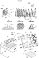
- One approach includes light interference phenomena that occur in thin films and layers, with principal methods represented in the cross-sectional views and corresponding spectral patterns of Fig. 20 .
- a thin transparent layer TL having a refractive index that is different from that of the surrounding medium, so at to effect a light reflection at its top and bottom interfaces.
- Its optical thickness may range from a quarter-wavelength to multiple wavelengths according to Eq.1.
- the layer When illuminated by a substantially collimated optical source, the layer will act as a Fabry-Perot etalon providing quasi-periodic transmission and reflection spectra.
- Such films include polymer layers such as polyamide and polyurethane, dielectric films such as silica, titania (anatase or rutile) and zirconia, and thin crystalline plates and platelets, e.g., of natural mica or synthetic mica.
- dielectric films such as silica, titania (anatase or rutile) and zirconia
- thin crystalline plates and platelets e.g., of natural mica or synthetic mica.
- the reflectivity of the interfaces is insufficient to produce sharp spectra or frequency combs, with only a limited spectral modulation as illustrated in Fig. 20(a) .
- Fig. 20(b) shows how coating a substrate such as a platelet or flake TL1 with a thin transparent layer TL2 can also create a more pronounced light interference effects, with a larger spectral modulation depth and sharper transitions.
- Metal oxides of Cu, Zn, Zr, Fe, Cr deposited onto mica, alumina, silica, calcium, aluminum, borosilicate substrates or flakes are now commercially available as interference media, e.g., from Glassflake Ltd., UK, under the name of Moonshine series.
- Lamellar glass flakes can be processed with wet chemical coating technologies such as Sol-Gel dip coating to apply dielectric and metallic layers for desired optical effects.
- AMIRAN glass for architectural applications contains an anti-reflection interferometric coating applied by Sol-Gel technology.
- additional reflecting layers RL can be provided on one or both optical surfaces of the transparent layer TL as shown in Fig. 20(c) .
- Transparent layer TL may be formed by a dielectric layer of Al2O3, TiO2, SiO2, MgF2, Nb2O5, BiOCl, BaTiO3, ZnO or a polymer layer of 2-methyl-4-nitroaniline, polystyrene/collodion, polystyrene/polyvinyl alcohol, polymethylmethacrylate, PMMA, PET, polyethylene, polyethylene 2,6 naphthalate (PEN), polyethylene terephthalate, polybutylene naphthalate (PBN), polyester, polyamide, polyurethane.
- a reflecting layer RL may be formed by thin layers of metals such as Al, Ag, Au, Cu, Cr, Fe, Ni, Zn.
- High-reflectivity mirrors can be formed not just by highly reflective metal layers but also stacked combinations of dielectric layers, as taught in US Pat. App. 20130155515 .
- stacked dielectric coatings containing multiple quarter-wavelength pairs of low and high refractive index transparent layers, shown as TL1 and TL2, in Fig. 20(e) have found widespread use in various spectral coating designs, e.g., as taught in US Pat. 8,630,040 . Their design and implementation are well understood in the art, with many textbooks available, e.g., [10].
- a high index contrast between alternating layers and a large layer count very high-reflectivity, large-bandwidth reflection bands (known as photonic bandgaps) can be created as illustrated in Fig. 20(e) .
- Such periodic layer stacks are known as Bragg mirrors and form volume, or bulk, diffraction gratings, where constructive light interference leads to high diffraction efficiencies.
- Two quarter-wave stacks combined with a TL1 "spacer” layer between them can be used to form a Fabry-Perot cavity or etalon as explained in [11].
- a Fabry-Perot cavity or etalon as explained in [11].
- multiple narrow transmission notches can be created inside a broad reflection band.
- the "spacer" layer is half-wavelength thick, a single extremely narrow transmission feature can be defined (known as a "defect" inside a photonic bandgap).
- spectral filter and coating designs may also exhibit Fabry-Perot-like spectral modulation in certain spectral regions, e.g., typical bandpass or dichroic thin-film coatings can provide quasi-periodic reflection spectra [known as spectral "ringing" or “ripple” similar to Fig. 10(a) ] outside of their specified operational spectral band.
- a quarter-wave stack may exhibit harmonic stopbands at odd harmonics of its main stopband, providing both ripple between the stopbands and a harmonic pattern of multiple stopbands. Therefore, such thin-film designs can also be used to achieve the functionality of "Fabry-Perot tags" according to Eqs.(1) and (2), provided that they are confined to a specific spectral range SSR as discussed previously in several imaging aspects of the Invention.
- thin film coatings may be operated in reflection as well as transmission mode.
- stacks of multiple dielectric layers are operated in transmission mode and disposed over a metal mirror to define a specific spectral reflection profile.
- a particularly suitable method for the manufacturing of structural-color tags is by roll-to-toll, or web coating technology, where dielectric and/or thin metal layers are evaporated or sputtered onto a roll of polymer film spun at high speed.
- This technology has been developed for packaging film applications and allows high-throughput coated film production at very low cost.
- the polymer film is typically a PET one, and the materials deposited may include dielectrics such as Al2O3, TiO2, Nb2O5, SiO2, and metals such as Al, Cu, Cr.
- Multilayer interference coatings are commonly used for special color travel effects as taught in US Pat. 4,705,356 .
- the generic interferometric designs of Fig. 20 need to be provided in a format allowing for ease of interrogation by an imaging aspect of the Invention.
- a configuration where a structural-color tag is defined by a continuous and homogeneous thin film or coating deposited over a surface or area is very inefficient as the tag's surface can only be interrogated under specular observation conditions, i.e., only when the surface or area is so oriented as to reflect any incident optical illumination towards the spectral camera.
- Tagging embodiment TgE1 takes advantage of the well-established effect pigment technology, where a large plurality of particles such as flakes or platelets suspended in an organic or plastic binder, resin or carrier, can produce spectacular visual appearance changes arising from light interference within the particles.
- Such pigments are used to create paints, topcoats, sprays, films, etc., and are known as color-shifting, structural color, pearlescent, chameleon, iridescent, opalescent, gonio-apparent, gonio-chromatic, schemochromic, metamaterial, pearl luster, interference, optically variable, or effect pigments.
- An overview of such pigments can be found in [12].
- a single flake to provide a color travel effect with variable angle of observation is illustrated in a cross-sectional view of Fig. 21(a) using the example of the ChromaFlairTM pigment series produced by Viavi, Inc. (formerly, JDSU). It can be seen that the constructive light interference condition is only satisfied for a single color (or wavelength band) given a fixed observation angle. Once the angle is changed, the interference condition selects a different wavelength, or color, to be directed towards the viewer.
- Such pigments are available from a number of manufacturers and are an established commercial technology as reviewed in [13].
- the fabrication of such pigments is taught in US Pat. 5,059,245 and illustrated in Fig. 21(b) , also in a cross-sectional view.
- the manufacturing process involves the deposition of ultra-thin layers onto a substrate using physical vacuum deposition (PVD), grinding of the resulting film to produce flakes, suspending the flakes in a binder or carrier, and finally applying the suspended flakes onto a surface or area.
- PVD physical vacuum deposition
- Tagging embodiment TgE1 can employ any interferometric designs of Fig. 20 in structural color pigment format (e.g., as in Fig. 21 ) but requires several non-trivial and non-obvious modifications to standard effect pigment technology as listed below:
- Fig. 22 shows the operation of photonic taggant PT defined by a structural pigment-coated surface under different illumination / interrogation conditions.
- the taggant contains a plurality of flakes FL1...FL4 having a spectral signature r ( ⁇ , ⁇ ) and randomly oriented in transparent binder BI.
- a spectral signature r ⁇ , ⁇
- illumination along a different axis from the observation axis will provide a gonio-dependent return power proportional to ⁇ s ( ⁇ ) r ( ⁇ , ⁇ ) d ⁇ as is the case for flake FL2 in Fig. 22(b) .
- a plurality of flake orientations are desirable to ensure a high reflection signal arriving at a spectral camera and carrying a specific angular-shifted spectral signature defined by the illumination and observation directions relative to suitably oriented flakes.
- the variations in the angular shift of the reflected spectral signatures resulting from the various positions of the flakes on the surface or area can be correlated with the surface profile and/or its orientation as elucidated by imaging embodiments ImE4 and ImE5.
- tagging embodiment TgE1 employs a plurality of reflective flakes or platelets to obtain a spectral signature that is gonio-independent provided that tag illumination and observation are performed substantially along the same axis (retro-reflection) as is the case in Fig. 22(a) .
- the number of suitably oriented flakes or platelets can be small resulting in a low return signal ⁇ s ( ⁇ )r(0, ⁇ )d ⁇ , which may limit the reading range of such a tag to just a few meters, probably, 10 meters.
- Tagging embodiment TgE2 is illustrated in Fig. 23 and is suited to a retro-reflecting configuration, i.e., when the tag illumination and observation directions are substantially coaxial, which is achieved when active illuminator AI is co-located with spectral camera SC as illustrated in Fig. 3 and Fig. 4 .
- photonic taggant PT (preferably, of thin film coating type) having a reflective spectral signature r ( ⁇ , ⁇ ) is deposited over the rear surface of retroreflecting glass beads RB embedded in substrate SUB.
- the tag is constructed from a large plurality of retro-reflective beads RB. If the beads are manufactured of high-index glass with refractive index n approaching 2 (e.g., n ⁇ 1.9 for barium titanate glass), then the beads will act like spherical lenses and exhibit a cat's eye behavior, with the refracting rays focused onto and reflected from taggant PT with high efficiency.
- the two beads in the drawing receive illumination from two different directions, and retro-reflect spectrally filtered light defined by a superposition of the reflection spectra of taggant PT under illumination over the angular range corresponding to the numerical aperture NA of the bead lens.
- a superposition results in a high return signal that is proportional to ⁇ 0 NA ⁇ s ⁇ r ⁇ ⁇ d ⁇ d ⁇ , where the inner integral is taken in wavelength over specific spectral range SSR and the outer integral is taken in angle over the range of angles of incidence onto the taggant PT within the confines of the bead NA .
- the angular smearing of the taggant's spectral signature within the outer integral is insignificant and will produce an angle-averaged spectral signature ⁇ 0 NA r ⁇ ⁇ d ⁇ .
- FIG. 24(a) An alternative implementation of the same tagging embodiment TgE2 is presented in Fig. 24(a) , where photonic taggant PT (preferably, of thin film coating type) having a transmission spectral signature t ( ⁇ , ⁇ ) is deposited over the front surface of retroreflecting glass beads RB embedded in substrate SUB.
- photonic taggant PT preferably, of thin film coating type
- a transmission spectral signature t ( ⁇ , ⁇ ) is deposited over the front surface of retroreflecting glass beads RB embedded in substrate SUB.
- a broadband reflective coating RC may or may not be deposited over the rear surface of beads RB.
- the two beads in the drawing receive illumination from two different directions, and retro-reflect the spectrally filtered light proportional to superposition ⁇ 0 ⁇ ⁇ s ⁇ t 2 ⁇ ⁇ d ⁇ d ⁇ of the double-pass transmission spectra t 2 ( ⁇ , ⁇ ) of taggant PT under illumination over a specific angular range ⁇ , the latter being defined by the extent of the PT's coverage of the bead surface.
- Such a superposition defines an angle-averaged spectral signature ⁇ 0 ⁇ t 2 ⁇ ⁇ d ⁇ that is substantially gonio-independent, i.e., invariant with the angle of observation.
- This implementation can offer an increased spectral filtering, and a sharper spectral signature, by virtue of the double-pass of the interrogation light through photonic taggant PT.
- Fig. 24(b) applies both to the tag design of Fig. 23 and Fig. 24(a) . It simulate the tag's spectral signature for two angles of illumination/observation (0° and 20°) with taggant PT defined by a photonic-engineered thin film structure. As the bead effectively limits the angular range of light incident on taggant PT, the spectral signature of Fig. 24(b) is substantially gonio-independent, i.e., invariant with the angle of observation (or the tag's angle relative to the camera) within ⁇ 20° to normal.
- substantially invariant is defined as a wavelength blue-shift of ⁇ 1%, which means that the variation is sufficiently small that the spectral signature is still “readable” and/or not confusable with another signature read in a perpendicular direction.
- This functionality is highly desirable for tag identification and sensing applications, where tagged entities must be recognized regardless of their orientation to the spectral camera and active illuminator.
- the retro-reflecting tag configuration allows for high discrimination against ambient light, as the light emitted by co-axial active illuminator AI will return to spectral camera SC with high efficiency.
- a further retro-reflecting configuration is disclosed herein as tagging embodiment TgE3 to provide a structural-color tag with a high return efficiency, an extended reading range, and a spectral signature free of angular drift.
- This embodiment takes advantage of the well-established lenticular printing technology developed for visual and 3D graphics applications and adapts it to create a structural-color tag.
- Structural-color tags according to tagging embodiment TgE3 are illustrated in Fig. 25 and contain a substrate SUB coated with photonic taggant PT (preferably, of thin film coating type) having a reflective spectral signature r ( ⁇ , ⁇ ) and disposed in the focal plane of a lenticular lens or lenticular array LA.
- the lenticular array incorporates fly-eye or dot lens elements, whereas (b) exemplifies cylindrical or rod lens elements.
- the choice between configurations (a) and (b) can be made on the grounds of manufacturability, cost, and angular interrogation requirements.
- cylindrical configuration (b) if the angular spectral drift only needs to be cancelled in one rotation axis, e.g., to implement a tag for providing gonio-dependence in a specific orientation only.
- Either configuration (a) or (b) can be produced by lens molding in a plastic substrate.
- the lenticular surface should be conic or elliptical rather than purely spherical to minimize aberrations.
- a cross-sectional view (not to scale) of lenticular array LA according to either (a) or (b) to illustrate the operation of the embodiment.
- the ray arrows illustrate the retro-reflection of the spectrally filtered light defined by a superposition ⁇ 0 NA ⁇ s ⁇ r ⁇ ⁇ d ⁇ d ⁇ of the reflection spectra of taggant PT under illumination over the angular range corresponding to the numerical aperture NA of the lens element.
- a superposition defines a spectral signature ⁇ 0 NA r ⁇ ⁇ d ⁇ that is substantially gonio-independent.
- substrate SUB can be a broadband reflector and the photonic taggant PT operated in transmission rather than reflective mode, with a spectral signature defined by t ( ⁇ , ⁇ ).
- the resulting tag's spectral signature will be given by a double-pass transmission through the taggant ⁇ 0 NA t 2 ⁇ ⁇ d ⁇ , which is substantially gonio-independent.
- the transmitting photonic taggant PT may overlay the lenticular surface rather than be disposed in the focal plane, which will average the spectral response over an angular range corresponding to the acceptance angle of the lens, by analogy to the operation of Fig. 24(a) .
- tagging embodiment TgE3 lends itself to high manufacturability and low cost by virtue of the ease of photonic taggant definition on a planar substrate (e.g., by physical vacuum deposition) and alignment-free attachment of lenticular lenses.
- the adaptation of lenticular printing technology to create a structural-color tag with a spectral signature defined by photonic engineering is non-obvious and has not been reported in the art.
- a spectral camera and active illuminator In applications such as imaging embodiments ImE4 and ImE5 where gonio-dependent drift is desirable for angular measurement, it may be advantageous to co-locate a spectral camera and active illuminator.
- a spectral camera and active illuminator In the example of Fig. 17 described earlier, that would correspond to the location of spectral camera SC1 and active illuminator AI, which are used to establish the angular orientation of object Oa by means of its planar structural-color tag Ta. It is an object of forthcoming tagging embodiment TgE4 disclosed herein to provide a structural-color tag with both a high return efficiency and a spectral signature with enhanced angular drift for high-resolution angle measurement.
- photonic taggant PT is deposited over the prismatic surfaces PS1, PS2, PS3 of a prismatic, or corner-cube retroreflector structure.
- a prismatic retroreflector such as that disclosed in US Pat. 7,703,931 contains cells of orthogonal reflective surfaces that retro-reflect incident rays in three axes.
- Other prismatic sheeting geometries are possible, e.g., using triangular tiling, as shown in the different views of Fig. 26 (b,c,d).
- photonic taggant PT is applied over all optical surfaces, which can be achieved with standard vacuum deposition technology.
- Fig. 26(a) illustrates the ray retro-reflection through 180° as it strikes the 3 prismatic surfaces, for two different incidence directions.
- the spectral signature imparted at each reflection is strongly shifted and exhibits high angular sensitivity according to the gonio-spectral plot of Fig. 15(a) .
- the rays carry a convolution of the three different spectral signatures, which is even more sensitive to minor angular shifts.
- the strong gonio-dependence of the spectral signature of a spectral tag according to tagging embodiment TgE4 is simulated in Fig. 26(e) for three angles of incidence (0°, 5° and 10°) using a Fabry-Ferot-type photonic taggant PT. It can be seen that even for a small 5° deviation from normal incidence, a very pronounced change in the resulting spectral signature is observed, which allows one to infer the angular orientation of a tagged surface or object with high angular resolution.
- tagging embodiment TgE4 presented above produces a convoluted spectral signature that may only provide partial information about the degree of rotation in each axis.
- Tagging embodiment TgE5 of the Invention is diagrammatically depicted in Fig. 27 . It incorporates photonic taggant PT disposed over the prismatic surfaces PS of groove array GA, defined in substrate SUB overlaid by cylindrical lenticular array LA.
- the tag structure is shown in an isometric view in Fig. 27(a) , and in a cross-sectional view in Fig. 27(b) . In this geometry, the tag is rotation-sensitive in the Y-axis, and rotation-invariant in the X and Y axes.
- the configuration of groove array GA is given in more detail in Fig. 27(c) and contains orthogonal prismatic reflection surfaces PS1, PS2 forming isosceles right-angle prisms.
- the prism vertex should lie in the focal plane of lenticular array LA, with LA and GA being orthogonal to each other.
- Photonic taggant PT is deposited over the prismatic surfaces PS1, PS2 (or PS1', PS2') defined in substrate SUB.
- Fig. 27(b) illustrates the tag operation using a cross-sectional view orthogonal to the Y-axis where a strong angular shift of the spectral signature is desired.
- the resulting spectral signature of the top retroreflector PS1, PS2 is the product of the two reflections r ( ⁇ , ⁇ ) r (90°- ⁇ , ⁇ ) and has an even higher angular sensitivity.
- the strong gonio-dependence of the spectral signature of a spectral tag according to tagging embodiment TgE5 is simulated in Fig. 28 for three angles of incidence (0°, 3° and 5°) versus the underlying substrate SUB obtained by rotating the tag about the Y axis.
- the taggant PT is defined by a periodic Bragg thin-film structure with a thick "photonic defect" layer, resulting in a sharp comb spectrum as illustrated in Fig. 20(f) .
- the convolution of two comb spectra arising from two reflections, each at a different angle provides a highly sensitive measure of angular shift, which is akin to dual-comb spectroscopy techniques used for precision spectroscopic characterization.
- the tag in a cross-section orthogonal to the angle-invariant X-axis, the tag will look similar to the view of Fig. 25(c) and operate substantially in a gonio-independent fashion in that axis.
- the constant path length of any ray reflected by right-angle prismatic surfaces PS1, PS2 always matches the focal length of cylindrical lenticular array LA thus ensuring retro-reflection of parallel rays.
- no angular spectral dependence whatsoever was observed under tag rotation about either of the invariant axes X or Z.
- tagging embodiment TgE5 provides a highly sensitive uniaxial optical rotation sensor that has a high retro-reflecting light return efficiency and lends itself to many rotation sensing and encoding applications.
- Several uniaxial optical rotation sensors according to TgE5, each positioned in a different orientation, can provide angular readout in different rotation axes and thus enabling a complete angular characterization solution.
- orientation sensing capabilities demonstrated by the foregoing tagging embodiments TgE4 and TgE5 of the Invention can be extended to include sensing of other parameters of interest such as temperature, humidity, gas or chemical agent concentration, strain and deformation.
- other parameters of interest such as temperature, humidity, gas or chemical agent concentration, strain and deformation.
- the same operation principle will apply: to translate changes in a parameter of interest into corresponding changes in the tag's spectral signature.
- tagging embodiment TgE6 is disclosed herein that allows sensing of different parameters of interest.
- Embodiment TgE6 is substantially similar to retro-reflecting tagging embodiments TgE2 ( Fig. 23 ) and TgE3 ( Fig. 25 ) disclosed earlier with one important difference: replacing or overlaying photonic taggant PT is a sensing layer SL.
- Sensing layer SL changes its optical properties in response to a parameter of interest and can be implemented using different materials exhibiting such sensitivity.
- Tagging embodiment TgE6 is exemplified here as a passive, wireless, optical temperature sensor.
- the tag configuration is preferably that of Fig. 29 , which shares a similar design and operating principle with embodiment TgE3, which was explained earlier in reference to Fig. 25 .
- shown in Fig. 29 is an additional sensing layer SL that overlays photonic taggant PT and imparts thermal sensitivity to the tag's spectral signature.
- sensing layer SL comprises thermochromatic liquid crystals TLC in a twisted nematic phase that have their molecules oriented in layers with regularly changing orientation, which gives them periodic spacing.
- the light passing through the crystal undergoes Bragg diffraction on these layers, and the wavelength with the greatest constructive interference is reflected back.
- a change in the crystal temperature can result in a change of spacing between the layers, or crystal lattice, and therefore in the reflected wavelength.
- Microencapsulated TLC material is generally prepared by microencapsulating cholesteryl estercarbonates or chiral nematic aryl compounds in polymeric spheres. Techniques used for microencapsulation are set forth in [15].
- TLC materials are sold by Hallcrest Products of Glenview, Ill. These materials are generally transparent at room temperature. Upon heating, the materials selectively reflect light of different colors, beginning with red at low heat, and passing through the other colors of the visible spectrum upon calescence, until the material again becomes transparent at a higher temperature. The apparent color is structural and depends on the observation angle, hence TLC-based thermal indicators should be viewed at normal incidence only.
- Tagging embodiment TgE6 of Fig. 29 solves the above identification issue by providing a photonic taggant PT exhibiting sharp characteristic spectral features and/or a frequency comb with high spectral modulation depth, preferably using one of the designs of Fig. 20 (c,d,e,f). Furthermore, it also solves the gonio-dependence issue of the perceived TLC color by placing TLC in the focal plane of lenticular array LA, which restricts and fixes the angular range of radiation incident upon the TLC layer.
- Fig. 30 (a,b,c) The expected spectral signatures at different temperatures are illustrated in Fig. 30 (a,b,c) and are essentially a convolution between the frequency comb FC of photonic taggant PT and temperature-dependent TLC spectra of Fig. 30(d) .
- an unperturbed FC spectrum can be observed as in Fig. 30(a) .
- the TLC layer will reflect light according to curve a of Fig. 30(d) , which will override and distort the short-wavelength components of the FC pattern.
- the TLC layer will reflect light according to curve g of Fig. 30(d) , which will override and distort the long-wavelength components of the FC pattern.
- the actual temperature on the tagged object can be inferred from the tag's spectral signature.
- the color change need not lie in the visible range but can also take place in the near-infrared region, as it is analyzed by a spectral camera rather than the human eye.
- the disclosed temperature sensor design of TgE6 typically provides one or more of the following advantages:
- a broader temperature range spanning tens of degrees may be required.
- most tagging embodiments of the Invention, or their combination can also be configured to provide stand-off thermal characterization of a tagged object or subject.
- a remote temperature measurement or thermal profiling on a tagged object can be performed by the analysis of the spectral signature drift, on similar principles to Fabry-Perot fiber sensor technology as elaborated in [17].
- the differential fringe order arising from thermal expansion is given by ⁇ M ⁇ M ⁇ n ⁇ CTE ⁇ t , where CTE is the coefficient of thermal expansion and ⁇ t is the temperature difference.
- a polymer with a high CTE e.g., polypropylene (aka PP) or ethylene-vinyl acetate (aka EVA or PEVA) that exhibit CTE of up to 200 ⁇ 10 -6 m/(mK) with n ⁇ 1.5
- PP polypropylene
- EVA or PEVA ethylene-vinyl acetate
- Beside temperature other sensing functionalities can be implemented by functionalizing the disclosed tagging embodiments to respond to parameters of interest.
- Stretch-thinned polymeric films are highly elastic and routinely manufactured with accurate thickness control.
- the thickness of a thin-film, flake or multilayer structural-color taggant will decrease commensurate with the film elongation.
- an engineering strain of 1% and an optical thickness of M ⁇ 100 in Eq.1 one can expect a spectral shift to M ⁇ 99 in the spectral signature, which provides a method of remote strain or deformation measurement using photonic-engineered tags.
- an additional tagging embodiment TgE7 is disclosed herein that allows sensing of different parameters of interest.
- embodiment TgE6 described above in Fig. 29 and Fig. 30 it is based on a retro-reflecting tagging design incorporating a sensing layer SL that changes its optical properties in response to a parameter of interest and can be implemented using different materials exhibiting such sensitivity.
- an environmental parameter of interest such as moisture, chemical agent, or gas, is provided, allowing the tag to quickly respond to said parameter.
- Tagging embodiment TgE7 is exemplified here as a passive, wireless, optical humidity sensor.
- the tag configuration is preferably that of Fig. 31 , which shares a similar design and operating principle with embodiment TgE2, which was explained earlier in reference to Fig. 23 and Fig. 24 .
- shown in Fig. 31(d) are two different photonic taggants PT1 and PT2, the latter bearing an additional sensing layer SL which imparts moisture sensitivity to the tag's spectral signature.
- the tag is constructed from a large plurality of retro-reflective beads RB containing a portion of those coated with PT1 and those coated with PT2 and SL.
- sensing layer SL preferentially comprises a molecular sieve or another porous material that exhibits adsorption for gases or liquids.
- desiccants such as silica gel, magnesium sulfate, aluminum oxide, calcium oxide, silicon oxide, natural and synthetic zeolite, cobalt chloride, and barium oxide. It may be of benefit to have such a material dispersed in a resin, including thermoplastic resin. Other hydrophilic materials such as dichromated gelatin can be used.
- Adsorption of gases or liquids changes the optical properties of sensing layer SL. Such changes may include the transition from an opaque to transparent state across a broad wavelength range.
- a resin layer containing 5 to 80 Wt % zeolite is used to reveal a character, shape, picture or the like when the resin layer becomes transparent by moisture absorption.
- Exemplary spectral signatures associated with photonic taggants PT1 and PT2 are plotted in Fig. 31(a) . It is preferable to for the two spectral signatures to be of different shape or spectral modulation period, and at least one of them to be of a frequency comb FC type, which could be achieved using the layer structures of Fig. 20(b) and Fig. 20(e) , for example.
- the combined spectral response will be a superposition of the PT1 and PT2 spectra as shown in Fig. 31(b) .
- the relative intensity of the PT1 and PT2 spectral components in the combined spectral signature can be controlled by the relative concentration or quantity of the respective beads in the tag.
- sensing layer SL is substantially opaque and the spectral signature of photonic taggant PT2 is suppressed, the combined spectral response will be predominantly that of PT1 as shown in Fig. 31(c) .
- the spectral characterization of the tag response as a grade between the patterns of Fig. 31(b) and (c) can reveal the degree of the SL transparency and correlated with the relative humidity in the atmosphere.
- Other adsorbed agents can be sensed by similarity, e.g., liquids, gases, dangerous substrates, etc.
- TgE7 The disclosed sensor design of TgE7 is advantageous for several reasons:
- tag lifetime can be used as a measure of the elapsed time, or tag lifetime, from the beginning of such exposure. If the rate of moisture penetration is known, e.g., in the tag design of TgE6 where a moisture-sensing layer SL is encapsulated within the tag structure, then the spectral changes can be correlated with time, thereby converting the tags into passive, wireless optical clocks or timers.
- the tag lifetime can also be limited to a specific period, e.g., several days or hours, which may be desirable in time-specific applications such as event admission passes or airport baggage tags. Further uses can be envisaged in expiry date control, storage condition indicators, etc. on food or pharmaceutical items.
- tagging embodiments TgE1 - TgE7 of the Invention are based on light interference within two-dimensional or layered photonic structures, which are used to define spectral signatures by appropriate layer thicknesses.
- photonic bandgaps can be created with unique spectral features.
- the extension of photonic bandgap engineering to a three-dimensional case is disclosed herein by tagging embodiment TgE8, which covers ordered 3D metamaterials with periodicity on the wavelength scale.
- PhC photonic crystals
- Spectral signatures can be encoded in PhC structures by defining their feature size, periodicity, or fill factor, e.g., of nanohole arrays [18]. Multi-bit data encoding in porous silicon by changing its porosity through electrochemical etching is taught in [19].
- Structural-color tags rely on the phenomena of light interference and diffraction (TgE1 - TgE8) within a photonic-engineered taggant. It is an object of tagging embodiment TgE9 disclosed herein to provide a metamaterial taggant employing a different physical phenomenon, namely, surface plasmonics.
- the terms "taggant and "tag” may be synonymous and refer to a plasmonic metamaterial. Plasmonic effects such as the localized plasmon resonance arise from the interaction between electromagnetic field and free electrons in a metal.
- Free electrons in a metal can be excited by the electric component of light to have collective oscillations, which can exhibit strong dependence on the frequency (or wavelength) of incident light and surface structure.
- the spectral properties, or structural color, of a metallic surface can be defined by means of purpose-engineered patterns of nanosized features defined on that surface, e.g., plasmonic pillar nanostructures as illustrated in Fig. 33 .
- plasmonic pillar nanostructures as illustrated in Fig. 33 .
- a method of designing nanoplasmonic features and their arrays to create structural colors in the visible range which is demonstrated by a pigment-free reproduction of a color image.
- Nanoplasmonic patterns such as shown in Fig. 33(a) can be designed using the disclosed color generation strategies, with a color gamut covering up to 300 colors.
- the nanoplasmonic patterns are realized as nanodisks in aluminum or another suitable metal as shown in the photograph of Fig. 33(b) .
- Other technological implementations of plasmonic surface structures have been reported in [20] and [21].
- a polymer film coated with silver nanodisks has been reported by FujiFilm, Inc., for applications in solar heat insulation.
- Various nanostructure feature shapes and types can be employed, including metallic nanocavities, nanodisks, nanopillars, nanoholes, nanogrooves, and nanogratings. Fabrication techniques such as nanoimprint and interference lithography can provide low-cost manufacturing solutions for nanoscale-size PhC and plasmonic structures as reported in [22] and [23].
- the structural color definition methods need to be adapted from single-peak spectra in the visible towards complex spectral signatures beyond the visible range.
- This can be achieved by an appropriate design of the nanocavities formed by the nanosized features to support desired oscillation modes, which requires solutions to electromagnetic equations as known in the art.
- computer simulation of the designed structures is performed using a finite difference time domain (FDTD) method to compute the electric field distribution and a rigorous coupled wave analysis is used to calculate the angle-resolved reflection and absorption spectra.
- FDTD finite difference time domain
- a rigorous coupled wave analysis is used to calculate the angle-resolved reflection and absorption spectra.
- the computation-intensive design and simulation to define desired spectral signatures combined with the high technological requirements for the fabrication of nanoplasmonic patterns, render the taggants and tags of embodiment TgE9 tamper-proof and highly suitable for security and authentication applications.
- metamaterials such as nanostructures and photonic crystals can be employed to engineer specific spectral properties as reviewed in [24].
- photonic effects such as multilayer interference, light scattering, photonic crystal effects, and combinations thereof, can be employed to create structural coloration according to [25].
- High-contrast photonic metastructures can be defined on flexible polymer substrates and the resulting structural colors tuned by stretching, structuring or deforming the supporting substrate as reported in [7].
- All these embodiments share a common method to alter a structural parameter of a metamaterial taggant or tag to define its spectral signature, e.g., period of a grating or photonic crystal, fill factor, size or spacing of layers or nanofeatures, and thickness of thin film or flakes or platelets.
- Surface relief features such as planar diffraction gratings and holograms, can also be used to define spectral signatures by the spatial frequency of their constituent elements.
- the embodiments disclosed above can be realized several different materials, including polymer thin-film layers, metal-dielectric layers, liquid crystals, thermochromic liquid crystals, chiral phase crystals, synthetic opal, inverted/inverse opal, monodisperse spherical particles, molecular sieves, silica gel, sol-gel, silica spheres or beads, latex spheres or beads, colloid crystals, silk particles or silk fibroin, cholesteric polymers or crystals, porous silicon, porous silica, porous glass, plasmonic nanostructures, carbon nanostructures, metallic nanocavities, aluminum nanopillars, nanopillar arrays, nanoholes, nanohole arrays, nanodiscs, nanodisc arrays, nanogrooves, nanograting arrays, high-contrast metastructures.
- tagging aspects of the Invention can be used individually or collectively to provide optical encoding based on various photonic phenomena. Such optical encoding can then be interpreted by an imaging aspect of the Invention to provide not just the identity of a tagged object or subject but also a remote measurement of its property, e.g., orientation, strain and deformation, gas or chemical agent concentration, and temperature.
- Spectral signatures can be assigned to alphanumeric characters and associated with a known coding scheme or lookup table, such as the ASCII or Unicode tables.
- Various coding schemes could be employed.
- a Fabry-Perot spectral optical coding scheme could be associated with tags of different optical thicknesses defined by parameter M in Eq.1, with every alphanumeric character assigned to a unique M value. Given the fact that fractional M values can be used, an estimated several thousand characters are encodable.
- Some of the information carried by the one or more tags can be used for error correction, e.g., one of the tags can contain a checksum.
- tags can also convey an identifier, name, index, reference, code, character, symbol, message, label, command, instruction, sequence, pointer, URL, link, address, barcode, number, quantity, property, condition, brightness, position, coordinates, size, dimensions, angle, orientation, rotation, shape, surface profile, depth, distance, displacement, movement, tracking, direction, speed, temperature, humidity, strain, stress, deformation, time, weight, gas presence or concentration, chemical agent presence or concentration.
- a tag on a packaging may indicate the item's weight or grasp location for a robot.
- the tags in the billboard are decoded to form a website address pointing to additional information about the advertisement.
- the baggage labels contain structural-color tags associated with flight numbers allowing automatic tracking and verification of baggage prior to loading onto the aircraft, with several baggage items decodable in a common field of view.
- Fig. 34(d) an illustration of a possible deployment of the Invention in a warehouse or distribution center is provided.
- each item, box or parcel bears a unique spectral tag ID according to a tagging aspect of the Invention, and is remotely scanned according to an imaging aspect of the Invention.
- the items can be at arbitrary distances from the spectral camera, with substantially focus-free operation only requiring a single pixel for identification. This capability is highly advantageous over incumbent barcode scanners that require a sharp image of a barcode in sufficient spatial resolution.
- Fig. 34(e) a possible personnel security application is illustrated, where structural-color tags are integrated in clothing or uniform, allowing the personnel to be identified in real time and at variable distance. By virtue of the nanoscale-sized features they contain, the tags are difficult to replicate or copy, which provides a high level of security.
- Fig. 34 entity identification and characterization can be performed automatically based on the structural-color tags alone without providing a visual image or video output perceptible by human beings.
- Fig. 35 illustrates the application scenarios made possible by recording videos with optically tagged subjects and objects, with a spectral camera performing object identification and tracking, and a visible light camera providing viewable video content as per imaging embodiment ImE6 disclosed earlier.
- Fig. 35 illustrates the application scenarios made possible by recording videos with optically tagged subjects and objects, with a spectral camera performing object identification and tracking, and a visible light camera providing viewable video content as per imaging embodiment ImE6 disclosed earlier.
- player names are automatically identified and displayed in a football broadcast; in (b), a tag-enriched video ("hypervideo") is rendered in a suitable video player to allow object and subject information to be displayed by touching or clicking (e.g., a user can obtain more details about the dress being advertised); in (c), the video stream contains object data captured at the time of filming using tagged objects and subjects allowing the video content to be searched for scenes of interest (e.g., frames relating to a tiger); in (d), structural-color tags on the body of a person provide tracking of body movement, gait analysis, and gesture recognition. More application examples can be envisaged, e.g., real-time tracking and verification of surgical procedures in operating rooms where surgical instruments and operating staff alike are tagged with structural-color tags and observed by spectral cameras.
- Fig. 36(a) rotation-sensitive structural-color tags provide remote alignment, orientation and position monitoring for heavy loads, construction parts, containers, etc. Further angle-sensing application examples were provided in Fig. 16 and in Fig. 17 .
- the aerospace application of Fig. 36(b) demonstrates use of the remote strain and deformation gauging capability, with structural-color tags applied onto the airframe.
- the examples of Fig. 36(c) and (d) both show the remote temperature sensing and monitoring capability in perishable item storage and medical scenarios, respectively. Many more examples of the applicability of the Invention in various markets and sectors could be provided.
- structural-color tags can be provided in a variety of formats to suit application requirements. Since structural-color tags are passive and require no wiring or power supply, they can be single or multiple use and worn on the person as a badge, mark, sign, identifier, decoration, ornament, embellishment, applique, decal, laminate, jewelry, ear-ring, garment, chevron, watch, strap, tag, ribbon, lace, cap, T-shirt, insignia, emblem, vest. Tags can also take the form of objects such as a bookmark, vehicle license plate, traffic sign, road marking, traffic cone sleeve, warning sign, information sign or board, advertising sign or board. Structural-color tags can be applied as paint, paint, dye, pigment, glitter, ink, topcoat, basecoat, epoxy, nail polish, adhesive tape, sticker, applicator, spray, etc.
Landscapes
- Physics & Mathematics (AREA)
- General Physics & Mathematics (AREA)
- Engineering & Computer Science (AREA)
- Theoretical Computer Science (AREA)
- Spectroscopy & Molecular Physics (AREA)
- Investigating Or Analysing Materials By Optical Means (AREA)
- Spectrometry And Color Measurement (AREA)
Claims (28)
- Système comprenant :(a) une pluralité d'étiquettes de couleur structurelle, générant une réponse spectrale distincte dans une plage spectrale spécifiée, ladite réponse spectrale distincte comprenant au moins une composition spectrale caractéristique ;(b) un système d'imagerie spectrale pour capturer un ensemble de données d'au moins 5 images numériques filtrées spectralement d'un champ de vision ; et(c) un système de traitement comprenant au moins un processeur, ledit système de traitement étant configuré pour traiter un ensemble de données d'images numériques filtrées spectralement à partir dudit système d'imagerie spectrale de manière à :(i) identifier des pixels spatiaux dudit ensemble de données ayant ladite composition spectrale caractéristique dans ladite plage spectrale spécifiée en tant que pixels spatiaux correspondant à l'une desdites étiquettes ; et(ii) traiter des données spectrales à partir dudit ensemble de données pour ladite étiquette pour déduire des informations concernant ladite étiquette.
- Système selon la revendication 1, dans lequel ledit système de traitement est configuré pour effectuer ladite identification et ledit traitement pour chacune d'une pluralité desdites étiquettes présentes à l'intérieur d'un champ de vision dans un ensemble de données des images numériques filtrées spectralement.
- Système selon la revendication 1, dans lequel ledit système d'imagerie spectrale est un système d'imagerie hyperspectrale, et ledit ensemble de données d'images numériques filtrées spectralement forme un cube d'image hyperspectrale.
- Système selon la revendication 1, dans lequel ladite pluralité d'étiquettes de couleur structurelle comprend au moins 10 étiquettes de couleur structurelle, chacune desdites étiquettes ayant une réponse spectrale distincte par rapport à l'ensemble des autres étiquettes parmi lesdites étiquettes, et dans lequel ledit système de traitement est configuré pour identifier, à partir desdites données spectrales, chacune desdites étiquettes qui est visible à l'intérieur du champ de vision.
- Système selon la revendication 1, dans lequel ledit système d'imagerie spectrale comprend une première configuration de filtre fournissant un ou plusieurs maximums de transmission spectrale et un ou plusieurs minimums de transmission spectrale, et une seconde configuration de filtre fournissant un ou plusieurs maximums de transmission spectrale et un ou plusieurs minimums de transmission spectrale, de telle sorte que le ou les maximums de transmission de ladite première configuration de filtre correspondent au ou aux minimums de transmission de ladite seconde configuration de filtre à l'intérieur d'une plage spectrale spécifiée.
- Système selon la revendication 1, qui comprend en outre un illuminateur actif qui émet, ou est filtré pour émettre, à des longueurs d'onde qui correspondent au moins en partie à ladite au moins une composition spectrale caractéristique.
- Système selon la revendication 1, dans lequel ledit système de traitement est configuré en outre pour activer au moins une action en fonction desdites informations concernant ladite étiquette, l'au moins une action étant choisie parmi le groupe consistant en une télémétrie, un ajustement de mise au point, un ajustement d'exposition, une rotation de caméra, un suivi d'objet, un enregistrement d'image, un éclairage, une activation de lampe éclair, une transmission de données.
- Système selon la revendication 1, qui comprend en outre une caméra à spectre visible positionnée à proximité dudit système d'imagerie spectrale, ou intégrée à celui-ci, de telle sorte qu'au moins une partie du champ de vision est partagée entre ladite caméra à spectre visible et ledit système d'imagerie spectrale.
- Procédé de détection d'une pluralité d'étiquettes de couleur structurelle, et d'obtention d'informations à partir de celles-ci, comprenant les étapes suivantes :(a) utiliser un système d'imagerie spectrale pour capturer un ensemble de données d'au moins 5 images numériques filtrées spectralement d'un champ de vision ;(b) traiter ledit ensemble de données d'images numériques filtrées spectralement pour identifier des pixels spatiaux ayant des compositions spectrales caractéristiques dans une plage spectrale spécifiée en tant que pixels spatiaux correspondant à une étiquette de couleur structurelle ; et(c) pour chaque étiquette détectée, traiter des données spectrales pour les pixels correspondants pour déduire des informations concernant l'étiquette.
- Procédé selon la revendication 9, dans lequel ledit ensemble de données d'images numériques filtrées spectralement est capturé en :(a) capturant un premier ensemble de données d'images numériques filtrées spectralement dans des conditions d'éclairage actif ;(b) capturant un second ensemble de données d'images numériques filtrées spectralement sans éclairage actif ; et(c) soustrayant au moins une partie dudit second ensemble de données d'images numériques filtrées spectralement vis-à-vis d'au moins une partie dudit premier ensemble de données d'images numériques filtrées spectralement.
- Procédé selon la revendication 9, dans lequel au moins une partie dudit champ de vision couvre une plage supérieure à trois mètres à partir dudit système d'imagerie spectrale.
- Procédé selon la revendication 9, dans lequel lesdits pixels spatiaux ayant des compositions spectrales caractéristiques sont identifiés par soustraction de, et/ou différentiation entre, au moins deux images quelconques, ou des parties de celles-ci, à l'intérieur dudit ensemble de données d'images numériques filtrées spectralement.
- Procédé selon la revendication 9, dans lequel les informations déduites à partir d'une étiquette comprennent soit une identité, soit une propriété, ou les deux, de ladite étiquette, et/ou de l'entité portant ladite étiquette.
- Procédé selon la revendication 9, qui comprend en outre les étapes suivantes :(a) utiliser un illuminateur actif co-localisé avec ledit système d'imagerie spectrale pour fournir un éclairage actif à des longueurs d'onde qui correspondent au moins en partie à au moins une composition spectrale caractéristique ;(b) ajouter un élément rétro-réfléchissant auxdites étiquettes pour rediriger un éclairage actif provenant desdites étiquettes vers ledit système d'imagerie spectrale.
- Procédé selon la revendication 9, qui comprend en outre les étapes suivantes :(a) utiliser un illuminateur actif à un emplacement différent par rapport audit système d'imagerie spectrale pour fournir un éclairage actif à des longueurs d'onde qui correspondent au moins en partie à ladite au moins une composition spectrale caractéristique ;(b) déduire des informations angulaires concernant ladite étiquette, lesdites informations comprenant au moins l'un parmi une orientation, un angle, un déplacement, un relief, une topographie, une forme, un profil, une structure, une profondeur de ladite étiquette ou d'une surface sous-jacente.
- Procédé selon la revendication 9, dans lequel une étiquette forme un capteur de paramètre et les informations déduites à partir d'une étiquette comprennent une mesure dudit paramètre.
- Etiquette de couleur structurelle ayant une dimension latérale supérieure à cinq millimètres et comprenant au moins une structure photonique choisie parmi le groupe consistant en interférométrique, multicouche, couche mince, quart d'onde, Bragg, réseau, Fabry-Perot, plasmonique, cristal photonique, filtre structurel, décalage de couleur, structures à variation optique, ladite structure photonique ayant une réponse spectrale distincte dans une plage spectrale spécifiée, ladite réponse spectrale distincte étant associée à(a) un ou plusieurs phénomènes optiques à partir du groupe comprenant interférence, diffraction, réfraction, irisation, diffusion, plasmonique ;(b) au moins une composition spectrale caractéristique, ladite composition comprenant au moins une transition entre un niveau d'intensité élevée et un niveau d'intensité faible, lesdits niveaux d'intensité étant différents de 20 % ou plus et ladite transition se produisant sur une largeur de bande spectrale de 1 000 centimètres-1 ou moins.
- Etiquette selon la revendication 17, dans laquelle ladite au moins une structure photonique est intégrée en tant que partie d'un support choisi parmi le groupe consistant en un traceur, un pigment, un revêtement, une peinture, une encre, un film, un autocollant, une bande, un tissu.
- Etiquette selon la revendication 17, comprenant une quantité de matériau comprenant une pluralité de paillettes distribuées dans une plage d'orientation, chacune desdites paillettes comprenant une structure optique stratifiée configurée pour générer une réponse spectrale distincte dans une plage spectrale spécifiée.
- Ensemble d'étiquettes comprenant une pluralité des étiquettes selon la revendication 17, dans lequel chacune desdites étiquettes a une réponse spectrale distincte par rapport à l'ensemble des autres étiquettes parmi lesdites étiquettes.
- Ensemble d'étiquettes selon la revendication 20, dans lequel chacune desdites étiquettes diffère des autres desdites étiquettes en une valeur d'au moins un paramètre structurel choisi parmi le groupe consistant en une épaisseur, un facteur de remplissage, une période.
- Etiquette selon la revendication 17, comprenant en outre au moins un élément optique associé à ladite structure photonique et configuré pour améliorer une proportion de lumière incidente sur ladite structure photonique qui est rétro-réfléchie le long d'une ligne d'incidence de la lumière.
- Etiquette selon la revendication 22, dans laquelle ledit au moins un élément optique est choisi parmi le groupe consistant en des billes de verre, un réseau de polyèdres, un réflecteur polyédrique, un réseau prismatique, un réseau lenticulaire, une feuille lenticulaire, un réseau de lentilles cylindriques, un réseau de lentilles de type oeil de mouche, un réseau de lentilles ponctuelles.
- Etiquette selon la revendication 22, dans laquelle ladite au moins une structure photonique est une structure stratifiée et ledit au moins un élément optique est une lentille, ladite structure stratifiée étant disposée dans le plan focal de ladite lentille.
- Etiquette selon la revendication 22, dont la réponse spectrale distincte reste sensiblement invariante avec l'éclairage et l'angle d'observation à l'intérieur d'une plage angulaire de ± 10 degrés ou plus autour d'une direction normale à ladite étiquette.
- Etiquette selon la revendication 22, dans laquelle ladite étiquette forme un capteur d'orientation ou d'angle et ledit au moins un élément optique est un rétro-réflecteur, ladite au moins une structure photonique étant disposée sur une surface dudit rétro-réflecteur.
- Etiquette selon la revendication 22, comprenant en outre un matériau de détection de paramètre qui change ses propriétés optiques en réponse à des changements dudit paramètre, ledit paramètre est choisi parmi le groupe consistant en une température, une humidité, une tension, une contrainte, une déformation, une durée, une concentration ou une présence de gaz, une concentration ou une présence d'agent chimique.
- Etiquette selon la revendication 22, dans laquelle ladite étiquette forme un capteur de température et comprend en outre des cristaux liquides thermo chromiques destinés à rendre une réponse spectrale indicative de la température.
Applications Claiming Priority (2)
| Application Number | Priority Date | Filing Date | Title |
|---|---|---|---|
| US201562188681P | 2015-07-05 | 2015-07-05 | |
| PCT/IL2016/050715 WO2017006314A1 (fr) | 2015-07-05 | 2016-07-04 | Système et étiquettes de caractérisation et d'identification optiques |
Publications (3)
| Publication Number | Publication Date |
|---|---|
| EP3317624A1 EP3317624A1 (fr) | 2018-05-09 |
| EP3317624A4 EP3317624A4 (fr) | 2018-08-01 |
| EP3317624B1 true EP3317624B1 (fr) | 2019-08-07 |
Family
ID=57685025
Family Applications (1)
| Application Number | Title | Priority Date | Filing Date |
|---|---|---|---|
| EP16820949.2A Active EP3317624B1 (fr) | 2015-07-05 | 2016-07-04 | Système et étiquettes de caractérisation et d'identification optiques |
Country Status (4)
| Country | Link |
|---|---|
| US (1) | US10482361B2 (fr) |
| EP (1) | EP3317624B1 (fr) |
| IL (1) | IL256714B (fr) |
| WO (1) | WO2017006314A1 (fr) |
Cited By (2)
| Publication number | Priority date | Publication date | Assignee | Title |
|---|---|---|---|---|
| CN111189955A (zh) * | 2020-01-17 | 2020-05-22 | 浙江大学 | 基于薄层色谱染色过程中颜色变化信息判定天然产物类别的方法 |
| TWI794869B (zh) * | 2021-07-06 | 2023-03-01 | 台達電子工業股份有限公司 | 影像擷取裝置、光學辨識方法及光學辨識系統 |
Families Citing this family (69)
| Publication number | Priority date | Publication date | Assignee | Title |
|---|---|---|---|---|
| US11126902B2 (en) * | 2014-06-03 | 2021-09-21 | IE-9 Technology Corp. | Optically variable data storage device |
| US10750245B1 (en) | 2014-11-25 | 2020-08-18 | Clarifai, Inc. | User interface for labeling, browsing, and searching semantic labels within video |
| CN107924470A (zh) * | 2015-08-21 | 2018-04-17 | 3M创新有限公司 | 增加设置在光学活性制品上的字符的相异性 |
| US10845241B2 (en) * | 2015-12-01 | 2020-11-24 | Glana Sensors Ab | Method of hyperspectral measurement |
| EP3178344A1 (fr) * | 2015-12-09 | 2017-06-14 | The Swatch Group Research and Development Ltd. | Element d'habillage a coloris variables |
| EP3229174A1 (fr) * | 2016-04-06 | 2017-10-11 | L-1 Identity Solutions AG | Procédé de recherche de vidéo |
| EP3275361B1 (fr) * | 2016-07-29 | 2024-06-05 | Leica Instruments (Singapore) Pte. Ltd. | Appareil d'imagerie médicale et procédé d'imagerie d'un objet photosensible, tel qu'un tissu biologique |
| JP2019534507A (ja) | 2016-09-28 | 2019-11-28 | スリーエム イノベイティブ プロパティズ カンパニー | 静的データ及び動的ルックアップデータ光学要素セットを含む多次元光コード |
| CN109791624B (zh) | 2016-09-28 | 2022-06-07 | 3M创新有限公司 | 包含遮蔽弹性光学代码的机读制品 |
| EP3520032B1 (fr) * | 2016-09-28 | 2021-12-15 | 3M Innovative Properties Company | Codes multi-échelles rétroréfléchissants |
| CA3039666C (fr) | 2016-10-28 | 2022-08-23 | Ppg Industries Ohio, Inc. | Revetements d'augmentation des distances de detection proche infrarouge |
| CN110063061B (zh) * | 2016-12-12 | 2022-02-22 | 株式会社OPTiM | 远程控制系统、远程控制方法以及程序 |
| CN110462127B (zh) | 2017-02-14 | 2021-03-26 | 耐克创新有限合伙公司 | 防味组合物、具有防味特性的结构、制备防味组合物和结构的方法 |
| US11594067B2 (en) * | 2017-02-16 | 2023-02-28 | Nec Corporation | Object collation device |
| EP3583450A1 (fr) | 2017-02-20 | 2019-12-25 | 3M Innovative Properties Company | Articles optiques et systèmes interagissant avec ceux-ci |
| US11243195B2 (en) * | 2017-04-20 | 2022-02-08 | Volatile Analysis Corporation | System and method for tracking of chemical and odor exposures |
| US10725243B2 (en) * | 2017-04-27 | 2020-07-28 | The Charles Stark Draper Laboratory, Inc. | Stabilized broadband light source apparatus and methods |
| EP3639237B1 (fr) * | 2017-06-13 | 2024-02-21 | X-Rite, Incorporated | Spectrophotomètre et système d'imagerie hyperspectrale |
| EP3638507B1 (fr) | 2017-09-29 | 2021-01-06 | NIKE Innovate C.V. | Procédés de fabrication et d'utilisation d'articles structuralement colorés |
| US20250180691A1 (en) * | 2018-03-29 | 2025-06-05 | Salunda Limited | Personnel Safety Sensing System |
| CA3094501A1 (fr) * | 2018-03-29 | 2019-10-03 | Salunda Limited | Systeme de detection de securite de personnel |
| US10929675B2 (en) * | 2018-03-29 | 2021-02-23 | Ncr Corporation | Decentralized video tracking |
| DE102018109142A1 (de) * | 2018-04-17 | 2019-10-17 | Bundesdruckerei Gmbh | Verfahren zur Verifikation eines leuchtstoffbasierten Sicherheitsmerkmals |
| CN108428804A (zh) * | 2018-04-19 | 2018-08-21 | 武汉华星光电技术有限公司 | Oled显示面板及其封装方法 |
| US10549186B2 (en) * | 2018-06-26 | 2020-02-04 | Sony Interactive Entertainment Inc. | Multipoint SLAM capture |
| CN108645814B (zh) * | 2018-06-28 | 2020-12-15 | 浙江理工大学 | 一种用于识别多色织物润湿区域的高光谱图像采集方法 |
| CN108965708B (zh) * | 2018-07-24 | 2020-06-02 | 中国科学院长春光学精密机械与物理研究所 | 利用小视场相机实现大视场广域搜索的成像系统及方法 |
| US12163838B2 (en) * | 2018-08-06 | 2024-12-10 | The State Of Israel, Ministry Of Agriculture & Rural Development Agricultural Research Organization (Aro) | Hyperspectral scanner |
| AU2019331693B2 (en) | 2018-08-28 | 2024-10-31 | Salunda Limited | Personnel safety sensing |
| US10867219B2 (en) * | 2018-08-30 | 2020-12-15 | Motorola Solutions, Inc. | System and method for intelligent traffic stop classifier loading |
| ES3026908T3 (en) | 2018-11-13 | 2025-06-12 | Ppg Ind Ohio Inc | Method of detecting a concealed pattern |
| US11380976B2 (en) | 2019-01-03 | 2022-07-05 | Pallas LLC | Overboard tracking patch |
| US11561329B2 (en) | 2019-01-07 | 2023-01-24 | Ppg Industries Ohio, Inc. | Near infrared control coating, articles formed therefrom, and methods of making the same |
| US11499912B2 (en) * | 2019-01-08 | 2022-11-15 | Chemimage Corporation | Systems and methods of covert identification |
| US10598592B1 (en) * | 2019-02-20 | 2020-03-24 | United States Of America As Represented By The Secretary Of The Navy | Retroreflective optical system and methods |
| WO2020180255A1 (fr) * | 2019-03-07 | 2020-09-10 | Singapore University Of Technology And Design | Dispositif de sécurité optique, et procédés de formation et de fonctionnement dudit dispositif |
| CN113424017A (zh) * | 2019-03-15 | 2021-09-21 | 陶氏环球技术有限责任公司 | 通过近红外高光谱成像进行测量的薄膜厚度测量仪 |
| CN110210441B (zh) * | 2019-06-11 | 2023-10-31 | 西安凯鸽动物药业有限公司 | 一种鸽眼图片审核系统 |
| EP3969947A1 (fr) | 2019-06-26 | 2022-03-23 | Nike Innovate C.V. | Articles structuralement colorés et procédés de fabrication et d'utilisation d'articles structuralement colorés |
| CN110298334B (zh) * | 2019-07-05 | 2021-03-30 | 齐鲁工业大学 | 基于热红外图像处理的跟踪机器人多目标识别装置 |
| US11003877B2 (en) * | 2019-07-05 | 2021-05-11 | Vaas International Holdings, Inc. | Methods and systems for recognizing and reading a coded identification tag from video imagery |
| WO2021021562A1 (fr) | 2019-07-26 | 2021-02-04 | Nike, Inc. | Articles structurellement colorés et procédés de fabrication et d'utilisation d'articles structurellement colorés |
| US20220334054A1 (en) * | 2019-09-20 | 2022-10-20 | Microtrace, Llc | Taggant systems with remotely detectable spectral signatures |
| US11986042B2 (en) | 2019-10-21 | 2024-05-21 | Nike, Inc. | Structurally-colored articles and methods for making and using structurally-colored articles |
| CN110837090B (zh) * | 2019-11-14 | 2022-03-01 | 启东中科光电遥感中心 | 一种星载高光谱红外图像干涉纹波的校正方法 |
| WO2021093676A1 (fr) * | 2019-11-14 | 2021-05-20 | 中国科学院上海技术物理研究所启东光电遥感中心 | Procédé de traitement d'images hyperspectrales |
| US12301961B2 (en) | 2019-12-05 | 2025-05-13 | Samsung Electronics Co., Ltd. | Dual camera module including hyperspectral camera module, apparatuses including dual camera module, and method of operating the same |
| KR102813372B1 (ko) * | 2019-12-05 | 2025-05-27 | 삼성전자주식회사 | 초분광 카메라 모듈을 포함하는 듀얼 카메라 모듈과 이를 포함하는 장치와 그 동작방법 |
| JP6912611B1 (ja) * | 2020-01-31 | 2021-08-04 | 株式会社Zozo | メガネ、推奨化粧品提示制御システム及び推奨化粧品提示制御方法 |
| US11774635B2 (en) * | 2020-02-25 | 2023-10-03 | President And Fellows Of Harvard College | Achromatic multi-zone metalens |
| DE102020202823A1 (de) * | 2020-03-05 | 2021-09-09 | OSRAM Opto Semiconductors Gesellschaft mit beschränkter Haftung | Optoelektronische vorrichtung und verfahren zur ermittlung der verteilung eines stoffs in einer probe |
| CN111310713B (zh) * | 2020-03-06 | 2023-05-30 | 杭州融梦智能科技有限公司 | 基于增强现实的货物分拣方法及智能穿戴设备 |
| DE102021001049A1 (de) * | 2020-03-24 | 2021-09-30 | Sew-Eurodrive Gmbh & Co Kg | Empfänger für ein System zur Lichtübertragung, System zur Lichtübertragung und Verfahren zum Betrieb eines Systems zur Lichtübertragung |
| EP4219189A1 (fr) | 2020-05-29 | 2023-08-02 | Nike Innovate C.V. | Articles structurellement colorés et procédés de fabrication et d'utilisation d'articles structurellement colorés |
| US12372404B2 (en) * | 2020-07-01 | 2025-07-29 | Spectricity | Illuminant correction in an imaging system |
| US11525733B2 (en) * | 2020-07-17 | 2022-12-13 | Chemimage Corporation | Systems and methods of conformal spectral library training |
| US11129444B1 (en) | 2020-08-07 | 2021-09-28 | Nike, Inc. | Footwear article having repurposed material with concealing layer |
| US11241062B1 (en) | 2020-08-07 | 2022-02-08 | Nike, Inc. | Footwear article having repurposed material with structural-color concealing layer |
| CN112163487A (zh) * | 2020-09-21 | 2021-01-01 | 浙江师范大学 | 一种基于改进时空步态能量图的步态身份识别方法 |
| RU201368U1 (ru) * | 2020-10-03 | 2020-12-11 | Сергей Станиславович Шафранов | Оптико-электронное устройство распознавания удаленных объектов по их спектральным характеристикам |
| US11915343B2 (en) * | 2020-12-04 | 2024-02-27 | Adobe Inc. | Color representations for textual phrases |
| CN112597939B (zh) * | 2020-12-29 | 2023-11-07 | 中国科学院上海高等研究院 | 地表水体分类提取方法、系统、设备及计算机存储介质 |
| KR20230148849A (ko) | 2021-03-04 | 2023-10-25 | 어플라이드 머티어리얼스, 인코포레이티드 | 기판 이미지들의 프로세싱에 기초한 필름 불균일의 픽셀 및 영역 분류 |
| CN115580761B (zh) * | 2021-07-06 | 2025-08-12 | 台达电子工业股份有限公司 | 影像获取装置、光学识别方法及光学识别系统 |
| DE102022133325A1 (de) * | 2022-12-14 | 2024-06-20 | Giesecke+Devrient Currency Technology Gmbh | Optisch variables Sicherheitselement mit 5-Schicht-Stapel, Datenträger und Herstellungsverfahren |
| US12471201B2 (en) | 2022-12-30 | 2025-11-11 | Motorola Solutions, Inc. | Illuminating mobile entities with marking devices |
| CN116318429B (zh) * | 2023-01-12 | 2025-08-26 | 合肥工业大学 | 一种基于结构色片的光信号解码系统及编码系统 |
| EP4690155A1 (fr) * | 2023-04-04 | 2026-02-11 | Goairborne Pte Ltd | Système d'imagerie d'utilisateur |
| CN116452598B (zh) * | 2023-06-20 | 2023-08-29 | 曼德惟尔(山东)智能制造有限公司 | 基于计算机视觉的车桥生产质量快速检测方法及系统 |
Family Cites Families (127)
| Publication number | Priority date | Publication date | Assignee | Title |
|---|---|---|---|---|
| US3705294A (en) * | 1970-04-08 | 1972-12-05 | Elliott Business Machines Inc | Data card and method of encoding same |
| US3684868A (en) | 1970-10-29 | 1972-08-15 | Ncr Co | Color bar code tag reader with light-emitting diodes |
| US4015465A (en) * | 1975-03-31 | 1977-04-05 | Scott William R | Color displaying fatigue sensor |
| US5059245A (en) | 1979-12-28 | 1991-10-22 | Flex Products, Inc. | Ink incorporating optically variable thin film flakes |
| US4705356A (en) | 1984-07-13 | 1987-11-10 | Optical Coating Laboratory, Inc. | Thin film optical variable article having substantial color shift with angle and method |
| US4780383A (en) | 1985-02-27 | 1988-10-25 | Armstrong World Industries, Inc. | Optical storage system having expanded capacity |
| US5003600A (en) | 1989-08-03 | 1991-03-26 | The United States Of America As Represented By The Department Of Energy | Diffraction gratings used as identifying markers |
| EP0961475B1 (fr) | 1992-05-15 | 2004-10-13 | Toyota Jidosha Kabushiki Kaisha | Balayeur multispectral d'image |
| DE4416191A1 (de) | 1994-05-06 | 1995-11-09 | Consortium Elektrochem Ind | Interferenzpigmente aus in cholesterischer Anordnung fixierten Molekülen sowie deren Verwendung |
| US5574511A (en) * | 1995-10-18 | 1996-11-12 | Polaroid Corporation | Background replacement for an image |
| DE19541028C2 (de) | 1995-11-05 | 1998-01-22 | Daimler Benz Ag | Effektlack mit Pigmenten, die eine Kennzeichnung tragen, sowie Verfahren zu seiner Herstellung |
| GB9525078D0 (en) | 1995-12-07 | 1996-02-07 | Univ Southampton | Identification device and method |
| WO1998037417A1 (fr) * | 1997-02-20 | 1998-08-27 | The Regents Of The University Of California | Particules resonantes de type plasmon, procedes et dispositifs associes |
| DE19737618A1 (de) | 1997-08-28 | 1999-03-04 | Consortium Elektrochem Ind | Maschinendetektierbare Sicherheitsmarkierung mit erhöhter Fälschungssicherheit, Herstellung der Sicherheitsmarkierung und Sicherheitssystem umfassend diese Sicherheitsmarkierung |
| US6262830B1 (en) | 1997-09-16 | 2001-07-17 | Michael Scalora | Transparent metallo-dielectric photonic band gap structure |
| GB9722142D0 (en) | 1997-10-21 | 1997-12-17 | Secr Defence | Optical filtering device |
| US5907427A (en) | 1997-10-24 | 1999-05-25 | Time Domain Corporation | Photonic band gap device and method using a periodicity defect region to increase photonic signal delay |
| US6024455A (en) | 1998-01-13 | 2000-02-15 | 3M Innovative Properties Company | Reflective article with concealed retroreflective pattern |
| US6157490A (en) | 1998-01-13 | 2000-12-05 | 3M Innovative Properties Company | Optical film with sharpened bandedge |
| JP3631365B2 (ja) | 1998-02-10 | 2005-03-23 | 日本ペイント株式会社 | 変角分光反射率の測定方法 |
| US6154139A (en) | 1998-04-21 | 2000-11-28 | Versus Technology | Method and system for locating subjects within a tracking environment |
| US6801637B2 (en) | 1999-08-10 | 2004-10-05 | Cybernet Systems Corporation | Optical body tracker |
| US6296189B1 (en) | 1998-08-26 | 2001-10-02 | Spectra Science Corporation. | Methods and apparatus employing multi-spectral imaging for the remote identification and sorting of objects |
| US6617583B1 (en) | 1998-09-18 | 2003-09-09 | Massachusetts Institute Of Technology | Inventory control |
| US6816274B1 (en) | 1999-05-25 | 2004-11-09 | Silverbrook Research Pty Ltd | Method and system for composition and delivery of electronic mail |
| US6874639B2 (en) | 1999-08-23 | 2005-04-05 | Spectra Systems Corporation | Methods and apparatus employing multi-spectral imaging for the remote identification and sorting of objects |
| US6734420B2 (en) | 2000-04-06 | 2004-05-11 | Quantum Dot Corporation | Differentiable spectral bar code methods and systems |
| US6345765B1 (en) | 2000-06-30 | 2002-02-12 | Intermec Ip Corp. | Spectral scanner employing light paths of multiple wavelengths for scanning objects, such as bar code symbols, and associated method |
| US6507441B1 (en) | 2000-10-16 | 2003-01-14 | Optid, Optical Identification Technologies Ltd. | Directed reflectors and systems utilizing same |
| AU2002253784A1 (en) | 2000-11-07 | 2002-08-28 | Hypermed, Inc. | Hyperspectral imaging calibration device |
| WO2002044301A2 (fr) | 2000-11-30 | 2002-06-06 | Merck Patent Gmbh | Particules a effets opalescent |
| GB2373943A (en) | 2001-03-28 | 2002-10-02 | Hewlett Packard Co | Visible and infrared imaging camera |
| US20030062422A1 (en) | 2001-09-10 | 2003-04-03 | Fateley William G. | System and method for encoded spatio-spectral information processing |
| US20060072109A1 (en) | 2004-09-03 | 2006-04-06 | Andrew Bodkin | Hyperspectral imaging systems |
| US8174694B2 (en) | 2001-12-21 | 2012-05-08 | Bodkin Design And Engineering Llc | Hyperspectral imaging systems |
| EP1460579A4 (fr) * | 2001-12-28 | 2009-10-21 | Shinya Fukui | Matiere contenant une substance presentatrice d'informations et procede d'identification, systeme d'identification et dispositif d'identification |
| US6801245B2 (en) | 2002-01-18 | 2004-10-05 | Imageid Ltd. | Method for automatic identification and data capture |
| US6978896B2 (en) | 2002-04-11 | 2005-12-27 | 3M Innovative Properties Company | Method of making retrochromic beads and kit thereof |
| AU2003230169A1 (en) | 2002-05-07 | 2003-11-11 | Amit Stekel | Automatic certification, identification and tracking of remote objects in relative motion |
| US8070303B2 (en) * | 2002-08-08 | 2011-12-06 | Reflexite Corporation | Optical structures including polyurea |
| US7204419B2 (en) | 2003-05-01 | 2007-04-17 | Identifcation Dynamics, Llc | Method and apparatus for reading firearm microstamping |
| EP1540591A1 (fr) | 2002-09-12 | 2005-06-15 | Cyvera Corporation | Microparticules codees sur la base d'un reseau de diffraction pour experimentations multiplexees |
| EP1403333A1 (fr) | 2002-09-24 | 2004-03-31 | Sicpa Holding S.A. | Procédé et système d' encres pour marquer et authentifier les articles |
| US7063260B2 (en) | 2003-03-04 | 2006-06-20 | Lightsmyth Technologies Inc | Spectrally-encoded labeling and reading |
| EP1464990B8 (fr) * | 2003-03-31 | 2019-11-13 | RUAG Schweiz AG | Reflecteur modulable |
| US7243849B2 (en) | 2003-04-07 | 2007-07-17 | Silverbrook Research Pty Ltd | Handheld coded data reader |
| US6939605B2 (en) | 2003-05-19 | 2005-09-06 | E. I. Du Pont De Nemours And Company | Multi-layer coating |
| US7367505B2 (en) * | 2003-06-12 | 2008-05-06 | California Institute Of Technology | Method and a system to dispense and detect fluorescent quantum dots |
| JP4964408B2 (ja) | 2003-07-14 | 2012-06-27 | フレックス プロダクツ インコーポレイテッド | 顕在的および/または隠在的パターン化層を有する真空ロール被覆偽造防止薄膜干渉品 |
| US7422158B2 (en) * | 2003-10-24 | 2008-09-09 | Pitney Bowes Inc. | Fluorescent hidden indicium |
| GB2425832B (en) | 2003-12-01 | 2007-07-11 | Green Vision Systems Ltd | Authenticating an authentic article using spectral imaging and analysis |
| WO2005053821A1 (fr) | 2003-12-03 | 2005-06-16 | Kyodo Printing Co., Ltd. | Materiau absorbant l'humidite avec fonction indicatrice, indicateur d'humidite et sac d'emballage |
| US20060027662A1 (en) * | 2004-02-27 | 2006-02-09 | Baradi Adnan S | Color-coding system |
| US7204428B2 (en) | 2004-03-31 | 2007-04-17 | Microsoft Corporation | Identification of object on interactive display surface by identifying coded pattern |
| US7280204B2 (en) | 2004-04-08 | 2007-10-09 | Purdue Research Foundation | Multi-spectral detector and analysis system |
| US8483567B2 (en) | 2004-04-09 | 2013-07-09 | Immediate Response Technologies, Inc | Infrared communication system and method |
| EP1756632B1 (fr) * | 2004-05-12 | 2015-07-01 | ORAFOL Americas Inc. | Structures retroreflechissantes |
| US7751585B2 (en) | 2004-06-28 | 2010-07-06 | Microsoft Corporation | System and method for encoding high density geometric symbol set |
| US20060180672A1 (en) * | 2005-02-11 | 2006-08-17 | Chu Lonny L | Method and system for multi-dimensional symbol coding system |
| US7543748B2 (en) | 2005-02-16 | 2009-06-09 | Pisafe, Inc. | Method and system for creating and using redundant and high capacity barcodes |
| US7130041B2 (en) | 2005-03-02 | 2006-10-31 | Li-Cor, Inc. | On-chip spectral filtering using CCD array for imaging and spectroscopy |
| US8031227B2 (en) | 2005-03-07 | 2011-10-04 | The Regents Of The University Of Michigan | Position tracking system |
| US7304300B2 (en) | 2005-03-15 | 2007-12-04 | Battelle Energy Alliance, Llc | Infrared tag and track technique |
| EP1880165A2 (fr) | 2005-03-24 | 2008-01-23 | Infotonics Technology Center, Inc. | Systeme d'imagerie par radiometrie spectrale et procedes associes |
| JP2007004439A (ja) | 2005-06-23 | 2007-01-11 | Nippon Telegraph & Telephone East Corp | 光学タグ管理装置および光学タグ管理方法 |
| US20070023521A1 (en) | 2005-07-29 | 2007-02-01 | Chester Wildey | Apparatus and method for security tag detection |
| CA2622838A1 (fr) | 2005-09-16 | 2007-03-29 | Hypermed, Inc. | Repere d'etalonnage a usage unique pour imagerie hyperspectrale |
| US7926730B2 (en) * | 2005-11-30 | 2011-04-19 | Pitney Bowes Inc. | Combined multi-spectral document markings |
| US7387393B2 (en) | 2005-12-19 | 2008-06-17 | Palo Alto Research Center Incorporated | Methods for producing low-visibility retroreflective visual tags |
| CN101213476B (zh) | 2005-12-28 | 2011-07-13 | 松下电器产业株式会社 | 物体检测装置和物体检测方法 |
| US7317576B2 (en) | 2006-04-21 | 2008-01-08 | Cpfilms, Inc. | Dichroic filters on flexible polymer film substrates |
| FR2900481B1 (fr) | 2006-04-27 | 2009-04-24 | Arjowiggins Soc Par Actions Si | Systeme de lecture d'au moins un code a barres |
| US8113434B2 (en) | 2006-06-30 | 2012-02-14 | Britta Technologies, Llc | Passive electro-optical identification tags |
| US7874490B2 (en) | 2006-06-30 | 2011-01-25 | Britta Technologies, Llc | Active electro-optical identification |
| SE0701264L (sv) | 2006-08-09 | 2008-02-10 | Scirocco Ab | Object detection system |
| US7571856B2 (en) * | 2006-11-01 | 2009-08-11 | Lo Allen K | Counterfeit-proof labels having an optically concealed, invisible universal product code and an online verification system using a mobile phone |
| US8567677B1 (en) * | 2006-11-13 | 2013-10-29 | Hrl Laboratories, Llc | Optical identification system and method |
| US20100079481A1 (en) | 2007-01-25 | 2010-04-01 | Li Zhang | Method and system for marking scenes and images of scenes with optical tags |
| DE102007012042A1 (de) | 2007-03-13 | 2008-09-18 | Giesecke & Devrient Gmbh | Sicherheitselement |
| WO2008113962A1 (fr) | 2007-03-20 | 2008-09-25 | Prime Technology Llc | Système et procédé d'identification d'un code spatial |
| CN101681441B (zh) | 2007-05-03 | 2014-07-23 | K·洛克雷 | 大数字id标签系统 |
| TW200847028A (en) * | 2007-05-24 | 2008-12-01 | Lian-Fu Chen | Figure having hidden barcode |
| US7938331B2 (en) | 2007-06-29 | 2011-05-10 | Symbol Technologies, Inc. | Method and system for anti-counterfeit barcode label |
| WO2009018616A1 (fr) | 2007-08-07 | 2009-02-12 | Prime Genetics | Dispositif d'authentification fluorescent multicouche |
| US8810651B2 (en) | 2007-09-26 | 2014-08-19 | Honeywell International, Inc | Pseudo-color covert night vision security digital camera system |
| WO2009042207A2 (fr) * | 2007-09-27 | 2009-04-02 | Massachusetts Institute Of Technology | Matériaux photoniques accordables chimiquement à large plage de longueurs d'onde |
| US20090149925A1 (en) * | 2007-12-05 | 2009-06-11 | Kimberly-Clark Worldwide, Inc. | Temperature Indicator for Warming Products |
| US7619823B2 (en) | 2007-12-14 | 2009-11-17 | Hong Kong Polytechnic University | 1D and 2D composite lenticular films and fabrication methods |
| US7874495B2 (en) | 2008-02-13 | 2011-01-25 | Microsoft Corporation | Reducing a visible presence of an optically readable tag |
| US7920049B2 (en) | 2008-06-03 | 2011-04-05 | The Boeing Company | Registered 3-D optical thinfilm for remote identification |
| US8374404B2 (en) * | 2009-02-13 | 2013-02-12 | Raytheon Company | Iris recognition using hyper-spectral signatures |
| US8047447B2 (en) | 2009-05-06 | 2011-11-01 | Xerox Corporation | Method for encoding and decoding data in a color barcode pattern |
| US8668137B2 (en) * | 2009-07-02 | 2014-03-11 | Barcode Graphics Inc. | Barcode systems having multiple viewing angles |
| US8511557B2 (en) | 2009-12-19 | 2013-08-20 | Trutag Technologies, Inc. | Labeling and authenticating using a microtag |
| WO2011139785A2 (fr) | 2010-04-27 | 2011-11-10 | The Regents Of The University Of Michigan | Dispositif d'affichage ayant des filtres de couleur plasmoniques et ayant des capacités photovoltaïques |
| US20120062697A1 (en) | 2010-06-09 | 2012-03-15 | Chemimage Corporation | Hyperspectral imaging sensor for tracking moving targets |
| WO2011159336A1 (fr) | 2010-06-14 | 2011-12-22 | Trutag Technologies, Inc. | Système permettant de vérifier un article dans un emballage au moyen d'une base de données |
| KR20130057451A (ko) | 2010-06-14 | 2013-05-31 | 트루테그 테크놀로지스, 인코포레이티드 | 식별자를 가진 패키징된 아이템을 생성하기 위한 시스템 |
| WO2011160098A2 (fr) | 2010-06-17 | 2011-12-22 | Tufts University | Particules optiques de soie et utilisations de celles-ci |
| US8257784B2 (en) | 2010-08-10 | 2012-09-04 | Toyota Motor Engineering & Manufacturing North America, Inc. | Methods for identifying articles of manufacture |
| WO2012040209A2 (fr) | 2010-09-20 | 2012-03-29 | Lumidigm, Inc. | Symboles lisibles par machine |
| WO2012049666A2 (fr) | 2010-10-15 | 2012-04-19 | Verrana, Llc | Analyse de mots de données par spectroscopie |
| US20120274775A1 (en) | 2010-10-20 | 2012-11-01 | Leonard Reiffel | Imager-based code-locating, reading and response methods and apparatus |
| US9010945B2 (en) | 2010-10-22 | 2015-04-21 | Svv Technology Innovations, Inc. | Retroreflective lenticular arrays |
| US9316593B2 (en) | 2010-11-17 | 2016-04-19 | Massachusetts Institutes Of Technology | Retroreflectors for remote detection |
| US20120127301A1 (en) | 2010-11-18 | 2012-05-24 | Canon Kabushiki Kaisha | Adaptive spectral imaging by using an imaging assembly with tunable spectral sensitivities |
| US8520074B2 (en) | 2010-12-14 | 2013-08-27 | Xerox Corporation | Determining a total number of people in an IR image obtained via an IR imaging system |
| WO2012164580A2 (fr) | 2011-05-30 | 2012-12-06 | Shared Reach Mobility Services Private Limited | Procédé et système pour étiqueter, scanner, classer automatiquement et récupérer des objets |
| WO2012167201A1 (fr) | 2011-06-01 | 2012-12-06 | Digital Light Innovations | Système et procédé d'éclairage hyperspectral |
| US20120320216A1 (en) | 2011-06-14 | 2012-12-20 | Disney Enterprises, Inc. | Method and System for Object Recognition, Authentication, and Tracking with Infrared Distortion Caused by Objects for Augmented Reality |
| US8915440B2 (en) | 2011-12-23 | 2014-12-23 | Konica Minolta Laboratory U.S.A., Inc. | Four dimensional (4D) color barcode for high capacity data encoding and decoding |
| WO2013112698A1 (fr) | 2012-01-24 | 2013-08-01 | Src, Inc. | Procédés et systèmes de marquage, de détection et de localisation à longue distance utilisant une conversion-élévation de longueur d'onde |
| US9641702B2 (en) * | 2012-04-25 | 2017-05-02 | Humaneyes Technologies Ltd. | Methods and systems of generating a lenticular article using a printing blanket |
| JP6011778B2 (ja) | 2012-05-22 | 2016-10-19 | 株式会社富士通ゼネラル | 暗視撮像装置および赤外線照射装置および暗視撮像システム |
| US20140022381A1 (en) * | 2012-07-17 | 2014-01-23 | Tetracam, Inc. | Radiometric multi-spectral or hyperspectral camera array using matched area sensors and a calibrated ambient light collection device |
| US9355345B2 (en) | 2012-07-23 | 2016-05-31 | Microsoft Technology Licensing, Llc | Transparent tags with encoded data |
| US8891875B2 (en) | 2012-08-17 | 2014-11-18 | Ge Aviation Systems Llc | Method of evaluating the confidence of matching signatures of a hyperspectral image |
| US9122929B2 (en) | 2012-08-17 | 2015-09-01 | Ge Aviation Systems, Llc | Method of identifying a tracked object for use in processing hyperspectral data |
| WO2014037941A1 (fr) | 2012-09-04 | 2014-03-13 | Given Imaging Ltd. | Administration luminale de molécules de marquage pour des applications de diagnostic |
| GB201216818D0 (en) | 2012-09-20 | 2012-11-07 | Bae Systems Plc | Detection of a target in a scene |
| CN103679129A (zh) | 2012-09-21 | 2014-03-26 | 中兴通讯股份有限公司 | 一种图像中的目标物体识别方法及装置 |
| US9448110B2 (en) | 2012-09-27 | 2016-09-20 | Northrop Grumman Systems Corporation | Three-dimensional hyperspectral imaging systems and methods using a light detection and ranging (LIDAR) focal plane array |
| TW201435830A (zh) * | 2012-12-11 | 2014-09-16 | 3M Innovative Properties Co | 不顯眼之光學標籤及其方法 |
| US9107567B2 (en) | 2012-12-27 | 2015-08-18 | Christie Digital Systems Usa, Inc. | Spectral imaging with a color wheel |
| US9547107B2 (en) | 2013-03-15 | 2017-01-17 | The Regents Of The University Of Michigan | Dye and pigment-free structural colors and angle-insensitive spectrum filters |
| KR20160023838A (ko) | 2013-06-24 | 2016-03-03 | 테크놀로지 이노베이션 모멘텀 펀드 (이스라엘) 리미티드 파트너쉽 | 컬러 이미지 취득을 위한 시스템 및 방법 |
| US10356392B2 (en) * | 2015-05-28 | 2019-07-16 | University College Cork—National Univesity of Ireland, Cork | Coded access optical sensor |
-
2016
- 2016-07-04 EP EP16820949.2A patent/EP3317624B1/fr active Active
- 2016-07-04 WO PCT/IL2016/050715 patent/WO2017006314A1/fr not_active Ceased
- 2016-07-04 US US15/741,299 patent/US10482361B2/en active Active
-
2018
- 2018-01-03 IL IL256714A patent/IL256714B/en active IP Right Grant
Non-Patent Citations (1)
| Title |
|---|
| None * |
Cited By (3)
| Publication number | Priority date | Publication date | Assignee | Title |
|---|---|---|---|---|
| CN111189955A (zh) * | 2020-01-17 | 2020-05-22 | 浙江大学 | 基于薄层色谱染色过程中颜色变化信息判定天然产物类别的方法 |
| CN111189955B (zh) * | 2020-01-17 | 2021-05-25 | 浙江大学 | 基于薄层色谱染色过程中颜色变化信息判定天然产物类别的方法 |
| TWI794869B (zh) * | 2021-07-06 | 2023-03-01 | 台達電子工業股份有限公司 | 影像擷取裝置、光學辨識方法及光學辨識系統 |
Also Published As
| Publication number | Publication date |
|---|---|
| US20180197052A1 (en) | 2018-07-12 |
| EP3317624A4 (fr) | 2018-08-01 |
| WO2017006314A1 (fr) | 2017-01-12 |
| US10482361B2 (en) | 2019-11-19 |
| IL256714A (en) | 2018-03-29 |
| IL256714B (en) | 2021-01-31 |
| EP3317624A1 (fr) | 2018-05-09 |
Similar Documents
| Publication | Publication Date | Title |
|---|---|---|
| US10482361B2 (en) | Optical identification and characterization system and tags | |
| Smith et al. | Metal nanomaterials for optical anti-counterfeit labels | |
| JP7651186B2 (ja) | 多次元材料感知システム及び方法 | |
| CN105637320B (zh) | 光学检测器 | |
| JP7060198B2 (ja) | リターダを含む再帰性反射物品 | |
| US20090065583A1 (en) | Retro-emissive markings | |
| MX2014011647A (es) | Articulos retrorreflectores que tienen un codigo legible por computadora. | |
| KR20240144457A (ko) | 은닉 패턴을 검출하는 방법 | |
| JP7142018B2 (ja) | コントラスト低減層を有する再帰性反射物品 | |
| TW202122763A (zh) | 用於使用螢光及抗反射表面構造之物件辨識之系統及方法 | |
| US10393885B2 (en) | Gamma radiation stand-off detection, tamper detection, and authentication via resonant meta-material structures | |
| KR20220004740A (ko) | 자연 광 및/또는 인공 광 하에서의 객체 인식을 위한 시스템 및 방법 | |
| US20210165099A1 (en) | Highly identifiable material, method for manufacturing and method for detection | |
| Gorbunov et al. | Polarization hyperspectrometers: a review | |
| JP2021501918A (ja) | 光学フィルム及びそれを含むシステム | |
| Alvine et al. | Optically resonant subwavelength films for tamper-indicating tags and seals | |
| US20240348898A1 (en) | Infrared security system, infrared light emission control system, and design unit | |
| RU205653U1 (ru) | Защитная метка для идентификации металлических объектов | |
| Lane | Near-infrared imaging of H2 emission from Herbig-Haro objects and bipolar flows. | |
| CN117751396A (zh) | 红外线安全系统、红外线发光控制系统以及设计单元 | |
| Lewis et al. | Emerging Imaging and Sensing Technologies | |
| Lewis | Evolution of EO/IR technology and systems |
Legal Events
| Date | Code | Title | Description |
|---|---|---|---|
| STAA | Information on the status of an ep patent application or granted ep patent |
Free format text: STATUS: THE INTERNATIONAL PUBLICATION HAS BEEN MADE |
|
| PUAI | Public reference made under article 153(3) epc to a published international application that has entered the european phase |
Free format text: ORIGINAL CODE: 0009012 |
|
| STAA | Information on the status of an ep patent application or granted ep patent |
Free format text: STATUS: REQUEST FOR EXAMINATION WAS MADE |
|
| 17P | Request for examination filed |
Effective date: 20180126 |
|
| AK | Designated contracting states |
Kind code of ref document: A1 Designated state(s): AL AT BE BG CH CY CZ DE DK EE ES FI FR GB GR HR HU IE IS IT LI LT LU LV MC MK MT NL NO PL PT RO RS SE SI SK SM TR |
|
| AX | Request for extension of the european patent |
Extension state: BA ME |
|
| REG | Reference to a national code |
Ref country code: DE Ref legal event code: R079 Ref document number: 602016018377 Country of ref document: DE Free format text: PREVIOUS MAIN CLASS: G01J0003120000 Ipc: G06K0019060000 |
|
| A4 | Supplementary search report drawn up and despatched |
Effective date: 20180704 |
|
| RIC1 | Information provided on ipc code assigned before grant |
Ipc: G06K 19/06 20060101AFI20180628BHEP Ipc: G01J 3/28 20060101ALI20180628BHEP Ipc: G01J 3/12 20060101ALI20180628BHEP Ipc: G06K 19/00 20060101ALI20180628BHEP |
|
| DAV | Request for validation of the european patent (deleted) | ||
| DAX | Request for extension of the european patent (deleted) | ||
| GRAP | Despatch of communication of intention to grant a patent |
Free format text: ORIGINAL CODE: EPIDOSNIGR1 |
|
| STAA | Information on the status of an ep patent application or granted ep patent |
Free format text: STATUS: GRANT OF PATENT IS INTENDED |
|
| INTG | Intention to grant announced |
Effective date: 20190221 |
|
| GRAS | Grant fee paid |
Free format text: ORIGINAL CODE: EPIDOSNIGR3 |
|
| GRAA | (expected) grant |
Free format text: ORIGINAL CODE: 0009210 |
|
| STAA | Information on the status of an ep patent application or granted ep patent |
Free format text: STATUS: THE PATENT HAS BEEN GRANTED |
|
| RAP1 | Party data changed (applicant data changed or rights of an application transferred) |
Owner name: THE WHOLLYSEE LTD. |
|
| AK | Designated contracting states |
Kind code of ref document: B1 Designated state(s): AL AT BE BG CH CY CZ DE DK EE ES FI FR GB GR HR HU IE IS IT LI LT LU LV MC MK MT NL NO PL PT RO RS SE SI SK SM TR |
|
| REG | Reference to a national code |
Ref country code: GB Ref legal event code: FG4D |
|
| REG | Reference to a national code |
Ref country code: CH Ref legal event code: EP Ref country code: AT Ref legal event code: REF Ref document number: 1164986 Country of ref document: AT Kind code of ref document: T Effective date: 20190815 |
|
| REG | Reference to a national code |
Ref country code: DE Ref legal event code: R096 Ref document number: 602016018377 Country of ref document: DE |
|
| REG | Reference to a national code |
Ref country code: IE Ref legal event code: FG4D |
|
| REG | Reference to a national code |
Ref country code: NL Ref legal event code: MP Effective date: 20190807 |
|
| REG | Reference to a national code |
Ref country code: LT Ref legal event code: MG4D |
|
| PG25 | Lapsed in a contracting state [announced via postgrant information from national office to epo] |
Ref country code: LT Free format text: LAPSE BECAUSE OF FAILURE TO SUBMIT A TRANSLATION OF THE DESCRIPTION OR TO PAY THE FEE WITHIN THE PRESCRIBED TIME-LIMIT Effective date: 20190807 Ref country code: HR Free format text: LAPSE BECAUSE OF FAILURE TO SUBMIT A TRANSLATION OF THE DESCRIPTION OR TO PAY THE FEE WITHIN THE PRESCRIBED TIME-LIMIT Effective date: 20190807 Ref country code: PT Free format text: LAPSE BECAUSE OF FAILURE TO SUBMIT A TRANSLATION OF THE DESCRIPTION OR TO PAY THE FEE WITHIN THE PRESCRIBED TIME-LIMIT Effective date: 20191209 Ref country code: BG Free format text: LAPSE BECAUSE OF FAILURE TO SUBMIT A TRANSLATION OF THE DESCRIPTION OR TO PAY THE FEE WITHIN THE PRESCRIBED TIME-LIMIT Effective date: 20191107 Ref country code: SE Free format text: LAPSE BECAUSE OF FAILURE TO SUBMIT A TRANSLATION OF THE DESCRIPTION OR TO PAY THE FEE WITHIN THE PRESCRIBED TIME-LIMIT Effective date: 20190807 Ref country code: NO Free format text: LAPSE BECAUSE OF FAILURE TO SUBMIT A TRANSLATION OF THE DESCRIPTION OR TO PAY THE FEE WITHIN THE PRESCRIBED TIME-LIMIT Effective date: 20191107 Ref country code: NL Free format text: LAPSE BECAUSE OF FAILURE TO SUBMIT A TRANSLATION OF THE DESCRIPTION OR TO PAY THE FEE WITHIN THE PRESCRIBED TIME-LIMIT Effective date: 20190807 Ref country code: FI Free format text: LAPSE BECAUSE OF FAILURE TO SUBMIT A TRANSLATION OF THE DESCRIPTION OR TO PAY THE FEE WITHIN THE PRESCRIBED TIME-LIMIT Effective date: 20190807 |
|
| REG | Reference to a national code |
Ref country code: AT Ref legal event code: MK05 Ref document number: 1164986 Country of ref document: AT Kind code of ref document: T Effective date: 20190807 |
|
| PG25 | Lapsed in a contracting state [announced via postgrant information from national office to epo] |
Ref country code: GR Free format text: LAPSE BECAUSE OF FAILURE TO SUBMIT A TRANSLATION OF THE DESCRIPTION OR TO PAY THE FEE WITHIN THE PRESCRIBED TIME-LIMIT Effective date: 20191108 Ref country code: ES Free format text: LAPSE BECAUSE OF FAILURE TO SUBMIT A TRANSLATION OF THE DESCRIPTION OR TO PAY THE FEE WITHIN THE PRESCRIBED TIME-LIMIT Effective date: 20190807 Ref country code: IS Free format text: LAPSE BECAUSE OF FAILURE TO SUBMIT A TRANSLATION OF THE DESCRIPTION OR TO PAY THE FEE WITHIN THE PRESCRIBED TIME-LIMIT Effective date: 20191207 Ref country code: RS Free format text: LAPSE BECAUSE OF FAILURE TO SUBMIT A TRANSLATION OF THE DESCRIPTION OR TO PAY THE FEE WITHIN THE PRESCRIBED TIME-LIMIT Effective date: 20190807 Ref country code: LV Free format text: LAPSE BECAUSE OF FAILURE TO SUBMIT A TRANSLATION OF THE DESCRIPTION OR TO PAY THE FEE WITHIN THE PRESCRIBED TIME-LIMIT Effective date: 20190807 Ref country code: AL Free format text: LAPSE BECAUSE OF FAILURE TO SUBMIT A TRANSLATION OF THE DESCRIPTION OR TO PAY THE FEE WITHIN THE PRESCRIBED TIME-LIMIT Effective date: 20190807 |
|
| PG25 | Lapsed in a contracting state [announced via postgrant information from national office to epo] |
Ref country code: TR Free format text: LAPSE BECAUSE OF FAILURE TO SUBMIT A TRANSLATION OF THE DESCRIPTION OR TO PAY THE FEE WITHIN THE PRESCRIBED TIME-LIMIT Effective date: 20190807 |
|
| PG25 | Lapsed in a contracting state [announced via postgrant information from national office to epo] |
Ref country code: DK Free format text: LAPSE BECAUSE OF FAILURE TO SUBMIT A TRANSLATION OF THE DESCRIPTION OR TO PAY THE FEE WITHIN THE PRESCRIBED TIME-LIMIT Effective date: 20190807 Ref country code: AT Free format text: LAPSE BECAUSE OF FAILURE TO SUBMIT A TRANSLATION OF THE DESCRIPTION OR TO PAY THE FEE WITHIN THE PRESCRIBED TIME-LIMIT Effective date: 20190807 Ref country code: RO Free format text: LAPSE BECAUSE OF FAILURE TO SUBMIT A TRANSLATION OF THE DESCRIPTION OR TO PAY THE FEE WITHIN THE PRESCRIBED TIME-LIMIT Effective date: 20190807 Ref country code: IT Free format text: LAPSE BECAUSE OF FAILURE TO SUBMIT A TRANSLATION OF THE DESCRIPTION OR TO PAY THE FEE WITHIN THE PRESCRIBED TIME-LIMIT Effective date: 20190807 Ref country code: EE Free format text: LAPSE BECAUSE OF FAILURE TO SUBMIT A TRANSLATION OF THE DESCRIPTION OR TO PAY THE FEE WITHIN THE PRESCRIBED TIME-LIMIT Effective date: 20190807 Ref country code: PL Free format text: LAPSE BECAUSE OF FAILURE TO SUBMIT A TRANSLATION OF THE DESCRIPTION OR TO PAY THE FEE WITHIN THE PRESCRIBED TIME-LIMIT Effective date: 20190807 |
|
| PG25 | Lapsed in a contracting state [announced via postgrant information from national office to epo] |
Ref country code: SK Free format text: LAPSE BECAUSE OF FAILURE TO SUBMIT A TRANSLATION OF THE DESCRIPTION OR TO PAY THE FEE WITHIN THE PRESCRIBED TIME-LIMIT Effective date: 20190807 Ref country code: IS Free format text: LAPSE BECAUSE OF FAILURE TO SUBMIT A TRANSLATION OF THE DESCRIPTION OR TO PAY THE FEE WITHIN THE PRESCRIBED TIME-LIMIT Effective date: 20200224 Ref country code: SM Free format text: LAPSE BECAUSE OF FAILURE TO SUBMIT A TRANSLATION OF THE DESCRIPTION OR TO PAY THE FEE WITHIN THE PRESCRIBED TIME-LIMIT Effective date: 20190807 Ref country code: CZ Free format text: LAPSE BECAUSE OF FAILURE TO SUBMIT A TRANSLATION OF THE DESCRIPTION OR TO PAY THE FEE WITHIN THE PRESCRIBED TIME-LIMIT Effective date: 20190807 |
|
| REG | Reference to a national code |
Ref country code: DE Ref legal event code: R097 Ref document number: 602016018377 Country of ref document: DE |
|
| PLBE | No opposition filed within time limit |
Free format text: ORIGINAL CODE: 0009261 |
|
| STAA | Information on the status of an ep patent application or granted ep patent |
Free format text: STATUS: NO OPPOSITION FILED WITHIN TIME LIMIT |
|
| PG2D | Information on lapse in contracting state deleted |
Ref country code: IS |
|
| 26N | No opposition filed |
Effective date: 20200603 |
|
| PG25 | Lapsed in a contracting state [announced via postgrant information from national office to epo] |
Ref country code: SI Free format text: LAPSE BECAUSE OF FAILURE TO SUBMIT A TRANSLATION OF THE DESCRIPTION OR TO PAY THE FEE WITHIN THE PRESCRIBED TIME-LIMIT Effective date: 20190807 |
|
| PG25 | Lapsed in a contracting state [announced via postgrant information from national office to epo] |
Ref country code: MC Free format text: LAPSE BECAUSE OF FAILURE TO SUBMIT A TRANSLATION OF THE DESCRIPTION OR TO PAY THE FEE WITHIN THE PRESCRIBED TIME-LIMIT Effective date: 20190807 |
|
| REG | Reference to a national code |
Ref country code: CH Ref legal event code: PL |
|
| REG | Reference to a national code |
Ref country code: BE Ref legal event code: MM Effective date: 20200731 |
|
| PG25 | Lapsed in a contracting state [announced via postgrant information from national office to epo] |
Ref country code: CH Free format text: LAPSE BECAUSE OF NON-PAYMENT OF DUE FEES Effective date: 20200731 Ref country code: LU Free format text: LAPSE BECAUSE OF NON-PAYMENT OF DUE FEES Effective date: 20200704 Ref country code: LI Free format text: LAPSE BECAUSE OF NON-PAYMENT OF DUE FEES Effective date: 20200731 Ref country code: IE Free format text: LAPSE BECAUSE OF NON-PAYMENT OF DUE FEES Effective date: 20200704 |
|
| PG25 | Lapsed in a contracting state [announced via postgrant information from national office to epo] |
Ref country code: BE Free format text: LAPSE BECAUSE OF NON-PAYMENT OF DUE FEES Effective date: 20200731 |
|
| PG25 | Lapsed in a contracting state [announced via postgrant information from national office to epo] |
Ref country code: MT Free format text: LAPSE BECAUSE OF FAILURE TO SUBMIT A TRANSLATION OF THE DESCRIPTION OR TO PAY THE FEE WITHIN THE PRESCRIBED TIME-LIMIT Effective date: 20190807 Ref country code: CY Free format text: LAPSE BECAUSE OF FAILURE TO SUBMIT A TRANSLATION OF THE DESCRIPTION OR TO PAY THE FEE WITHIN THE PRESCRIBED TIME-LIMIT Effective date: 20190807 |
|
| PG25 | Lapsed in a contracting state [announced via postgrant information from national office to epo] |
Ref country code: MK Free format text: LAPSE BECAUSE OF FAILURE TO SUBMIT A TRANSLATION OF THE DESCRIPTION OR TO PAY THE FEE WITHIN THE PRESCRIBED TIME-LIMIT Effective date: 20190807 |
|
| PGFP | Annual fee paid to national office [announced via postgrant information from national office to epo] |
Ref country code: GB Payment date: 20220722 Year of fee payment: 7 Ref country code: DE Payment date: 20220621 Year of fee payment: 7 |
|
| PGFP | Annual fee paid to national office [announced via postgrant information from national office to epo] |
Ref country code: FR Payment date: 20220722 Year of fee payment: 7 |
|
| REG | Reference to a national code |
Ref country code: DE Ref legal event code: R119 Ref document number: 602016018377 Country of ref document: DE |
|
| GBPC | Gb: european patent ceased through non-payment of renewal fee |
Effective date: 20230704 |
|
| PG25 | Lapsed in a contracting state [announced via postgrant information from national office to epo] |
Ref country code: DE Free format text: LAPSE BECAUSE OF NON-PAYMENT OF DUE FEES Effective date: 20240201 Ref country code: GB Free format text: LAPSE BECAUSE OF NON-PAYMENT OF DUE FEES Effective date: 20230704 |
|
| PG25 | Lapsed in a contracting state [announced via postgrant information from national office to epo] |
Ref country code: FR Free format text: LAPSE BECAUSE OF NON-PAYMENT OF DUE FEES Effective date: 20230731 |