EP3317660B1 - Verbesserungen an und im zusammenhang mit fluidpfadnetzwerken - Google Patents
Verbesserungen an und im zusammenhang mit fluidpfadnetzwerken Download PDFInfo
- Publication number
- EP3317660B1 EP3317660B1 EP16736419.9A EP16736419A EP3317660B1 EP 3317660 B1 EP3317660 B1 EP 3317660B1 EP 16736419 A EP16736419 A EP 16736419A EP 3317660 B1 EP3317660 B1 EP 3317660B1
- Authority
- EP
- European Patent Office
- Prior art keywords
- fluid
- chambers
- fluid path
- inserts
- paths
- Prior art date
- Legal status (The legal status is an assumption and is not a legal conclusion. Google has not performed a legal analysis and makes no representation as to the accuracy of the status listed.)
- Active
Links
Images



Classifications
-
- G—PHYSICS
- G01—MEASURING; TESTING
- G01N—INVESTIGATING OR ANALYSING MATERIALS BY DETERMINING THEIR CHEMICAL OR PHYSICAL PROPERTIES
- G01N30/00—Investigating or analysing materials by separation into components using adsorption, absorption or similar phenomena or using ion-exchange, e.g. chromatography or field flow fractionation
- G01N30/02—Column chromatography
- G01N30/26—Conditioning of the fluid carrier; Flow patterns
- G01N30/38—Flow patterns
-
- F—MECHANICAL ENGINEERING; LIGHTING; HEATING; WEAPONS; BLASTING
- F16—ENGINEERING ELEMENTS AND UNITS; GENERAL MEASURES FOR PRODUCING AND MAINTAINING EFFECTIVE FUNCTIONING OF MACHINES OR INSTALLATIONS; THERMAL INSULATION IN GENERAL
- F16K—VALVES; TAPS; COCKS; ACTUATING-FLOATS; DEVICES FOR VENTING OR AERATING
- F16K11/00—Multiple-way valves, e.g. mixing valves; Pipe fittings incorporating such valves
- F16K11/02—Multiple-way valves, e.g. mixing valves; Pipe fittings incorporating such valves with all movable sealing faces moving as one unit
- F16K11/08—Multiple-way valves, e.g. mixing valves; Pipe fittings incorporating such valves with all movable sealing faces moving as one unit comprising only taps or cocks
- F16K11/085—Multiple-way valves, e.g. mixing valves; Pipe fittings incorporating such valves with all movable sealing faces moving as one unit comprising only taps or cocks with cylindrical plug
- F16K11/0853—Multiple-way valves, e.g. mixing valves; Pipe fittings incorporating such valves with all movable sealing faces moving as one unit comprising only taps or cocks with cylindrical plug having all the connecting conduits situated in a single plane perpendicular to the axis of the plug
-
- F—MECHANICAL ENGINEERING; LIGHTING; HEATING; WEAPONS; BLASTING
- F16—ENGINEERING ELEMENTS AND UNITS; GENERAL MEASURES FOR PRODUCING AND MAINTAINING EFFECTIVE FUNCTIONING OF MACHINES OR INSTALLATIONS; THERMAL INSULATION IN GENERAL
- F16K—VALVES; TAPS; COCKS; ACTUATING-FLOATS; DEVICES FOR VENTING OR AERATING
- F16K27/00—Construction of housing; Use of materials therefor
- F16K27/003—Housing formed from a plurality of the same valve elements
-
- F—MECHANICAL ENGINEERING; LIGHTING; HEATING; WEAPONS; BLASTING
- F16—ENGINEERING ELEMENTS AND UNITS; GENERAL MEASURES FOR PRODUCING AND MAINTAINING EFFECTIVE FUNCTIONING OF MACHINES OR INSTALLATIONS; THERMAL INSULATION IN GENERAL
- F16K—VALVES; TAPS; COCKS; ACTUATING-FLOATS; DEVICES FOR VENTING OR AERATING
- F16K27/00—Construction of housing; Use of materials therefor
- F16K27/02—Construction of housing; Use of materials therefor of lift valves
- F16K27/0263—Construction of housing; Use of materials therefor of lift valves multiple way valves
-
- G—PHYSICS
- G01—MEASURING; TESTING
- G01N—INVESTIGATING OR ANALYSING MATERIALS BY DETERMINING THEIR CHEMICAL OR PHYSICAL PROPERTIES
- G01N30/00—Investigating or analysing materials by separation into components using adsorption, absorption or similar phenomena or using ion-exchange, e.g. chromatography or field flow fractionation
- G01N30/02—Column chromatography
- G01N30/88—Integrated analysis systems specially adapted therefor, not covered by a single one of the groups G01N30/04 - G01N30/86
-
- G—PHYSICS
- G01—MEASURING; TESTING
- G01N—INVESTIGATING OR ANALYSING MATERIALS BY DETERMINING THEIR CHEMICAL OR PHYSICAL PROPERTIES
- G01N30/00—Investigating or analysing materials by separation into components using adsorption, absorption or similar phenomena or using ion-exchange, e.g. chromatography or field flow fractionation
- G01N30/02—Column chromatography
- G01N30/88—Integrated analysis systems specially adapted therefor, not covered by a single one of the groups G01N30/04 - G01N30/86
- G01N2030/8881—Modular construction, specially adapted therefor
Definitions
- the present invention relates to reconfigurable fluid flow path networks, in particular disposable reconfigurable fluid flow path networks, for example for use in liquid chromatography.
- Small scale liquid chromatography systems exist which generally comprise a number of chromatography process components interconnected by capillary tubes.
- the functionality of the systems can be improved by including valves for switching flows between components, or for switching flows to clean the system when an experiment or small scale process has been completed.
- Cleaning of the valves and multiple capillaries used can be particularly time consuming because every valve position and tube needs to be subjected to cleaning for thorough cleaning.
- a cleaning process can be extremely time consuming.
- the inventor has realised that a disposable fluid path network could be employed to reduce cleaning time and/or make cleaning less hazardous where hazardous fluids are processed.
- the inventor has devised a way to make the valve components of the chromatography system and the interconnecting fluid path network suitably low cost to make them disposable, whilst simplifying the fluid paths of the remaining components so that they can be cleaned easily, either when connected to the disposable fluid path network, or afterwards.
- the inventor has also devised a fluid path system which is simple to reconfigure.
- the invention provides a fluid path network according to claim 1 and the use thereof for interconnecting chromatography fluidic units, according to claim 3. Preferred features of the invention are set out in dependent claim 2.
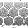
- a fluid path network 100 which comprises a multiplicity of fluid paths in the form of tubes, for brevity only some of which are given the reference 110. At each of their ends, the otherwise closed tubes open into a nodal chamber 120, which provides a fluidic link between the tubes in use.
- each nodal chamber 120 has three incoming tubes 110, except at the edges of the network where the chambers 120 have just two tubular connections 110.
- FIG. 2 shows the network features in more detail.
- Each chamber 120 is an open ended cylinder and has an axis A.
- the tubes 110 have openings 112 which open into the chambers 120.
- the tubes in this example tubes 110a, 110b and 110c, each extend radially away from the axis A in different directions, such that they form a branch, with adjacent branches having approximately a 120-degree divergence angle D.
- the network is made from a moulded plastics material, for example: HDPE; Polyamide; ABS; PEEK; or PTFE.
- tubes 110a, 110b and 110c, as well as chamber 120a are moulded as one assembly for interconnecting to adjacent assemblies in use, for example by the use of adapter collars 114.
- Figure 3a shows an insert in the form of a fluid diverting plug 130 which can be inserted into any one of the chambers 120 shown in Figure 1 and 2 .
- the plug 130 is a fluid tight fit in the chamber 120.
- the plug includes a through passage 132, which, when the plug is inserted fully into a chamber 120 and aligned correctly about axis A, can provide fluid communication between two adjacent fluid tubes 110.
- the plug 130 can also be turned such that it is misaligned and will thereby obstruct or partially obstruct fluid flow between all adjacent nodally connected tubes 110, and thereby will act like a fluid stop.
- groove 134 which corresponds to the position of the through passage 132 and can be used to guide manual alignment in use.
- Figure 3b shows a further view of the fluid diverting plug 130, sectioned through the passage 132, and better showing that the through passage 132 is curved such that aligns with the divergent branches of the tubes 110 at an angle D of about 120 degrees.
- Figure 3c shows an insert 140, in the form of a valve stem which is similar to the plug 130, in that it includes a through passage 142.
- Valve stem 140 additionally includes an irregular blind aperture 144 which is intended to mate with the rotor actuator shaft of a valve mechanism, and thereby to allow electronically or automatically controlled opening or obstruction of the tubes 110 in use.
- Figure 3d shows another insert, in the form of a fluid transfer inlet/ outlet adapter 150, in fluid communication with a fluidic unit 200, which unit is described in more detail below.
- the fluid transfer insert 150 is rotatable about axis A, such that an inlet/outlet 152 can be aligned with one of the openings 112 of the tubes 110, in use.
- the insert 150 can be modified so that it includes both an inlet and an outlet fluid path for compactness, which paths will each connect to one of the openings 112. Similar inserts can be used to connect to conventional capillary tubes, instead of the unit 200.
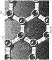
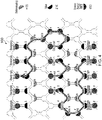
- Figure 4 shows a typical example of a chromatography fluid path, including the tubular fluid path network arranged with inserts to direct fluid, and to control the fluid flow through valve-like inserts.
- a separating column, sensor, monitor, pump or the like peripheral fluidic unit is needed, these processes can be performed outside the network by diverting fluid flow through inserts 150 described above, either directly into said unit, or via conventional capillary tubes.
- Figure 5 shows an enlarged view of a further typical fluid path routing using the inserts mentioned above, and showing how the valve stem insert 140 can divert flow.
- Figure 6a shows an array 250 of stacked chromatography units 200, which have inserts 150, or valve stem insert actuators, which are in an array, to coincide with the chambers 120 of the tubular network 100.
- the units 200 can be mated with the network 100, to provide a complete chromatography system 300 as shown in Figure 6b .
- Dummy units 210 can be used to infill any gaps in the array.
- the units 200 can be assembled in any suitable order, and the fluid path network 100 can be made both easy to configure and reconfigure, as well as being disposable should cleaning be important.
- Units 200 may comprise one or more of: a chromatography column; a pressure sensor; a conductivity monitor; a UV monitor; a pump; a fluid reservoir; or a filter a pH monitor
- the embodiments provide a two dimensional array of interconnectable fluid paths coming together at a plurality nodal chambers at which the various fluid path modifying inserts can be removeably inserted to effect fluid manipulations, for example switching flows in different directions, providing a take-off for a bio-processing module, the blanking (stopping) of fluid paths etc. collectively providing a versatile low cost fluid interconnection system system which can be readily configured or reconfigured if needed.
- the embodiments are preferably formed from rigid moulded plastics to form the array which is self-supporting and/or preferably the fluid path modifying inserts are each capable of fitting in any one of the chambers. A three dimensional array is possible also.
Landscapes
- Engineering & Computer Science (AREA)
- General Engineering & Computer Science (AREA)
- Mechanical Engineering (AREA)
- Chemical & Material Sciences (AREA)
- Health & Medical Sciences (AREA)
- Life Sciences & Earth Sciences (AREA)
- Physics & Mathematics (AREA)
- Analytical Chemistry (AREA)
- Biochemistry (AREA)
- General Health & Medical Sciences (AREA)
- General Physics & Mathematics (AREA)
- Immunology (AREA)
- Pathology (AREA)
- Treatment Of Liquids With Adsorbents In General (AREA)
- Multiple-Way Valves (AREA)
Claims (3)
- Rekonfigurierbares Fluidpfadnetzwerk, umfassend mehrere rohrförmige Fluidpfade (110), die durch mehrere Knotenkammern (120) untereinander verbunden sind, wobei die Kammern in einem Feld angeordnet sind, im Allgemeinen durch die rohrförmigen Wände der Fluidpfade in Position gehalten, drei oder mehrere der mehreren Pfade sich in jede der Kammern öffnen, und weiter umfassend eine Vielzahl von fluidpfadmodifizierenden Einsätzen (130/140/150), die angepasst sind, um in eine beliebige der Kammern zu passen, wobei die Kammern zylindrisch sind und mindestens ein, vorzugsweise zwei, offene Enden aufweisen, um die Einsätze aufzunehmen, wobei die Kammern um eine Achse gebildet sind, und die drei oder mehreren Fluidpfade sich radial von jeder Kammer weg zu einer anderen der mehreren Knotenkammern erstrecken, und wobei die mehreren fluidpfadmodifizierenden Einsätze abnehmbar in die Kammern eingesetzt sind, um die Fluidpfade zu modifizieren, wobei eine erste Gruppe der Einsätze einen um die Achse drehbaren Ventilschaft (140) umfasst, um zwei oder mehre der mindestens drei Fluidpfade selektiv untereinander zu verbinden.
- Fluidpfadnetzwerk nach Anspruch 1, wobei: eine zweite Gruppe der Einsätze einen Stopfen (130) zum Blockieren eines oder mehrerer der mindestens drei Fluidpfade, aber zwei oder mehrere der mindestens drei Fluidpfade verbindend, umfasst; und/oder eine dritte Gruppe der Einsätze (150) einen Adapter zum Transferieren von Fluid weg vom Netzwerk oder zu diesem umfasst.
- Verwendung eines rekonfigurierbaren Fluidpfadnetzwerks nach Anspruch 1 oder 2 zum Verbinden fluidischer Chromatographieeinheiten untereinander.
Applications Claiming Priority (2)
| Application Number | Priority Date | Filing Date | Title |
|---|---|---|---|
| GBGB1511463.0A GB201511463D0 (en) | 2015-06-30 | 2015-06-30 | Improvements in and relating to fluid path networks |
| PCT/EP2016/065100 WO2017001454A1 (en) | 2015-06-30 | 2016-06-29 | Improvements in and relating to fluid path networks |
Publications (2)
| Publication Number | Publication Date |
|---|---|
| EP3317660A1 EP3317660A1 (de) | 2018-05-09 |
| EP3317660B1 true EP3317660B1 (de) | 2019-07-31 |
Family
ID=53872446
Family Applications (1)
| Application Number | Title | Priority Date | Filing Date |
|---|---|---|---|
| EP16736419.9A Active EP3317660B1 (de) | 2015-06-30 | 2016-06-29 | Verbesserungen an und im zusammenhang mit fluidpfadnetzwerken |
Country Status (5)
| Country | Link |
|---|---|
| US (1) | US10670569B2 (de) |
| EP (1) | EP3317660B1 (de) |
| CN (1) | CN107820551B (de) |
| GB (1) | GB201511463D0 (de) |
| WO (1) | WO2017001454A1 (de) |
Families Citing this family (1)
| Publication number | Priority date | Publication date | Assignee | Title |
|---|---|---|---|---|
| EP4260058B1 (de) * | 2020-12-11 | 2024-11-13 | Life Technologies Corporation | Mehrsäulen-chromatografiesysteme mit drehbaren ventilanordnungen |
Family Cites Families (15)
| Publication number | Priority date | Publication date | Assignee | Title |
|---|---|---|---|---|
| US5487569A (en) | 1994-10-12 | 1996-01-30 | Restek Corporation | Connector for three or more capillary tubes |
| US6156273A (en) | 1997-05-27 | 2000-12-05 | Purdue Research Corporation | Separation columns and methods for manufacturing the improved separation columns |
| US6568428B2 (en) * | 1998-07-23 | 2003-05-27 | Laars, Inc. | Backwash valve |
| DE502004001209D1 (de) * | 2003-04-03 | 2006-09-28 | Alois Schwarz | Einrichtung zur steuerung der strömung von flüssigen oder gasförmigen medien |
| US6973979B2 (en) | 2003-04-15 | 2005-12-13 | Savanna Energy Services Corp. | Drilling rig apparatus and downhole tool assembly system and method |
| WO2004101151A1 (en) | 2003-05-08 | 2004-11-25 | Nanostream, Inc. | Sample preparation for parallel chromatography |
| US7370674B2 (en) | 2004-02-20 | 2008-05-13 | Michael Doyle | Modular fluid distribution system |
| US7146999B2 (en) * | 2005-03-08 | 2006-12-12 | Gregory C. Giese | Modular fluid handling device |
| US7320338B2 (en) * | 2005-06-03 | 2008-01-22 | Honeywell International Inc. | Microvalve package assembly |
| JP5037510B2 (ja) * | 2006-08-23 | 2012-09-26 | 株式会社堀場エステック | 集積型ガスパネル装置 |
| US7726331B1 (en) * | 2007-05-23 | 2010-06-01 | Giese Gregory C | Modular fluid handling device II |
| CN201661732U (zh) * | 2010-03-30 | 2010-12-01 | 赵书文 | 汽车气路控制整体阀座 |
| EP2633306B1 (de) | 2010-10-27 | 2016-03-23 | GE Healthcare Bio-Sciences AB | Chromatographiesystem mit sicherungssäulen |
| US9440233B2 (en) | 2013-08-09 | 2016-09-13 | Shark Kabushiki Kaisha | Microfluidic device for serial fluidic operations |
| WO2015094095A1 (en) | 2013-12-19 | 2015-06-25 | Ge Healthcare Bio-Sciences Ab | Rotary valve |
-
2015
- 2015-06-30 GB GBGB1511463.0A patent/GB201511463D0/en not_active Ceased
-
2016
- 2016-06-29 EP EP16736419.9A patent/EP3317660B1/de active Active
- 2016-06-29 CN CN201680038747.3A patent/CN107820551B/zh active Active
- 2016-06-29 US US15/738,789 patent/US10670569B2/en active Active
- 2016-06-29 WO PCT/EP2016/065100 patent/WO2017001454A1/en not_active Ceased
Non-Patent Citations (1)
| Title |
|---|
| None * |
Also Published As
| Publication number | Publication date |
|---|---|
| GB201511463D0 (en) | 2015-08-12 |
| WO2017001454A1 (en) | 2017-01-05 |
| CN107820551A (zh) | 2018-03-20 |
| EP3317660A1 (de) | 2018-05-09 |
| US10670569B2 (en) | 2020-06-02 |
| CN107820551B (zh) | 2020-10-23 |
| US20180188216A1 (en) | 2018-07-05 |
Similar Documents
| Publication | Publication Date | Title |
|---|---|---|
| JP7483298B2 (ja) | モジュール式バイオ処理ユニットおよび複数のユニットを用いるバイオ処理システム | |
| JP6702588B2 (ja) | スタック可能なクロマトグラフィーカラムモジュールおよび流れ制御ブロック | |
| JP6758660B2 (ja) | 回転バルブおよびクロマトグラフィシステム | |
| CN101946109B (zh) | 带有流动转向件的三通阀 | |
| US10260648B2 (en) | Actuating dump valve | |
| US6568428B2 (en) | Backwash valve | |
| US20030196713A1 (en) | Flow-diverting rotary valves of multiple paths | |
| US20170321813A1 (en) | Rotary Valve and Systems | |
| US20150273484A1 (en) | Modular cyclonic separator for separating solid impurities from an airflow | |
| US12623168B2 (en) | Modular device for fixedly arranging and interconnecting individual separation units and/or function units amongst one another | |
| GB2593635A8 (en) | A filter device, and method of assembly | |
| US10670569B2 (en) | Fluid path networks | |
| US10391453B2 (en) | End cap filtration module, filtration module and filtration system | |
| KR101889587B1 (ko) | 투과액 수집 피팅부 | |
| CN110573776A (zh) | 特别是用于冷却和加热设备的液压连接单元 | |
| EP1489342A1 (de) | Dreiwegeventil | |
| US20250387736A1 (en) | Modular connector and filtration device with modular connection features | |
| DK3101318T3 (en) | VALVE MODULE | |
| IT202200024810A1 (it) | Valvola distributrice ed impianto di filtrazione contenente la medesima | |
| US20060151363A1 (en) | Modular disc filter with integrated and automated self-flushing operator | |
| EP3910217A1 (de) | Vorrichtung mit konfiguration zum steuern des durchflusses z. b. in einem unterwasser-wasserverarbeitungssystem | |
| WO2018141767A1 (en) | Method for connecting at least two fluid valves and the system for fluid communication implemented | |
| AU2014100561A4 (en) | Modular cyclonic separator for separating solid impurities from an airflow | |
| CN104144881B (zh) | 净水系统 | |
| CA2847964C (en) | Modular cyclonic separator for separating solid impurities from an airflow |
Legal Events
| Date | Code | Title | Description |
|---|---|---|---|
| STAA | Information on the status of an ep patent application or granted ep patent |
Free format text: STATUS: THE INTERNATIONAL PUBLICATION HAS BEEN MADE |
|
| PUAI | Public reference made under article 153(3) epc to a published international application that has entered the european phase |
Free format text: ORIGINAL CODE: 0009012 |
|
| STAA | Information on the status of an ep patent application or granted ep patent |
Free format text: STATUS: REQUEST FOR EXAMINATION WAS MADE |
|
| 17P | Request for examination filed |
Effective date: 20171222 |
|
| AK | Designated contracting states |
Kind code of ref document: A1 Designated state(s): AL AT BE BG CH CY CZ DE DK EE ES FI FR GB GR HR HU IE IS IT LI LT LU LV MC MK MT NL NO PL PT RO RS SE SI SK SM TR |
|
| AX | Request for extension of the european patent |
Extension state: BA ME |
|
| DAV | Request for validation of the european patent (deleted) | ||
| DAX | Request for extension of the european patent (deleted) | ||
| REG | Reference to a national code |
Ref country code: DE Ref legal event code: R079 Ref document number: 602016017744 Country of ref document: DE Free format text: PREVIOUS MAIN CLASS: G01N0030380000 Ipc: F16K0011085000 |
|
| RIC1 | Information provided on ipc code assigned before grant |
Ipc: F16K 27/02 20060101ALI20181212BHEP Ipc: G01N 30/38 20060101ALI20181212BHEP Ipc: G01N 30/88 20060101ALI20181212BHEP Ipc: F16K 11/085 20060101AFI20181212BHEP Ipc: F16K 27/00 20060101ALI20181212BHEP |
|
| GRAP | Despatch of communication of intention to grant a patent |
Free format text: ORIGINAL CODE: EPIDOSNIGR1 |
|
| STAA | Information on the status of an ep patent application or granted ep patent |
Free format text: STATUS: GRANT OF PATENT IS INTENDED |
|
| INTG | Intention to grant announced |
Effective date: 20190128 |
|
| RIN1 | Information on inventor provided before grant (corrected) |
Inventor name: OLOVSSON, BJORN, MARKUS |
|
| GRAS | Grant fee paid |
Free format text: ORIGINAL CODE: EPIDOSNIGR3 |
|
| GRAA | (expected) grant |
Free format text: ORIGINAL CODE: 0009210 |
|
| STAA | Information on the status of an ep patent application or granted ep patent |
Free format text: STATUS: THE PATENT HAS BEEN GRANTED |
|
| AK | Designated contracting states |
Kind code of ref document: B1 Designated state(s): AL AT BE BG CH CY CZ DE DK EE ES FI FR GB GR HR HU IE IS IT LI LT LU LV MC MK MT NL NO PL PT RO RS SE SI SK SM TR |
|
| REG | Reference to a national code |
Ref country code: CH Ref legal event code: EP Ref country code: GB Ref legal event code: FG4D |
|
| REG | Reference to a national code |
Ref country code: AT Ref legal event code: REF Ref document number: 1161247 Country of ref document: AT Kind code of ref document: T Effective date: 20190815 |
|
| REG | Reference to a national code |
Ref country code: IE Ref legal event code: FG4D |
|
| REG | Reference to a national code |
Ref country code: DE Ref legal event code: R096 Ref document number: 602016017744 Country of ref document: DE |
|
| REG | Reference to a national code |
Ref country code: NL Ref legal event code: MP Effective date: 20190731 |
|
| REG | Reference to a national code |
Ref country code: LT Ref legal event code: MG4D |
|
| REG | Reference to a national code |
Ref country code: AT Ref legal event code: MK05 Ref document number: 1161247 Country of ref document: AT Kind code of ref document: T Effective date: 20190731 |
|
| PG25 | Lapsed in a contracting state [announced via postgrant information from national office to epo] |
Ref country code: NO Free format text: LAPSE BECAUSE OF FAILURE TO SUBMIT A TRANSLATION OF THE DESCRIPTION OR TO PAY THE FEE WITHIN THE PRESCRIBED TIME-LIMIT Effective date: 20191031 Ref country code: NL Free format text: LAPSE BECAUSE OF FAILURE TO SUBMIT A TRANSLATION OF THE DESCRIPTION OR TO PAY THE FEE WITHIN THE PRESCRIBED TIME-LIMIT Effective date: 20190731 Ref country code: AT Free format text: LAPSE BECAUSE OF FAILURE TO SUBMIT A TRANSLATION OF THE DESCRIPTION OR TO PAY THE FEE WITHIN THE PRESCRIBED TIME-LIMIT Effective date: 20190731 Ref country code: BG Free format text: LAPSE BECAUSE OF FAILURE TO SUBMIT A TRANSLATION OF THE DESCRIPTION OR TO PAY THE FEE WITHIN THE PRESCRIBED TIME-LIMIT Effective date: 20191031 Ref country code: PT Free format text: LAPSE BECAUSE OF FAILURE TO SUBMIT A TRANSLATION OF THE DESCRIPTION OR TO PAY THE FEE WITHIN THE PRESCRIBED TIME-LIMIT Effective date: 20191202 Ref country code: FI Free format text: LAPSE BECAUSE OF FAILURE TO SUBMIT A TRANSLATION OF THE DESCRIPTION OR TO PAY THE FEE WITHIN THE PRESCRIBED TIME-LIMIT Effective date: 20190731 Ref country code: LT Free format text: LAPSE BECAUSE OF FAILURE TO SUBMIT A TRANSLATION OF THE DESCRIPTION OR TO PAY THE FEE WITHIN THE PRESCRIBED TIME-LIMIT Effective date: 20190731 Ref country code: SE Free format text: LAPSE BECAUSE OF FAILURE TO SUBMIT A TRANSLATION OF THE DESCRIPTION OR TO PAY THE FEE WITHIN THE PRESCRIBED TIME-LIMIT Effective date: 20190731 Ref country code: HR Free format text: LAPSE BECAUSE OF FAILURE TO SUBMIT A TRANSLATION OF THE DESCRIPTION OR TO PAY THE FEE WITHIN THE PRESCRIBED TIME-LIMIT Effective date: 20190731 |
|
| PG25 | Lapsed in a contracting state [announced via postgrant information from national office to epo] |
Ref country code: GR Free format text: LAPSE BECAUSE OF FAILURE TO SUBMIT A TRANSLATION OF THE DESCRIPTION OR TO PAY THE FEE WITHIN THE PRESCRIBED TIME-LIMIT Effective date: 20191101 Ref country code: AL Free format text: LAPSE BECAUSE OF FAILURE TO SUBMIT A TRANSLATION OF THE DESCRIPTION OR TO PAY THE FEE WITHIN THE PRESCRIBED TIME-LIMIT Effective date: 20190731 Ref country code: LV Free format text: LAPSE BECAUSE OF FAILURE TO SUBMIT A TRANSLATION OF THE DESCRIPTION OR TO PAY THE FEE WITHIN THE PRESCRIBED TIME-LIMIT Effective date: 20190731 Ref country code: RS Free format text: LAPSE BECAUSE OF FAILURE TO SUBMIT A TRANSLATION OF THE DESCRIPTION OR TO PAY THE FEE WITHIN THE PRESCRIBED TIME-LIMIT Effective date: 20190731 Ref country code: IS Free format text: LAPSE BECAUSE OF FAILURE TO SUBMIT A TRANSLATION OF THE DESCRIPTION OR TO PAY THE FEE WITHIN THE PRESCRIBED TIME-LIMIT Effective date: 20191130 Ref country code: ES Free format text: LAPSE BECAUSE OF FAILURE TO SUBMIT A TRANSLATION OF THE DESCRIPTION OR TO PAY THE FEE WITHIN THE PRESCRIBED TIME-LIMIT Effective date: 20190731 |
|
| PG25 | Lapsed in a contracting state [announced via postgrant information from national office to epo] |
Ref country code: TR Free format text: LAPSE BECAUSE OF FAILURE TO SUBMIT A TRANSLATION OF THE DESCRIPTION OR TO PAY THE FEE WITHIN THE PRESCRIBED TIME-LIMIT Effective date: 20190731 |
|
| PG25 | Lapsed in a contracting state [announced via postgrant information from national office to epo] |
Ref country code: IT Free format text: LAPSE BECAUSE OF FAILURE TO SUBMIT A TRANSLATION OF THE DESCRIPTION OR TO PAY THE FEE WITHIN THE PRESCRIBED TIME-LIMIT Effective date: 20190731 Ref country code: PL Free format text: LAPSE BECAUSE OF FAILURE TO SUBMIT A TRANSLATION OF THE DESCRIPTION OR TO PAY THE FEE WITHIN THE PRESCRIBED TIME-LIMIT Effective date: 20190731 Ref country code: DK Free format text: LAPSE BECAUSE OF FAILURE TO SUBMIT A TRANSLATION OF THE DESCRIPTION OR TO PAY THE FEE WITHIN THE PRESCRIBED TIME-LIMIT Effective date: 20190731 Ref country code: EE Free format text: LAPSE BECAUSE OF FAILURE TO SUBMIT A TRANSLATION OF THE DESCRIPTION OR TO PAY THE FEE WITHIN THE PRESCRIBED TIME-LIMIT Effective date: 20190731 Ref country code: RO Free format text: LAPSE BECAUSE OF FAILURE TO SUBMIT A TRANSLATION OF THE DESCRIPTION OR TO PAY THE FEE WITHIN THE PRESCRIBED TIME-LIMIT Effective date: 20190731 |
|
| PG25 | Lapsed in a contracting state [announced via postgrant information from national office to epo] |
Ref country code: IS Free format text: LAPSE BECAUSE OF FAILURE TO SUBMIT A TRANSLATION OF THE DESCRIPTION OR TO PAY THE FEE WITHIN THE PRESCRIBED TIME-LIMIT Effective date: 20200224 Ref country code: CZ Free format text: LAPSE BECAUSE OF FAILURE TO SUBMIT A TRANSLATION OF THE DESCRIPTION OR TO PAY THE FEE WITHIN THE PRESCRIBED TIME-LIMIT Effective date: 20190731 Ref country code: SM Free format text: LAPSE BECAUSE OF FAILURE TO SUBMIT A TRANSLATION OF THE DESCRIPTION OR TO PAY THE FEE WITHIN THE PRESCRIBED TIME-LIMIT Effective date: 20190731 Ref country code: SK Free format text: LAPSE BECAUSE OF FAILURE TO SUBMIT A TRANSLATION OF THE DESCRIPTION OR TO PAY THE FEE WITHIN THE PRESCRIBED TIME-LIMIT Effective date: 20190731 |
|
| REG | Reference to a national code |
Ref country code: DE Ref legal event code: R097 Ref document number: 602016017744 Country of ref document: DE |
|
| PLBE | No opposition filed within time limit |
Free format text: ORIGINAL CODE: 0009261 |
|
| STAA | Information on the status of an ep patent application or granted ep patent |
Free format text: STATUS: NO OPPOSITION FILED WITHIN TIME LIMIT |
|
| PG2D | Information on lapse in contracting state deleted |
Ref country code: IS |
|
| PG25 | Lapsed in a contracting state [announced via postgrant information from national office to epo] |
Ref country code: IS Free format text: LAPSE BECAUSE OF FAILURE TO SUBMIT A TRANSLATION OF THE DESCRIPTION OR TO PAY THE FEE WITHIN THE PRESCRIBED TIME-LIMIT Effective date: 20191030 |
|
| 26N | No opposition filed |
Effective date: 20200603 |
|
| PG25 | Lapsed in a contracting state [announced via postgrant information from national office to epo] |
Ref country code: SI Free format text: LAPSE BECAUSE OF FAILURE TO SUBMIT A TRANSLATION OF THE DESCRIPTION OR TO PAY THE FEE WITHIN THE PRESCRIBED TIME-LIMIT Effective date: 20190731 |
|
| REG | Reference to a national code |
Ref country code: DE Ref legal event code: R081 Ref document number: 602016017744 Country of ref document: DE Owner name: CYTIVA SWEDEN AB, SE Free format text: FORMER OWNER: GE HEALTHCARE BIO-SCIENCES AB, UPPSALA, SE |
|
| PG25 | Lapsed in a contracting state [announced via postgrant information from national office to epo] |
Ref country code: MC Free format text: LAPSE BECAUSE OF FAILURE TO SUBMIT A TRANSLATION OF THE DESCRIPTION OR TO PAY THE FEE WITHIN THE PRESCRIBED TIME-LIMIT Effective date: 20190731 |
|
| REG | Reference to a national code |
Ref country code: CH Ref legal event code: PL |
|
| PG25 | Lapsed in a contracting state [announced via postgrant information from national office to epo] |
Ref country code: LU Free format text: LAPSE BECAUSE OF NON-PAYMENT OF DUE FEES Effective date: 20200629 |
|
| REG | Reference to a national code |
Ref country code: BE Ref legal event code: MM Effective date: 20200630 |
|
| PG25 | Lapsed in a contracting state [announced via postgrant information from national office to epo] |
Ref country code: IE Free format text: LAPSE BECAUSE OF NON-PAYMENT OF DUE FEES Effective date: 20200629 Ref country code: CH Free format text: LAPSE BECAUSE OF NON-PAYMENT OF DUE FEES Effective date: 20200630 Ref country code: LI Free format text: LAPSE BECAUSE OF NON-PAYMENT OF DUE FEES Effective date: 20200630 |
|
| PG25 | Lapsed in a contracting state [announced via postgrant information from national office to epo] |
Ref country code: BE Free format text: LAPSE BECAUSE OF NON-PAYMENT OF DUE FEES Effective date: 20200630 |
|
| PG25 | Lapsed in a contracting state [announced via postgrant information from national office to epo] |
Ref country code: MT Free format text: LAPSE BECAUSE OF FAILURE TO SUBMIT A TRANSLATION OF THE DESCRIPTION OR TO PAY THE FEE WITHIN THE PRESCRIBED TIME-LIMIT Effective date: 20190731 Ref country code: CY Free format text: LAPSE BECAUSE OF FAILURE TO SUBMIT A TRANSLATION OF THE DESCRIPTION OR TO PAY THE FEE WITHIN THE PRESCRIBED TIME-LIMIT Effective date: 20190731 |
|
| PG25 | Lapsed in a contracting state [announced via postgrant information from national office to epo] |
Ref country code: MK Free format text: LAPSE BECAUSE OF FAILURE TO SUBMIT A TRANSLATION OF THE DESCRIPTION OR TO PAY THE FEE WITHIN THE PRESCRIBED TIME-LIMIT Effective date: 20190731 |
|
| P01 | Opt-out of the competence of the unified patent court (upc) registered |
Effective date: 20230526 |
|
| PGFP | Annual fee paid to national office [announced via postgrant information from national office to epo] |
Ref country code: GB Payment date: 20260622 Year of fee payment: 11 |
|
| PGFP | Annual fee paid to national office [announced via postgrant information from national office to epo] |
Ref country code: DE Payment date: 20260623 Year of fee payment: 11 |
|
| PGFP | Annual fee paid to national office [announced via postgrant information from national office to epo] |
Ref country code: FR Payment date: 20260622 Year of fee payment: 11 |