EP3317855B1 - Procédé et appareil d'analyse d'une surface d'un pneu - Google Patents
Procédé et appareil d'analyse d'une surface d'un pneu Download PDFInfo
- Publication number
- EP3317855B1 EP3317855B1 EP16751337.3A EP16751337A EP3317855B1 EP 3317855 B1 EP3317855 B1 EP 3317855B1 EP 16751337 A EP16751337 A EP 16751337A EP 3317855 B1 EP3317855 B1 EP 3317855B1
- Authority
- EP
- European Patent Office
- Prior art keywords
- image
- region
- pixel
- model
- pattern
- Prior art date
- Legal status (The legal status is an assumption and is not a legal conclusion. Google has not performed a legal analysis and makes no representation as to the accuracy of the status listed.)
- Active
Links
Images








Classifications
-
- G—PHYSICS
- G01—MEASURING; TESTING
- G01M—TESTING STATIC OR DYNAMIC BALANCE OF MACHINES OR STRUCTURES; TESTING OF STRUCTURES OR APPARATUS, NOT OTHERWISE PROVIDED FOR
- G01M17/00—Testing of vehicles
- G01M17/007—Wheeled or endless-tracked vehicles
- G01M17/02—Tyres
- G01M17/027—Tyres using light, e.g. infrared, ultraviolet or holographic techniques
-
- G—PHYSICS
- G01—MEASURING; TESTING
- G01N—INVESTIGATING OR ANALYSING MATERIALS BY DETERMINING THEIR CHEMICAL OR PHYSICAL PROPERTIES
- G01N21/00—Investigating or analysing materials by the use of optical means, i.e. using sub-millimetre waves, infrared, visible or ultraviolet light
- G01N21/84—Systems specially adapted for particular applications
- G01N21/88—Investigating the presence of flaws or contamination
- G01N21/8851—Scan or image signal processing specially adapted therefor, e.g. for scan signal adjustment, for detecting different kinds of defects, for compensating for structures, markings, edges
-
- G—PHYSICS
- G06—COMPUTING OR CALCULATING; COUNTING
- G06T—IMAGE DATA PROCESSING OR GENERATION, IN GENERAL
- G06T7/00—Image analysis
-
- G—PHYSICS
- G06—COMPUTING OR CALCULATING; COUNTING
- G06T—IMAGE DATA PROCESSING OR GENERATION, IN GENERAL
- G06T7/00—Image analysis
- G06T7/0002—Inspection of images, e.g. flaw detection
- G06T7/0004—Industrial image inspection
- G06T7/001—Industrial image inspection using an image reference approach
-
- G—PHYSICS
- G01—MEASURING; TESTING
- G01N—INVESTIGATING OR ANALYSING MATERIALS BY DETERMINING THEIR CHEMICAL OR PHYSICAL PROPERTIES
- G01N21/00—Investigating or analysing materials by the use of optical means, i.e. using sub-millimetre waves, infrared, visible or ultraviolet light
- G01N21/84—Systems specially adapted for particular applications
- G01N21/88—Investigating the presence of flaws or contamination
- G01N21/8851—Scan or image signal processing specially adapted therefor, e.g. for scan signal adjustment, for detecting different kinds of defects, for compensating for structures, markings, edges
- G01N2021/8887—Scan or image signal processing specially adapted therefor, e.g. for scan signal adjustment, for detecting different kinds of defects, for compensating for structures, markings, edges based on image processing techniques
-
- G—PHYSICS
- G01—MEASURING; TESTING
- G01N—INVESTIGATING OR ANALYSING MATERIALS BY DETERMINING THEIR CHEMICAL OR PHYSICAL PROPERTIES
- G01N21/00—Investigating or analysing materials by the use of optical means, i.e. using sub-millimetre waves, infrared, visible or ultraviolet light
- G01N21/84—Systems specially adapted for particular applications
- G01N21/88—Investigating the presence of flaws or contamination
- G01N21/95—Investigating the presence of flaws or contamination characterised by the material or shape of the object to be examined
- G01N21/952—Inspecting the exterior surface of cylindrical bodies or wires
-
- G—PHYSICS
- G01—MEASURING; TESTING
- G01N—INVESTIGATING OR ANALYSING MATERIALS BY DETERMINING THEIR CHEMICAL OR PHYSICAL PROPERTIES
- G01N21/00—Investigating or analysing materials by the use of optical means, i.e. using sub-millimetre waves, infrared, visible or ultraviolet light
- G01N21/84—Systems specially adapted for particular applications
- G01N21/88—Investigating the presence of flaws or contamination
- G01N21/95—Investigating the presence of flaws or contamination characterised by the material or shape of the object to be examined
- G01N21/956—Inspecting patterns on the surface of objects
- G01N21/95607—Inspecting patterns on the surface of objects using a comparative method
-
- G—PHYSICS
- G06—COMPUTING OR CALCULATING; COUNTING
- G06T—IMAGE DATA PROCESSING OR GENERATION, IN GENERAL
- G06T2207/00—Indexing scheme for image analysis or image enhancement
- G06T2207/10—Image acquisition modality
- G06T2207/10141—Special mode during image acquisition
- G06T2207/10152—Varying illumination
-
- G—PHYSICS
- G06—COMPUTING OR CALCULATING; COUNTING
- G06T—IMAGE DATA PROCESSING OR GENERATION, IN GENERAL
- G06T2207/00—Indexing scheme for image analysis or image enhancement
- G06T2207/20—Special algorithmic details
- G06T2207/20036—Morphological image processing
-
- G—PHYSICS
- G06—COMPUTING OR CALCULATING; COUNTING
- G06T—IMAGE DATA PROCESSING OR GENERATION, IN GENERAL
- G06T2207/00—Indexing scheme for image analysis or image enhancement
- G06T2207/20—Special algorithmic details
- G06T2207/20212—Image combination
- G06T2207/20216—Image averaging
-
- G—PHYSICS
- G06—COMPUTING OR CALCULATING; COUNTING
- G06T—IMAGE DATA PROCESSING OR GENERATION, IN GENERAL
- G06T2207/00—Indexing scheme for image analysis or image enhancement
- G06T2207/20—Special algorithmic details
- G06T2207/20212—Image combination
- G06T2207/20224—Image subtraction
Definitions
- the present invention relates to a method and an apparatus for analysing a surface of a tyre, for example for detecting the possible presence of defects on the tyre surface.
- 'defect' it is meant any deviation from a desired condition, irrespective of the fact that such deviation gives rise to a degradation of the performance of the tyre (which can thus be discarded or downgraded) or consists of a simple anomaly (e.g. aesthetic) that does not cause the tyre to be discarded or downgraded.
- the defects may for example be portions with non-vulcanised compound, alterations in shape, cuts, creeps in the carcass, presence of foreign bodies on the surface, etc.
- tyre it is meant the finished tyre, that is, after the moulding and vulcanisation steps.
- a moulding and vulcanisation treatment is typically carried out in order to determine the structural stabilisation of the tyre through cross-linking of the elastomeric compositions as well as to impart a desired tread pattern thereon and any distinguishing or information graphic signs at the sidewalls.
- a suitable bladder (typically of an elastomeric compound) is inserted inside the tyre and made to expand (e.g. pneumatically) against the inner surface of the same, in order to push the tyre against the outer mould and ensure the proper adhesion thereof to the same.
- This bladder is typically externally grooved with a pattern of grooves in order to facilitate the local mutual sliding thereof between the inner surface of the tyre and the outer surface of the bladder during vulcanisation and moulding.
- Such a pattern can facilitate the outflow of air trapped between the bladder and the tyre and/or facilitate the detachment between the bladder and the tyre at the end of the moulding and vulcanisation.
- the inner surface of the tyre has a corresponding "pattern", typically in relief.
- the pattern comprises a series of rectilinear and parallel spans typically distributed with substantial periodicity along the circumferential direction, and/or a dense network of contiguous geometric shapes (in the jargon called 'pebble edge').
- 'pattern' it is more generally meant a set of linear elements arranged on the inner or outer surface of a tyre, such linear elements being generated during the moulding and vulcanisation step of the tyre and being typically in relief, but being able to also be in low relief or simply two-dimensional, i.e. at the same elevation level as the rest of the surface.
- the tread grooves fall within the definition of pattern.
- Such surface linear elements are typically rectilinear segments interconnected in a continuous network, but can more generally have any shape and/or surface distribution. Such surface linear elements typically cause a colour change and/or reflectivity/diffusivity of an incident light compared to the rest of the surface.
- a tyre for vehicle wheels has a substantially toroidal structure around an axis of symmetry coinciding with the axis of rotation of the same during operation, and has an axial middle line plane orthogonal to the axis of symmetry, said plane typically being a geometrical (substantial) symmetry plane (ignoring any minor asymmetries, such as tread pattern and/or parts of the inner structure).
- inner surface of the tyre it is meant the surface extending inside said toroidal structure from one to the other bead (in other words, the surface no longer visible after the coupling of the tyre with the respective mounting rim).
- the inner surface typically belongs to a layer of elastomeric material, usually called "liner", having optimal air impermeability characteristics. Certain defects on the inner surface, such as cuts, open joints, creeps, etc., may impair the air impermeability of the tyre.
- quality inspections include for example those performed by human operators who dedicate a fixed time to a visual and tactile inspection of the tyre; if, in the light of his own experience and sensitivity, the operator were to suspect that the tyre does not meet certain quality standards, the same tyre is subjected to further inspections, through a more detailed human inspection and/or suitable equipment in order to deepen the evaluation of any structural and/or qualitative deficiencies.
- Document WO2013/045594A1 describes a quick method of analysis of the elements in relief on the inner surface of a tyre, comprising the steps of: capturing a three-dimensional image of the surface assigning a grey level value to each pixel of the image proportional to the topographical elevation of that point to obtain a starting image, transforming the captured image in an orthogonal reference system (OXY) in which the abscissa axis (OX) represents the circumferential values, and the ordinate axis (OY) the radial values, assigning a value of the altitude gradient (f(p)) to each pixel on the surface, comparing its elevation with the elevation of a discrete and small number of points arranged on a straight line passing through the respective pixels (p) and oriented in the circumferential direction.
- OFY orthogonal reference system
- US 2011/0013823 A1 discloses a method for evaluating the surfaces of a tire wherein a collection of N images of a given zone of the tire is constituted based on the images originating from one or more tires and then the images of said collection are made to correspond by superposition, and the image of the zone of a tire from said collection to be evaluated is compared with a reference image.
- US2011/0075937 A1 discloses a pattern detection apparatus which inputs an image of an object including repetitive patterns, estimates a period of the repetitive patterns in the input object, and generates a reference image based on images divided by the estimated period. Then, the pattern detection apparatus compares the reference image and the image of the object, and detects the positions of individual patterns in the repetitive patterns based on the comparison result.
- the Applicant has set itself the problem of detecting the possible presence of defects on the surface of a tyre by the optical acquisition of digital images and subsequent processing thereof.
- the Applicant has observed for the quality control to be used "in line" in a plant for the production of tyres, it is necessary that the inspections itself is performed in a reduced time and with reduced costs.
- the computational requirement of the processing algorithms plays a crucial role, since when it is excessive, the control times increase unacceptably and/or the computational capacity required makes the control unfeasible.
- digital image or equivalently “image” it is generally meant a set of data, typically contained in a computer file, in which each tuple of coordinates (typically each pair of coordinates) of a finite set (typically two-dimensional and matrix, i.e. N rows x M columns) of tuples of spatial coordinates (each tuple corresponding to a pixel) is associated with a corresponding set of numerical values (which may be representative of different magnitudes).
- a set of values consists of a single value in a finite scale (typically 256 levels or tones), this value for example being representative of the luminosity (or intensity) level of the respective tuple of spatial coordinates when displayed.
- a further example is represented by colour images, in which the set of values represents the luminosity level of a plurality of colours or channels, typically the primary colours (for example red, green and blue in RGB coding and cyan, magenta, yellow and black in CMYK coding).
- the term 'image' does not necessarily imply the actual display of the same.
- the term 'image' encompasses both the three-dimensional images, in which each pixel is associated with a surface altitude information (such as the images obtained with laser triangulation), and two-dimensional images, in which each pixel is associated with information representative of the colour and/or reflectivity/diffusivity of the respective point of the surface, such as the images detected by the common digital cameras or video cameras (e.g. CCD).
- a surface altitude information such as the images obtained with laser triangulation
- information representative of the colour and/or reflectivity/diffusivity of the respective point of the surface such as the images detected by the common digital cameras or video cameras (e.g. CCD).
- 'point of the surface it is meant a surface portion having a small (not zero) extension compatible with the size of a pixel of an acquired image of the surface.
- any reference to a specific "digital image" includes more generally any digital image obtainable through one or more digital processing of said specific digital image (such as, for example, filtering, equalization, smoothing, binarisation, thresholding, morphological transformations (opening, etc.), derivative or integral calculations, etc.).
- the Applicant has noted that the presence of the pattern on the tyre surface disturbs the image and/or its processing, since it tends to hide or mask the defects.
- the anomalies on the pattern which per se may be such as to not justify a discard of the tyre, may however be indicative of further defects in the production process steps (such as a lack of adherence between the bladder and tyre, resulting in incomplete vulcanisation). Therefore, the Applicant considers detecting any anomalies of the pattern itself advantageous.
- the Applicant considers it advantageous to have a reference model of a pattern arranged on a surface of a tyre and free of defects, for example to be able to compare the actual pattern with the model in order to detect any real deviations from that model, or to be able to distinguish any defects from the pattern itself.
- the Applicant has also perceived the practical difficulty, if not impossibility, of having a predetermined model valid for a number of tyres to be analysed serving as a reference for the defect-free pattern, since bladders typically vary according to the manufacturer and even according to the model, and in addition, they are subjected to ageing and/or are replaced frequently. Moreover, also possible macro variations in the lighting in the image acquisition step and/or in the reflective response of the tyre surface may make the use of a predetermined model of the defect-free pattern unfeasible.
- the Applicant in the context of quality control of tyres (in particular for the detection of defects on the inner surface of tyres) based on the acquisition and processing of digital images in an industrial tyre production line, with reduced computational costs and requirements, reliable in the result obtained and also with a high degree of sensitivity in the detection of defects, in particular being capable of detecting surface defects even in the presence of a surface pattern, including defects of the pattern itself, has therefore considered the problem of developing a method of analysing the surface of tyres capable of extracting, for each tyre under analysis, a respective defect-free pattern model, at least when the pattern consists of a predetermined scheme that is repeated, substantially equal thereto, a plurality of times.
- the invention relates to a method for analysing a surface of a tyre as defined in appended claim 1.
- 'average value' it is meant any descriptive value of a central tendency of the respective statistical distribution.
- the average value for example comprises any analytical mean (which satisfies a condition of invariance) and any position mean, or combinations thereof.
- analytical mean are arithmetic mean, geometric mean, harmonic mean, quadratic mean, cubic mean, etc.
- position mean are mode and median.
- the above method in particular by the identification of the respective homologous regions and to the calculation of an average value of the values associated with the pixels of each first region and of the respective homologous regions having the same relative coordinates, is able to create a pattern model where the value associated with each pixel is calculated with a reduced or null contribution of any defects.
- a defect typically if a defect occurs it is present in only one or at most few homologous regions, all other homologous regions having the substantially 'correct' scheme, i.e. free of defects (and at most having a variance given by slight distortions).
- the defect typically generates an alteration - even significant - of the corresponding value in all pixels affected by the defect only in the homologous region affected by the defect, compared with the value of the corresponding pixels of the other defect-free regions.
- the defect contribution is diluted, the value of the other pixel samples prevailing. Therefore, compared with a moderate computational request, the above method allows auto-learning from each tyre (i.e. deriving from the acquired image and/or further processing thereof, without the need of reference images or models of the pattern) an ideal pattern model (or portions thereof), i.e. free of defects, for example for a subsequent comparison between the acquired image (and/or subsequent processing thereof) and the model (and/or subsequent processing thereof).
- said plurality of first regions forms a connected portion of said one or more digital images comprising at least said scheme.
- said connected region extends less than two times said scheme. In this way, a model of the entire pattern is calculated with a limited computational request.
- said first regions are partially overlapped on each other in an axial direction and/or in a circumferential direction of the tyre. In this way, a certain degree of information redundancy is introduced in the reconstruction of the model at the edges of the regions.
- each plurality of homologous regions includes all the regions of said one or more images having a respective scheme sub-portion substantially identical to said scheme sub-portion of the respective first region. In this way, the calculation of the model counts all the contributions available in the starting image.
- identifying said respective plurality of homologous regions comprises calculating a correlation function between said respective first region and (at least one portion of) a remaining part of said one or more digital images. In this way, the computational request is limited.
- identifying said respective plurality of homologous regions comprises identifying one (at least local) extremum of said correlation function. In this way, the regions most similar to each other are effectively identified.
- said surface portion is selected such that in said one or more digital image, said scheme is repeated substantially equal thereto at least eight times, more preferably at least ten times.
- said calculated scheme model is sufficiently robust and reliable.
- the scheme is repeated substantially equal thereto in a plurality of positions distributed along a circumferential direction of the tyre, and said respective plurality of homologous regions are distributed along the circumferential direction.
- the scheme is repeated substantially equal thereto along a direction of periodicity (typically the circumferential direction) with a substantially constant period, more preferably with continuity.
- a direction of periodicity typically the circumferential direction
- the inner surface typically has a pattern of relief (or low-relief) elements according to a scheme that is repeated with substantial periodicity and continuity (i.e. without intervals devoid of pattern) along said direction of periodicity (usually circumferential).
- a value representative of said period it is contemplated to acquire a value representative of said period, more preferably it is contemplated to derive a value representative of said period by processing said one or more digital image, even more preferably by seeking a maximum of a correlation function between a portion of said one or more digital images and a plurality of further portions of said one or more digital images having dimensions equal to the dimensions of said portion of said one or more digital images, and distributed along a direction of periodicity (usually circumferential).
- said portion of said one or more digital images develops by a length, along said direction of periodicity, greater than or equal to an overall length of the scheme and less than or equal to three times said overall length of the scheme.
- identifying said respective plurality of homologous regions comprises identifying a respective first homologous region by calculating said correlation function between said each first region and a plurality of regions having size equal to said each first region and arranged around a point of said one or more digital images located along said periodicity direction at a distance from said each first region equal to an integer multiple of said period, more preferably equal to said period.
- identifying said respective plurality of homologous regions comprises identifying a respective homologous region using said each first region (for example for the n-th respective homologous region by calculating said correlation function between said each first region and a plurality of regions having size equal to said each first region and arranged around a point of said one or more digital images located along said periodicity direction at a distance from said each first region equal to n times said period).
- identifying said respective plurality of homologous regions comprises identifying a sequence of respective homologous regions in succession, each respective homologous region of said sequence being identified by using the respective preceding homologous region in the sequence (more preferably the immediately preceding respective homologous region). This advantageously takes into account the propagation of the deformations (e.g. the non-periodicity and/or said displacements along said direction of periodicity).
- said average value comprises, or consists of, the arithmetic and/or geometric and/or quadratic mean, and/or the mode, and/or combinations thereof, of said values.
- said average value comprises, or consists of, the median value of said values.
- acquiring one or more digital images includes acquiring a first image in which each pixel is associated with a luminosity value representative of the reflectivity and/or diffusivity and/or colour of a point on the surface corresponding to said each pixel.
- the point on the surface is illuminated with diffused light.
- the meaning of the term 'luminosity value' denotes the 2D nature of the image, i.e. the nature of a normal photography the acquisition of which is simple and fast.
- the present invention is also applied to 3D images.
- said operation of obtaining a value representative of the period and/or said operation of identifying a plurality of first regions and a respective plurality of homologous regions is/are carried out in said first image and by processing said first image (e.g. said correlation functions are calculated on the luminosity values associated with the pixels, or processing thereof).
- acquiring one or more digital images includes acquiring a second and a third image in which each pixel is associated with a luminosity value representative of the reflectivity and/or diffusivity and/or colour of a point of the surface corresponding to said each pixel, said point of the surface being illuminated with grazing light (for example forming an acute angle greater than 40°, more preferably greater than 55°, with the normal to the surface at said point), more preferably coming from opposite directions, respectively.
- grazing light for example forming an acute angle greater than 40°, more preferably greater than 55°, with the normal to the surface at said point
- acquiring one or more digital images includes calculating a difference image in which each pixel is associated with a value representative of the difference of the corresponding luminosity values of said second and third image.
- the operation of obtaining a value representative of said period and/or the operation of identifying a plurality of first regions and a respective plurality of homologous regions is/are carried out at least in said difference image, by processing said difference image.
- the Applicant has in fact discovered, after repeated tests, that the self-learning of the period and/or the identification of the homologous regions by processing the difference image of images acquired in grazing light (in particular through the calculation of said correlation function in the difference image) may be more robust with respect to a corresponding processing of the image acquired in diffuse light.
- this is due to the fact that, by making the difference between the two images in grazing light, on the one hand the elements of the pattern/scheme that are in relief are emphasized, on the other hand any two-dimensional elements (such as spots, etc.) that are not part of the pattern/scheme are reduced (even up to their disappearance).
- identifying each of said first regions and said respective plurality of homologous regions comprises identifying, by means of processing said difference image, a respective position of said each first region and of said respective homologous regions in said difference image and subsequently identifying, in said first image, a corresponding first region and a corresponding respective plurality of homologous regions having said respective positions.
- said operation of calculating said model of said respective scheme sub-portion is carried out on said first image.
- the Applicant has in fact verified that the construction of the model on the image in diffuse light makes the same model easily comparable with the image in diffuse light, for example for the detection of defects.
- each pixel of at least one image among said one or more digital images it is contemplated to calculate a gradient of said values associated with the pixels along two coordinates (typically mutually orthogonal) of said image.
- the term 'gradient' in the present application is used in a general sense to indicate the variation of the values associated with the pixels along two coordinates, and not necessarily with reference to the differential calculation.
- said gradient is a vector with two components representative of a variation of said values along said two coordinates, respectively.
- each pixel is associated with a gradient modulus value (e.g. representative of the quadratic sum of said two components), and a gradient orientation value (e.g. representative of the angle formed by said vector with respect to a reference direction).
- the orientation is normalized in the range [0-180°] or [-90° - +90°].
- one or more from among said operations of identifying said plurality of first regions, identifying said respective plurality of homologous regions, calculating said model of respective scheme sub-portion and calculating said pattern model are carried out by being based on said gradient modulus values (e.g. said values associated with the pixels are the gradient modulus values and said correlation functions and/or said average value are calculated on said gradient modulus values).
- one or more from among said operations of identifying said plurality of first regions, identifying said respective plurality of homologous regions, calculating said model of respective scheme sub-portion and calculating said pattern model are carried out on said gradient orientation values (e.g. said values associated with the pixels are the orientation modulus values and said correlation functions and/or said average value are calculated on said orientation modulus values).
- said Applicant has in fact verified that the above method provides reliable results when using the gradient modulus and/or orientation values.
- a pattern model is obtained as a result in which each pixel is associated with the gradient modulus and/or orientation values.
- each pixel of the pattern model (in luminosity values) calculated on said first image provision is made for calculating a gradient modulus value and a gradient orientation value of luminosity values. Also in this way, a pattern model is obtained in which each pixel is associated with the gradient modulus and/or orientation values, similar to the method in the previous paragraph.
- any reference to a digital image is understood to include, if not specified, such image in luminosity values and/or in gradient modulus values and/or in gradient orientation values calculated on the luminosity values.
- said pattern model is obtained by substituting, in at least one image from among said one or more images (more preferably in said first image), each first region and the respective homologous regions with said model of respective scheme sub-portion.
- said pattern model is obtained by substituting, in at least one image from among said one or more images (more preferably in said first image), each first region and the respective homologous regions with said model of respective scheme sub-portion.
- a complete pattern model without defects is obtained, which can be superimposed to the entire real pattern in said one or more images.
- such pattern model can be a global model image of the surface portion comparable with said at least one of said one or more digital images, and containing a complete model of the surface portion without defects which can be superimposed to said one or more images.
- said one or more digital images (more preferably the first digital image), with said pattern model and, based on such comparison, detecting possible defects in said one or more digital images.
- a dilated pattern model by means of a dilation operation conducted on the pattern model, more preferably based on said modulus gradient values of the pattern model in luminosity values.
- variations/defects/drifts in the real pattern scheme are taken into account with a certain degree of tolerance in the comparison with the starting image.
- said dilation comprises assigning, to each pixel of the dilated pattern model, the maximum value of the gradient modulus value calculated in a predetermined area around the corresponding pixel in said pattern model (said area preferably having a radius of between 3 and 10 pixels).
- the pattern model is processed, before or after said dilation, on the basis of said gradient modulus value, so as to obtain a binary model (preferably dilated) of pattern wherein each pixel is associated with a first index (preferably binary) whose value is representative of whether the pixel belongs to the pattern (preferably dilated) or not.
- a binary model preferably dilated
- the binarisation on the gradient modulus is more robust and/or less noisy than, for example, a binarisation on the luminosity values.
- a binary model (dilated) of the pattern is obtained which is easily comparable with the starting image, for example to decide whether a certain pixel of the latter belongs or not to the pattern, possibly in case of dilated model, also taking into account the tolerances inherent in possible deformations of the pattern.
- each pixel of said dilated binary model of pattern belonging to a dilated pattern is associated with a second index, the value of which is representative of an at least local orientation of a dilated pattern section passing by said pixel.
- a pattern model is provided which also allows a comparison between the orientations of the model pattern sections and the orientations of the sections (of the pattern or potential defects) present on the acquired image.
- the value of said second index is selected on the basis of (for example equal to) the gradient orientation value of the pixel with maximum value of the gradient modulus value in a predetermined neighbourhood of said each pixel in said pattern model.
- a dilation of the gradient orientation in the model is conducted, which favours the high-modulus pixels in the gradient, which is typically a condition of the pixels belonging to the pattern sections, and excludes the low-modulus pixels of the gradient, which are less significant.
- said surface portion is a circumferential portion of inner surface, more preferably corresponding to an angle in the centre that is greater than or equal to 30°, more preferably greater than or equal to 60°, typically equal to at least one round angle.
- said circumferential inner surface portion has a width in a plane passing by said axis, greater than or equal to 50 mm, more preferably greater than or equal to 80 mm, and/or smaller than or equal to 200 mm, more preferably smaller than or equal to 150 mm.
- the method is repeated by varying each time said circumferential inner surface portion so that all the surface portions make up at least one whole inner surface half-portion that extends from the median plane to a bead.
- the method comprises carrying out the analysis described above while keeping the tyre resting on one of the sidewalls.
- the method comprises tilting the tyre so as to rest it on an opposite sidewall and repeating the operations described above.
- the invention relates to an apparatus for analysing tyres in a tyre production line as defined in appended claim 14.
- the detection system comprises a linear camera having an objective line lying on an optical plane passing by the linear camera.
- said at least one source includes a first light source, a second light source and a third light source adapted to emit a first, a second and a third light radiation, respectively, for illuminating said surface portion, more preferably a linear surface portion coincident with or near the objective line.
- said first light source and second light source lie on opposite sides, respectively, with respect to said optical plane.
- each of said first and second light source is adapted to illuminate said objective line with a respective grazing light
- said third light source is adapted to illuminate said objective line with diffuse light
- the detection system comprises a mirror having a reflective surface arranged at the third light source perpendicular to the optical plane and intersecting the latter (typically on the median line of the mirror) in a manner so as to reflect said objective line in the optical plane by an angle greater than or equal to 30° or smaller than or equal to 135°.
- the apparatus comprises a command and control unit configured for:
- the apparatus includes a movement member adapted to rotate said support, about an axis of rotation thereof, the command and control unit being configured for controlling said movement member.
- reference numeral 1 generally indicates an apparatus for analysing a surface of tyres in a tyre production line according to the present invention.
- Apparatus 1 comprises a support 102 adapted to support tyre 200 on a sidewall and to rotate the same about an axis of rotation 201 coinciding with the axis of rotation of the tyre and typically arranged according to the vertical.
- Support 102 is typically operated by a driving member, not further described and shown, since it may exemplarily be of known type.
- Apparatus 1 comprises a source 104 adapted to emit at least one light radiation for illuminating a surface portion of the tyre set on the support, and, at a distance from said source, a detection system 105 adapted to detect an optical intensity of the light radiation reflected and/or diffused by the surface portion.
- the detection system 105 comprises a camera, preferably linear and having an objective line 106 lying on an optical plane 107 passing by the linear camera and the axis of rotation 201.
- Source 104 comprises a first light source 108, a second light source 109 and a third light source 110 adapted to emit a first, a second and a third light radiation, respectively, for illuminating a linear surface portion 211 of said tyre coinciding with the objective line (for example, when the surface portion is planar) or in the vicinity of the objective line (due to the curvilinear trend of the tyre surface).
- the detection system 105 is adapted to acquire a respective two-dimensional digital image of the linear surface portion of the surface illuminated by at least one of the first, second and third light radiation.
- the apparatus comprises a robotic arm (not shown) on which the first, second and third light source and the detection system are mounted.
- the first light source 108 and the second light source 109 consist each of a single respective sub-source 111 and 112.
- the third light source 110 consists of four respective sub-sources 113 distributed on both sides of the optical plane 107 and symmetrically with respect to such plane.
- Each sub-source 111-113 has a respective main direction of development which develops parallel to the optical plane 107 and thus to the objective line 106.
- Each sub-source typically comprises a plurality of LED light sources arranged aligned along the main direction of development.
- the light sub-sources are schematically shown with reference to their respective emitting surface (exemplarily of rectangular shape), which may for example coincide with a transparent protective and/or diffuser glass.
- the sub-sources have a dimension along the main direction of development equal to 6 cm and a dimension along the direction orthogonal to the main direction of development equal to about 1 cm.
- the sub-sources 111 and 112 lie on opposite sides, respectively, with respect to the optical plane and are equidistant therefrom.
- the distance of the sub-sources 113 of the third light source from the optical plane 107 is smaller than the distance between each sub-source of said first light source and second light source and the optical plane.
- the third light source 110 is adapted to illuminate the objective line with diffused light (for example a respective angle having its vertex in each point of the objective line and lying in a plane orthogonal to the objective line, and subtended by the third light source, is equal to about 80°).
- diffused light for example a respective angle having its vertex in each point of the objective line and lying in a plane orthogonal to the objective line, and subtended by the third light source, is equal to about 80°).
- the detection system includes a mirror 150 (typically also mounted on the robotic arm) having a flat reflective surface arranged at the third light source perpendicularly to the optical plane and intersecting the latter on the median line of the mirror, so as to reflect the objective line in the optical plane by an angle exemplarily equal to 90°.
- a command and control unit 140 is comprised, configured to activate in an alternating sequence the first, second and third light source, and control the linear camera for acquiring a first, second and third image, respectively, in synchronization with the activation of the first, second and third light source, respectively.
- the command and control unit is typically configured to also control the handling member of support 102.
- the apparatus comprises a processing unit (for example integrated in the command and control unit 140 or in communication therewith or with the detection system 105 for receiving said acquired images) configured for implementing the method according to the present invention.
- a processing unit for example integrated in the command and control unit 140 or in communication therewith or with the detection system 105 for receiving said acquired images
- a tyre 200 is placed on support 102 and subjected to a (preferably full) rotation around its axis of symmetry 201 in order to detect a two-dimensional digital image of an inner surface portion, preferably along the whole circumferential development.
- the command and control unit cyclically activates, in rapid alternating sequence, said first, second and third light source and activates the linear camera to acquire a respective two-dimensional linear digital image (colour or monochrome) of the respective linear surface portion in synchrony with the activation of the first, second and third light source, respectively.
- every single linear digital image comprises 1x2048 pixels in the case of monochrome camera, or 2x2048 pixels in the case of RGB colour or bilinear camera.
- the time-lag between the acquisition of the first and second linear image, as well as between the second and third linear image and then cyclically between the first and third linear image is less than 0.2 milliseconds.
- a unique digital image is obtained, made with all the linear digital images of the sequence of linear portions, each illuminated with the three light sources.
- the processing unit receives such image from the detection system and separates therefrom the corresponding first, second and third image of the entire desired surface portion.
- Such images can be substantially superimposed, pixel by pixel, although the real linear surface portion associated with a single linear image does not exactly corresponds to the three images, due to the rotation of the tyre occurred meanwhile.
- the selection of the acquisition frequency of the linear images and of the speed of rotation is such that the three linear images are mutually interlaced and thus comparable pixel by pixel.
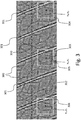
- Figure 3 shows an exemplary visual representation in grey scale of an example of said first image, that is, of a two-dimensional digital image, acquired in the visible frequency range, of an inner surface portion of a tyre illuminated with diffused light (totally similar to a common black and white picture).
- the circumferential direction of the tyre is arranged along the horizontal direction in the figure (straight line 300).
- each pixel of the digital image is associated with a scalar value (grey level or scale) in a scale of 255 levels directly representative of the reflectivity and/or diffusivity and/or colour of the inner surface point corresponding to the pixel considered.
- the present invention may also be applied to digital images in which each pixel is associated with a vector value, such as digital colour images.
- the method described herein may be carried out on each channel/colour or combinations thereof, or on a selected channel (e.g. green, which advantageously provides a better image quality).
- the digital image on which the method described herein is carried out may coincide with the digital image directly detected by the detection system or, more preferably, may be subjected, before carrying out the method described herein, to a pre-processing to improve the quality thereof.
- Said pre-processing may comprise one or more of filtering, balancing, noise reductions, smoothing, for example as known in the art.
- filtering balancing, noise reductions, smoothing, for example as known in the art.
- noise reductions smoothing
- the inner surface of the tyre is grooved by a plurality of reliefs that form a "pattern.”
- the presence of the reliefs produces a variation in the reflectivity of the inner surface detected by the camera.
- the present invention is also applicable to low relief or simply two-dimensional patterns, i.e. consisting only in a variation of colour and/or reflectivity and devoid of depth.
- the pattern comprises a series of rectilinear sections 301 substantially mutually parallel, typically distributed with substantial periodicity along the circumferential direction, and a dense network (in the jargon called 'pebble edge') of substantially rectilinear segments 302 interconnected in a substantially continuous network, the pattern being typically characterised by a substantial periodicity thereof along the circumferential direction. It is noted that the pattern develops on the inner surface of the tyre, which is provided with its own curvature.
- the pattern consists of closed broken lines (polygons) connected to each other.
- the pattern consists of polygons adjacent to each other (e.g. is devoid of isolated polygons).
- the pattern has a scheme that is repeated substantially equal thereto in a plurality of positions distributed along the circumferential direction, typically with a substantial circumferential periodicity (for example with a local period variation, in absolute value, falling within 5% of the average period calculated on the whole image), even more typically with continuity along the whole digital image.
- the pebble edge has a circumferential periodicity equal to twice the periodicity of the rifling, whereby the overall periodicity of the pattern is equal to that of the pebble edge.
- reliefs 301, 302 are the imprint left by the pneumatic bladder.
- said scheme is typically repeated along the circumferential direction with slight variations in the periodicity and/or shape and/or orientation and/or axial position, while remaining substantially equal, such variations being due for example to the non-uniformity of the bladder expansion and/or positioning, and/or to small distortions of the pattern imprinted on the bladder itself, and/or to phenomena of distortion in the image detection process (for example, due to faulty centring of the axis of rotation of the tyre, non-perfect circularity of the tyre, etc.).
- figure 3 shows a circumferential digital image portion long, along direction 300, only two and a half times around the period of the pattern; however, typically the processed digital image corresponds to a circumferential inner surface portion comprising said scheme repeated at least eight-ten times.
- the circumferential inner surface portion processed covers the entire circumferential inner development of the tyre.
- the processed digital image corresponds to a portion of the inner surface having a length in the axial direction (the direction perpendicular to direction 300 in figure 3 ) of at least 5 cm, preferably equal to at least half of the overall axial development of the tyre crown.
- Figure 3 is shown an exemplary defect 303 (shown enlarged in figure 3a which shows a rotated detail of figure 3 ) consisting in a cut that crosses at least one segment of the pattern.
- the method provides for deriving a value representative of the pattern period through digital image processing, for example by seeking a maximum of an autocorrelation function (for example, the Pearson correlation coefficient calculated on the values associated with the pixels of the image) between a given portion (in the jargon called 'support') of the digital image (having adequate dimensions, for example circumferential length greater than the period and smaller than three times the period) and a plurality of further portions of the digital image having dimensions equal the to the dimensions of said given image portion and arranged in circumferentially distributed positions.
- an autocorrelation function for example, the Pearson correlation coefficient calculated on the values associated with the pixels of the image
- the circumferential autocorrelation is repeatedly calculated with reference to multiple different supports and partially overlapping in the axial direction of the image, and having the same dimensions, with the aim of selecting the most reliable autocorrelation peak to identify the pattern period.
- it is provided to acquire a predetermined value of the period, for example from a measurement and/or from the specifications of the bladder.
- the method involves identifying a first region 304 of the digital image corresponding to a sub-portion of the scheme, for example having a smaller circumferential development than an entire circumferential development of the scheme (in the example equal to about one third of the circumferential development of the scheme, coinciding with said period).
- the dimensions of the first region are advantageously consistent with the typical expected dimensions of the defect sought.
- a first homologous region 305 is first identified by calculating the correlation function between the first region 304 and a plurality of regions having dimensions equal to the first region and arranged in a neighbourhood of a point of the digital image that is circumferentially distant from the first region by a distance equal to a period P.
- the correlation function is calculated between the first region and all the regions of the same dimensions whose centre is located in the neighbourhood of coordinates x 0 ⁇ x, y 0 +P ⁇ y, with ⁇ x, ⁇ y equal to an appropriate number of pixels, for example 5-10 pixels.
- the region having coordinates x 1 , y 1 at the centre, at which the correlation function exhibits a maximum (at least local), is identified as the first homologous region 305.
- the algorithm is repeated starting from the first homologous region 305 and seeking a correlation maximum in the neighbourhood of coordinates x 1 ⁇ x, y 1 +P ⁇ y, in order to locate the second homologous region 306 (having at the centre coordinates X 2 , y 2 ), and so on iteratively, so as to identify a sequence of homologous regions in succession.
- a tuple of coordinates X n , y n is calculated, corresponding to the centre (or any other reference point) of the tuple of homologous regions.
- the acquisition of the value representative of the pattern period by processing the digital image and identifying such tuple of coordinates are performed on the image in diffuse light (of the type shown in figure 3 ).
- This tuple of coordinates is then shown on the first image in diffuse light in order to identify a corresponding first region and a corresponding plurality of homologous regions in said first image.
- each pixel is associated with a mean value of the values associated with the pixels of the first region and of the respective homologous regions of the first image having the same coordinates of said each pixel.
- figure 4 shows a 3D graphical representation of a stack 307 of regions obtained by overlapping of the first region (for example at the base of the stack) and all its respective homologous regions of the first image in diffuse light.
- each pixel at the base of the stack corresponds to a set of statistical values (scalar, or grey scale) lying on the corresponding vertical column.
- Such statistical set has an intrinsic variance due to the deformations described above.
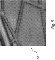
- the digital model 308 of the scheme sub-portion (shown in figure 5 ) associated with the first region 304 is calculated considering the median value of the corresponding statistical set for each pixel of the base of the stack.
- a model 308 is thus generated which has in each relative coordinate pixel (i,j) the median value (e.g. grey level) calculated on all of the relative coordinate pixels (i,j) of the set of the first region and of the homologous regions.
- the model thus calculated does not contain contributions from any defects, in addition to exhibiting a high image quality (e.g. in terms of noise and/or sharpness).
- a digital model of the respective scheme sub-portion is calculated according to the above for a plurality of first regions, each comprising the respective scheme sub-portion.
- the first regions form a connected digital image portion having circumferential development about equal to the period.
- a digital model is calculated for the whole scheme that makes up the pattern.
- the first regions are mutually partially overlapping in the axial direction and/or in the circumferential direction, in order to improve the reliability of the method.
- a pattern model is obtained by replacing, in said first image, said model of the respective scheme sub-portion to each first region and to the respective homologous regions.
- each pixel of the pattern model in luminosity values calculated on the first image it is contemplated to calculate a modulus value and an orientation value of a gradient of the luminosity values associated with the pixels, thereby obtaining a pattern model in gradient modulus values and in gradient orientation values, respectively.
- the operations described above for the identification of homologous regions and the calculation of a respective scheme sub-portion model are conducted on the gradient modulus values and on the gradient orientation values calculated on the first image in luminosity values. In this case, it is not strictly necessary to calculate the pattern model in luminosity values on the first image.
- the gradient of the luminosity values is calculated for each digital image pixel along the two horizontal and vertical coordinates of the image, thus obtaining a vector with two components: a modulus (e.g. the root of the quadratic sum of the two components) and an orientation in the digital image (e.g. the angle formed by the vector with respect to the horizontal direction), normalized in the range [0-180°] or [-90° - + 90°].
- a modulus e.g. the root of the quadratic sum of the two components
- an orientation in the digital image e.g. the angle formed by the vector with respect to the horizontal direction
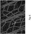
- Figure 6 shows an exemplary visualization of a surface sub-portion corresponding to a central portion of the image in figure 3 , in which each pixel is associated with a grey level representative of (e.g. proportional to) the gradient modulus in the considered pixel (e.g. light pixels correspond to a high gradient modulus and vice versa).
- Figure 7 shows an exemplary visualization of the same surface sub-portion in figure 6 , in which each pixel is associated with a grey level uniquely representative of the gradient orientation in the pixel considered.
- the pattern model is obtained in gradient modulus values and gradient orientation values, respectively.
- the resulting pattern model (be it in luminosity values and/or modulus values and/or gradient orientation values) is subjected to dilation to introduce a tolerance that takes account of the deformations and/or drifts of the scheme in the pattern.
- the pattern model in gradient modulus values is first binarised (for example by thresholding with a single or double threshold) to obtain a binary model of the pattern.
- Such binary model of the pattern is subjected to dilation (for example by means of a morphological processing operation) in order to obtain a dilated pattern binary model in which the pixels have an associated first binary index, the value of which is indicative of whether the pixel belongs or not to the dilated patterns, respectively (in order to distinguish the pixels belonging to the background from those belonging to the dilated pattern the first image by comparison with such a dilated binary model).
- each pixel of the dilated pattern binary model belonging to the dilated pattern is associated with a second index, the value of which is representative of the orientation of the dilated pattern section passing by the pixel: for example, the gradient orientation value of the pixel having maximum gradient modulus value in a predetermined neighbourhood (for example equal to 5-10 pixels of radius) of said each pixel in said pattern model may be selected.
- the gradient modulus values and the gradient orientation values of the pattern model are first both subjected to dilation.
- each pixel of the dilated pattern model is assigned as gradient modulus value the maximum value of the gradient module in a predetermined neighbourhood of said pixel in the pattern model (said neighbourhood exemplarily having a radius equal to 5-10 pixels) and as gradient orientation value that associated with the pixel having said maximum gradient modulus value.
- the pattern model thus obtained is binarised based on the gradient modulus value, thereby obtaining the value of said first index.
- Figure 8 shows an example of pattern model obtained as a result of said operations in the two embodiments.
- Each pixel of the image in figure 8 not belonging to the dilated pattern but to the pattern background (for example having value of said first index equal to zero) is shown in black.
- Each pixel belonging to the dilated pattern (for example having value of said first index equal to one) is shown in a grey level other than black, where each grey level biuniquely corresponds to a value of the second index representative of the orientation of the corresponding segment of the dilated pattern passing by the considered pixel.
- the pixels outside the dilated pattern black pixels
- Figure 9 exemplarily shows a visual representation in greyscale of a further example of a portion of the first image, of a similar nature to that shown in figure 3 and 3a , showing a further inner surface portion of a tyre illuminated with diffuse light, in which a defect 903 is present, consisting of a cut that crosses some segments of the pattern.
- a defect 903 consisting of a cut that crosses some segments of the pattern.
- On the surface portion in figure 9 there were traces of a release agent used in the bladder, in particular on the walls of the pattern segments. Since this release agent is highly reflective, such walls of the pattern segments in the image give rise to a pair of very bright parallel lines 904. A darker line 905 is present between the two bright lines which corresponds to the 'top' of the pattern segments, less dirty with release agent. In such a situation, in principle, segments 905 may be confused with cuts 903 as they have similar luminosity features.
- the Hessian matrix is calculated as follows. Being, as above, I(x,y) each pixel of the input image, the following is calculated:
- the eigenvectors and the eigenvalues are calculated, for example by the algorithm EVD (Eigen Value/Vector Decomposition).
- the main eigenvalue values are binarised by comparison with a first threshold value, in order to identify the candidate defect pixel like those pixels whose maximum eigenvalue associated is above such first threshold value.
- Figure 10 shows an exemplary visualisation of the first image portion substantially corresponding to that shown in figure 9 , binarised on the basis of the main eigenvalue. It is noted that said binarisation has enhanced both the pixels belonging to cut 903 and the pixels at walls 904 (more precisely of the transition areas between the pattern background and walls 904) and of the central areas 905 of the pattern segments where the maximum eigenvalue is high.
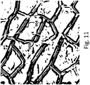
- Figure 11 substantially shows the same image portion in figure 9 wherein the pixels have been binarised on the basis of the gradient modulus (optionally with appropriate edge smoothing operations).
- the white pixels are those with low gradient modulus value, i.e. smaller than the second threshold value. It is noted that pixels 904 at the edges of the pattern segments have a high gradient value.
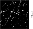
- Figure 12 substantially shows the same image portion in figure 10 , where the white pixels are the candidate defects obtained from the concurrent thresholding with said two threshold values (i.e. the white pixels both in figure 10 and in figure 11 ). It is noted that some pixels 905 remain as candidate defects at the centre of some pattern sections, while almost all pixels at the edges of the pattern sections have been substantially filtered by the criterion.
- a third selection criterion is preferably provided, preferably used in combination with said two further criteria, based on the luminosity value in the image acquired in diffuse light.
- luminosity value is compared with a third threshold value and all the candidate defect pixels as identified above are selected, which also have the luminosity value below the third threshold value.
- a first set of pixels is identified among said candidate defect pixels for which the corresponding pixels in the dilated pattern model do not belong to the dilated pattern (for example with reference to figure 8 , the black 'background' areas), to identify the defects (or defect portions) located outside the pattern, i.e. belonging to the pattern 'background'.
- a second set of pixels among said candidate defect pixels that have the corresponding pixel in the pattern model belonging to the pattern for example the pixels in grey level other than black in figure 8 , for which the at least local orientation of the pattern section passing by said dilated pattern model (represented by said second value, e.g. the orientation value of the dilated gradient) is significantly different (for example, the difference is greater than 20°) from the orientation of the section formed by said candidate defects and passing by said pixel.
- said second value e.g. the orientation value of the dilated gradient
- the orientation of the section formed by said candidate defects and passing by said pixel is represented by the gradient orientation value in said pixel calculated as described above on the luminosity values in the first image in diffuse light.
- the orientation of the section formed by said candidate defects and passing by said pixel is represented by the orientation of the main eigenvector of the Hessian matrix in said pixel calculated as described above on the luminosity values in the first image in diffuse light.
- the first and second set of pixels merge (in OR logic) the first and second set of pixels to form a final image (typically binary) representative of said surface portion wherein the pixels corresponding to said first and second set are distinct from the remaining pixels, as exemplarily shown in figure 13 , where it is seen that both the cutting portion at the pattern background and the cut portion at the dilated pattern has been identified.
- appropriate morphological processing can be carried out on said pixels in order to discard false candidate defects.
- the isolated pixels blocks or the connected pixel regions ('blob') that are not compatible with the defects sought are eliminated; in particular, the selection can be made by area and/or length.
- Figure 14 shows the end result of a processing of this type carried out on the image in figure 13 .
- Figure 15 shows a flowchart of the method according to an embodiment of the present invention, wherein operation 1010 represents operation a) of providing the tyre having a surface to be analysed having a pattern with a scheme that it repeated substantially equal thereto in a plurality of positions.
- Operation 1020 represents operation b) of acquiring one or more digital images of a surface portion wherein the pattern includes the scheme repeated a plurality of times.
- Operation 1030 represents operation c) of identifying a plurality of first regions of said one or more digital images, each first region corresponding to a respective scheme sub-portion.
- Operation 1040 represents operation d) of identifying a respective plurality of regions of said one or more digital images homologous to each first region, wherein a respective scheme sub-portion in each homologous region is substantially identical to said respective scheme sub-portion of said each first region.
- Operation 1050 represents operation e) of calculating, for each first region, a model of the respective scheme sub-portion, said scheme sub-portion model being a digital image wherein each pixel is associated with an average value of values associated with the pixels of said each first region and of the respective homologous regions having the same relative coordinates of said each pixel, thus obtaining a plurality of calculated scheme sub-portion models.
- Operation 1060 represents operation f) of obtaining a model of said pattern in said surface portion by combining said calculated scheme sub-portion models.
Landscapes
- Engineering & Computer Science (AREA)
- General Physics & Mathematics (AREA)
- Physics & Mathematics (AREA)
- Computer Vision & Pattern Recognition (AREA)
- Biochemistry (AREA)
- Immunology (AREA)
- Chemical & Material Sciences (AREA)
- Analytical Chemistry (AREA)
- Health & Medical Sciences (AREA)
- General Health & Medical Sciences (AREA)
- Theoretical Computer Science (AREA)
- Life Sciences & Earth Sciences (AREA)
- Pathology (AREA)
- Signal Processing (AREA)
- Quality & Reliability (AREA)
- Investigating Materials By The Use Of Optical Means Adapted For Particular Applications (AREA)
- Length Measuring Devices By Optical Means (AREA)
- Image Processing (AREA)
Claims (15)
- Procédé d'analyse d'une surface d'un pneu, comprenant le fait :a) de fournir le pneu (200) ayant ladite surface à analyser, où ladite surface a un motif qui est constitué d'un schéma qui est répété, de manière essentiellement égale, dans une pluralité de positions ;b) d'acquérir une ou plusieurs image(s) numérique(s) d'une partie de la surface, ladite partie de la surface étant sélectionnée de manière à ce que ledit motif dans ladite partie de surface comprenne ledit schéma répété plusieurs fois ;c) d'identifier une pluralité de premières régions (304) de ladite ou desdites plusieurs image(s) numérique (s), chaque première région correspondant à une sous-partie respective du schéma, où chaque première région comprend une pluralité de pixels caractérisés par des coordonnées relatives respectives dans ladite première région ;d) d'identifier une pluralité respective de régions (305, 306) de ladite ou desdites plusieurs image(s) numérique(s) homologues à chaque première région, où chaque région homologue comprend une pluralité de pixels caractérisés par des coordonnées relatives respectives dans ladite région homologue et où une sous-partie de schéma respective dans chaque région homologue est essentiellement identique à ladite sous-partie de schéma respective de chacune desdites premières régions ;e) de calculer, pour chaque première région (304), un modèle (308) de la sous-partie de schéma respective, ledit modèle de sous-partie de schéma étant une image numérique dans laquelle chaque pixel est associé à une valeur moyenne de valeurs associées aux pixels de chacune desdites premières régions (304) et des régions homologues respectives (305, 306) ayant les mêmes coordonnées relatives de chacun desdits pixels, obtenant ainsi une pluralité de modèles de sous-partie de schéma calculés ;f) d'obtenir un modèle dudit schéma dans ladite partie de surface en combinant lesdits modèles de sous-partie de schéma calculés.
- Procédé tel que revendiqué dans la revendication 1, dans lequel ladite pluralité de premières régions forme une partie reliée de ladite ou desdites plusieurs image(s) numérique(s) comprenant au moins ledit schéma.
- Procédé tel que revendiqué dans la revendication 1 ou 2, dans lequel lesdites premières régions se chevauchent partiellement dans une direction axiale et/ou dans une direction circonférentielle du pneu.
- Procédé tel que revendiqué dans l'une quelconque des revendications précédentes, dans lequel l'identification de ladite pluralité respective de régions homologues comprend :- le calcul d'une fonction de corrélation entre ladite première région respective et au moins une portion d'une partie restante de ladite ou desdites plusieurs image(s) numérique(s) et- l'identification d'un extremum au moins local de ladite fonction de corrélation.
- Procédé tel que revendiqué dans l'une quelconque des revendications précédentes, dans lequel ladite partie de la surface est sélectionnée de manière à ce que, dans ladite ou lesdites plusieurs image(s) numérique(s), ledit schéma soit répété, de manière essentiellement égale, au moins huit fois dans une pluralité de positions réparties le long d'une direction circonférentielle du pneu, et ladite pluralité respective de régions homologues sont réparties le long de la direction circonférentielle, où le schéma est répété, de manière essentiellement égale, le long d'une direction de périodicité avec une période essentiellement constante et où, avant d'identifier la pluralité respective de régions homologues, il est prévu d'obtenir une valeur représentative de ladite période en recherchant un maximum d'une fonction de corrélation entre une partie de ladite ou desdites plusieurs image(s) numérique(s) et une pluralité d'autres parties de ladite ou desdites plusieurs image(s) numérique(s) ayant une taille égale à la taille de ladite partie de ladite ou desdites plusieurs image(s) numérique(s) et réparties le long de ladite direction de périodicité, et où l'identification de ladite pluralité respective de régions homologues comprend l'identification d'une première région homologue respective en calculant ladite fonction de corrélation entre chacune desdites premières régions et une pluralité de régions ayant une taille égale à celle de chacune desdites premières régions et agencées autour d'un point de ladite ou desdites plusieurs image(s) numérique(s) située(s) le long de ladite direction de périodicité à une certaine distance de chacune desdites premières régions égale à un multiple entier de ladite période.
- Procédé tel que revendiqué dans l'une quelconque des revendications précédentes, dans lequel, dans le calcul dudit modèle de la sous-partie de schéma respective, ladite valeur moyenne comprend, ou est constituée de, la moyenne arithmétique et/ou géométrique, et/ou le mode, et/ou des combinaisons de ceux-ci, desdites valeurs, ou ladite valeur moyenne comprend, ou est constituée de, la valeur médiane desdites valeurs.
- Procédé tel que revendiqué dans l'une quelconque des revendications précédentes, dans lequel l'acquisition d'une ou de plusieurs image(s) numérique(s) comprend :- l'éclairage de ladite partie de surface avec une lumière diffusée et l'acquisition d'une première image dans laquelle chaque pixel est associé à une valeur de luminosité représentant la réflectivité et/ou la diffusivité et/ou la couleur d'un point de la surface correspondant à chacun desdits pixels ;- l'éclairage de ladite partie de surface avec une lumière rasante provenant respectivement de directions opposées et l'acquisition respective de deuxième et troisième images, où chaque pixel est associé à une valeur de luminosité représentant la réflectivité et/ou la diffusivité et/ou la couleur d'un point de la surface correspondant à chacun desdits pixels ;- le calcul d'une image de différence dans laquelle chaque pixel est associé à une valeur représentant la différence des valeurs de luminosité correspondantes desdites deuxième et troisième images, où l'identification de chacune desdites premières régions et de ladite pluralité respective de régions homologues comprend l'identification, au moyen d'un traitement de ladite image de différence, d'une position respective de chacune desdites premières régions et desdites régions homologues respectives dans ladite image de différence et l'identification ultérieure, dans ladite première image, d'une première région correspondante et d'une pluralité respective correspondante de régions homologues ayant lesdites positions respectives, et où ladite opération de calcul dudit modèle de ladite sous-partie de schéma respective est effectuée sur ladite première image.
- Procédé tel que revendiqué dans l'une quelconque des revendications précédentes, dans lequel, pour chaque pixel d'au moins une image parmi ladite ou lesdites plusieurs image(s) numérique(s), il est prévu de calculer un gradient desdites valeurs associées aux pixels accompagnant deux coordonnées de ladite image, ledit gradient étant un vecteur avec deux composantes représentant une variation desdites valeurs accompagnant respectivement lesdites deux coordonnées, où chaque pixel est associé à une valeur de module de gradient et une valeur d'orientation de gradient.
- Procédé tel que revendiqué dans la revendication 8, dans lequel une ou plusieurs opération(s) parmi lesdites opérations d'identification de ladite pluralité de premières régions, d'identification de ladite pluralité respective de régions homologues, de calcul dudit modèle de sous-partie de schéma respective et de calcul dudit modèle de schéma est/sont effectuée(s) en étant basée(s) sur lesdites valeurs de module de gradient et/ou sur lesdites valeurs d'orientation de gradient.
- Procédé tel que revendiqué dans les revendications 7 et 8, dans lequel, pour chaque pixel du modèle de motif calculé sur ladite première image, il est prévu de calculer ladite valeur de module de gradient et ladite valeur d'orientation de gradient de valeurs de luminosité.
- Procédé tel que revendiqué dans l'une quelconque des revendications précédentes, dans lequel un modèle de motif est obtenu en substituant, dans au moins une image parmi ladite ou lesdites plusieurs image(s), chaque première région et les régions homologues respectives par ledit modèle de sous-partie de schéma respective.
- Procédé tel que revendiqué dans l'une quelconque des revendications précédentes, comprenant la comparaison de ladite ou desdites plusieurs image(s) numérique(s) avec ledit modèle de motif et, sur la base de cette comparaison, la détection d'éventuels défauts dans ladite ou lesdites plusieurs image(s) numérique(s).
- Procédé tel que revendiqué dans l'une quelconque des revendications précédentes, comprenant le calcul d'un modèle dilaté au moyen d'une opération de dilatation effectuée sur le modèle obtenu.
- Appareil (1) d'analyse de pneus dans une chaîne de production de pneu, l'appareil comprenant :- un support (102) pour un pneu (200), adapté pour tourner autour d'un axe perpendiculaire à celui-ci ;- au moins une source (104) adaptée pour émettre au moins un rayonnement lumineux pour éclairer une partie de surface (221) du pneu, lorsqu'il est placé sur le support, et, à une certaine distance de ladite source, un système de détection (105) adapté pour détecter une intensité optique du rayonnement lumineux réfléchi et/ou diffusé par ladite partie de surface ; et- une unité de traitement (140) configurée pour actionner le procédé tel que revendiqué dans l'une quelconque des revendications précédentes.
- Appareil tel que revendiqué dans la revendication 14, dans lequel l'unité de traitement (140) est configurée pour actionner le procédé tel que revendiqué dans la revendication 7 et où le système de détection comprend une caméra linéaire ayant une ligne d'objectif (106) reposant sur un plan optique (107) passant à travers la caméra linéaire, où ladite au moins une source comprend une première source de lumière (108), une deuxième source de lumière (109) et une troisième source de lumière (110) respectivement adaptées pour émettre des premier, deuxième et troisième rayonnements lumineux pour éclairer une partie de surface linéaire (221) coïncidant avec ladite ligne d'objectif ou à proximité de celle-ci, où ladite première source de lumière et ladite deuxième source de lumière reposent respectivement sur des côtés opposés par rapport audit plan optique, où chacune desdites première et deuxième sources de lumière est adaptée pour éclairer ladite ligne d'objectif avec une lumière rasante respective, et ladite troisième source de lumière est adaptée pour éclairer ladite ligne d'objectif avec une lumière diffusée, et où l'appareil comprend une unité d'entraînement et de commande configurée :- pour activer, selon une séquence alternée, ladite première source de lumière, ladite deuxième source de lumière et ladite troisième source de lumière ; et- pour entraîner ladite caméra linéaire pour acquérir respectivement lesdites première, deuxième et troisième images de manière synchrone avec l'activation de ladite première source de lumière, de ladite deuxième source de lumière et de ladite troisième source de lumière, respectivement.
Applications Claiming Priority (2)
| Application Number | Priority Date | Filing Date | Title |
|---|---|---|---|
| ITUB20151774 | 2015-06-30 | ||
| PCT/IB2016/053679 WO2017001969A1 (fr) | 2015-06-30 | 2016-06-21 | Procédé et appareil d'analyse d'une surface d'un pneu |
Publications (2)
| Publication Number | Publication Date |
|---|---|
| EP3317855A1 EP3317855A1 (fr) | 2018-05-09 |
| EP3317855B1 true EP3317855B1 (fr) | 2020-08-05 |
Family
ID=54199992
Family Applications (1)
| Application Number | Title | Priority Date | Filing Date |
|---|---|---|---|
| EP16751337.3A Active EP3317855B1 (fr) | 2015-06-30 | 2016-06-21 | Procédé et appareil d'analyse d'une surface d'un pneu |
Country Status (6)
| Country | Link |
|---|---|
| US (1) | US10845271B2 (fr) |
| EP (1) | EP3317855B1 (fr) |
| CN (1) | CN107771341B (fr) |
| MX (1) | MX373372B (fr) |
| RU (1) | RU2707723C2 (fr) |
| WO (1) | WO2017001969A1 (fr) |
Families Citing this family (23)
| Publication number | Priority date | Publication date | Assignee | Title |
|---|---|---|---|---|
| CA2744630C (fr) | 2010-06-30 | 2018-10-09 | Camoplast Solideal Inc. | Roue de chenille pour un vehicule chenille |
| US8985250B1 (en) | 2010-12-14 | 2015-03-24 | Camoplast Solideal Inc. | Track drive mode management system and methods |
| KR102534392B1 (ko) * | 2014-12-22 | 2023-05-19 | 피렐리 타이어 소시에떼 퍼 아찌오니 | 생산라인에서 타이어를 제어하기 위한 기기 |
| RU2696343C2 (ru) | 2014-12-22 | 2019-08-01 | Пирелли Тайр С.П.А. | Способ и устройство для контроля шин на производственной линии |
| US11167810B2 (en) | 2015-03-04 | 2021-11-09 | Camso Inc. | Track system for traction of a vehicle |
| WO2017000068A1 (fr) | 2015-06-29 | 2017-01-05 | Camso Inc. | Systèmes et procédés pour surveiller un système de chenilles pour la traction d'un véhicule |
| WO2017001970A1 (fr) | 2015-06-30 | 2017-01-05 | Pirelli Tyre S.P.A. | Procédé et appareil de détection de défauts sur la surface de pneumatiques |
| US10900774B2 (en) * | 2016-07-26 | 2021-01-26 | Pirelli Tyre S.P.A. | Method for checking tyres for vehicle wheels |
| JP7210873B2 (ja) | 2017-07-26 | 2023-01-24 | 横浜ゴム株式会社 | 欠陥検査方法及び欠陥検査装置 |
| CA3085012A1 (fr) | 2017-12-08 | 2018-12-07 | Camso Inc. | Systemes et procedes de surveillance de vehicules tout-terrain |
| JP7057206B2 (ja) * | 2018-05-07 | 2022-04-19 | Toyo Tire株式会社 | タイヤ歪検出方法 |
| WO2020041899A1 (fr) * | 2018-08-30 | 2020-03-05 | Camso Inc. | Systèmes et procédés de surveillance de véhicules ayant des pneus |
| WO2020041897A1 (fr) | 2018-08-30 | 2020-03-05 | Camso Inc. | Systèmes et procédés de surveillance de véhicules à chenilles |
| CN110097542B (zh) * | 2019-04-19 | 2023-09-12 | 中山大学 | 芯片气泡的检测方法、装置及存储介质 |
| CN111179239B (zh) * | 2019-12-24 | 2022-04-26 | 浙江大学 | 一种利用背景特征进行重排名的轮胎x光瑕疵检测方法 |
| JP2021128085A (ja) * | 2020-02-14 | 2021-09-02 | 株式会社東芝 | 検査装置、検査システム及び検査プログラム |
| EP4281935A4 (fr) * | 2021-08-19 | 2024-08-07 | Samsung Electronics Co., Ltd. | Procédé et système pour générer une animation à partir d'une image statique |
| CN113781466B (zh) * | 2021-09-22 | 2024-01-19 | 河北工业大学 | 基于多尺度注意力密集网络的太阳能电池板缺陷识别方法 |
| JP7020581B1 (ja) * | 2021-10-06 | 2022-02-16 | 住友ゴム工業株式会社 | タイヤの状態の推定方法 |
| US12477207B2 (en) * | 2022-04-25 | 2025-11-18 | Enscape Co., Ltd. | Apparatus for inspecting appearance of secondary battery |
| CN116721101B (zh) * | 2023-08-09 | 2023-10-20 | 山东华航高分子材料有限公司 | 一种塑件表面波流痕的缺陷检测方法 |
| CN118505609A (zh) * | 2024-04-24 | 2024-08-16 | 东莞市富溢服装有限公司 | 基于云计算的电商服装销售价值评估系统 |
| CN119600020B (zh) * | 2025-02-08 | 2025-05-02 | 山东绿洲智能科技有限公司 | 应用于汽车轮胎的鼓包智能化测试方法 |
Family Cites Families (21)
| Publication number | Priority date | Publication date | Assignee | Title |
|---|---|---|---|---|
| JP2643058B2 (ja) * | 1991-08-26 | 1997-08-20 | 住友ゴム工業株式会社 | 空気入りラジアルタイヤ |
| JP2803067B2 (ja) * | 1993-12-09 | 1998-09-24 | 大日本スクリーン製造株式会社 | 周期性パターンの検査装置 |
| US5786533A (en) * | 1996-04-17 | 1998-07-28 | Michelin North America, Inc. | Method for analyzing a separation in a deformable structure |
| ES2286875T3 (es) * | 1999-04-22 | 2007-12-01 | Leo Vision | Procedimiento y dispositivo de tratamiento y de restitucion de imagenes, con nuevo muestreo. |
| JP4514007B2 (ja) * | 1999-12-28 | 2010-07-28 | 株式会社ブリヂストン | 被検体の外観形状検査方法及び装置 |
| DE102004050355A1 (de) * | 2004-10-15 | 2006-04-27 | Steinbichler Optotechnik Gmbh | Verfahren und Vorrichtung zum Prüfen der Oberfläche eines Reifens |
| CN1879553B (zh) * | 2005-06-15 | 2010-10-06 | 佳能株式会社 | 在胸部图像中检测边界的方法及装置 |
| DE102005031490A1 (de) * | 2005-07-04 | 2007-02-01 | Massen Machine Vision Systems Gmbh | Kostengünstige multi-sensorielle Oberflächeninspektion |
| JP4763522B2 (ja) * | 2006-06-14 | 2011-08-31 | 株式会社ブリヂストン | タイヤ検査装置 |
| US8290257B2 (en) * | 2007-03-02 | 2012-10-16 | The Procter & Gamble Company | Method and apparatus for simulation of facial skin aging and de-aging |
| EP2023078B1 (fr) * | 2007-08-06 | 2017-06-14 | Kabushiki Kaisha Kobe Seiko Sho | Système de mesure de forme de pneu |
| FR2925687B1 (fr) * | 2007-12-19 | 2010-02-12 | Soc Tech Michelin | Methode d'evaluation par comparaison d'une image acquise avec une image de reference. |
| JP5409237B2 (ja) * | 2009-09-28 | 2014-02-05 | キヤノン株式会社 | パターン検出装置、その処理方法及びプログラム |
| JP5562707B2 (ja) * | 2010-04-22 | 2014-07-30 | 株式会社ブリヂストン | タイヤ外観検査方法及びタイヤ外観検査装置 |
| FR2974218A1 (fr) * | 2011-04-18 | 2012-10-19 | Michelin Soc Tech | Analyse de l'image numerique de la surface d'un pneumatique - traitement des points de non mesure |
| FR2980896B1 (fr) | 2011-09-30 | 2016-07-01 | Soc Tech Michelin | Methode d'analyse rapide des elements en relief figurant sur la surface interne d'un pneumatique |
| US9042679B2 (en) * | 2012-06-06 | 2015-05-26 | Apple Inc. | Projection-based image registration |
| US9129155B2 (en) * | 2013-01-30 | 2015-09-08 | Aquifi, Inc. | Systems and methods for initializing motion tracking of human hands using template matching within bounded regions determined using a depth map |
| RU2529562C1 (ru) | 2013-09-11 | 2014-09-27 | Федеральное государственное унитарное предприятие "Центральный ордена Трудового Красного Знамени научно-исследовательский автомобильный и автомоторный институт "НАМИ" | Стенд для исследования автомобильной шины |
| US9305338B1 (en) * | 2013-12-13 | 2016-04-05 | Pixelworks, Inc. | Image detail enhancement and edge sharpening without overshooting |
| WO2017001970A1 (fr) | 2015-06-30 | 2017-01-05 | Pirelli Tyre S.P.A. | Procédé et appareil de détection de défauts sur la surface de pneumatiques |
-
2016
- 2016-06-21 EP EP16751337.3A patent/EP3317855B1/fr active Active
- 2016-06-21 WO PCT/IB2016/053679 patent/WO2017001969A1/fr not_active Ceased
- 2016-06-21 US US15/737,066 patent/US10845271B2/en active Active
- 2016-06-21 CN CN201680034971.5A patent/CN107771341B/zh active Active
- 2016-06-21 RU RU2018101232A patent/RU2707723C2/ru active
- 2016-06-21 MX MX2017016137A patent/MX373372B/es active IP Right Grant
Non-Patent Citations (1)
| Title |
|---|
| None * |
Also Published As
| Publication number | Publication date |
|---|---|
| RU2018101232A3 (fr) | 2019-09-30 |
| MX373372B (es) | 2020-04-16 |
| EP3317855A1 (fr) | 2018-05-09 |
| RU2707723C2 (ru) | 2019-11-28 |
| CN107771341A (zh) | 2018-03-06 |
| MX2017016137A (es) | 2018-06-18 |
| CN107771341B (zh) | 2022-01-11 |
| RU2018101232A (ru) | 2019-07-31 |
| US20180172557A1 (en) | 2018-06-21 |
| WO2017001969A1 (fr) | 2017-01-05 |
| US10845271B2 (en) | 2020-11-24 |
Similar Documents
| Publication | Publication Date | Title |
|---|---|---|
| US10878558B2 (en) | Method and apparatus for detecting defects on the surface of tyres | |
| US10845271B2 (en) | Method and apparatus for analyzing a surface of a tyre | |
| EP3317635B1 (fr) | Procédé et appareil de détection de défauts sur la surface de pneumatiques | |
| EP2880415B1 (fr) | Procédé de segmentation de la surface d'un pneu et appareil fonctionnant selon ledit procédé | |
| CN103168220B (zh) | 用于识别和定义形成轮胎胎面设计的基本花纹的方法 | |
| EP3237876B1 (fr) | Procede et appareil de detection de défauts en pneumatiques en une chaîne de production | |
| JP6789292B2 (ja) | タイヤを検査する方法および装置 | |
| EP3237837B1 (fr) | Procédé et appareil pour contrôler des pneus dans une chaîne de production | |
| JP7210873B2 (ja) | 欠陥検査方法及び欠陥検査装置 | |
| JP2011506989A (ja) | 基準画像との比較による収集画像の評価方法 | |
| US10697762B2 (en) | Apparatus for controlling tyres in a production line | |
| BR112017027002B1 (pt) | Método para analisar uma superfície de um pneu, e, aparelho para analisar pneus em uma linha de produção de pneu |
Legal Events
| Date | Code | Title | Description |
|---|---|---|---|
| STAA | Information on the status of an ep patent application or granted ep patent |
Free format text: STATUS: THE INTERNATIONAL PUBLICATION HAS BEEN MADE |
|
| PUAI | Public reference made under article 153(3) epc to a published international application that has entered the european phase |
Free format text: ORIGINAL CODE: 0009012 |
|
| STAA | Information on the status of an ep patent application or granted ep patent |
Free format text: STATUS: REQUEST FOR EXAMINATION WAS MADE |
|
| 17P | Request for examination filed |
Effective date: 20180115 |
|
| AK | Designated contracting states |
Kind code of ref document: A1 Designated state(s): AL AT BE BG CH CY CZ DE DK EE ES FI FR GB GR HR HU IE IS IT LI LT LU LV MC MK MT NL NO PL PT RO RS SE SI SK SM TR |
|
| AX | Request for extension of the european patent |
Extension state: BA ME |
|
| DAV | Request for validation of the european patent (deleted) | ||
| DAX | Request for extension of the european patent (deleted) | ||
| REG | Reference to a national code |
Ref country code: DE Ref legal event code: R079 Ref document number: 602016041405 Country of ref document: DE Free format text: PREVIOUS MAIN CLASS: G06T0007000000 Ipc: G01N0021952000 |
|
| GRAP | Despatch of communication of intention to grant a patent |
Free format text: ORIGINAL CODE: EPIDOSNIGR1 |
|
| STAA | Information on the status of an ep patent application or granted ep patent |
Free format text: STATUS: GRANT OF PATENT IS INTENDED |
|
| RIC1 | Information provided on ipc code assigned before grant |
Ipc: G01M 17/02 20060101ALI20200401BHEP Ipc: G01N 21/956 20060101ALI20200401BHEP Ipc: G01N 21/88 20060101ALI20200401BHEP Ipc: G06T 7/00 20170101ALI20200401BHEP Ipc: G01N 21/952 20060101AFI20200401BHEP |
|
| INTG | Intention to grant announced |
Effective date: 20200421 |
|
| RIN1 | Information on inventor provided before grant (corrected) |
Inventor name: BALLARDINI, VALERIANO Inventor name: REGOLI, FABIO Inventor name: DI STEFANO, LUIGI Inventor name: GHIDOTTI PIOVAN, ALESSANDRO Inventor name: BOFFA, VINCENZO |
|
| GRAS | Grant fee paid |
Free format text: ORIGINAL CODE: EPIDOSNIGR3 |
|
| GRAA | (expected) grant |
Free format text: ORIGINAL CODE: 0009210 |
|
| STAA | Information on the status of an ep patent application or granted ep patent |
Free format text: STATUS: THE PATENT HAS BEEN GRANTED |
|
| AK | Designated contracting states |
Kind code of ref document: B1 Designated state(s): AL AT BE BG CH CY CZ DE DK EE ES FI FR GB GR HR HU IE IS IT LI LT LU LV MC MK MT NL NO PL PT RO RS SE SI SK SM TR |
|
| REG | Reference to a national code |
Ref country code: GB Ref legal event code: FG4D |
|
| REG | Reference to a national code |
Ref country code: CH Ref legal event code: EP |
|
| REG | Reference to a national code |
Ref country code: AT Ref legal event code: REF Ref document number: 1299413 Country of ref document: AT Kind code of ref document: T Effective date: 20200815 |
|
| REG | Reference to a national code |
Ref country code: DE Ref legal event code: R096 Ref document number: 602016041405 Country of ref document: DE |
|
| REG | Reference to a national code |
Ref country code: IE Ref legal event code: FG4D |
|
| REG | Reference to a national code |
Ref country code: LT Ref legal event code: MG4D |
|
| REG | Reference to a national code |
Ref country code: NL Ref legal event code: MP Effective date: 20200805 |
|
| REG | Reference to a national code |
Ref country code: AT Ref legal event code: MK05 Ref document number: 1299413 Country of ref document: AT Kind code of ref document: T Effective date: 20200805 |
|
| PG25 | Lapsed in a contracting state [announced via postgrant information from national office to epo] |
Ref country code: SE Free format text: LAPSE BECAUSE OF FAILURE TO SUBMIT A TRANSLATION OF THE DESCRIPTION OR TO PAY THE FEE WITHIN THE PRESCRIBED TIME-LIMIT Effective date: 20200805 Ref country code: GR Free format text: LAPSE BECAUSE OF FAILURE TO SUBMIT A TRANSLATION OF THE DESCRIPTION OR TO PAY THE FEE WITHIN THE PRESCRIBED TIME-LIMIT Effective date: 20201106 Ref country code: FI Free format text: LAPSE BECAUSE OF FAILURE TO SUBMIT A TRANSLATION OF THE DESCRIPTION OR TO PAY THE FEE WITHIN THE PRESCRIBED TIME-LIMIT Effective date: 20200805 Ref country code: ES Free format text: LAPSE BECAUSE OF FAILURE TO SUBMIT A TRANSLATION OF THE DESCRIPTION OR TO PAY THE FEE WITHIN THE PRESCRIBED TIME-LIMIT Effective date: 20200805 Ref country code: PT Free format text: LAPSE BECAUSE OF FAILURE TO SUBMIT A TRANSLATION OF THE DESCRIPTION OR TO PAY THE FEE WITHIN THE PRESCRIBED TIME-LIMIT Effective date: 20201207 Ref country code: NO Free format text: LAPSE BECAUSE OF FAILURE TO SUBMIT A TRANSLATION OF THE DESCRIPTION OR TO PAY THE FEE WITHIN THE PRESCRIBED TIME-LIMIT Effective date: 20201105 Ref country code: AT Free format text: LAPSE BECAUSE OF FAILURE TO SUBMIT A TRANSLATION OF THE DESCRIPTION OR TO PAY THE FEE WITHIN THE PRESCRIBED TIME-LIMIT Effective date: 20200805 Ref country code: HR Free format text: LAPSE BECAUSE OF FAILURE TO SUBMIT A TRANSLATION OF THE DESCRIPTION OR TO PAY THE FEE WITHIN THE PRESCRIBED TIME-LIMIT Effective date: 20200805 Ref country code: BG Free format text: LAPSE BECAUSE OF FAILURE TO SUBMIT A TRANSLATION OF THE DESCRIPTION OR TO PAY THE FEE WITHIN THE PRESCRIBED TIME-LIMIT Effective date: 20201105 Ref country code: LT Free format text: LAPSE BECAUSE OF FAILURE TO SUBMIT A TRANSLATION OF THE DESCRIPTION OR TO PAY THE FEE WITHIN THE PRESCRIBED TIME-LIMIT Effective date: 20200805 |
|
| PG25 | Lapsed in a contracting state [announced via postgrant information from national office to epo] |
Ref country code: NL Free format text: LAPSE BECAUSE OF FAILURE TO SUBMIT A TRANSLATION OF THE DESCRIPTION OR TO PAY THE FEE WITHIN THE PRESCRIBED TIME-LIMIT Effective date: 20200805 Ref country code: PL Free format text: LAPSE BECAUSE OF FAILURE TO SUBMIT A TRANSLATION OF THE DESCRIPTION OR TO PAY THE FEE WITHIN THE PRESCRIBED TIME-LIMIT Effective date: 20200805 Ref country code: LV Free format text: LAPSE BECAUSE OF FAILURE TO SUBMIT A TRANSLATION OF THE DESCRIPTION OR TO PAY THE FEE WITHIN THE PRESCRIBED TIME-LIMIT Effective date: 20200805 Ref country code: RS Free format text: LAPSE BECAUSE OF FAILURE TO SUBMIT A TRANSLATION OF THE DESCRIPTION OR TO PAY THE FEE WITHIN THE PRESCRIBED TIME-LIMIT Effective date: 20200805 Ref country code: IS Free format text: LAPSE BECAUSE OF FAILURE TO SUBMIT A TRANSLATION OF THE DESCRIPTION OR TO PAY THE FEE WITHIN THE PRESCRIBED TIME-LIMIT Effective date: 20201205 |
|
| PG25 | Lapsed in a contracting state [announced via postgrant information from national office to epo] |
Ref country code: EE Free format text: LAPSE BECAUSE OF FAILURE TO SUBMIT A TRANSLATION OF THE DESCRIPTION OR TO PAY THE FEE WITHIN THE PRESCRIBED TIME-LIMIT Effective date: 20200805 Ref country code: SM Free format text: LAPSE BECAUSE OF FAILURE TO SUBMIT A TRANSLATION OF THE DESCRIPTION OR TO PAY THE FEE WITHIN THE PRESCRIBED TIME-LIMIT Effective date: 20200805 Ref country code: RO Free format text: LAPSE BECAUSE OF FAILURE TO SUBMIT A TRANSLATION OF THE DESCRIPTION OR TO PAY THE FEE WITHIN THE PRESCRIBED TIME-LIMIT Effective date: 20200805 Ref country code: DK Free format text: LAPSE BECAUSE OF FAILURE TO SUBMIT A TRANSLATION OF THE DESCRIPTION OR TO PAY THE FEE WITHIN THE PRESCRIBED TIME-LIMIT Effective date: 20200805 Ref country code: CZ Free format text: LAPSE BECAUSE OF FAILURE TO SUBMIT A TRANSLATION OF THE DESCRIPTION OR TO PAY THE FEE WITHIN THE PRESCRIBED TIME-LIMIT Effective date: 20200805 |
|
| REG | Reference to a national code |
Ref country code: DE Ref legal event code: R097 Ref document number: 602016041405 Country of ref document: DE |
|
| PG25 | Lapsed in a contracting state [announced via postgrant information from national office to epo] |
Ref country code: AL Free format text: LAPSE BECAUSE OF FAILURE TO SUBMIT A TRANSLATION OF THE DESCRIPTION OR TO PAY THE FEE WITHIN THE PRESCRIBED TIME-LIMIT Effective date: 20200805 |
|
| PLBE | No opposition filed within time limit |
Free format text: ORIGINAL CODE: 0009261 |
|
| STAA | Information on the status of an ep patent application or granted ep patent |
Free format text: STATUS: NO OPPOSITION FILED WITHIN TIME LIMIT |
|
| PG25 | Lapsed in a contracting state [announced via postgrant information from national office to epo] |
Ref country code: SK Free format text: LAPSE BECAUSE OF FAILURE TO SUBMIT A TRANSLATION OF THE DESCRIPTION OR TO PAY THE FEE WITHIN THE PRESCRIBED TIME-LIMIT Effective date: 20200805 |
|
| 26N | No opposition filed |
Effective date: 20210507 |
|
| PG25 | Lapsed in a contracting state [announced via postgrant information from national office to epo] |
Ref country code: SI Free format text: LAPSE BECAUSE OF FAILURE TO SUBMIT A TRANSLATION OF THE DESCRIPTION OR TO PAY THE FEE WITHIN THE PRESCRIBED TIME-LIMIT Effective date: 20200805 |
|
| PG25 | Lapsed in a contracting state [announced via postgrant information from national office to epo] |
Ref country code: MC Free format text: LAPSE BECAUSE OF FAILURE TO SUBMIT A TRANSLATION OF THE DESCRIPTION OR TO PAY THE FEE WITHIN THE PRESCRIBED TIME-LIMIT Effective date: 20200805 |
|
| REG | Reference to a national code |
Ref country code: CH Ref legal event code: PL |
|
| REG | Reference to a national code |
Ref country code: BE Ref legal event code: MM Effective date: 20210630 |
|
| PG25 | Lapsed in a contracting state [announced via postgrant information from national office to epo] |
Ref country code: LU Free format text: LAPSE BECAUSE OF NON-PAYMENT OF DUE FEES Effective date: 20210621 |
|
| PG25 | Lapsed in a contracting state [announced via postgrant information from national office to epo] |
Ref country code: LI Free format text: LAPSE BECAUSE OF NON-PAYMENT OF DUE FEES Effective date: 20210630 Ref country code: IE Free format text: LAPSE BECAUSE OF NON-PAYMENT OF DUE FEES Effective date: 20210621 Ref country code: CH Free format text: LAPSE BECAUSE OF NON-PAYMENT OF DUE FEES Effective date: 20210630 |
|
| PG25 | Lapsed in a contracting state [announced via postgrant information from national office to epo] |
Ref country code: BE Free format text: LAPSE BECAUSE OF NON-PAYMENT OF DUE FEES Effective date: 20210630 |
|
| PG25 | Lapsed in a contracting state [announced via postgrant information from national office to epo] |
Ref country code: CY Free format text: LAPSE BECAUSE OF FAILURE TO SUBMIT A TRANSLATION OF THE DESCRIPTION OR TO PAY THE FEE WITHIN THE PRESCRIBED TIME-LIMIT Effective date: 20200805 |
|
| PG25 | Lapsed in a contracting state [announced via postgrant information from national office to epo] |
Ref country code: HU Free format text: LAPSE BECAUSE OF FAILURE TO SUBMIT A TRANSLATION OF THE DESCRIPTION OR TO PAY THE FEE WITHIN THE PRESCRIBED TIME-LIMIT; INVALID AB INITIO Effective date: 20160621 |
|
| PG25 | Lapsed in a contracting state [announced via postgrant information from national office to epo] |
Ref country code: MK Free format text: LAPSE BECAUSE OF FAILURE TO SUBMIT A TRANSLATION OF THE DESCRIPTION OR TO PAY THE FEE WITHIN THE PRESCRIBED TIME-LIMIT Effective date: 20200805 |
|
| PG25 | Lapsed in a contracting state [announced via postgrant information from national office to epo] |
Ref country code: MT Free format text: LAPSE BECAUSE OF FAILURE TO SUBMIT A TRANSLATION OF THE DESCRIPTION OR TO PAY THE FEE WITHIN THE PRESCRIBED TIME-LIMIT Effective date: 20200805 |
|
| PGFP | Annual fee paid to national office [announced via postgrant information from national office to epo] |
Ref country code: DE Payment date: 20250627 Year of fee payment: 10 |
|
| PGFP | Annual fee paid to national office [announced via postgrant information from national office to epo] |
Ref country code: GB Payment date: 20250627 Year of fee payment: 10 |
|
| PGFP | Annual fee paid to national office [announced via postgrant information from national office to epo] |
Ref country code: FR Payment date: 20250625 Year of fee payment: 10 |
|
| PGFP | Annual fee paid to national office [announced via postgrant information from national office to epo] |
Ref country code: IT Payment date: 20250619 Year of fee payment: 10 |
|
| PG25 | Lapsed in a contracting state [announced via postgrant information from national office to epo] |
Ref country code: TR Free format text: LAPSE BECAUSE OF FAILURE TO SUBMIT A TRANSLATION OF THE DESCRIPTION OR TO PAY THE FEE WITHIN THE PRESCRIBED TIME-LIMIT Effective date: 20200805 |