EP3318162A1 - Lit basculant modulaire à commande programmable - Google Patents
Lit basculant modulaire à commande programmable Download PDFInfo
- Publication number
- EP3318162A1 EP3318162A1 EP16197183.3A EP16197183A EP3318162A1 EP 3318162 A1 EP3318162 A1 EP 3318162A1 EP 16197183 A EP16197183 A EP 16197183A EP 3318162 A1 EP3318162 A1 EP 3318162A1
- Authority
- EP
- European Patent Office
- Prior art keywords
- motion
- leg
- bed
- rocking
- sensors
- Prior art date
- Legal status (The legal status is an assumption and is not a legal conclusion. Google has not performed a legal analysis and makes no representation as to the accuracy of the status listed.)
- Withdrawn
Links
- 230000033001 locomotion Effects 0.000 claims abstract description 208
- 230000008093 supporting effect Effects 0.000 claims abstract description 57
- 238000004891 communication Methods 0.000 claims abstract description 30
- 230000007246 mechanism Effects 0.000 claims abstract description 30
- 230000003534 oscillatory effect Effects 0.000 claims abstract description 21
- 238000000034 method Methods 0.000 claims abstract description 19
- 230000007177 brain activity Effects 0.000 claims abstract description 13
- 230000036772 blood pressure Effects 0.000 claims abstract description 12
- 239000003638 chemical reducing agent Substances 0.000 claims abstract description 10
- 230000001960 triggered effect Effects 0.000 claims description 7
- 230000000903 blocking effect Effects 0.000 claims description 6
- 230000010355 oscillation Effects 0.000 claims description 6
- 238000009434 installation Methods 0.000 claims description 3
- 230000003213 activating effect Effects 0.000 claims 1
- 230000000694 effects Effects 0.000 claims 1
- 230000004075 alteration Effects 0.000 abstract 1
- 230000008901 benefit Effects 0.000 description 8
- 230000003068 static effect Effects 0.000 description 6
- 230000001360 synchronised effect Effects 0.000 description 6
- 229920000642 polymer Polymers 0.000 description 4
- 230000001939 inductive effect Effects 0.000 description 3
- 230000003319 supportive effect Effects 0.000 description 3
- 230000004913 activation Effects 0.000 description 2
- 230000000712 assembly Effects 0.000 description 2
- 238000000429 assembly Methods 0.000 description 2
- 230000009849 deactivation Effects 0.000 description 2
- 230000004617 sleep duration Effects 0.000 description 2
- 230000009466 transformation Effects 0.000 description 2
- 210000000707 wrist Anatomy 0.000 description 2
- 230000036626 alertness Effects 0.000 description 1
- 238000013459 approach Methods 0.000 description 1
- 230000001914 calming effect Effects 0.000 description 1
- 230000006835 compression Effects 0.000 description 1
- 238000007906 compression Methods 0.000 description 1
- 238000010276 construction Methods 0.000 description 1
- 230000008878 coupling Effects 0.000 description 1
- 238000010168 coupling process Methods 0.000 description 1
- 238000005859 coupling reaction Methods 0.000 description 1
- 230000003247 decreasing effect Effects 0.000 description 1
- 238000006073 displacement reaction Methods 0.000 description 1
- 229940079593 drug Drugs 0.000 description 1
- 239000003814 drug Substances 0.000 description 1
- 230000006870 function Effects 0.000 description 1
- 238000004519 manufacturing process Methods 0.000 description 1
- 230000004048 modification Effects 0.000 description 1
- 238000012986 modification Methods 0.000 description 1
- 238000012544 monitoring process Methods 0.000 description 1
- 208000019116 sleep disease Diseases 0.000 description 1
- 230000004622 sleep time Effects 0.000 description 1
Images




Classifications
-
- A—HUMAN NECESSITIES
- A47—FURNITURE; DOMESTIC ARTICLES OR APPLIANCES; COFFEE MILLS; SPICE MILLS; SUCTION CLEANERS IN GENERAL
- A47C—CHAIRS; SOFAS; BEDS
- A47C21/00—Attachments for beds, e.g. sheet holders or bed-cover holders; Ventilating, cooling or heating means in connection with bedsteads or mattresses
- A47C21/006—Oscillating, balancing or vibrating mechanisms connected to the bedstead
-
- A—HUMAN NECESSITIES
- A47—FURNITURE; DOMESTIC ARTICLES OR APPLIANCES; COFFEE MILLS; SPICE MILLS; SUCTION CLEANERS IN GENERAL
- A47D—FURNITURE SPECIALLY ADAPTED FOR CHILDREN
- A47D9/00—Cradles ; Bassinets
- A47D9/02—Cradles ; Bassinets with rocking mechanisms
- A47D9/04—Cradles ; Bassinets with rocking mechanisms with disconnectable rockers
-
- A—HUMAN NECESSITIES
- A47—FURNITURE; DOMESTIC ARTICLES OR APPLIANCES; COFFEE MILLS; SPICE MILLS; SUCTION CLEANERS IN GENERAL
- A47D—FURNITURE SPECIALLY ADAPTED FOR CHILDREN
- A47D9/00—Cradles ; Bassinets
- A47D9/02—Cradles ; Bassinets with rocking mechanisms
- A47D9/057—Cradles ; Bassinets with rocking mechanisms driven by electric motors
Definitions
- This invention relates to rocking mechanisms for beds, cribs, and the like, and more particularly to an apparatus and a method of controlling the same, which imparts an oscillatory movement in a horizontal plane.
- the invention also relates to a device for automatically moving at least one piece of furniture, wherein the device is connected in a detachable manner to the piece of furniture.
- the present invention uses modular supporting legs which can be readily attached to a standard bed frame without altering the last. Furthermore, specifically to the object of the invention, the bed oscillatory motion is generated within the supporting legs.
- the oscillatory motion may be activated, deactivated and parameterized based on the user sleep status in an automated manner using motion, temperature, heart rate, blood pressure, brain activity and weight sensors.
- the oscillatory motion characteristics are also user configurable through a control panel, or remotely from a terminal connected to a data communication network.
- a rocking or swinging bed may also help those with sleep disorders to achieve a full night sleep without the need of using medication.
- the rocking beds main technical problem is the size and complexity of the device which produces the oscillatory motion.
- Many of the known devices require a special construction which imply large production costs and storage space.
- the patent US3934283 uses two vibrator motors which are attached to opposite rail portions of the bed frame. This has the disadvantage of inducing the vibration to the whole bed structure including the legs and implicitly also the floor. This is prone to quick mechanical wear, which is not the case of the present invention that has the advantage of inducing the oscillatory motion through an actuator mechanism which decouples the fixed supporting structure which lies on the floor from the moving apparatus which connects to the bed frame.
- rocking devices for babies have the disadvantage of being applicable only to some particular types of cots, and assume that the cots have specific legs shape. This is the case of patents EP1900311 , US4793010 and WO2005084497 which assume that the cot legs would fit inside the rocking apparatus.
- the proposed invention has the advantage of being applicable also to any baby cot legs shape and size, by proposing a generic leg holder mechanism. Furthermore, unlike the proposed invention, the technical solutions adopted by these three existing patents are not suitable for the weight and size of an adult rocking bed.
- the object of the present invention is achieved by the rocking apparatus with the features of Claim 1, 3, 8, and the motion control method with the features of Claim 9.
- a primary object of the present invention is to provide a modular rocking apparatus, comprising of a support structure, which include four supporting legs, at least one of supporting legs including or being associated with a motion imparting mechanism.
- the leg with a motion imparting mechanism contains a support structure, an electric motor, a gear reducer coupled to the motor, a leadscrew rod which is coupled to the gear reducer, a moving block which contains a screw nut in which the leadscrew rod is accommodated, two guiding rods on which the moving block slides mounted on linear bearings, a frame supporting structure which is mounted on the moving block, a decorative housing, and a linkage assembly which is mounted on top of the decorative housing.
- the linkage assembly may be adjusted against the decorative housing in order to accommodate any bed frame shape and bed linkage mechanism.
- the motion is imparted by the assembly of the electric motor, gear reducer and leadscrew rod which form an actuator mechanism, and which transforms the electric motor rotation motion into a linear motion.
- the modular rocking apparatus may also use passive legs.
- the term "passive leg” as used throughout the specification imply any form of supporting structure which doesn't include a motion imparting mechanism, and which facilitates the continuation of the motion imparted by the motion imparting leg.
- the passive leg contains a support structure, a motion blocking mechanism which disables the leg free motion before the installation, a moving block which is coupled to the motion blocking mechanism, two guiding rods on which the moving block slides mounted on linear bearings, a frame supporting structure which is mounted on the moving block, a decorative housing, and a linkage assembly which is mounted on top of the decorative housing.
- the linkage assembly may be adjusted against the frame decorative housing in order to accommodate any bed frame shape, and bed linkage mechanism.
- two legs include or are associated with motion imparting means, and two legs are passive.
- Each motion imparting leg may be connected to a passive leg through one or more connecting rods.
- the rods are made of smaller segments with screws and nuts endings, which could accommodate several joints to form a variable length rod.
- This approach has the advantage that the variable length rods could fit any bed width.
- One of the rods is connected to the lower leg supporting structure which resides on the floor and the other rod is connected to the higher part of the leg which moves in an oscillatory manner.
- This mechanism that uses rods to transmit the rocking motion force from the motion imparting leg to a passive leg keeps the legs aligned and reduce the force which is applied to the bed frame.
- the rods are optional provided that the bed frame could handle the force generated by the motion imparting legs towards the passive legs, and the passive leg bases are not misaligned accidentally by the user during operation.
- the last is applicable to any adult or child bed size and shape.
- all the legs could be motion imparting legs.
- the motion imparted to the bed is an oscillating or reciprocating motion.
- the present invention provides an apparatus which comprise an electric motor driver for each electric motor, a microcontroller unit which synchronizes further all the electric motor drivers, and a pair of switches inside each leg which detect the end of the oscillatory motion path. These switches are triggered at the end of the motion path, and they command the rotation sense for all the motion imparting motors in a synchronous manner.
- the present invention provides a method for controlling the rocking bed apparatus activation, deactivation and motion parameters.
- the method comprises: firstly, the method determines whether the user lies down on the bed by the means of a weight sensor and at least one motion detector sensor, and secondly it sets the user desired rocking motion characteristics by the means of the apparatus control panel settings, or remotely from the settings at a terminal through a wireless or wired data network, or based on parameters derived from sensors which monitor the user temperature, heart rate, blood pressure and brain activity.
- the displacement of the rocking motion may be changed based on configuration commands which contain and are not limited to motion speed, rocking duration after the user falls asleep, and the total desired sleep duration after which the rocking motion is disabled.
- Another advantage and feature of the invention is the possibility to monitor remotely the user through the means of information provided by motion, temperature, heart rate, blood pressure and brain activity sensors. This could be applicable for monitoring infants, patients in hospitals, or elderly people in care homes.
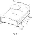
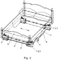
- a rocking apparatus 10 for a bed 9 in accordance with the preferred embodiment of the present invention comprises two motion imparting legs 1, two passive legs 2, two pairs of rods which comprise multiple connected segments 4 and 5, a motion and communication control unit 6, two motion sensors 7, and the electric wires 8 which connect the motion imparting legs 1 and passive legs 2 to the motion and communication control unit 6.
- the last communicates with a data network 11 and other connected devices which are further described in relation to Fig. 27 .
- the motion imparting leg 1 includes a flat base 1.21, a decorative housing 1.24, and a linkage assembly 1.20 that is used for securing the bed frame to the motion imparting leg 1.
- the passive leg 2 includes a flat base 2.1, a decorative housing 2.13, and a linkage assembly 2.10 that is used for securing the bed frame to the passive leg 2.
- Each motion imparting leg 1 is connected to a passive leg 2 through two rods that include alternated segments which are ended on both ends with nuts 4, and segments ended on both ends with screws 5, that are screwed into each other in order to form any desired length, in accordance with any bed width.
- the segments 4 and 5 are secured and tightened together by the nuts 4.1.
- One of the rod assemblies keeps the lower part of the motion imparting legs base 1.21 equally spaced and aligned to the passive leg lower part 2.1.
- the other rod assembly keeps the motion imparting legs decorative housing 1.24 along with the upper moving mechanism, equally spaced and aligned to the passive leg upper moving mechanism and decorative housing 2.13.
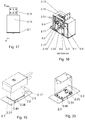
- the rods coupling to the legs will become apparent from the following descriptions of Fig 5-10 , 13-18 , and 21-26 .
- the rocking apparatus 10 that comprises four motion imparting legs 1, a motion and communication control unit 6, two motion sensors 7, and the electric wires 8 which connect the motion imparting legs 1 to the motion and communication control unit 6.
- the last communicates with a data network 11 and other connected devices which are further described in relation to Fig. 28 .
- all the legs 1 contain a motion imparting mechanism, there is no need for connecting rods in between the legs 1, as all the last impart synchronously a rocking motion to the bed.
- the rocking apparatus 10 may use either the motion imparting legs 1 or 3.
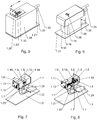
- the motion imparting leg 1 comprises a flat base 1.21 which is welded to a rectangular pipe 1.12, that accommodates internally the motion imparting actuator and a supportive structure.
- the motion imparting mechanism comprise an electric motor 1.1 which is mounted on a U shape support structure 1.11, a worm gear reducer which includes a worm 1.2 mounted on the motor 1.1 shaft and a toothed wheel 1.4 mounted on the shaft of the leadscrew rod 1.5.
- the worm 1.2 is secured on the motor shaft by the screw 1.3
- the toothed wheel 1.4 is secured to the shaft of the leadscrew rod 1.5, by the screw 1.6.
- the leadscrew rod 1.5 is supported at both ends by the bearings 1.7 and 1.15.
- the leadscrew rod 1.5 is supported as well by the bearing 1.7 which is mounted on the side of the worm gear housing 1.14.
- the motion is imparted in a horizontal plane along the axis of the two supporting rods 1.10, by the transformation of the rotary motion of the leadscrew rod 1.5 into a linear motion induced to the moving block 1.8.
- the moving block 1.8 includes a nut threading which accommodates the leadscrew rod 1.5, two cylindrical housings for the linear bearings 1.9, and six threaded holes which accommodate the screws 1.32, 1.33 and 1.3 8.
- the linear bearings 1.9 slide along with the moving block 1.8 on the two supporting rods 1.10, in accordance with the motion induced by the rotation of the leadscrew rod 1.5.
- the supporting rods 1.10 are fastened on both sides against the U shape support structure 1.11 and the leg rectangular pipe 1.12 by the screws 1.13.
- the end of the oscillatory motion path is detected electronically by the means of two switches “single-pole, single-throw" (on or off) 1.22 which are mounted on the U shape support structure 1.11.
- On the lower side of the moving block 1.8 there are two perpendicular flat boards 1.23 arranged on opposite sides, that trigger the switches 1.22 when the moving block 1.8 reaches either end of the motion path.
- the switches 1.22 may be used only for the first round that the rocking apparatus imparts an oscillating motion. The subsequent oscillating motions don't need to use the switches 1.22 to detect the end of the movement path, as the control logic of the motion control unit 6 ( Fig. 1 ) stores in its memory the location of the switches 1.22. More information regarding the switches logic will be included further down in the motion control and communication unit 6 description.
- the motor 1.1 electric cables and the switches 1.22 electric cables are protected by a housing 1.29 which is mounted on the flat base 1.21.
- the housing 1.29 shields the electric cables for being tangled by the decorative housing 1.24 when the last moves against the flat base 1.21.
- the frame supporting structure 1.18 is mounted on the moving block 1.8 using the screws 1.38 (as seen in Fig. 7 ).
- the flat sheet 1.19 is welded to the frame supporting structure 1.18 in order to increase the last mechanical resistance.
- the decorative housing 1.24 wraps and hides the supporting structure 1.18 and the internal leg mechanism. As shown in Fig 9 , there is no physical contact between the decorative housing 1.24 and the leg lower side which includes the flat base 1.21, the electric cables housing 1.29 and the rectangular pipe 1.12.
- the oscillatory motion is imparted in a horizontal plane to the moving block 1.8, to the connected supporting structure 1.18, to the decorative housing 1.24, to the linkage assembly 1.20 and to the bolt 1.25.
- the bolt 1.25 is rigidly mounted on the supporting structure 1.18 and passes unobstructed through the decorative housing 1.24.
- the other bolt 1.30 is mounted onto the U shape support structure 1.11 and passes through the frame supporting structure 1.18 and the decorative housing 1.24. There is no physical contact between the bolt 1.30 and the frame supporting structure 1.18 and neither the decorative housing 1.24.
- the bolt 1.25 is connected to the leg 1 moving apparatus, and the bolt 1.30 is connected to the leg 1 static lower part.
- the legs connecting rods that comprise rod segments 4 may be screwed into the bolt 1.25 and tightened with the nut 4.1.
- the other connecting rod is screwed into the bolt 1.30.
- the connection between the motion imparting leg 1 and the passive leg 2 is done through the connecting rod segments 4 and 5 which keep the legs mobile and static parts synchronized.
- the linkage assembly 1.20 is tightened against the decorative housing 1.24 and the moving block 1.8 using the screws 1.32 and 1.33.
- the linkage assembly 1.20 comprise two parallel groove cuts which allow to adjust the linkage assembly 1.20 relative position against the decorative housing 1.24. By loosening the screws 1.32 and 1.33 the linkage assembly 1.20 may be moved inwards or outwards the leg's edge in order to match any bed frame width.
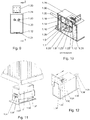
- Fig. 11 it discloses a generic supporting structure for holding an existing bed 9 leg, which could be applicable to a motion imparting leg or a passive leg.
- Some beds for adults and children have preassembled legs which could be mounted (as shown in Fig. 11 ) on a supporting structure 1.35 and 1.36.
- the supporting structure 1.35 replaces the existing supporting structure 1.18 ( Fig. 6 )
- 1.36 replaces 1.19 ( Fig. 6 ).
- the internal leg mechanism remains the same and implies that the moving block 1.8 is connected to the supporting structure 1.35 by the screws 1.32 and 1.33.
- the linkage mechanism accommodates any existing bed leg shape and size, by the means of an adjustable U shaped holder 1.37 which immobilize the existing leg against the supporting structure 1.36.
- the U shaped holder 1.37 may slide in and out the leg structure 1.35 and is fastened against the support structure 1.35 by four screws 1.34.
- FIG. 12 it discloses another linkage assembly embodiment 1.39 which could replace the above mentioned linkage assembly 1.20.
- This linkage assembly is applicable to the motion imparting legs 1 and 3, as well to the passive leg 2 and may connect any of them to bed frames which comprise a vertical flat surface.
- the linkage assembly 1.39 is tightened against the decorative housing 1.24 and the moving block 1.8 using the screws 1.32 and 1.33, in the same manner as the linkage assemblies 1.20.
- the passive leg 2 comprises a flat base 2.1 which is connected to a rectangular pipe 2.2 that accommodates internally a motion blocking mechanism and a supportive rocking structure.
- the connection between the flat base 2.1 and the rectangular pipe 2.2 comprises the bars 2.3 which accommodate for each bar 2.3 two buried screws 2.26 into the rectangular pipe 2.2, and one buried screw 2.26 into the flat base 2.1.
- the motion blocking mechanism comprise a U shape blocker 2.19, a friction pad 2.18 mounted on the U shape blocker 2.19, two compression springs 2.15 and 2.20 one on each side of the U shape blocker 2.19, and a spring blocker rod 2.21.
- the motion blocking mechanism has the role to block the free movement of the moving block 2.6 and implicitly the whole passive leg moving structure when the leg 2 is not installed.
- the U shape bar 2.19 endings pass freely through the flat base 2.1 and extend beyond the flat base 2.1 lower surface.
- the U shape bar 2.19 endings will be pushed upwards when the leg is installed on a floor flat surface.
- the springs 2.15 and 2.20 are compressed against the U support structure 2.30 and the spring blocker rod 2.21.
- the U shape blocker 2.19 When the passive leg is not installed, the U shape blocker 2.19 is pushed downwards in the direction of the flat base 2.1, which imply that the friction pad 2.18 blocks the moving block 2.6. After the installation, the U shape blocker 2.19 endings are pushed upwards to the same level as the flat base 2.1, which remove the contact between the friction pad 2.18 and the moving block 2.6.
- the moving block 2.6 includes a groove which accommodates the U shape bar 2.19 along with the friction pad 2.18, two cylindrical housings for the linear bearings 2.5, and six threaded holes which accommodate the screws 2.24, 2.28, and 2.29.
- the linear bearings 2.5 slide along with the moving block 2.6 on the two supporting rods 2.4.
- the supporting rods 2.4 are fastened on both sides against the U shape support structure 2.30 and the leg rectangular pipe 2.2 by the screws 2.7.
- the screw 2.25 secures further along with the screws 2.7 and the screw 2.23, the U shape support structure 2.30 against the rectangular pipe 2.2.
- the nut 2.32 screws into the bolt 2.22 and the nut 2.8 tightens the opposite side of the U shape support structure 2.30 against the rectangular pipe 2.2.
- the end of the oscillatory motion path is detected electronically by the means of two switches “single-pole, single-throw" (on or off) 2.11 which are mounted on the U shape support structure 2.30.
- switches "single-pole, single-throw” on or off
- On the lower side of the moving block 2.6 there are two perpendicular flat boards 2.12 arranged on opposite sides, that trigger the switches 2.11 when the moving block 2.6 reaches either end of the motion path.
- the switches 2.11 may be used only for the first round when the passive leg 2 starts to move.
- the subsequent oscillating motions don't need to use the switches 2.11 to detect the end of the movement path, as the control logic of the motion control unit 6 ( Fig. 1 ) stores in its memory the location of the switches 2.11.
- the switches 2.11 electric cables are protected by a housing 2.17 which is mounted on the flat base 2.1.
- the housing 2.17 is secured against the flat base 2.1 by two screws 2.27.
- the housing 2.17 shields the electric cables for being tangled by the decorative housing 2.13.
- the frame supporting structure 2.31 (see Fig. 14 ) is mounted on the moving block 2.6 using the screws 2.24, 2.28, and 2.29.
- the flat sheet 2.9 is welded to the frame supporting structure 2.31 in order to increase the last mechanical resistance.
- the decorative housing 2.13 wraps and hides the frame supporting structure 2.31 and the internal leg mechanism. As shown in Fig 17 , there is no physical contact between the decorative housing 2.13 and the leg lower side which includes the flat base 2.1, the electric cables housing 2.17, and the rectangular pipe 2.2.
- the oscillatory motion is transmitted from the motion imparting leg 1 or 3 to the passive leg 2 through the connecting rod segments 4 and 5 and further through the passive leg bolt 2.14.
- the motion is imparted further to the supporting structure 2.31, linkage assembly 2.10, the decorative housing 2.13, and the moving block 2.6.
- the bolt 2.16 is rigidly mounted on the frame supporting structure 2.31 and passes through the decorative housing 2.13.
- the bolt 2.22 is mounted onto the U shape support structure 2.22 using the nuts 2.23, 2.32 and passes unobstructed through the frame supporting structure 2.31 and the decorative housing 2.13. There is no physical contact between the bolt 2.21 and the frame supporting structure 2.31, and neither the decorative housing 2.13.
- the bolt 2.14 is connected to the leg 2 moving apparatus, and the bolt 2.22 is connected to the leg 2 static supporting structure.
- One of the legs connecting rods that comprise the rod segment 4 may be screwed into the bolt 2.14 and tightened with the nut 4.1.
- the other connecting rod is screwed into the bolt 2.22.
- the connection between the motion imparting leg 1 or 3 and the passive leg 2 is done through the connecting rod segments 4 and 5 which keep the legs mobile and static parts equally spaced and synchronized.
- the linkage assembly 2.10 is tightened against the decorative housing 2.13 and the moving block 2.6 using the screws 2.28 and 2.29.
- the linkage assembly 2.10 comprise two parallel groove cuts which allow to adjust the linkage assembly 2.10 relative position against the decorative housing 2.13. By loosening the screws 2.28 and 2.29 the linkage assembly 2.10 may be moved inwards or outwards the leg's edge in order to match any bed frame width.
- a weight sensor which comprises a flat polymer surface 2.40 which has the property of changing the electrical resistivity in function of the force which is applied to the polymer surface.
- the electrical resistivity is monitored by the motion control and communication unit 6, as indicated in Fig. 27-28 .
- the last monitors the resistivity differential value over time, and by this mean tracks whether the user lies or not in the bed.
- the term "weight sensor” as used throughout the specification implies an apparatus to detect the bed weight and comprise a polymer flat surface 2.40 mounted between the flat base 2.1 and an additional flat plate 2.34.
- the rectangular pipe 2.2 is mounted on top of the flat plate 2.34.
- the flat base 2.1, the flat polymer surface 2.40 and the flat plate 2.34 are tightened together using four screws 2.35.
- the weight sensor apparatus as described above is applicable as well to the motion imparting legs 1 or 3, if the rocking apparatus doesn't comprise passive legs, as it is the case of the embodiment disclosed in Fig. 4 .
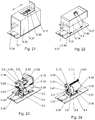
- FIG. 21-26 there is illustrated an alternative motion imparting leg 3, which is similar to the leg 1 of Fig 5-12 , with the exception of the actuator mechanism which uses a timing pulley gear reducer.
- the motion imparting leg 3 comprises a flat base 3.1 which is connected to a rectangular pipe 3.2, that accommodates internally the motion imparting actuator mechanism and a motion supportive structure.
- the connection between the flat base 3.1 and the rectangular pipe 3.2 comprises the bars 3.3 which accommodate for each bar 3.3 two buried screws 3.31 into the rectangular pipe 3.2, and one buried screw 3.31 into the flat base 3.1.
- the motion imparting mechanism comprise an electric motor 3.6 which is mounted on a L shape support structure 3.5, a timing pulley gear reducer which includes a timing pulley 3.7 mounted on the motor 3.6 shaft, a timing belt 3.13, and a second timing pulley 3.12 mounted on the shaft of the leadscrew rod 3.11.
- the timing pulley 3.7 is secured on the motor shaft by the screw 3.41
- a second timing pulley 3.12 is secured to the shaft of the leadscrew rod 3.11, by the screw 3.28.
- the motor 3.6 is mounted using four screws 3.30 on the L shape support structure 3.5 which is mounted on the flat base 3.1 using four screws 3.33, four nuts 3.35 and four washers 3.46.
- the L shape support structure 3.5 lies between two layers of rubber 3.4, one underneath rubber layer 3.4 that reduces the motor 3.6 vibration towards the flat base 3.1, and an upper rubber layer 3.4 which reduces the motor 3.6 vibration towards the four washers 3.46, the screws 3.33, and the four nuts 3.35.
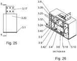
- the leadscrew rod 3.11 is supported at both ends by the bearings 3.43. These bearings are accommodated and secured by the U shape support structure 3.42. The motion is imparted in a horizontal plane along the axis of the two supporting rods 3.8, by the transformation of the rotary motion of the leadscrew rod 3.11 into a linear motion induced to the moving block 3.10.
- the moving block 3.10 includes a nut threading which accommodates the leadscrew rod 3.11, two cylindrical housings for the linear bearings 3.9, and seven threaded holes which accommodate the screws 3.27, 3.36, 3.37 and 3.45.
- the linear bearings 3.9 slide along with the moving block 3.10 on the two supporting rods 3.8, in accordance with the motion induced by the leadscrew rod 3.11.
- the supporting rods 3.8 are fastened on both sides against the U shape support structure 3.42 and the leg rectangular pipe 3.2 by the screws 3.14.
- the L shape support structure 3.40 supports as well the rods 3.8, and the first is connected to the U shape support structure 3.42 through the screws 3.38.
- the leadscrew rod 3.11 passes unobstructed through the L shape support structure 3.40.
- the end of the oscillatory motion path is detected electronically by the means of two switches “single-pole, single-throw” (on or off) 3.18 which are mounted on the U shape support structure 3.42.
- switches 3.18 On the lower side of the moving block 3.10 there are two perpendicular flat boards 3.19 arranged on opposite sides, that trigger the switches 3.18 when the moving block 3.10 reaches either end of the motion path.
- the switches 3.18 may be used only for the first round that the rocking apparatus imparts an oscillating motion.
- the subsequent oscillating motions don't need to use the switches 3.18 to detect the end of the movement path, as the control logic of the motion control unit 6 ( Fig. 1 ) stores in its memory the location of the switches 3.18. More information regarding the switches logic will be included further down in the motion control and communication unit 6 description.
- the motor 3.6 electric cables and the switches 3.18 electric cables are protected by a housing 3.24 ( Fig. 21 ) which is mounted on the flat base 3.1.
- the housing 3.24 is secured against the flat base 3.1 using two screws 3.32, and shields the electric cables against being tangled by the decorative housing 3.20.
- the frame supporting structure 3.39 is mounted on the moving block 3.10 using the screws 3.27, 3.36, 3.37 and 3.45.
- the flat sheet 3.16 is welded to the frame supporting structure 3.39 in order to increase the last mechanical resistance.
- the decorative housing 3.20 wraps and hides the frame supporting structure 3.39 and the internal leg mechanism. As shown in Fig 25 , there is no physical contact between the decorative housing 3.20 and the leg lower side which includes the flat base 3.1, the electric cables housing 3.24, and the rectangular pipe 3.2.
- the oscillatory motion is imparted in a horizontal plane to the moving block 3.10, to the connected supporting structure 3.39, to the decorative housing 3.20, to the linkage assembly 3.17 and to the bolt 3.21.
- the bolt 3.21 is rigidly mounted on the frame supporting structure 3.39 and passes through the decorative housing 3.20.
- the bolt 3.25 is mounted onto the U shape support structure 3.42 using the nut 3.26 and passes unobstructed through the frame supporting structure 3.39 and the decorative housing 3.20. There is no physical contact between the bolt 3.25 and the frame supporting structure 3.39, and neither the decorative housing 3.20.
- the bolt 3.21 is connected to the leg 3 moving apparatus and the bolt 3.25 is connected to the leg 3 static structure.
- One of the legs connecting rods that comprise the rod segment 4 may be screwed into the bolt 3.21 and tightened with the nut 4.1.
- the other connecting rod is screwed into the bolt 3.25.
- the connection between the motion imparting leg 3 and the passive leg 2 is done through connecting rod segments 4 and 5, which keep the legs mobile and static parts synchronized.
- the linkage assembly 3.17 ( Fig. 21 ) is tightened against the decorative housing 3.20 and the moving block 3.10 using the screws 3.36 and 3.37.
- the linkage assembly 3.17 comprise two parallel groove cuts which allow to adjust the linkage assembly 3.17 relative position against the decorative housing 3.20. By loosening the screws 3.36 and 3.37 the linkage assembly 3.17 may be moved inwards or outwards the leg's edge in order to match any bed frame width.
- the motion imparting leg 3 may replace the motion imparting leg 1 in any of the present invention embodiments.
- FIG. 27 it shows the electrical block schematic of the preferred embodiment of the modular rocking bed system.
- the last corresponds to the apparatus disclosed in the Figs. 1-3 and comprises two motion imparting legs 1, two passive legs 2, the motion control and communication unit 6, a data communication network 11, motion sensors 7, 16, a weight sensor 2.40, a passive infrared sensor (PIR) 16, a headband brain activity sensor 15, a wrist temperature, heart rate and blood pressure sensor 12, and a user terminal 13.
- the electrical parts of the motion imparting leg 1 are the motor 1.1 and two switches 1.22.
- the electrical parts of the passive leg 2 are the two switches 2.11.
- the motion control and communication unit 6 comprise two motor drivers 6.7, a network data communication module 6.2, a microcontroller 6.1, three potentiometers 6.3, 6.4, 6.5, and a switch 6.6.
- the motion control and communication unit 6 is connected to two motion imparting legs 1, two passive legs 2, two motion sensors 7, and the weight sensor 2.40.
- the weight sensor 2.40 may be part of a motion imparting leg 1, 3, or a passive leg 2. In this schematic it is part of the passive leg 2.
- the electric motors 1.1 are controlled by the motor drivers 6.7, that are part of the motion control and communication unit 6.
- the microcontroller 6.1 maintains the synchronization between the motors 1.1 through a motion control software. The last ensures that both motors 1.1 instantaneous speed and implicitly the relative distance between all the legs moving parts is maintained constant at any time.
- the oscillatory rocking motion is achieved by changing the motors 1.1 rotation sense at the end of the motion path.
- the last is bordered by the switches 1.22 and 2.11.
- the switches 1.22 detect the end of the motion paths for the legs 1 and the switches 2.11 detect the end of the motion path for the legs 2.
- the microcontroller 6.1 detects whether any of them is triggered on a given motion path, that imply the end of the motion path is reached.
- the motors 1.1 are stopped and the last rotation is reversed. Subsequently the rocking apparatus starts to move in the opposite direction until the switches 1.22 and 2.11 are triggered again at the other end of the motion path.
- the switches may be used only for the first round that the rocking apparatus imparts an oscillating motion. The subsequent oscillating motions don't need to use the switches to detect the end of the oscillation path, as the control logic of the motion control unit 6 stores in its memory the switches location.
- the motion control and communication unit 6 provides the basic user controls for the rocking motion system.
- the controls comprise the potentiometer 6.3 that controls the rocking speed, the potentiometer 6.4 that controls the amount of time after which the rocking motion ceases following a state of no motion from the motion sensors, the potentiometer 6.5 that controls the total expected sleep duration after which the rocking motion is disabled, and a switch 6.6 which forces the rocking motion activation or deactivation. Further details related to the user controls usage are explained in relation to Fig 29 .
- the user controls 6.3, 6.4, 6.6 may be overridden by an application which runs on the terminal 13, along with other user customized controls.
- the application that runs on the terminal 13 may include a sleep tracking functionality, and a database that contains the history of the sleep and the motion related data over a period of time.
- the motion sensors 7, 16, along with the temperature, heart rate, blood pressure sensor 12, and the brain activity sensor 15 are used to track the user status, in relation to sleep and alertness.
- the weight sensor 2.40 uses a method which measures the differential of the total bed weight over time, and based on that detects whether the user lies or not on the bed. This information along with the user settings is used for starting and stopping the rocking motion in an automated way.
- the present invention doesn't limit the type of sensors which may be used for tracking the user status. Further details regarding the relation between the information provided by the motion, temperature, heart rate, blood pressure and weight sensors, and the induced rocking motion are explained in relation to Fig. 29 .
- Fig. 28 shows the electrical block schematic of the second embodiment of the modular rocking bed system.
- the last corresponds to the apparatus disclosed in the Fig. 4 and comprise four motion imparting legs 1, the motion control and communication unit 6, a data communication network 11, motion sensors 7, a weight sensor 2.40, a passive infrared sensor (PIR) 16, a headband brain activity sensor 15, a wrist temperature, heart rate and blood pressure sensor 12, and a user terminal 13.
- the motion control and communication unit 6 comprise four motor drivers 6.7, one corresponding to each of the motion imparting leg motors 1.1.
- the microcontroller 6.1 maintains the synchronization between the motors 1.1 through a motion control software. The last ensures that all the four motors 1.1 instantaneous speed and implicitly the relative distance between the legs moving parts is maintained constant at any time.
- the remaining blocks and system functionality in Fig. 28 is identical to the one described in relation to Fig. 27 .
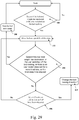
- the method detects whether the bed total weight has increased or the user 14 switches on manually the bed rocking movement using the switch 6.6 (100).
- bed total weight as used throughout the specification imply the sum of the bed and the user weights.
- the bed total weight is monitored by the weight sensor 2.40, and the assumption is that when the user 14 lies on the bed 9, the last total weight increases. This triggers the notification that the user lies on the bed and afterward, the bed starts to move on a predefined direction, which imply that all the motion imparting legs will start to push the bed in the same direction (102).
- the method detects whether the bed total weight has decreased, or the user switched off manually the bed rocking using the switch 6.6, or there is no user motion detected using the motion sensors 7, 16 for a predefined time set by the potentiometer 6.4, or the total desired sleep time set by the potentiometer 6.5 elapsed (104). If not so, the method detects further whether any of the switches 1.22 or 2.11 or 3.18 have been triggered (106). The switches are triggered at the end of the current moving direction path which imply that the moving direction has to be changed (110). The switches index 1.22, 2.11 and 3.18 correspond to all the possible legs 1 or 2 or 3 that could be part of the rocking apparatus. It is understood that depending on a particular instantiation, some of the switches 1.22, 2.11 or 3.18 might not be part of the system.
- the method executes the bed 9 rocking motion by looping back to state (102) until any of the conditions in state (104) are true. In that case the bed stops the movement (108) and gets back into the mode (100).
- the flowchart discloses a simplified rocking bed state machine that doesn't cover complex scenarios which imply and are not limited to user defined controls, motion or oscillation patterns which use the information provided by motion sensors 7, 16, temperature, heart rate and blood pressure sensors 12, brain activity sensors 15, or settings from an application running on a control terminal 13.
- Another important method for controlling the bed 9 rocking motion characteristics consists in using the periodicity and level information of the wave signals that are captured by one or more brain activity sensors 15, for setting and synchronizing the bed 9 oscillatory motion periodicity and speed.
Landscapes
- Invalid Beds And Related Equipment (AREA)
Priority Applications (5)
| Application Number | Priority Date | Filing Date | Title |
|---|---|---|---|
| EP16197183.3A EP3318162A1 (fr) | 2016-11-03 | 2016-11-03 | Lit basculant modulaire à commande programmable |
| CN201780064665.0A CN110062591B (zh) | 2016-11-03 | 2017-11-02 | 具有可编程控制器的模块化摇床 |
| US16/346,186 US20190290011A1 (en) | 2016-11-03 | 2017-11-02 | Modular rocking bed with programmable control |
| PCT/EP2017/078014 WO2018083153A1 (fr) | 2016-11-03 | 2017-11-02 | Lit modulaire à balancement et à commande programmable |
| EP17801618.4A EP3534755A1 (fr) | 2016-11-03 | 2017-11-02 | Lit modulaire à balancement et à commande programmable |
Applications Claiming Priority (1)
| Application Number | Priority Date | Filing Date | Title |
|---|---|---|---|
| EP16197183.3A EP3318162A1 (fr) | 2016-11-03 | 2016-11-03 | Lit basculant modulaire à commande programmable |
Publications (1)
| Publication Number | Publication Date |
|---|---|
| EP3318162A1 true EP3318162A1 (fr) | 2018-05-09 |
Family
ID=57240948
Family Applications (2)
| Application Number | Title | Priority Date | Filing Date |
|---|---|---|---|
| EP16197183.3A Withdrawn EP3318162A1 (fr) | 2016-11-03 | 2016-11-03 | Lit basculant modulaire à commande programmable |
| EP17801618.4A Withdrawn EP3534755A1 (fr) | 2016-11-03 | 2017-11-02 | Lit modulaire à balancement et à commande programmable |
Family Applications After (1)
| Application Number | Title | Priority Date | Filing Date |
|---|---|---|---|
| EP17801618.4A Withdrawn EP3534755A1 (fr) | 2016-11-03 | 2017-11-02 | Lit modulaire à balancement et à commande programmable |
Country Status (4)
| Country | Link |
|---|---|
| US (1) | US20190290011A1 (fr) |
| EP (2) | EP3318162A1 (fr) |
| CN (1) | CN110062591B (fr) |
| WO (1) | WO2018083153A1 (fr) |
Cited By (2)
| Publication number | Priority date | Publication date | Assignee | Title |
|---|---|---|---|---|
| DE102020100054A1 (de) * | 2020-01-03 | 2021-07-08 | Robert REIZ | Vorrichtung zum Bewegen eines Kinderbetts |
| US12290178B2 (en) | 2021-08-18 | 2025-05-06 | Adiva Wellness Srl | Rocking legs for a bed |
Families Citing this family (12)
| Publication number | Priority date | Publication date | Assignee | Title |
|---|---|---|---|---|
| DE102019131239A1 (de) * | 2019-11-19 | 2021-05-20 | Frank Krause | Verfahren zum Bewegen einer Bettoberfläche, ein Bettgestell, ein Lattenrost, eine Matratze und ein Steuerpanel |
| CN111053659B (zh) * | 2020-01-16 | 2024-08-27 | 赵自健 | 保健型摇床 |
| RU2020110924A (ru) * | 2020-03-16 | 2021-09-16 | Илья Ефимович Воронин | Укачивающий матрас |
| WO2021263199A2 (fr) * | 2020-06-25 | 2021-12-30 | Brigham Young University | Dispositif et procédé d'induction de formes d'onde de vibration qui s'hétérodynent dans le corps pour améliorer l'apparition du sommeil et la qualité du sommeil |
| US11812858B1 (en) | 2020-08-19 | 2023-11-14 | Clay Plemmons | Programmable rocking bed |
| CN112826676A (zh) * | 2021-01-09 | 2021-05-25 | 刘小芳 | 一种儿科护理智能摇床 |
| JP2022139679A (ja) * | 2021-03-12 | 2022-09-26 | パラマウントベッド株式会社 | ベッド用脚座およびベッド |
| US11696651B2 (en) | 2021-06-10 | 2023-07-11 | Ryan Taylor Manwaring | Crib conversion devices for enabling bouncing motion |
| WO2023195936A1 (fr) * | 2022-04-07 | 2023-10-12 | Eli̇t Dayanikli Tüketi̇m Mallari Gida İnş. İç Ve Diş. Ti̇c.Ltd.Şti̇. | Système de moteur dans un berceau pour bébé à balancement vertical |
| ES1305082Y (es) * | 2023-10-19 | 2024-04-09 | Munoz Jaime De Los Reyes Morales | Dispositivo de balanceo de un soporte para bebes |
| GB2637011A (en) * | 2024-01-03 | 2025-07-09 | Inoveris Solutions Srl | System and methods for improving sleep quality |
| GB2641003A (en) * | 2024-01-04 | 2025-11-19 | Inoveris Solutions Srl | A motion imparting leg for rocking a bed |
Citations (12)
| Publication number | Priority date | Publication date | Assignee | Title |
|---|---|---|---|---|
| US3934283A (en) | 1974-06-17 | 1976-01-27 | Raffel Marvin J | Bed frame with readily connectable vibrator motors |
| US4793010A (en) | 1987-10-28 | 1988-12-27 | General Ideas & Products Ltd. | Baby rocker apparatus |
| FR2649872A1 (fr) * | 1989-05-11 | 1991-01-25 | Canovas Gines | Dispositif pour bercer les jeunes enfants |
| EP0420065A2 (fr) * | 1989-09-29 | 1991-04-03 | Infant Advantage, Inc. | Système et méthode de transition environnante pour nouveau-né |
| DE29710002U1 (de) * | 1997-06-09 | 1997-09-04 | Olsen Joerg Dipl Betriebsw | Kinderwagen |
| US6068566A (en) * | 1997-12-31 | 2000-05-30 | Kim; Do Hyong | Device for driving a childcare apparatus for infants |
| WO2005084497A1 (fr) | 2004-03-08 | 2005-09-15 | Mitchell Christopher Robert Mu | Appareil de balancement pour lit d'enfant |
| US20070094792A1 (en) | 2005-10-31 | 2007-05-03 | Sims Dewey M Jr | Variable motion rocking bed |
| EP1900311A1 (fr) | 2006-09-12 | 2008-03-19 | Makeridea S.r.l. | Appareil pour la vibration d'un lit de camp, d'un berceau ou similaires |
| ES2383364A1 (es) * | 2010-10-27 | 2012-06-20 | Universidad De Valladolid | Dispositivo de acunado automático |
| US8856982B1 (en) | 2010-07-13 | 2014-10-14 | Christopher George Kalivas | Motion bed |
| US20150250329A1 (en) * | 2014-03-04 | 2015-09-10 | LeRahn Murray | Bassinet apparatus |
Family Cites Families (9)
| Publication number | Priority date | Publication date | Assignee | Title |
|---|---|---|---|---|
| FR1103398A (fr) * | 1954-07-02 | 1955-11-02 | Mécanisme pour communiquer un mouvement de va-et-vient à des berceaux et voitures similaires | |
| US2888086A (en) * | 1957-09-06 | 1959-05-26 | Daniel C O'brien | Carriage oscillating device |
| CN2087461U (zh) * | 1990-06-15 | 1991-10-30 | 秦皓 | 婴儿床、童车自动摇晃底盘 |
| DE19841592A1 (de) * | 1998-09-11 | 2000-03-23 | Knappe Dietmar | Vorrichtung zum Hin- und Herschieben eines Kinderwagens |
| TW463751U (en) * | 2000-06-09 | 2001-11-11 | Chen Jeng Yi | The recycle system with electronic of baby car |
| CN2500180Y (zh) * | 2001-09-14 | 2002-07-17 | 魏和斌 | 一种电动摇椅 |
| TWM360624U (en) | 2009-03-03 | 2009-07-11 | Ying-Su Zhong | Electric rocking bed and chair structures |
| CN204378607U (zh) * | 2015-01-30 | 2015-06-10 | 三峡大学 | 基于智能手机监控的电动婴儿摇床 |
| US10258761B2 (en) * | 2015-04-16 | 2019-04-16 | Graco Children's Products Inc. | Children's product with synchronized sound and non-sound output |
-
2016
- 2016-11-03 EP EP16197183.3A patent/EP3318162A1/fr not_active Withdrawn
-
2017
- 2017-11-02 CN CN201780064665.0A patent/CN110062591B/zh active Active
- 2017-11-02 WO PCT/EP2017/078014 patent/WO2018083153A1/fr not_active Ceased
- 2017-11-02 US US16/346,186 patent/US20190290011A1/en not_active Abandoned
- 2017-11-02 EP EP17801618.4A patent/EP3534755A1/fr not_active Withdrawn
Patent Citations (12)
| Publication number | Priority date | Publication date | Assignee | Title |
|---|---|---|---|---|
| US3934283A (en) | 1974-06-17 | 1976-01-27 | Raffel Marvin J | Bed frame with readily connectable vibrator motors |
| US4793010A (en) | 1987-10-28 | 1988-12-27 | General Ideas & Products Ltd. | Baby rocker apparatus |
| FR2649872A1 (fr) * | 1989-05-11 | 1991-01-25 | Canovas Gines | Dispositif pour bercer les jeunes enfants |
| EP0420065A2 (fr) * | 1989-09-29 | 1991-04-03 | Infant Advantage, Inc. | Système et méthode de transition environnante pour nouveau-né |
| DE29710002U1 (de) * | 1997-06-09 | 1997-09-04 | Olsen Joerg Dipl Betriebsw | Kinderwagen |
| US6068566A (en) * | 1997-12-31 | 2000-05-30 | Kim; Do Hyong | Device for driving a childcare apparatus for infants |
| WO2005084497A1 (fr) | 2004-03-08 | 2005-09-15 | Mitchell Christopher Robert Mu | Appareil de balancement pour lit d'enfant |
| US20070094792A1 (en) | 2005-10-31 | 2007-05-03 | Sims Dewey M Jr | Variable motion rocking bed |
| EP1900311A1 (fr) | 2006-09-12 | 2008-03-19 | Makeridea S.r.l. | Appareil pour la vibration d'un lit de camp, d'un berceau ou similaires |
| US8856982B1 (en) | 2010-07-13 | 2014-10-14 | Christopher George Kalivas | Motion bed |
| ES2383364A1 (es) * | 2010-10-27 | 2012-06-20 | Universidad De Valladolid | Dispositivo de acunado automático |
| US20150250329A1 (en) * | 2014-03-04 | 2015-09-10 | LeRahn Murray | Bassinet apparatus |
Cited By (2)
| Publication number | Priority date | Publication date | Assignee | Title |
|---|---|---|---|---|
| DE102020100054A1 (de) * | 2020-01-03 | 2021-07-08 | Robert REIZ | Vorrichtung zum Bewegen eines Kinderbetts |
| US12290178B2 (en) | 2021-08-18 | 2025-05-06 | Adiva Wellness Srl | Rocking legs for a bed |
Also Published As
| Publication number | Publication date |
|---|---|
| US20190290011A1 (en) | 2019-09-26 |
| EP3534755A1 (fr) | 2019-09-11 |
| CN110062591B (zh) | 2022-03-15 |
| WO2018083153A1 (fr) | 2018-05-11 |
| CN110062591A (zh) | 2019-07-26 |
Similar Documents
| Publication | Publication Date | Title |
|---|---|---|
| EP3318162A1 (fr) | Lit basculant modulaire à commande programmable | |
| US8909357B2 (en) | System for tandem bed communication | |
| US5103511A (en) | Oscillatory bed | |
| US10064784B2 (en) | System and method of an adjustable bed with a vibration motor | |
| US8046115B2 (en) | Common control of an adjustable bed and a second system using stored preferences | |
| CA2789496C (fr) | Commande de position de lit reglable | |
| US20130289770A1 (en) | System and method of a bed with a safety stop | |
| US20130191992A1 (en) | Adjustable bed frame with mattress bracket | |
| WO2013173640A1 (fr) | Système et procédé pour un lit muni d'un mécanisme d'arrêt de sécurité | |
| KR101456388B1 (ko) | 승강 및 왕복이동 침상이 구비된 침대 | |
| CN109109956B (zh) | 婴儿车 | |
| CN111887666A (zh) | 一种智能婴儿床 | |
| US20180220805A1 (en) | Vibration motor assembly for bed facility | |
| JP2001340198A (ja) | 高低自動可変枕 | |
| KR870000712B1 (ko) | 전동 요람 | |
| UA135986U (uk) | Дитяче ліжко-колиска з інтелектуальною системою управління |
Legal Events
| Date | Code | Title | Description |
|---|---|---|---|
| PUAI | Public reference made under article 153(3) epc to a published international application that has entered the european phase |
Free format text: ORIGINAL CODE: 0009012 |
|
| AK | Designated contracting states |
Kind code of ref document: A1 Designated state(s): AL AT BE BG CH CY CZ DE DK EE ES FI FR GB GR HR HU IE IS IT LI LT LU LV MC MK MT NL NO PL PT RO RS SE SI SK SM TR |
|
| AX | Request for extension of the european patent |
Extension state: BA ME |
|
| STAA | Information on the status of an ep patent application or granted ep patent |
Free format text: STATUS: THE APPLICATION IS DEEMED TO BE WITHDRAWN |
|
| 18D | Application deemed to be withdrawn |
Effective date: 20181110 |