EP3318191B1 - System zum sammeln von blutproben von einem patienten und entsprechende probensammelvorrichtung und pumpen zur blutentnahme von einem patienten - Google Patents
System zum sammeln von blutproben von einem patienten und entsprechende probensammelvorrichtung und pumpen zur blutentnahme von einem patienten Download PDFInfo
- Publication number
- EP3318191B1 EP3318191B1 EP16750874.6A EP16750874A EP3318191B1 EP 3318191 B1 EP3318191 B1 EP 3318191B1 EP 16750874 A EP16750874 A EP 16750874A EP 3318191 B1 EP3318191 B1 EP 3318191B1
- Authority
- EP
- European Patent Office
- Prior art keywords
- needle
- support member
- blood
- pump
- lever
- Prior art date
- Legal status (The legal status is an assumption and is not a legal conclusion. Google has not performed a legal analysis and makes no representation as to the accuracy of the status listed.)
- Active
Links
Images


Classifications
-
- A—HUMAN NECESSITIES
- A61—MEDICAL OR VETERINARY SCIENCE; HYGIENE
- A61M—DEVICES FOR INTRODUCING MEDIA INTO, OR ONTO, THE BODY; DEVICES FOR TRANSDUCING BODY MEDIA OR FOR TAKING MEDIA FROM THE BODY; DEVICES FOR PRODUCING OR ENDING SLEEP OR STUPOR
- A61M5/00—Devices for bringing media into the body in a subcutaneous, intra-vascular or intramuscular way; Accessories therefor, e.g. filling or cleaning devices, arm-rests
- A61M5/14—Infusion devices, e.g. infusing by gravity; Blood infusion; Accessories therefor
- A61M5/142—Pressure infusion, e.g. using pumps
- A61M5/14212—Pumping with an aspiration and an expulsion action
- A61M5/14228—Pumping with an aspiration and an expulsion action with linear peristaltic action, i.e. comprising at least three pressurising members or a helical member
-
- A—HUMAN NECESSITIES
- A61—MEDICAL OR VETERINARY SCIENCE; HYGIENE
- A61B—DIAGNOSIS; SURGERY; IDENTIFICATION
- A61B5/00—Measuring for diagnostic purposes; Identification of persons
- A61B5/15—Devices for taking samples of blood
- A61B5/150007—Details
- A61B5/150206—Construction or design features not otherwise provided for; manufacturing or production; packages; sterilisation of piercing element, piercing device or sampling device
- A61B5/150267—Modular design or construction, i.e. subunits are assembled separately before being joined together or the device comprises interchangeable or detachable modules
-
- A—HUMAN NECESSITIES
- A61—MEDICAL OR VETERINARY SCIENCE; HYGIENE
- A61B—DIAGNOSIS; SURGERY; IDENTIFICATION
- A61B5/00—Measuring for diagnostic purposes; Identification of persons
- A61B5/15—Devices for taking samples of blood
- A61B5/150007—Details
- A61B5/150015—Source of blood
- A61B5/15003—Source of blood for venous or arterial blood
-
- A—HUMAN NECESSITIES
- A61—MEDICAL OR VETERINARY SCIENCE; HYGIENE
- A61B—DIAGNOSIS; SURGERY; IDENTIFICATION
- A61B5/00—Measuring for diagnostic purposes; Identification of persons
- A61B5/15—Devices for taking samples of blood
- A61B5/150007—Details
- A61B5/150206—Construction or design features not otherwise provided for; manufacturing or production; packages; sterilisation of piercing element, piercing device or sampling device
- A61B5/150229—Pumps for assisting the blood sampling
-
- A—HUMAN NECESSITIES
- A61—MEDICAL OR VETERINARY SCIENCE; HYGIENE
- A61B—DIAGNOSIS; SURGERY; IDENTIFICATION
- A61B5/00—Measuring for diagnostic purposes; Identification of persons
- A61B5/15—Devices for taking samples of blood
- A61B5/150007—Details
- A61B5/150206—Construction or design features not otherwise provided for; manufacturing or production; packages; sterilisation of piercing element, piercing device or sampling device
- A61B5/150259—Improved gripping, e.g. with high friction pattern or projections on the housing surface or an ergonometric shape
-
- A—HUMAN NECESSITIES
- A61—MEDICAL OR VETERINARY SCIENCE; HYGIENE
- A61B—DIAGNOSIS; SURGERY; IDENTIFICATION
- A61B5/00—Measuring for diagnostic purposes; Identification of persons
- A61B5/15—Devices for taking samples of blood
- A61B5/150007—Details
- A61B5/150351—Caps, stoppers or lids for sealing or closing a blood collection vessel or container, e.g. a test-tube or syringe barrel
-
- A—HUMAN NECESSITIES
- A61—MEDICAL OR VETERINARY SCIENCE; HYGIENE
- A61B—DIAGNOSIS; SURGERY; IDENTIFICATION
- A61B5/00—Measuring for diagnostic purposes; Identification of persons
- A61B5/15—Devices for taking samples of blood
- A61B5/150007—Details
- A61B5/150374—Details of piercing elements or protective means for preventing accidental injuries by such piercing elements
- A61B5/150381—Design of piercing elements
- A61B5/150503—Single-ended needles
-
- A—HUMAN NECESSITIES
- A61—MEDICAL OR VETERINARY SCIENCE; HYGIENE
- A61B—DIAGNOSIS; SURGERY; IDENTIFICATION
- A61B5/00—Measuring for diagnostic purposes; Identification of persons
- A61B5/15—Devices for taking samples of blood
- A61B5/150007—Details
- A61B5/150732—Needle holders, for instance for holding the needle by the hub, used for example with double-ended needle and pre-evacuated tube
-
- A—HUMAN NECESSITIES
- A61—MEDICAL OR VETERINARY SCIENCE; HYGIENE
- A61B—DIAGNOSIS; SURGERY; IDENTIFICATION
- A61B5/00—Measuring for diagnostic purposes; Identification of persons
- A61B5/15—Devices for taking samples of blood
- A61B5/150007—Details
- A61B5/150801—Means for facilitating use, e.g. by people with impaired vision; means for indicating when used correctly or incorrectly; means for alarming
- A61B5/150824—Means for facilitating use, e.g. by people with impaired vision; means for indicating when used correctly or incorrectly; means for alarming by visual feedback
-
- A—HUMAN NECESSITIES
- A61—MEDICAL OR VETERINARY SCIENCE; HYGIENE
- A61M—DEVICES FOR INTRODUCING MEDIA INTO, OR ONTO, THE BODY; DEVICES FOR TRANSDUCING BODY MEDIA OR FOR TAKING MEDIA FROM THE BODY; DEVICES FOR PRODUCING OR ENDING SLEEP OR STUPOR
- A61M5/00—Devices for bringing media into the body in a subcutaneous, intra-vascular or intramuscular way; Accessories therefor, e.g. filling or cleaning devices, arm-rests
- A61M5/178—Syringes
- A61M5/31—Details
- A61M5/32—Needles; Details of needles pertaining to their connection with syringe or hub; Accessories for bringing the needle into, or holding the needle on, the body; Devices for protection of needles
- A61M5/3205—Apparatus for removing or disposing of used needles or syringes, e.g. containers; Means for protection against accidental injuries from used needles
-
- A—HUMAN NECESSITIES
- A61—MEDICAL OR VETERINARY SCIENCE; HYGIENE
- A61B—DIAGNOSIS; SURGERY; IDENTIFICATION
- A61B2560/00—Constructional details of operational features of apparatus; Accessories for medical measuring apparatus
- A61B2560/02—Operational features
- A61B2560/0204—Operational features of power management
- A61B2560/0214—Operational features of power management of power generation or supply
-
- A—HUMAN NECESSITIES
- A61—MEDICAL OR VETERINARY SCIENCE; HYGIENE
- A61B—DIAGNOSIS; SURGERY; IDENTIFICATION
- A61B5/00—Measuring for diagnostic purposes; Identification of persons
- A61B5/15—Devices for taking samples of blood
- A61B5/150007—Details
- A61B5/150374—Details of piercing elements or protective means for preventing accidental injuries by such piercing elements
- A61B5/150381—Design of piercing elements
- A61B5/150389—Hollow piercing elements, e.g. canulas, needles, for piercing the skin
-
- A—HUMAN NECESSITIES
- A61—MEDICAL OR VETERINARY SCIENCE; HYGIENE
- A61B—DIAGNOSIS; SURGERY; IDENTIFICATION
- A61B5/00—Measuring for diagnostic purposes; Identification of persons
- A61B5/15—Devices for taking samples of blood
- A61B5/150007—Details
- A61B5/15074—Needle sets comprising wings, e.g. butterfly type, for ease of handling
-
- A—HUMAN NECESSITIES
- A61—MEDICAL OR VETERINARY SCIENCE; HYGIENE
- A61B—DIAGNOSIS; SURGERY; IDENTIFICATION
- A61B5/00—Measuring for diagnostic purposes; Identification of persons
- A61B5/15—Devices for taking samples of blood
- A61B5/153—Devices specially adapted for taking samples of venous or arterial blood, e.g. with syringes
-
- A—HUMAN NECESSITIES
- A61—MEDICAL OR VETERINARY SCIENCE; HYGIENE
- A61M—DEVICES FOR INTRODUCING MEDIA INTO, OR ONTO, THE BODY; DEVICES FOR TRANSDUCING BODY MEDIA OR FOR TAKING MEDIA FROM THE BODY; DEVICES FOR PRODUCING OR ENDING SLEEP OR STUPOR
- A61M5/00—Devices for bringing media into the body in a subcutaneous, intra-vascular or intramuscular way; Accessories therefor, e.g. filling or cleaning devices, arm-rests
- A61M5/178—Syringes
- A61M5/31—Details
- A61M5/32—Needles; Details of needles pertaining to their connection with syringe or hub; Accessories for bringing the needle into, or holding the needle on, the body; Devices for protection of needles
- A61M5/3205—Apparatus for removing or disposing of used needles or syringes, e.g. containers; Means for protection against accidental injuries from used needles
- A61M2005/3206—Needle or needle hub disconnecting devices forming part of or being attached to the hub or syringe body
-
- A—HUMAN NECESSITIES
- A61—MEDICAL OR VETERINARY SCIENCE; HYGIENE
- A61M—DEVICES FOR INTRODUCING MEDIA INTO, OR ONTO, THE BODY; DEVICES FOR TRANSDUCING BODY MEDIA OR FOR TAKING MEDIA FROM THE BODY; DEVICES FOR PRODUCING OR ENDING SLEEP OR STUPOR
- A61M2205/00—General characteristics of the apparatus
- A61M2205/14—Detection of the presence or absence of a tube, a connector or a container in an apparatus
-
- A—HUMAN NECESSITIES
- A61—MEDICAL OR VETERINARY SCIENCE; HYGIENE
- A61M—DEVICES FOR INTRODUCING MEDIA INTO, OR ONTO, THE BODY; DEVICES FOR TRANSDUCING BODY MEDIA OR FOR TAKING MEDIA FROM THE BODY; DEVICES FOR PRODUCING OR ENDING SLEEP OR STUPOR
- A61M2205/00—General characteristics of the apparatus
- A61M2205/33—Controlling, regulating or measuring
- A61M2205/3306—Optical measuring means
-
- A—HUMAN NECESSITIES
- A61—MEDICAL OR VETERINARY SCIENCE; HYGIENE
- A61M—DEVICES FOR INTRODUCING MEDIA INTO, OR ONTO, THE BODY; DEVICES FOR TRANSDUCING BODY MEDIA OR FOR TAKING MEDIA FROM THE BODY; DEVICES FOR PRODUCING OR ENDING SLEEP OR STUPOR
- A61M2205/00—General characteristics of the apparatus
- A61M2205/33—Controlling, regulating or measuring
- A61M2205/3379—Masses, volumes, levels of fluids in reservoirs, flow rates
-
- A—HUMAN NECESSITIES
- A61—MEDICAL OR VETERINARY SCIENCE; HYGIENE
- A61M—DEVICES FOR INTRODUCING MEDIA INTO, OR ONTO, THE BODY; DEVICES FOR TRANSDUCING BODY MEDIA OR FOR TAKING MEDIA FROM THE BODY; DEVICES FOR PRODUCING OR ENDING SLEEP OR STUPOR
- A61M2205/00—General characteristics of the apparatus
- A61M2205/58—Means for facilitating use, e.g. by people with impaired vision
- A61M2205/581—Means for facilitating use, e.g. by people with impaired vision by audible feedback
Definitions
- the invention relates to a system for taking blood samples from a patient.
- the invention also relates to a sampling device and to a pump for extracting blood from a patient.
- US 4.008.717 describes a small, portable, constant withdrawal device. It is connected to tubing, including a catheter, whose internal walls are coated with heparin. The catheter is inserted intravenously through a disposal needle into a subject such as a human being. The subject may then move about for a selected period when blood is being slowly withdrawn at a prescribed rate and collected in a container within a housing supporting the device. The collected blood may then be analyzed to permit the measurement of the integrated concentration of glucose, growth hormone or other material in blood.
- a portable microdiffusion chamber is incorporated between the indwelling catheter and the extra corporal tubing and is electrically connected through a sensor probe to an associated sensory responsive device.
- WO 02/058556 describes a micro-sized device attached to the earlobe of a patient, for periodic, repeated analyses of blood or for injection of medicine.
- the device comprises a motor for moving a needle into the skin portion of the patient and withdrawal of a minute amount of blood for analysis.
- the result of the analysis controls the supply of a medical agent through the needle, whereupon the needle is retracted.
- the device is rotated over an angle before the next sampling, so that the new sampling takes place at a untouched skin area.
- US 5.046.509 describes an improved blood sampling device, which includes a coupling device connected to a needle for receiving blood withdrawn from a patient.
- the coupling device includes first and second ports in flow communication with the needle and is adapted to conduct blood to either the first or second port.
- the first port includes an adapter sleeve which is adapted to receive a vacutainer-type blood storage device for storing blood samples taken from the patient.
- a microporous hydrophobic plug is positioned within the coupling device intermediate the first port and the needle for venting air which is trapped within the coupling device during the initial stages of the sampling operation.
- the second port is connected to the coupling device intermediate the plug and the needle and is adapted to receive a syringe for temporarily storing a first portion of blood withdrawn from the patient thereby to ensure that blood subsequently delivered to the vacutainer contains gases having relative partial pressures and activities of ionic species substantially equal to those of the patient's in vivo conditions.
- the sampling device additionally comprises a hypodermic needle with a connection base, the connection base being suitable for being mounted on the tubular portion.
- the support comprises a cylindrical upper portion with a connector therein, where the cylindrical upper portion preferably has a plurality of openings.
- the support is made from a transparent material.
- the support member comprises at least two semi-cylindrical walls extending from the cylindrical upper portion, spaced apart by respective lateral openings, and very preferably it has four walls semi-cylindrical mutually separated by four lateral openings.
- the connector comprises an end portion suitable for connection in fluid communication with the tubular portion.
- it is particularly advantageous that it comprises attachment means suitable for retaining the needle holder in the support member.
- the device comprises retaining means of the flexible tube.
- the head member comprises an upper, horizontal U-shaped engagement portion and a lower portion having a smaller cross section than the upper portion.
- the head member comprises a sample holder tube presence sensor, a filling level sensor and/or a filling speed sensor.
- the head member comprises spring retaining means of the support.
- the pump comprises means for positioning the fixed surface relative to the moving surface suitable for moving the fixed surface between a spaced apart position and a pumping position, where the positioning means comprise reversible snap fitting means suitable for reversibly fixing the fixed surface relative to the pumping surface, and spring means urging said fixed surface to the spaced apart position.
- the pump comprises electronic control means and a data viewing screen.
- the system preferably comprises a sampling device according to the invention, as described below.
- the system preferably comprises a pump for extracting blood according to the invention, as described below.
- a pump for extracting blood from a patient characterized in that it is a peristaltic pump having a rotor, comprising at least one moving pumping surface and one fixed pumping surface, suitable for lodging therebetween a flexible tube, where the pump additionally comprises a head member suitable for the attachment of a sample holder tube support member.
- a peristaltic pump such as the indicated one for the extraction of blood from a patient offers a plurality of advantages:
- the head member comprises an upper, horizontal U-shaped engagement portion and a lower portion having a smaller cross section than the upper portion.
- the semicircular portion of the U defines a longitudinal axis which, under the normal conditions of use of the pump, is preferably positioned vertically. After the sample holder tube support member with the corresponding sample holder tube has been mounted, the axis of the sample holder tube coincides with the longitudinal axis.
- the thus defined upper engagement portion allows for simple, effective assembly and disassembly of the sample holder tube support member, which moves along the arms of the U until it reaches the semicircular portion.
- the smaller cross section of the lower portion serves to hold the support member and to prevent it falling downwardly.
- the filling level sensor and the filling speed sensor can share one same optical sensor.
- the optical sensor can discern between a falling drop and the full tube, since the full tube is much more opaque than a drop. Therefore, it is possible to distinguish between both phenomena with a single sensor.
- the predetermined blood volume can be electronically metered, as can the extraction speed be programmed, the pump being automatically stopped when the programmed amount has been metered, giving a particular acoustic signal.
- the head member preferably comprises retaining spring means for the support member.
- These spring means are advantageously protuberances projecting out from the arms of the U (and are orientated towards the inside of the U), in such a way that when the support member passes over them they retract and once the tube is in its definitive position, they extend again, (reversibly) retaining the support member in its position of use. In this way, the tube is prevented from being able to come out of its position of use undesirably, but it may be manually ejected, simply by overcoming the resilient force of the spring means.
- the pump preferably comprises positioning means for the fixed surface relative to the moving surface suitable for moving the fixed surface between a spaced-apart position, suitable for removing or positioning the flexible tube in the pump, and a pumping position.
- positioning means allow the pump to be "opened” (when separating the moving surface from the fixed surface) and “closed” (when joining both pumping surfaces together. With the pump open, the flexible tube may be removed and replaced with a new one in an extremely simple way.
- the positioning means advantageously comprise reversible snap-fitting means for reversibly fixing the fixed surface relative to the pumping surface, and spring means urging said fixed surface to the spaced-apart position.
- the reversible snap fitting enormously simplifies the operation of "opening” and “closing” the pump, such that the operation of replacing the flexible tube may be done in a few seconds, without needing any special tool or specific knowledge or training.
- the pump preferably comprises electronic control means and a data viewing screen.
- a sampling device characterized in that it comprises: [a] a needle holder having a tubular portion suitable for supporting a hypodermic needle having a connection base, said needle holder comprising a conduit with an inlet and an outlet, where said inlet comprises said tubular portion, [b] a sample holder tube support member and [c] a flexible tube having a first end in fluid communication with said needle holder and a second end in fluid communication with said support member.
- This whole device is replaced with a new one for each patient. It is therefore a consumable of a disposable kit, which may be used with the pump according to the invention.
- a security mechanism is connected to a self-sealing stopper therein allowing the air to pass for filling said device with simple venous pressure.
- the sampling device preferably comprises, in addition, a hypodermic needle having a connection base, said connection base being suitable for being mounted on said tubular portion.
- a hypodermic needle having a connection base, said connection base being suitable for being mounted on said tubular portion.
- the needle could come separately, it is more convenient for the user if the needle comes already mounted in the needle holder.
- the needle holder advantageously comprises an abutment surface and lever means suitable for separating the needle from the needle holder, the lever means comprising a lever having a first end suitable for being moved with a finger and a second end disposed between the connection base and the abutment surface.
- the needle holder advantageously comprises, furthermore, other improvements, such as for example:
- the needle connection base that comprises lever means suitable for separating the needle from the needle holder and the needle holder comprises an abutment surface, the lever means comprising a lever having a first end suitable for being moved with a finger and a second end disposed between the connection base and the abutment surface.
- the lever means are preferably integrally attached to the connection base.
- the sampling device comprises lever means suitable for separating the needle from the needle holder which form an independent part with attachment means suitable for attaching the independent part to the tubular portion and between the connection base and the abutment surface, where the needle holder comprises an abutment surface and where the lever means comprise a lever having a first end suitable for being moved with a finger and a second end disposed between the connection base and the abutment surface.
- attachment means are preferably a ring or a horseshoe-shaped protuberance.
- the lever is preferably rotatably attached to the needle holder, to the connection base or to the ring at an intermediate point, where the lever forms an angle of more than 45° with the needle axis, advantageously more than 70°.
- the tubular portion preferably defines a Luer connection according to ISO 594.1986, DIN 1707:1996 or DIN 20594-1:1993.
- the support member advantageously comprises a cylindrical upper portion having a connector in the interior thereof.
- the cylindrical upper portion is thus particularly suitable for engaging the upper, horizontal U-shaped engagement portion of the head member of the pump according to the invention.
- the inner connector allows for connection to the sample holder tube.
- the cylindrical upper portion to have a plurality of openings, through which the light of a sample holder tube presence sensor can propagate.
- the support member is made from a transparent material. When indicating 'transparent", it must be understood to be transparent at least for the frequency of the light emitted by the corresponding sensor.
- the support member preferably comprises at least two semi-cylindrical walls extending from the cylindrical upper portion, spaced apart by respective lateral openings, and very preferably it has four walls semi-cylindrical separated by four lateral openings. In fact, the presence of the lateral openings allows the support member to be positioned in the head member in a pre-established position, such as will be seen in the embodiments described hereinafter.
- the connector disposed in the interior of the cylindrical upper portion of the support member advantageously comprises an end portion suitable for connection in fluid communication with the tubular portion.
- the tube still contains blood. It is therefore necessary to contemplate a way of preventing this blood from representing a risk.
- the proposed solution allows the tubular portion of the needle holder to be connected to the end portion of the connector, thanks to which a closed circuit is formed in such a way that the blood preset in the flexible tube no longer flows out of it. In this way the used sampling device may be deposited in any conventional container, without any risk of spilling blood.
- the sampling device preferably comprises attachment means suitable for retaining the needle holder in the support member.
- attachment means suitable for retaining the needle holder in the support member.
- these attachment means comprise a groove disposed in the lever means. This groove may form an interference fit with the semi-cylindrical walls, as will be appreciated more clearly when explaining hereinafter embodiments of the invention.
- the sampling device advantageously comprises means for retaining the flexible tube such that the flexible tube does not move relative to the pump when the pump is pumping the blood.
- the flexible tube may comprise a ring disposed therearound at a pre-established position and fixed thereto and the pump may have a guide through which the naked tube, but not the ring, can pass.
- these flexible tube retaining means also act as means for the correct positioning of the flexible tube, thereby preventing the position from being reversed.
- a functional security means is included in the assembly preventing the pump from aspirating in a direction opposed to the right one.
- a hypodermic needle having a connection base characterized in that it comprises an ejection device integrally attached to the connection base, where the ejection device comprises lever means provided with a lever having a first end suitable for being moved with a finger and a second end in the proximity of the connection base.
- the lever means preferably include at least one of the other preferred solutions described in the present specification.
- a syringe comprising a hollow cylindrical body having a front wall, closed except for an outlet orifice from which a tubular portion extends, and a plunger suitable for traversing the interior of the hollow cylindrical body, characterized in that it comprises an ejection device integrally attached to the front wall, where the ejection device comprises lever means provided with a lever having a first end suitable for being moved with a finger and a second end in the proximity of the tubular portion.
- the lever means preferably include at least one of the other preferred solutions described in the present specification.
- a needle holder comprising a conduit having an inlet and an outlet, where the inlet comprises a tubular portion, characterized in that it comprises an ejection device integrally attached to the needle holder, where the ejection device comprises lever means provided with a lever having a first end suitable for being moved with a finger and a second end in the proximity of the tubular portion.
- the lever means preferably include at least one of the other preferred solutions described in the present specification.
- the fact of having said lever means allows ejecting the hypodermic needle in a very simple way, without the risk of being pricked and without the need for special containers and/or protectors.
- the user holds the syringe or needle holder (or, in general, any holder device having a tubular portion on which it must be possible to mount the connection base of the syringe) in the hand in the same position as in which the needle had been withdrawn from the patient's body such that the needle tip remains remote from the hand.
- the operator moves the first end of the lever and the second end exerts the force required for separating the connection base from the abutment, thereby ejecting the needle from the carrying device.
- the user Prior to performing this ejection movement with his or her finger, the user directs the tip of the needle towards a container for sharp-edged objects (which may be fully conventional in accordance with the current regulations) and on performing the ejection movement, the needle is projected towards the container. At all times the user's hand is behind the needle tip and the user's other hand should not participate in any way in the ejection procedure. Thus, the risk of being pricked is totally eliminated; the container may be a completely conventional container in keeping with current regulations, i.e. not having any special features for the ejection of the needle.
- the hypodermic needle comprises always a fine tube with a sharp tip at one end (which is the one inserted into the patient's body) and with the other end integrated in a connection base.
- the connection base allows the needle to be connected to any carrying device, such that there is established a fluid connection between the inside of the needle and the inside of the tubular portion of the carrying device.
- any type of connection may be established between the connection base and the tubular portion, with the sole limitation that it must be a reversible connection when applying a force tending to separate the connection base from the tubular portion, since this will be the force which is exerted by the lever.
- the tubular portion preferably defines a Luer connection according to ISO 594.1986, DIN 1707:1996 or DIN 20594-1:1993.
- Luer connections are widely used, whereby the ejection device according to the invention may advantageously be applied to hypodermic needles having a Luer type connection.
- lever means may be integrally attached to the carrying device or they may be integrally attached to the connection base.
- the carrying device and the connection base are usually made from plastics materials, it is advantageous for the lever means to form an integral unit with the carrying device or with the connection base, directly obtainable from the plastics injection mould.
- the lever means may also advantageously be an independent part having attachment means suitable for attaching the independent part to the tubular portion between the connection base and the abutment surface. These attachment means are preferably a ring or a horseshoe-shaped protuberance.
- the carrying device may be any one; the sole limitation being that it must have a tubular portion on which to be able to mount the connection base.
- various preferred embodiments of the invention may be obtained:
- the lever it is advantageous for the lever to be rotatably attached to the carrying device, to the syringe, to the needle holder, to the connection base or to the ring at an intermediate point, where the lever forms an angle of more than 45°with the axis of the needle, preferably more than 70°.
- the first end of the lever protrudes noticeably away from the carrying device and the connection base, such that it is easily accessible for the finger.
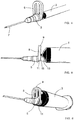
- FIG. 1 to 4 there is shown a first embodiment of an ejection device for a hypodermic needle 1 suitable for ejecting the hypodermic needle 1 from a carrying device 3 for the hypodermic needle 1 according to the invention.
- the hypodermic needle 1 has a connection base 5 and a tube 7 having a sharp-pointed end.
- the ejection device is integrally attached to the connection base 5.
- the ejection device is provided with lever means having a lever 8 which is attached to the connection base 5.
- the lever 8 has a first end 9 remote from the connection base 5 and a second end 111 which is disposed between the connection base 5 and the front wall 13 of the carrying device 3 which, in this particular case, is a conventional syringe.
- the syringe has a hollow cylindrical body with a front wall 13 having an outlet orifice from which there extends a tubular portion 15 (not visible in Figures 1 to 4 , but visible, for example, in Figure 5 ) on which the connection base 5 of the needle 1 is mounted.
- the front wall 13 acts as an abutment surface 17.
- the lever means the lever 8 has the general form of an inverted U having a transverse partition 9 which connects the arms of the U at an intermediate point.
- the lever means are attached to the connection base 5 through this partition 19, such that they may rock about the joint area between the connection base 5 and the partition 19.
- the user of the syringe to eject the hypodermic needle 1 from the syringe, has only to move the first end 9 of the lever 8 in a forward direction (namely, push it with a finger to separate it from the syringe) in this way the second end 11 moves towards the front wall 13 of the syringe and urges the connection base 5 in an outward direction.
- the needle 1 may be easily ejected.
- FIGS 5 and 6 there is shown a second embodiment of an ejection device for a hypodermic needle.
- the transverse partition 19 is attached to the front wall 13 of the syringe. Therefore, in this case, to eject the needle 1, the user must push the first end 9 in a backward direction. Thus, the second end 11 will move in a forward direction and will eject the needle 1. It is of particular interest when using syringes with an eccentric cone.
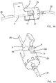
- Figure 7 shows a third embodiment of an ejection device for a hypodermic needle 1.
- the needle carrying device 3 for the hypodermic needle 1 is not a syringe, but is a needle holder.
- the needle holder has a conduit with an inlet 21 and an outlet 23.
- the inlet 21 defines a tubular portion 15 on which the needle 1 is mounted.
- the outlet 23 is connected to a flexible tube 25 allowing the extracted blood to be taken to wherever corresponds.
- the needle holder comprises, additionally, a flattened tab 27 extending from one of the sides of the conduit, serving to be held with the fingers.
- the needle holder is also provided with an ejection device consisting of lever means such as those already described.
- the transverse partition 19 is attached to the front wall 13 of the needle holder, which performs the function of abutment surface 17.
- the needle holder is clearly asymmetrical, in the sense that the user may hold it with two fingers by way of the tab 27 and can position the needle 1 very tangentially relative to the patient's skin.
- Figure 8 shows another embodiment of an ejection device according to the invention.
- the ejection device is an independent part having a ring which is disposed on the tubular portion 15 of the syringe between the connection base 5 of the needle 1 and the front wall 13 of the syringe defining the abutment surface 17.
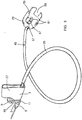
- FIG 9 there is shown a sampling device according to the invention.
- the sampling device comprises a flexible tube 25 having connected thereto at a first end a needle holder such as the one shown in Figure 7 and at the opposite end a support member 29 for sample holder tubes.
- the sampling device also includes a hypodermic needle 1 and an ejection device having lever means such as those described hereinbefore.
- a pump for extracting blood from a patient comprises a peristaltic pump having a rotor 31 provided with a moving pumping surface 33 (with the lobes characteristic of a peristaltic pump) and a fixed pumping surface 35.
- the pump also has a head member 37 (see Figure 15 ) suitable for attachment of a support member 29 of a sample holder tube.
- the pump has a chassis in which both the peristaltic pump and the head member 37 are attached. Nevertheless, in the figures the peristaltic pump and the head member 37 are shown separated from the pump chassis.
- the pump also has positioning means for the fixed surface 35 relative to the moving surface 33 suitable for moving the fixed surface 35 between a spaced apart position (see Figure 10 , the positioning means are in the "open” position), in which the fixed surface 35 is spaced apart from the moving surface 33 and a pumping position (see Figure 11 , the positioning means are in the "closed” position), in which the fixed surface 35 is in the proximity of the moving surface 33, i.e. it is at the appropriate distance to be able to perform the pumping function.
- the positioning means When the positioning means are in the open position, there is positioned between both pumping surfaces 33 and 35 the flexible tube 25 in such a way that when the positioning means are in a closed position the flexible tube 25 is compressed between both and the function of pumping or of a seal (preventing the blood from flowing out under the venous pressure itself) may be performed.
- the pump has two buttons 39 for operating the reversible snap fit means.
- buttons 39 When the buttons 39 are pressed, a metal strip is elastically deformed and thus there is released a step portion disposed on the fixed part of the pump which was lodged in a housing provided in the moving part of the pump.
- Spring means 41 (in the form of a spiral spring) urge the moving part of the pump (comprising the moving surface 33) towards the open position. To close the pump (for example, after positioning a new flexible tube 25), it is sufficient to push the moving part towards the fixed part until the step portion relodges itself in the housing.
- the pump has guide means 43 for the flexible tube 25 which also serve to hold the flexible tube 25 in a predetermined position thanks to the retaining means 45 disposed in the flexible tube 25 (in the form of a ring disposed on the flexible tube 25 and whose outer diameter is greater than the gap in the guide means 43.
- FIG 15 shows a head member 37 suitable for the attachment of a support member 29 for a sample holder tube.
- the head member 37 comprises an upper engagement portion 47, in the form of a horizontal U and a lower portion 49 having a cross section smaller than that of the upper portion.
- a step portion 51 which will prevent the support member 29 from moving in a downward direction (see Figure 17 ).
- the upper portion 47 is also provided with an upper step portion 53, such that the support member 29 cannot move in an upward direction either.
- Figure 16 shows a support member 29 for a sampling device according to the invention. It comprises a cylindrical upper portion 55 of the same size as the upper portion 47 of the engagement head member 37, such that it is suitable for being lodged in the interior of the upper engagement portion 47 by inserting it along the horizontal arms of the U (see Figure 17 ).
- the support member 29 has a connector 57 in the interior thereof, disposed coaxially with the cylindrical upper portion 55. Following the cylindrical upper portion 55, the cylindrical surface has four lateral openings 59, such that the cylindrical surface extends as four semi-cylindrical walls 61. Thus, when lining up the lateral openings 59, the support member 29 can be inserted in the head member 37 in a predefined position.
- FIG 17 there is shown the support member 29 lodged in the head member 37.
- the head member 37 has spring retaining means 63 for the support member 29 disposed in the upper engagement portion 47 and projecting out relative to the centre of the semi-circumference of the U in the direction of the arms of the U.
- the spring retaining means 63 are forced backwards and once the support member 29 is in its final position of use, then the spring retaining means 63 project once again towards the interior of the U, such that the support member 29 cannot come out of its final position without overcoming the force exerted by these spring retaining means 63.
- the support member 29 also has a plurality of openings 65 in the cylindrical upper portion 55.
- a presence sensor present in the head member 37 is situated facing two of these openings 65, such that a beam of light can pass through the support member 29.
- the stopper of the sample holder tube is disposed between the orifices 65, such that the beam of light emitted by the sensor cannot reach the corresponding receiver, thereby detecting the presence of the sample holder tube and preventing the pump from being started if there is no sample holder tube to collect the blood.
- the head member 37 may include a filling level sensor which is at the height of the lateral openings 59. In a way similar to the previous case, a beam of light passes through the sample holder tube, such that it may be detected when the blood level reaches the height of the corresponding sensor.
- the head member 37 may likewise include a filling speed sensor, which is also at the height of the lateral openings 59 and positioned just below the connector 57.
- a filling speed sensor which is also at the height of the lateral openings 59 and positioned just below the connector 57.
- FIG 20 there is shown the case in which the support member 29 has, at the end, a security mechanism 74, shown in Figure 20 as it was made from a transparent material, in order to be able to see that therein it has a self-sealing stopper (75).
- the self-sealing stopper (75) allows the air to pass for filling the device by simple venous pressure.
- FIGs 18 and 19 there is shown a sampling device with the needle holder mounted on the connector 57 of the support member 29.
- the connector 57 of the support member 29 has an end portion 67 which is suitable for engaging in the interior of the tubular portion 15.
- the lever means comprise attachment means, in the form of a groove 69, for guiding, which frictionally slides on the side edge 71 of the semi-cylindrical walls 61.
Landscapes
- Health & Medical Sciences (AREA)
- Life Sciences & Earth Sciences (AREA)
- Engineering & Computer Science (AREA)
- Public Health (AREA)
- Veterinary Medicine (AREA)
- Heart & Thoracic Surgery (AREA)
- Hematology (AREA)
- Biomedical Technology (AREA)
- Animal Behavior & Ethology (AREA)
- General Health & Medical Sciences (AREA)
- Pathology (AREA)
- Physics & Mathematics (AREA)
- Biophysics (AREA)
- Medical Informatics (AREA)
- Molecular Biology (AREA)
- Surgery (AREA)
- Manufacturing & Machinery (AREA)
- Vascular Medicine (AREA)
- Anesthesiology (AREA)
- Environmental & Geological Engineering (AREA)
- Measurement Of The Respiration, Hearing Ability, Form, And Blood Characteristics Of Living Organisms (AREA)
- Infusion, Injection, And Reservoir Apparatuses (AREA)
Claims (11)
- Blutprobenvorrichtung, die Folgendes umfasst: [a] einen Nadelhalter mit einem röhrenförmigen Abschnitt (15), der zum Stützen einer Injektionsnadel (1) mit einer Verbindungsbasis (5) geeignet ist, wobei der Nadelhalter eine Leitung mit einem Einlass und einem Auslass umfasst, wobei der Einlass den röhrenförmigen Abschnitt (15) umfasst, [b] ein Probenhalterrohr-Stützelement (29) und [c] einen Schlauch (25) mit einem ersten Ende in Fluidverbindung mit dem Nadelhalter und einem zweiten Ende in Fluidverbindung mit dem Stützelement (29), wobei das Stützelement (29) einen zylindrischen oberen Abschnitt (55) mit einem Verbinder (57) in seinem Inneren umfasst und der Verbinder (57) einen Endabschnitt (67) umfasst, der zur Verbindung in Fluidverbindung mit dem rohrförmigen Abschnitt (15) geeignet ist,
dadurch gekennzeichnet, dass[d] der Nadelhalter eine Widerlagerfläche (17) und eine Hebeleinrichtung umfasst, die zum Trennen der Nadel (1) vom Nadelhalter geeignet sind, wobei die Hebeleinrichtung einen Hebel (8) mit einem ersten Ende (9) umfasst, das zum Bewegen mit einem Finger geeignet ist, und ein zweites Ende (11), das zwischen der Verbindungsbasis (5) und der Widerlagerfläche (17) angeordnet ist,
wobei der Nadelhalter einen abgeflachten Vorsprung (27) umfasst, der zwischen zwei Fingern gehalten werden soll und sich von einer der zwei Seiten der Leitung erstreckt, wobei der abgeflachte Vorsprung (27) die Widerlagerfläche (17) umfasst und wobei die Hebeleinrichtung einteilig an dem Nadelhalter angebracht ist,[e] der Verbinder (57) des Stützelements (29) einen Endabschnitt (67) aufweist, der zum Eingreifen in das Innere des röhrenförmigen Abschnitts (15) geeignet ist,[f] das Stützelement (29) mindestens zwei halbzylindrische Wände (61) umfasst, die sich von dem zylindrischen oberen Abschnitt erstrecken und durch laterale Öffnungen (59) voneinander getrennt sind,[g] der Hebel (8) eine Nut (69) umfasst, wobei die Nut (69) an dem Seitenrand (71) der halbzylindrischen Wände (61) formschlüssig gleiten kann. - Blutprobenvorrichtung nach Anspruch 1, dadurch gekennzeichnet, dass diese zusätzlich eine Injektionsnadel (1) mit einer Verbindungsbasis (5) umfasst, wobei die Verbindungsbasis (5) zur Installation an dem röhrenförmigen Abschnitt (15) geeignet ist.
- Blutprobenvorrichtung nach Anspruch 1, dadurch gekennzeichnet, dass der zylindrische obere Abschnitt (55) eine Vielzahl von Öffnungen aufweist.
- Blutprobenvorrichtung nach einem der Ansprüche 1 bis 3, dadurch gekennzeichnet, dass das Stützelement (29) vier halbzylindrische Wände (61) umfasst, die durch vier laterale Öffnungen (59) voneinander getrennt sind.
- Blutprobenvorrichtung nach einem der Ansprüche 1 bis 4, dadurch gekennzeichnet, dass am Ende des Stützelements (29) ein Sicherheitsmechanismus (74) mit einem selbstdichtenden Stopfen (75) darin verbunden ist, der geeignet ist, die Luft durchzulassen, um die Vorrichtung mit einfachem Venendruck zu füllen.
- System zum Nehmen von Blutproben von einem Patienten, dadurch gekennzeichnet, dass es umfasst:[i] eine Pumpe zum Extrahieren von Blut von einem Patienten, wobei die Pumpe eine peristaltische Pumpe mit einem Rotor (31) ist, der mindestens eine sich bewegende Pumpfläche (33) und eine feste Pumpfläche (35) umfasst, die zum Unterbringen eines flexiblen Rohrs (25) dazwischen geeignet ist, wobei die Pumpe zusätzlich ein Kopfelement (37) umfasst, das zur Befestigung eines Probenhalterrohr-Stützelements (29) geeignet ist, wobei das Kopfelement (37) einen oberen Eingriffsabschnitt (47) in der Form eines horizontalen U und einen unteren Abschnitt (49) mit einem Querschnitt, der kleiner als der des oberen Abschnitts (47) ist, umfasst, und[ii] eine Blutprobenvorrichtung nach einem der Ansprüche 1 bis 5, wobei der zylindrische obere Abschnitt (55) die gleiche Größe wie der obere Eingriffsabschnitt (47) des Kopfelements (37) aufweist, so dass dieser zum Unterbringen im Inneren des oberen Eingriffsabschnitts (47) durch Einsetzen entlang des horizontalen U geeignet ist.
- System nach Anspruch 6, dadurch gekennzeichnet, dass das Kopfelement (37) einen Probenhalterrohr-Anwesenheitssensor, einen Füllstandsensor und/oder einen Füllgeschwindigkeitssensor umfasst.
- System nach einem der Ansprüche 6 oder 7, dadurch gekennzeichnet, dass das Kopfelement Federrückhalteeinrichtungen (63) für das Stützelement (29) umfasst.
- System nach einem der Ansprüche 6 bis 8, dadurch gekennzeichnet, dass es Mittel zum Positionieren der festen Fläche (35) in Bezug auf die sich bewegende Fläche (33) umfasst, die zum Bewegen der festen Fläche (35) zwischen einer beabstandeten Position und einer Pumpposition geeignet ist, wobei die Positionierungseinrichtungen reversible Schnappverbindungseinrichtungen umfassen, die zum reversiblen Befestigen der festen Fläche (35) relativ zur Pumpfläche geeignet sind, und Federeinrichtungen, welche die feste Fläche (35) in die beabstandete Position drücken.
- System nach einem der Ansprüche 6 bis 9, dadurch gekennzeichnet, dass es elektronische Steuereinrichtungen und einen Datenansichtsbildschirm umfasst.
- System nach einem der Ansprüche 6 bis 10, dadurch gekennzeichnet, dass am Ende des Stützelements (29) ein Sicherheitsmechanismus (74) mit einem selbstdichtenden Stopfen (75) darin verbunden ist, der geeignet ist, die Luft durchzulassen, um die Vorrichtung mit einfachem Venendruck zu füllen.
Applications Claiming Priority (2)
| Application Number | Priority Date | Filing Date | Title |
|---|---|---|---|
| EP15382352.1A EP3111976A1 (de) | 2015-07-02 | 2015-07-02 | Gerät zum entfernen einer nadel von einem nadelhalter oder einer spritze und blutentnahmesystem |
| PCT/ES2016/070484 WO2017001715A1 (es) | 2015-07-02 | 2016-06-29 | Sistema para la toma de muestras de sangre de un paciente y dispositivo de toma de muestras y bombas para la extracción de sangre de un paciente correspondientes |
Publications (2)
| Publication Number | Publication Date |
|---|---|
| EP3318191A1 EP3318191A1 (de) | 2018-05-09 |
| EP3318191B1 true EP3318191B1 (de) | 2021-03-03 |
Family
ID=53610840
Family Applications (2)
| Application Number | Title | Priority Date | Filing Date |
|---|---|---|---|
| EP15382352.1A Withdrawn EP3111976A1 (de) | 2015-07-02 | 2015-07-02 | Gerät zum entfernen einer nadel von einem nadelhalter oder einer spritze und blutentnahmesystem |
| EP16750874.6A Active EP3318191B1 (de) | 2015-07-02 | 2016-06-29 | System zum sammeln von blutproben von einem patienten und entsprechende probensammelvorrichtung und pumpen zur blutentnahme von einem patienten |
Family Applications Before (1)
| Application Number | Title | Priority Date | Filing Date |
|---|---|---|---|
| EP15382352.1A Withdrawn EP3111976A1 (de) | 2015-07-02 | 2015-07-02 | Gerät zum entfernen einer nadel von einem nadelhalter oder einer spritze und blutentnahmesystem |
Country Status (4)
| Country | Link |
|---|---|
| US (1) | US20180184957A1 (de) |
| EP (2) | EP3111976A1 (de) |
| ES (1) | ES2870005T3 (de) |
| WO (1) | WO2017001715A1 (de) |
Families Citing this family (4)
| Publication number | Priority date | Publication date | Assignee | Title |
|---|---|---|---|---|
| CN107828639B (zh) * | 2017-11-23 | 2020-12-15 | 北京海普威生物技术有限公司 | 具有预处理功能的加样器及样本预处理、加样方法 |
| EP4133182B1 (de) * | 2020-04-06 | 2024-09-25 | Société des Produits Nestlé S.A. | Peristaltische pumpe |
| JP2023542037A (ja) * | 2020-09-22 | 2023-10-04 | キアル・ベー・フェー | 生物材料の切断および移送方法、ツールおよび装置 |
| CN114869423B (zh) * | 2022-05-12 | 2023-03-24 | 连云港市妇幼保健院(连云港市第三人民医院) | 一种具有拆装和锁定功能的疼痛科穿刺注射针管架 |
Citations (1)
| Publication number | Priority date | Publication date | Assignee | Title |
|---|---|---|---|---|
| US5046509A (en) * | 1988-12-30 | 1991-09-10 | Spacelabs, Inc. | Device for the conditioning, handling and measurement of blood |
Family Cites Families (20)
| Publication number | Priority date | Publication date | Assignee | Title |
|---|---|---|---|---|
| US3908657A (en) * | 1973-01-15 | 1975-09-30 | Univ Johns Hopkins | System for continuous withdrawal of blood |
| US4425119A (en) * | 1982-01-25 | 1984-01-10 | Berglund Rickey T | Implantable device for intravascular access |
| US5554125A (en) * | 1987-07-08 | 1996-09-10 | Reynolds; David L. | Prefilled vial syringe |
| FR2647351A1 (fr) * | 1989-05-25 | 1990-11-30 | Sultan Bernard | Corps de seringue permettant l'ejection apres usage et sans y toucher de l'aiguille adaptable et facilitant, d'autre part, le prelevement sanguin par ponction veineuse |
| US5143084A (en) * | 1990-05-24 | 1992-09-01 | Spacelabs, Inc. | Disposable cartridge for sampling and analyzing body fluids |
| US5201716A (en) * | 1992-06-22 | 1993-04-13 | Richard Lewis G | Blood sample needle support and ejection mechanism |
| US6280401B1 (en) * | 1993-08-23 | 2001-08-28 | Sakharam D. Mahurkar | Hypodermic needle assembly |
| US5713876A (en) * | 1995-06-07 | 1998-02-03 | Johnson & Johnson Medical, Inc. | Catheter release mechanism |
| US5714125A (en) * | 1996-03-07 | 1998-02-03 | Medical Safety Products, Inc. | Device for collecting a blood sample from a plastic segment tube |
| AT1651U1 (de) * | 1996-08-13 | 1997-09-25 | Immuno Ag | Gerät zum abnehmen einer kanüleneinheit bzw. kanülenschutzeinheit |
| JPH10179737A (ja) * | 1996-12-25 | 1998-07-07 | Toru Kobayashi | 注射器 |
| DE69924852T2 (de) * | 1998-07-24 | 2006-07-06 | Noble House Group Pty. Ltd., Fyshwick | Schützen der nadeln während intravenöser eingriffe |
| SE519020C2 (sv) * | 2001-01-26 | 2002-12-23 | Peter Unger Med P U Med Konsul | Metod och anordning för elektronisk styrd mikroprovtagning, analys och medicindosering |
| US7662110B2 (en) * | 2003-07-30 | 2010-02-16 | One Stick, Llc | Devices for collecting blood and administering medical fluids |
| US20080086085A1 (en) * | 2004-05-03 | 2008-04-10 | Leroy Brown | Blood drawing device with flash detection |
| US8500690B2 (en) * | 2004-07-01 | 2013-08-06 | Becton, Dickinson And Company | Passively shielding needle device |
| MX2012000100A (es) * | 2009-07-01 | 2012-04-02 | Fresenius Med Care Hldg Inc | Dispositivos de suministro de farmaco y sistemas y metodos relacionados. |
| WO2011011462A1 (en) * | 2009-07-20 | 2011-01-27 | Optiscan Biomedical Corporation | Adjustable connector and dead space reduction |
| GB2514259B (en) * | 2012-04-30 | 2015-05-27 | Conceptomed As | Fluid transfer devices |
| MX366712B (es) * | 2012-07-04 | 2019-07-19 | Equipos Medicos Vizcarra S A Star | Dispositivo extracto colector de muestras de sangre con catéter y sistema de seguridad. |
-
2015
- 2015-07-02 EP EP15382352.1A patent/EP3111976A1/de not_active Withdrawn
-
2016
- 2016-06-29 ES ES16750874T patent/ES2870005T3/es active Active
- 2016-06-29 EP EP16750874.6A patent/EP3318191B1/de active Active
- 2016-06-29 WO PCT/ES2016/070484 patent/WO2017001715A1/es not_active Ceased
- 2016-06-29 US US15/740,950 patent/US20180184957A1/en not_active Abandoned
Patent Citations (1)
| Publication number | Priority date | Publication date | Assignee | Title |
|---|---|---|---|---|
| US5046509A (en) * | 1988-12-30 | 1991-09-10 | Spacelabs, Inc. | Device for the conditioning, handling and measurement of blood |
Also Published As
| Publication number | Publication date |
|---|---|
| ES2870005T3 (es) | 2021-10-26 |
| EP3111976A1 (de) | 2017-01-04 |
| WO2017001715A1 (es) | 2017-01-05 |
| EP3318191A1 (de) | 2018-05-09 |
| US20180184957A1 (en) | 2018-07-05 |
Similar Documents
| Publication | Publication Date | Title |
|---|---|---|
| RU2747438C2 (ru) | Устройство для получения пробы крови | |
| US6010463A (en) | Fluid sample collection and introduction device and method | |
| US20210186393A1 (en) | Systems, devices, and methods for bodily fluid sample collection | |
| US5947932A (en) | Closed system blood sampling device | |
| US5429610A (en) | Dual chamber syringe for collecting samples and blood collecting system | |
| EP0486059B1 (de) | Einmal-Kassette zur Abnahme und zur Analyse von Körperflüssigkeiten | |
| CN113597282A (zh) | 具有可旋转连接的毛细管采集器 | |
| JP4037148B2 (ja) | 携帯可能な臨床分析器へ血液を送り出す道具一式及びその方法 | |
| EP3318191B1 (de) | System zum sammeln von blutproben von einem patienten und entsprechende probensammelvorrichtung und pumpen zur blutentnahme von einem patienten | |
| IES81031B2 (en) | A device for acquiring body samples for analysis | |
| CN111683598B (zh) | 生物流体采集和稳定系统 | |
| CN209529144U (zh) | 静脉血样采集针及采血组套 | |
| US20250255524A1 (en) | Devices and systems for automated collection of blood into tube stored at atmospheric pressure and mixing of the blood with additives in the tube | |
| CN119212618A (zh) | 具有前端自动化特征件的采血装置 | |
| CN119302653A (zh) | 样本采集的附件装置、采集组件以及用于自动化血液样本处理的方法 | |
| RU2830579C2 (ru) | Система сбора и стабилизации биологических жидкостей | |
| CN108294764A (zh) | 静脉血样采集针及采血组套 |
Legal Events
| Date | Code | Title | Description |
|---|---|---|---|
| STAA | Information on the status of an ep patent application or granted ep patent |
Free format text: STATUS: UNKNOWN |
|
| STAA | Information on the status of an ep patent application or granted ep patent |
Free format text: STATUS: THE INTERNATIONAL PUBLICATION HAS BEEN MADE |
|
| PUAI | Public reference made under article 153(3) epc to a published international application that has entered the european phase |
Free format text: ORIGINAL CODE: 0009012 |
|
| STAA | Information on the status of an ep patent application or granted ep patent |
Free format text: STATUS: REQUEST FOR EXAMINATION WAS MADE |
|
| 17P | Request for examination filed |
Effective date: 20171227 |
|
| AK | Designated contracting states |
Kind code of ref document: A1 Designated state(s): AL AT BE BG CH CY CZ DE DK EE ES FI FR GB GR HR HU IE IS IT LI LT LU LV MC MK MT NL NO PL PT RO RS SE SI SK SM TR |
|
| AX | Request for extension of the european patent |
Extension state: BA ME |
|
| DAV | Request for validation of the european patent (deleted) | ||
| DAX | Request for extension of the european patent (deleted) | ||
| GRAP | Despatch of communication of intention to grant a patent |
Free format text: ORIGINAL CODE: EPIDOSNIGR1 |
|
| STAA | Information on the status of an ep patent application or granted ep patent |
Free format text: STATUS: GRANT OF PATENT IS INTENDED |
|
| INTG | Intention to grant announced |
Effective date: 20200925 |
|
| GRAS | Grant fee paid |
Free format text: ORIGINAL CODE: EPIDOSNIGR3 |
|
| GRAA | (expected) grant |
Free format text: ORIGINAL CODE: 0009210 |
|
| STAA | Information on the status of an ep patent application or granted ep patent |
Free format text: STATUS: THE PATENT HAS BEEN GRANTED |
|
| AK | Designated contracting states |
Kind code of ref document: B1 Designated state(s): AL AT BE BG CH CY CZ DE DK EE ES FI FR GB GR HR HU IE IS IT LI LT LU LV MC MK MT NL NO PL PT RO RS SE SI SK SM TR |
|
| REG | Reference to a national code |
Ref country code: GB Ref legal event code: FG4D |
|
| REG | Reference to a national code |
Ref country code: AT Ref legal event code: REF Ref document number: 1366325 Country of ref document: AT Kind code of ref document: T Effective date: 20210315 Ref country code: CH Ref legal event code: EP |
|
| REG | Reference to a national code |
Ref country code: DE Ref legal event code: R096 Ref document number: 602016053586 Country of ref document: DE |
|
| REG | Reference to a national code |
Ref country code: IE Ref legal event code: FG4D |
|
| REG | Reference to a national code |
Ref country code: CH Ref legal event code: NV Representative=s name: NOVAGRAAF INTERNATIONAL SA, CH |
|
| REG | Reference to a national code |
Ref country code: LT Ref legal event code: MG9D |
|
| PG25 | Lapsed in a contracting state [announced via postgrant information from national office to epo] |
Ref country code: BG Free format text: LAPSE BECAUSE OF FAILURE TO SUBMIT A TRANSLATION OF THE DESCRIPTION OR TO PAY THE FEE WITHIN THE PRESCRIBED TIME-LIMIT Effective date: 20210603 Ref country code: LT Free format text: LAPSE BECAUSE OF FAILURE TO SUBMIT A TRANSLATION OF THE DESCRIPTION OR TO PAY THE FEE WITHIN THE PRESCRIBED TIME-LIMIT Effective date: 20210303 Ref country code: FI Free format text: LAPSE BECAUSE OF FAILURE TO SUBMIT A TRANSLATION OF THE DESCRIPTION OR TO PAY THE FEE WITHIN THE PRESCRIBED TIME-LIMIT Effective date: 20210303 Ref country code: GR Free format text: LAPSE BECAUSE OF FAILURE TO SUBMIT A TRANSLATION OF THE DESCRIPTION OR TO PAY THE FEE WITHIN THE PRESCRIBED TIME-LIMIT Effective date: 20210604 Ref country code: HR Free format text: LAPSE BECAUSE OF FAILURE TO SUBMIT A TRANSLATION OF THE DESCRIPTION OR TO PAY THE FEE WITHIN THE PRESCRIBED TIME-LIMIT Effective date: 20210303 Ref country code: NO Free format text: LAPSE BECAUSE OF FAILURE TO SUBMIT A TRANSLATION OF THE DESCRIPTION OR TO PAY THE FEE WITHIN THE PRESCRIBED TIME-LIMIT Effective date: 20210603 |
|
| REG | Reference to a national code |
Ref country code: NL Ref legal event code: MP Effective date: 20210303 |
|
| REG | Reference to a national code |
Ref country code: AT Ref legal event code: MK05 Ref document number: 1366325 Country of ref document: AT Kind code of ref document: T Effective date: 20210303 |
|
| PG25 | Lapsed in a contracting state [announced via postgrant information from national office to epo] |
Ref country code: RS Free format text: LAPSE BECAUSE OF FAILURE TO SUBMIT A TRANSLATION OF THE DESCRIPTION OR TO PAY THE FEE WITHIN THE PRESCRIBED TIME-LIMIT Effective date: 20210303 Ref country code: LV Free format text: LAPSE BECAUSE OF FAILURE TO SUBMIT A TRANSLATION OF THE DESCRIPTION OR TO PAY THE FEE WITHIN THE PRESCRIBED TIME-LIMIT Effective date: 20210303 Ref country code: PL Free format text: LAPSE BECAUSE OF FAILURE TO SUBMIT A TRANSLATION OF THE DESCRIPTION OR TO PAY THE FEE WITHIN THE PRESCRIBED TIME-LIMIT Effective date: 20210303 Ref country code: SE Free format text: LAPSE BECAUSE OF FAILURE TO SUBMIT A TRANSLATION OF THE DESCRIPTION OR TO PAY THE FEE WITHIN THE PRESCRIBED TIME-LIMIT Effective date: 20210303 |
|
| PG25 | Lapsed in a contracting state [announced via postgrant information from national office to epo] |
Ref country code: NL Free format text: LAPSE BECAUSE OF FAILURE TO SUBMIT A TRANSLATION OF THE DESCRIPTION OR TO PAY THE FEE WITHIN THE PRESCRIBED TIME-LIMIT Effective date: 20210303 |
|
| REG | Reference to a national code |
Ref country code: ES Ref legal event code: FG2A Ref document number: 2870005 Country of ref document: ES Kind code of ref document: T3 Effective date: 20211026 |
|
| PG25 | Lapsed in a contracting state [announced via postgrant information from national office to epo] |
Ref country code: AT Free format text: LAPSE BECAUSE OF FAILURE TO SUBMIT A TRANSLATION OF THE DESCRIPTION OR TO PAY THE FEE WITHIN THE PRESCRIBED TIME-LIMIT Effective date: 20210303 Ref country code: SM Free format text: LAPSE BECAUSE OF FAILURE TO SUBMIT A TRANSLATION OF THE DESCRIPTION OR TO PAY THE FEE WITHIN THE PRESCRIBED TIME-LIMIT Effective date: 20210303 Ref country code: EE Free format text: LAPSE BECAUSE OF FAILURE TO SUBMIT A TRANSLATION OF THE DESCRIPTION OR TO PAY THE FEE WITHIN THE PRESCRIBED TIME-LIMIT Effective date: 20210303 Ref country code: CZ Free format text: LAPSE BECAUSE OF FAILURE TO SUBMIT A TRANSLATION OF THE DESCRIPTION OR TO PAY THE FEE WITHIN THE PRESCRIBED TIME-LIMIT Effective date: 20210303 |
|
| PG25 | Lapsed in a contracting state [announced via postgrant information from national office to epo] |
Ref country code: PT Free format text: LAPSE BECAUSE OF FAILURE TO SUBMIT A TRANSLATION OF THE DESCRIPTION OR TO PAY THE FEE WITHIN THE PRESCRIBED TIME-LIMIT Effective date: 20210705 Ref country code: SK Free format text: LAPSE BECAUSE OF FAILURE TO SUBMIT A TRANSLATION OF THE DESCRIPTION OR TO PAY THE FEE WITHIN THE PRESCRIBED TIME-LIMIT Effective date: 20210303 Ref country code: RO Free format text: LAPSE BECAUSE OF FAILURE TO SUBMIT A TRANSLATION OF THE DESCRIPTION OR TO PAY THE FEE WITHIN THE PRESCRIBED TIME-LIMIT Effective date: 20210303 Ref country code: IS Free format text: LAPSE BECAUSE OF FAILURE TO SUBMIT A TRANSLATION OF THE DESCRIPTION OR TO PAY THE FEE WITHIN THE PRESCRIBED TIME-LIMIT Effective date: 20210703 |
|
| REG | Reference to a national code |
Ref country code: DE Ref legal event code: R097 Ref document number: 602016053586 Country of ref document: DE |
|
| PLBE | No opposition filed within time limit |
Free format text: ORIGINAL CODE: 0009261 |
|
| STAA | Information on the status of an ep patent application or granted ep patent |
Free format text: STATUS: NO OPPOSITION FILED WITHIN TIME LIMIT |
|
| PG25 | Lapsed in a contracting state [announced via postgrant information from national office to epo] |
Ref country code: DK Free format text: LAPSE BECAUSE OF FAILURE TO SUBMIT A TRANSLATION OF THE DESCRIPTION OR TO PAY THE FEE WITHIN THE PRESCRIBED TIME-LIMIT Effective date: 20210303 Ref country code: MC Free format text: LAPSE BECAUSE OF FAILURE TO SUBMIT A TRANSLATION OF THE DESCRIPTION OR TO PAY THE FEE WITHIN THE PRESCRIBED TIME-LIMIT Effective date: 20210303 Ref country code: AL Free format text: LAPSE BECAUSE OF FAILURE TO SUBMIT A TRANSLATION OF THE DESCRIPTION OR TO PAY THE FEE WITHIN THE PRESCRIBED TIME-LIMIT Effective date: 20210303 |
|
| 26N | No opposition filed |
Effective date: 20211206 |
|
| PG25 | Lapsed in a contracting state [announced via postgrant information from national office to epo] |
Ref country code: SI Free format text: LAPSE BECAUSE OF FAILURE TO SUBMIT A TRANSLATION OF THE DESCRIPTION OR TO PAY THE FEE WITHIN THE PRESCRIBED TIME-LIMIT Effective date: 20210303 |
|
| REG | Reference to a national code |
Ref country code: BE Ref legal event code: MM Effective date: 20210630 |
|
| PG25 | Lapsed in a contracting state [announced via postgrant information from national office to epo] |
Ref country code: LU Free format text: LAPSE BECAUSE OF NON-PAYMENT OF DUE FEES Effective date: 20210629 |
|
| PG25 | Lapsed in a contracting state [announced via postgrant information from national office to epo] |
Ref country code: IT Free format text: LAPSE BECAUSE OF FAILURE TO SUBMIT A TRANSLATION OF THE DESCRIPTION OR TO PAY THE FEE WITHIN THE PRESCRIBED TIME-LIMIT Effective date: 20210303 Ref country code: IE Free format text: LAPSE BECAUSE OF NON-PAYMENT OF DUE FEES Effective date: 20210629 |
|
| PG25 | Lapsed in a contracting state [announced via postgrant information from national office to epo] |
Ref country code: IS Free format text: LAPSE BECAUSE OF FAILURE TO SUBMIT A TRANSLATION OF THE DESCRIPTION OR TO PAY THE FEE WITHIN THE PRESCRIBED TIME-LIMIT Effective date: 20210703 |
|
| PG25 | Lapsed in a contracting state [announced via postgrant information from national office to epo] |
Ref country code: BE Free format text: LAPSE BECAUSE OF NON-PAYMENT OF DUE FEES Effective date: 20210630 |
|
| PG25 | Lapsed in a contracting state [announced via postgrant information from national office to epo] |
Ref country code: CY Free format text: LAPSE BECAUSE OF FAILURE TO SUBMIT A TRANSLATION OF THE DESCRIPTION OR TO PAY THE FEE WITHIN THE PRESCRIBED TIME-LIMIT Effective date: 20210303 |
|
| P01 | Opt-out of the competence of the unified patent court (upc) registered |
Effective date: 20230530 |
|
| PG25 | Lapsed in a contracting state [announced via postgrant information from national office to epo] |
Ref country code: HU Free format text: LAPSE BECAUSE OF FAILURE TO SUBMIT A TRANSLATION OF THE DESCRIPTION OR TO PAY THE FEE WITHIN THE PRESCRIBED TIME-LIMIT; INVALID AB INITIO Effective date: 20160629 |
|
| PG25 | Lapsed in a contracting state [announced via postgrant information from national office to epo] |
Ref country code: MK Free format text: LAPSE BECAUSE OF FAILURE TO SUBMIT A TRANSLATION OF THE DESCRIPTION OR TO PAY THE FEE WITHIN THE PRESCRIBED TIME-LIMIT Effective date: 20210303 |
|
| PG25 | Lapsed in a contracting state [announced via postgrant information from national office to epo] |
Ref country code: TR Free format text: LAPSE BECAUSE OF FAILURE TO SUBMIT A TRANSLATION OF THE DESCRIPTION OR TO PAY THE FEE WITHIN THE PRESCRIBED TIME-LIMIT Effective date: 20210303 |
|
| PGFP | Annual fee paid to national office [announced via postgrant information from national office to epo] |
Ref country code: GB Payment date: 20240627 Year of fee payment: 9 |
|
| PGFP | Annual fee paid to national office [announced via postgrant information from national office to epo] |
Ref country code: DE Payment date: 20240627 Year of fee payment: 9 |
|
| PGFP | Annual fee paid to national office [announced via postgrant information from national office to epo] |
Ref country code: FR Payment date: 20240625 Year of fee payment: 9 |
|
| PG25 | Lapsed in a contracting state [announced via postgrant information from national office to epo] |
Ref country code: MT Free format text: LAPSE BECAUSE OF FAILURE TO SUBMIT A TRANSLATION OF THE DESCRIPTION OR TO PAY THE FEE WITHIN THE PRESCRIBED TIME-LIMIT Effective date: 20210303 |
|
| REG | Reference to a national code |
Ref country code: CH Ref legal event code: U11 Free format text: ST27 STATUS EVENT CODE: U-0-0-U10-U11 (AS PROVIDED BY THE NATIONAL OFFICE) Effective date: 20251229 |
|
| REG | Reference to a national code |
Ref country code: DE Ref legal event code: R119 Ref document number: 602016053586 Country of ref document: DE |
|
| PGFP | Annual fee paid to national office [announced via postgrant information from national office to epo] |
Ref country code: CH Payment date: 20251229 Year of fee payment: 10 |
|
| PGFP | Annual fee paid to national office [announced via postgrant information from national office to epo] |
Ref country code: ES Payment date: 20251229 Year of fee payment: 10 |
|
| GBPC | Gb: european patent ceased through non-payment of renewal fee |
Effective date: 20250629 |
|
| PG25 | Lapsed in a contracting state [announced via postgrant information from national office to epo] |
Ref country code: GB Free format text: LAPSE BECAUSE OF NON-PAYMENT OF DUE FEES Effective date: 20250629 |
|
| PG25 | Lapsed in a contracting state [announced via postgrant information from national office to epo] |
Ref country code: DE Free format text: LAPSE BECAUSE OF NON-PAYMENT OF DUE FEES Effective date: 20260101 |
|
| PG25 | Lapsed in a contracting state [announced via postgrant information from national office to epo] |
Ref country code: FR Free format text: LAPSE BECAUSE OF NON-PAYMENT OF DUE FEES Effective date: 20250630 |