EP3318210A1 - Überwachungssystem für ablation von herzgewebe in nächster nähe zu dem av-knoten des herzens und zur erzeugung eines sensorischen alarms - Google Patents
Überwachungssystem für ablation von herzgewebe in nächster nähe zu dem av-knoten des herzens und zur erzeugung eines sensorischen alarms Download PDFInfo
- Publication number
- EP3318210A1 EP3318210A1 EP16306464.5A EP16306464A EP3318210A1 EP 3318210 A1 EP3318210 A1 EP 3318210A1 EP 16306464 A EP16306464 A EP 16306464A EP 3318210 A1 EP3318210 A1 EP 3318210A1
- Authority
- EP
- European Patent Office
- Prior art keywords
- ablation
- ventricular
- monitoring system
- atrial
- risk
- Prior art date
- Legal status (The legal status is an assumption and is not a legal conclusion. Google has not performed a legal analysis and makes no representation as to the accuracy of the status listed.)
- Withdrawn
Links
- 238000002679 ablation Methods 0.000 title claims abstract description 224
- 238000012544 monitoring process Methods 0.000 title claims abstract description 40
- 210000005003 heart tissue Anatomy 0.000 title claims abstract description 10
- 210000001992 atrioventricular node Anatomy 0.000 claims abstract description 52
- 206010003671 Atrioventricular Block Diseases 0.000 claims abstract description 48
- 208000010271 Heart Block Diseases 0.000 claims abstract description 31
- 230000015654 memory Effects 0.000 claims abstract description 11
- 230000003213 activating effect Effects 0.000 claims abstract description 3
- 230000001746 atrial effect Effects 0.000 claims description 88
- 230000033764 rhythmic process Effects 0.000 claims description 87
- 230000002861 ventricular Effects 0.000 claims description 87
- 238000002001 electrophysiology Methods 0.000 claims description 61
- 230000007831 electrophysiology Effects 0.000 claims description 61
- 230000006870 function Effects 0.000 claims description 46
- 230000000747 cardiac effect Effects 0.000 claims description 40
- 238000000718 qrs complex Methods 0.000 claims description 39
- 206010029470 Nodal rhythm Diseases 0.000 claims description 30
- 230000000007 visual effect Effects 0.000 claims description 27
- 238000013507 mapping Methods 0.000 claims description 26
- 206010003119 arrhythmia Diseases 0.000 claims description 21
- 230000006793 arrhythmia Effects 0.000 claims description 17
- 238000006073 displacement reaction Methods 0.000 claims description 15
- 238000013153 catheter ablation Methods 0.000 claims description 11
- 206010069571 Atrioventricular dissociation Diseases 0.000 claims description 8
- 238000010494 dissociation reaction Methods 0.000 claims description 7
- 230000005593 dissociations Effects 0.000 claims description 7
- 238000012545 processing Methods 0.000 claims description 6
- 238000002594 fluoroscopy Methods 0.000 claims description 5
- 238000005259 measurement Methods 0.000 claims description 4
- 238000003745 diagnosis Methods 0.000 claims description 2
- 230000004807 localization Effects 0.000 claims description 2
- 230000004936 stimulating effect Effects 0.000 claims description 2
- 230000001360 synchronised effect Effects 0.000 claims description 2
- 230000005236 sound signal Effects 0.000 claims 2
- 230000037361 pathway Effects 0.000 description 39
- 238000000034 method Methods 0.000 description 37
- 238000012806 monitoring device Methods 0.000 description 35
- 206010047289 Ventricular extrasystoles Diseases 0.000 description 28
- 208000006808 Atrioventricular Nodal Reentry Tachycardia Diseases 0.000 description 22
- 210000002837 heart atrium Anatomy 0.000 description 21
- 230000004913 activation Effects 0.000 description 19
- 238000001994 activation Methods 0.000 description 19
- 238000004458 analytical method Methods 0.000 description 19
- 238000004422 calculation algorithm Methods 0.000 description 18
- 210000004375 bundle of his Anatomy 0.000 description 17
- 238000001514 detection method Methods 0.000 description 13
- 230000004044 response Effects 0.000 description 13
- 210000001519 tissue Anatomy 0.000 description 13
- 208000009729 Ventricular Premature Complexes Diseases 0.000 description 12
- 230000008901 benefit Effects 0.000 description 12
- 230000035484 reaction time Effects 0.000 description 10
- 230000006378 damage Effects 0.000 description 9
- 210000005245 right atrium Anatomy 0.000 description 9
- 230000000638 stimulation Effects 0.000 description 9
- 238000006243 chemical reaction Methods 0.000 description 8
- 238000010205 computational analysis Methods 0.000 description 8
- 230000007246 mechanism Effects 0.000 description 6
- 230000000694 effects Effects 0.000 description 5
- 238000010348 incorporation Methods 0.000 description 5
- 210000005241 right ventricle Anatomy 0.000 description 5
- 201000008803 Wolff-Parkinson-white syndrome Diseases 0.000 description 4
- 230000008859 change Effects 0.000 description 4
- 210000003748 coronary sinus Anatomy 0.000 description 4
- 230000004069 differentiation Effects 0.000 description 4
- 239000000835 fiber Substances 0.000 description 4
- 238000001914 filtration Methods 0.000 description 4
- 230000033001 locomotion Effects 0.000 description 4
- 230000035479 physiological effects, processes and functions Effects 0.000 description 4
- 210000001013 sinoatrial node Anatomy 0.000 description 4
- 238000012360 testing method Methods 0.000 description 4
- 230000002159 abnormal effect Effects 0.000 description 3
- 230000009471 action Effects 0.000 description 3
- 230000003321 amplification Effects 0.000 description 3
- 230000034994 death Effects 0.000 description 3
- 238000011161 development Methods 0.000 description 3
- 230000005284 excitation Effects 0.000 description 3
- 238000010438 heat treatment Methods 0.000 description 3
- 230000001771 impaired effect Effects 0.000 description 3
- 230000010354 integration Effects 0.000 description 3
- 238000003199 nucleic acid amplification method Methods 0.000 description 3
- 238000001615 p wave Methods 0.000 description 3
- 230000008569 process Effects 0.000 description 3
- 230000030074 regulation of atrial cardiomyocyte membrane repolarization Effects 0.000 description 3
- 238000003860 storage Methods 0.000 description 3
- 238000002604 ultrasonography Methods 0.000 description 3
- 206010015856 Extrasystoles Diseases 0.000 description 2
- 206010029458 Nodal arrhythmia Diseases 0.000 description 2
- 208000008058 Reciprocating Tachycardia Diseases 0.000 description 2
- 206010049418 Sudden Cardiac Death Diseases 0.000 description 2
- 206010049447 Tachyarrhythmia Diseases 0.000 description 2
- 208000001871 Tachycardia Diseases 0.000 description 2
- 208000003443 Unconsciousness Diseases 0.000 description 2
- 230000008602 contraction Effects 0.000 description 2
- 230000003111 delayed effect Effects 0.000 description 2
- 238000009826 distribution Methods 0.000 description 2
- 210000003191 femoral vein Anatomy 0.000 description 2
- 230000008014 freezing Effects 0.000 description 2
- 238000007710 freezing Methods 0.000 description 2
- 238000002513 implantation Methods 0.000 description 2
- 230000006872 improvement Effects 0.000 description 2
- 238000002955 isolation Methods 0.000 description 2
- 230000007774 longterm Effects 0.000 description 2
- 238000012423 maintenance Methods 0.000 description 2
- 230000004048 modification Effects 0.000 description 2
- 238000012986 modification Methods 0.000 description 2
- 230000017074 necrotic cell death Effects 0.000 description 2
- 230000001902 propagating effect Effects 0.000 description 2
- 238000007674 radiofrequency ablation Methods 0.000 description 2
- 230000002459 sustained effect Effects 0.000 description 2
- 230000002123 temporal effect Effects 0.000 description 2
- 238000002560 therapeutic procedure Methods 0.000 description 2
- 230000001052 transient effect Effects 0.000 description 2
- 210000000591 tricuspid valve Anatomy 0.000 description 2
- 206010003130 Arrhythmia supraventricular Diseases 0.000 description 1
- 206010006578 Bundle-Branch Block Diseases 0.000 description 1
- 241000282412 Homo Species 0.000 description 1
- 208000032366 Oversensing Diseases 0.000 description 1
- 206010033557 Palpitations Diseases 0.000 description 1
- 230000003044 adaptive effect Effects 0.000 description 1
- 210000003484 anatomy Anatomy 0.000 description 1
- 238000013459 approach Methods 0.000 description 1
- 238000005311 autocorrelation function Methods 0.000 description 1
- 230000005540 biological transmission Effects 0.000 description 1
- 230000036772 blood pressure Effects 0.000 description 1
- 210000004027 cell Anatomy 0.000 description 1
- 230000001413 cellular effect Effects 0.000 description 1
- 238000005314 correlation function Methods 0.000 description 1
- 230000001934 delay Effects 0.000 description 1
- 230000001627 detrimental effect Effects 0.000 description 1
- 201000010099 disease Diseases 0.000 description 1
- 208000037265 diseases, disorders, signs and symptoms Diseases 0.000 description 1
- 208000002173 dizziness Diseases 0.000 description 1
- 230000008030 elimination Effects 0.000 description 1
- 238000003379 elimination reaction Methods 0.000 description 1
- 238000011156 evaluation Methods 0.000 description 1
- 206010016256 fatigue Diseases 0.000 description 1
- 238000010230 functional analysis Methods 0.000 description 1
- 210000002064 heart cell Anatomy 0.000 description 1
- 238000003384 imaging method Methods 0.000 description 1
- 208000015181 infectious disease Diseases 0.000 description 1
- 230000000977 initiatory effect Effects 0.000 description 1
- 238000003780 insertion Methods 0.000 description 1
- 230000037431 insertion Effects 0.000 description 1
- 210000004971 interatrial septum Anatomy 0.000 description 1
- 230000002427 irreversible effect Effects 0.000 description 1
- 208000013433 lightheadedness Diseases 0.000 description 1
- 210000005244 lower chamber Anatomy 0.000 description 1
- 239000003550 marker Substances 0.000 description 1
- 230000000873 masking effect Effects 0.000 description 1
- 210000004165 myocardium Anatomy 0.000 description 1
- 210000000107 myocyte Anatomy 0.000 description 1
- 238000003825 pressing Methods 0.000 description 1
- 230000002265 prevention Effects 0.000 description 1
- 230000000644 propagated effect Effects 0.000 description 1
- 238000010223 real-time analysis Methods 0.000 description 1
- 238000005070 sampling Methods 0.000 description 1
- 230000035945 sensitivity Effects 0.000 description 1
- 239000007787 solid Substances 0.000 description 1
- 230000007480 spreading Effects 0.000 description 1
- 238000003892 spreading Methods 0.000 description 1
- 230000001502 supplementing effect Effects 0.000 description 1
- 238000001356 surgical procedure Methods 0.000 description 1
- 208000011580 syndromic disease Diseases 0.000 description 1
- 230000001960 triggered effect Effects 0.000 description 1
- 210000005243 upper chamber Anatomy 0.000 description 1
- 210000001631 vena cava inferior Anatomy 0.000 description 1
- 210000002620 vena cava superior Anatomy 0.000 description 1
Images









Classifications
-
- A—HUMAN NECESSITIES
- A61—MEDICAL OR VETERINARY SCIENCE; HYGIENE
- A61B—DIAGNOSIS; SURGERY; IDENTIFICATION
- A61B18/00—Surgical instruments, devices or methods for transferring non-mechanical forms of energy to or from the body
- A61B18/04—Surgical instruments, devices or methods for transferring non-mechanical forms of energy to or from the body by heating
- A61B18/12—Surgical instruments, devices or methods for transferring non-mechanical forms of energy to or from the body by heating by passing a current through the tissue to be heated, e.g. high-frequency current
- A61B18/14—Probes or electrodes therefor
- A61B18/1492—Probes or electrodes therefor having a flexible, catheter-like structure, e.g. for heart ablation
-
- A—HUMAN NECESSITIES
- A61—MEDICAL OR VETERINARY SCIENCE; HYGIENE
- A61B—DIAGNOSIS; SURGERY; IDENTIFICATION
- A61B18/00—Surgical instruments, devices or methods for transferring non-mechanical forms of energy to or from the body
- A61B2018/00636—Sensing and controlling the application of energy
- A61B2018/00773—Sensed parameters
- A61B2018/00839—Bioelectrical parameters, e.g. ECG, EEG
-
- A—HUMAN NECESSITIES
- A61—MEDICAL OR VETERINARY SCIENCE; HYGIENE
- A61B—DIAGNOSIS; SURGERY; IDENTIFICATION
- A61B5/00—Measuring for diagnostic purposes; Identification of persons
- A61B5/24—Detecting, measuring or recording bioelectric or biomagnetic signals of the body or parts thereof
- A61B5/316—Modalities, i.e. specific diagnostic methods
- A61B5/318—Heart-related electrical modalities, e.g. electrocardiography [ECG]
- A61B5/346—Analysis of electrocardiograms
- A61B5/349—Detecting specific parameters of the electrocardiograph cycle
- A61B5/366—Detecting abnormal QRS complex, e.g. widening
Definitions
- the present invention relates to the field of catheter ablation of cardiac arrhythmia, and specifically enables safer ablation close to the atrioventricular node by alerting the operator in impending risk of heart block.
- Cardiac arrhythmia occurs when the normal co-ordinated electrical rhythm of the heart is lost.
- a patient with cardiac arrhythmia may experience palpitations, fatigue, light-headedness, or, in extreme cases, loss of consciousness and death.
- Many cardiac arrhythmia are amenable to treatment with catheter based ablation. These procedures are typically performed with catheters inserted inside the heart via the femoral veins as represented in figure 1 .
- Ablation energy typically in the form of radiofrequency RF alternating current, or freezing (cryoablation)
- a power source 16 is used to permanently disrupt/extinguish (ablate) areas of cardiac tissue that are critical to the maintenance of the specific arrhythmia.
- Ablation catheters are designed to direct ablation energy to the tissue in a focal manner, via conducting tips usually between 4 and 8mm in length and ⁇ 2.5mm diameter.
- the ablation catheter is able to be flexed and rotated to reach all regions of the heart.
- the power source or generator unit 16 is capable of generating the ablation energy.
- RF ablation current flows from the catheter tip to a return patch electrode on the body surface, causing localised tissue heating and cellular necrosis (death) around the catheter tip.
- cryoablation the catheter tip is cooled initially to ⁇ 30°C to assess effect, and then cooled further to ⁇ 50°C to -70°C to cause permanent cellular necrosis and tissue disruption.
- Catheter ablation is an increasingly common procedure, with an estimated 472 procedures performed per million population in France in 2012, and frequently provides a cure to patients with arrhythmia.
- cardiac cells myocytes hold negative charge when at rest.
- each heart beat is preceded by a change in cellular charge, so that cells become positively charged ('depolarised').
- This process of depolarisation (or 'activation') travels through cardiac tissue as a self-sustaining electrical impulse, travelling as a wavefront, at speeds of 30-100 cm/s, and triggers the heart muscle to contract.
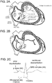
- Figure 2A shows a schematic of the heart cut-open to reveal the inside of the right atrium 37 and right ventricle 38 (cut surfaces shown in grey).
- the right atrium and right ventricle are separated by the tricuspid valve 34.
- FIG. 2A demonstrates the essential components of the electrical function of the heart.
- the electrical impulse originates in the sinoatrial node 35 (the pacemaker) located in the right atrium and propagates, as shown in figure 2B , through the atria to reach the atrioventricular node.
- the atrioventricular node is called the "AV node".
- the AV node is the sole electrical connection between the atria (upper chambers of the heart) and ventricles (lower chambers of the heart), and conducts the impulse to the ventricles.
- the AV node acts as a temporal filter, limiting the rate at which the ventricles can be electrically stimulated, which protects the ventricles against excessively fast atrial rhythms.
- the AV node allows co-ordination of atrial and ventricular contraction.
- Atrial side Slow pathway, fast pathway
- the AV node On the atrial side, the AV node has a diffuse structure into which the electrical impulse enters.
- This structure consists of limbs that display varying conduction speeds. These limbs are commonly known as the fast pathway 32 and slow pathway (33), as shown in figure 2A . However there may be more or less than two physiologically distinct limbs, and the limbs represent functional rather than anatomically defined inputs.
- Ventricular side His bundle, Purkinje fibre branches
- the conducting limbs of the AV node coalesce to form a more discrete structure, known as the compact AV node 31, which funnels the propagating impulse to a cable-like structure known as the "His bundle” 30 which directs depolarisation to the ventricles, via the Purkinje fibre branches 41.
- His bundle 30 and Purkinje fibres 41 support a high conduction velocity, enabling rapid propagation of the electrical impulse towards and throughout the ventricular tissue.
- Electrograms recorded inside the heart are typically of 1-10 milliVolts (mV) in amplitude.
- Cardiac tissue depolarisation also gives rise to electrical potential on the body surface, which is recorded on the surface electrocardiogram called ECG and shown in figure 2C .
- Atrial tissue depolarisation causes a small voltage signal known as the p wave 44, whereas ventricular tissue depolarisation leads to generation of a larger electrical potential on the body surface, known as the QRS complex 45, which is usually 1-5 mV in amplitude.
- the QRS complex is of narrow morphology, meaning typically ⁇ 120ms in width.
- the QRS complex becomes widened, specifically > 120ms.
- the interval between onset of the p wave and onset of the QRS complex is known as the PR interval 46, and indicates the time taken for the electrical impulse to traverse between atria and ventricle.
- the PR interval can be assessed in surrogate fashion by the interval between atrial and ventricular intracardiac electrogram recordings (described as the A-V interval), or by using the atrial intracardiac electrogram and the surface ECG QRS complex.
- an abnormal connection termed 'accessory pathway' 50 is present between the atria and ventricles.
- the electrical impulse is able to travel from atria to ventricles not only via the AV node, but also via the accessory pathway.
- the presence of an accessory pathway may alter the morphology of the normal QRS complex 45, making it wider and with a slurred upstroke.
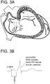
- Figure 3B depicts such a QRS complex, referred to as a 'pre-excited' QRS.
- the normal PR interval 46 may be shorted to become ⁇ 120ms as represented in figure 3B .
- Individuals with a pre-excited QRS are said to have the Wolff-Parkinson-White syndrome, and in rare cases are prone to sudden cardiac death, due to loss of the temporal filtering properties of AV node conduction.
- arrhythmia occurs when there is disturbance of the normal sequence of spread of electrical impulse. Often, arrhythmia is caused by 're-entry', where impulse propagation re-enters previously depolarised (activated) tissue in a circular fashion, causing repeditive and rapid activation of tissue, which leads to sudden elevation of heart rate. For re-entry to occur, a circuit of cardiac tissue is required, typically around an anatomical or functional obstacle, through which the impulse wave is unable to propagate.
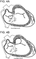
- This circuit can be formed by the two limbs of the AV node, in which case the arrhythmia is termed atrioventricular nodal re-entrant tachycardia called AVNRT and shown in figure 4A . Because these limbs have different functional (electrical) properties, they are apt to sustain re-entry in susceptible persons.
- the re-entrant circuit may be formed by the AV node and an accessory pathway, in which case the arrhythmia is termed atrioventricular reciprocating tachycardia called AVRT and shown in figure 4B .
- Ablation for AVNRT is typically performed over the slow pathway of the AV node 33 to disrupt or modify the slow pathway to an extent that re-entrant impulse propagation is no longer possible.
- Figure 5 depicts ablation over the slow pathway 33 using an ablation catheter 12, with an additional diagnostic catheter 13 placed in the position of the high right atrium.
- Ablation for AVRT is typically performed over the accessory pathway 50, which may lie anywhere along the valve planes that separate the atria and ventricles.
- the accessory pathway 50 may be close, or adjacent, to the AV node, lying on the inter-atrial septum, as demonstrated in FIG. 3A . In these cases it is described as being located in mid- or antero- septal location. Ablation of a mid- or antero- septal accessory pathway may be undertaken for the purposes of cure of AVRT, or for the prevention of sudden cardiac death in individuals with the Wolff-Parkinson-White (WPW) syndrome.
- WPW Wolff-Parkinson-White
- Catheter ablation is generally performed following a diagnostic electrophysiology study, in which the mechanism of arrhythmia is determined.
- diagnostic study generally requires a minimum of two catheters, one of which may be the ablation catheter 12.
- One catheter is placed in the right atrium or coronary sinus to record an atrial intra-cardiac electrogram A IEGM.
- Another catheter is placed alternately between the region of the His bundle to record a His electrogram, and the right ventricular apex to record a ventricular intra-cardiac electrogram V IEGM. Additional catheters may also be placed according to operator preference to allow the simultaneous recording of IEGMs in more locations.
- the heart rhythm is manipulated (stimulated) by pacing protocols in ways that define the arrhythmia mechanism.
- programmed stimulation is required from both the atria and the ventricles in order to define the mechanism of arrhythmia.
- AVNRT AVNRT
- AVRT AVRT
- a septal accessory pathway a minimum of two catheters is generally required, one being the ablation catheter, and the other being the catheter recording an atrial intra-cardiac electrogram.
- the atrial intra-cardiac electrogram is required primarily because atrial electrical activity is not always well seen on the body surface ECG, due to atrial activity being of smaller amplitude compared to ventricular activity. At times, it is also necessary to perform atrial pacing during ablation.
- Catheter ablation of arrhythmia is generally a well-tolerated procedure., however, carries a degree of risk. Specifically, ablation of either AVNRT, or a mid- or antero- septal accessory pathway, risks damage to the compact AV node or His bundle due to the proximity of the ablation catheter to these structures as shown in figure 5 .
- AV block describes a condition where conduction of electrical impulses between the atria and ventricles is limited or completely extinguished.
- Heart block leads to a loss of co-ordination between the atria and the ventricles, and can lead to a lowering of ventricular heart rate, loss of blood pressure, loss of consciousness, or even death.
- Ablation for mid- or antero- septal AP comprises ⁇ 5% of all ablation procedures, however, the risk of AV block is higher than for AVNRT, and is estimated at about 2-5%.
- Ablation of AVNRT or AVRT is generally performed during normal (sinus) heart rhythm, however may be performed during tachy-arrhythmia.
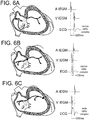
- heart rhythm may be expected to fluctuate between sinus rhythm as shown in figure 6A , junctional rhythm as shown in figure 6B , or ventricular ectopic rhythm as shown in figure 6C .
- each atrial depolarisation as seen on the atrial intracardiac electrogram A IEGM, should be followed within ⁇ 250ms by a ventricular depolarisation, as seen either on a ventricular intracardiac electrogram V IEGM, or, on the surface ECG as a QRS complex, as shown in figure 6A .
- Junctional rhythm is caused by heating to the slow pathway 33 and compact AV node 31 and/or His bundle 30, and describes a concentrically propagating wavefront emanating from the AV node or His bundle and causing near simultaneous atrial and ventricular activation, such that atrial depolarisation and ventricular depolarisation occur within ⁇ 130ms of each other.
- Ventricular ectopic rhythm describes activation commencing in the ventricular tissue, with retrograde AV nodal conduction to the atria, as illustrated in figure 6C , such that each atrial depolarisation should lag ventricular depolarisation by no more than ⁇ 250ms.
- Ventricular ectopic rhythm can occur spontaneously, or be induced by the presence of a catheter in the ventricle, in which case it is caused by the mechanical action of the catheter against the ventricular wall.
- activation of the ventricles is not via the His and Purkinje fibres, and accordingly the QRS complex of the ECG is widened and of different morphology to normal as shown in figure 6C .
- timing limits of 130ms and 250ms described here are a guide, and may differ based on exact location of intracardiac catheters or placement of ECG leads, and the heart rate and physiology of the individual patient. Nonetheless, absolute timings prove a reliable method of determining abnormal electrical impulse conduction in the AV node.
- AV block caused by ablation is often heralded by changes in the expected cardiac rhythms described above. There may be transient loss of atrio-ventricular association, such that each atrial depolarisation is not followed by a ventricular depolarisation, or vice versa, or the time limits for atrial or ventricular depolarisation outlined above are exceeded. In other cases, excessively rapid junctional rhythm (>130 beats per minute) may indicate impending AV block. In yet other cases, a prolongation of the normal PR interval 46 may indicate imminent AV block.
- AV block may also be heralded by sudden displacement of the ablation catheter tip away from the desired location of ablation, towards the compact AV node 31 and/or His bundle 30.
- Such displacement can be detected radiographically by continuous low-intensity x-ray (fluoroscopy) of the catheter, or, via the monitoring of catheter tip location with 3-dimensional mapping systems 19 which typically use impedence and/or magnetic tracking methods to localise the catheter tip.
- the risk of causing heart block varies according to the which of the above conditions is identified. For example, rapid junctional rhythm in isolation may portend less risk than PR interval lengthening. In another example, rapid junctional rhythm in isolation may portray less risk compared to the same rhythm combined with loss of atrio-ventricular association. Moreover, a sudden unexpected shift of catheter tip location in itself may herald less risk than a shift combined with change in cardiac rhythm. There is, therefore, a gradation of risk, and the level of risk accepted during ablation will depend on the operator and the patient-specific circumstances of ablation.
- Boveja et al. The US patent No. 7,578,816 B2 (Boveja et al. ) is directed toward control of ablation in similar cardiac rhythms.
- the Boveja application mainly discloses using automated monitoring of cardiac rhythm based exclusively on intracardiac signals, acquired from within both an atrial chamber and a ventricular chamber. This approach suffers several important limitations, which the present invention seeks to address.
- this solution (Boveja application) requires placement of a third catheter during ablation, namely a ventricular catheter.
- a third catheter during ablation, namely a ventricular catheter.
- the use of an additional catheter adds considerable cost to the procedure.
- ventricular ectopic rhythm As shown in figure 6C . This is related to the mechanical action of the catheter on the ventricular tissue. Although ventricular ectopic rhythm can be reduced by careful catheter placement, it cannot usually be completely eliminated.
- FIG. 8 Evidence of such increase in ventricular ectopic rhythm is shown in FIG. 8 , which documents the percentage of ventricular ectopic rhythm observed during 215 routine ablations performed in 20 patients, with a ventricular catheter placed by a clinician expert in the field of cardiac ablation, and during 196 ablations performed in 20 patients without a ventricular catheter placed.
- the former group only 36% of ablations were not complicated by ventricular ectopic rhythm, and the remaining 64% of ablations suffered from ventricular ectopic rhythm ranging from 0.1% to 20% of all heart beats.
- 95% of ablations were not complicated by ventricular ectopic rhythm, and only 5% of ablations suffered from ventricular ectopic rhythm, of ⁇ 2% of all heart beats.
- Ventricular ectopic rhythm during ablation is undesirable because it may limit the ability to discern the integrity of AV nodal conduction, and therefore continue ablation in a safe manner. This is because if a ventricular ectopic beat occurs in the period immediately following initiation of a sinus beat in the sinoatrial node 35, the state of AV nodal conduction is indeterminate, meaning that it cannot be determined if the electrical impulse was safely conducted by the AV node, or indeed, if AV block had occurred.
- the phenomenon of ventricular ectopic rhythm masking the integrity of AV nodal conduction is illustrated in FIG. 9A , and an example of signals acquired from a patient during ablation demonstrating this phenomenon is given in FIG. 9B .
- ventricular intracardiac recordings for discerning cardiac rhythm limits a device's ability to distinguish various cardiac rhythms. For example, such a device is unable to:
- Boveja application is limited to automated cut-out of ablation via placement of a control switch within the power supply line of the ablation generator, or between the ground patch and the ablation generator unit, or between the generator unit and the ablation catheter.
- One aspect of the invention concerns, a monitoring system for ablation of cardiac tissue in close proximity to the AV node of the heart, in order to improve the safety of ablation.
- the monitoring system of the invention comprises :
- the monitoring system comprises at least one calculator and a memory for measuring in real time a displacement of the ablation catheter tip in order to refine the Risk Index (Ri) when detecting a displacement of the ablation catheter exceeding a predefined limit.
- real time displacement of the ablation catheter away from the desired ablation location is determined from at least one of (i) catheter localisation based on object tracking in fluoroscopic low-dose x-ray images, or (ii) three-dimensional catheter tip position obtained from measurement of impedance and/or magnetic field at the catheter such as performed in an EP mapping system.
- the system of the invention is directed to improvement of the safety of ablation when applied close to the AV node.
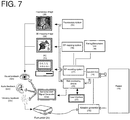
- a system is described in figure 7 that allows real-time or near real-time monitoring of cardiac rhythm and catheter tip location via a Risk Monitoring Device in order to assess rhythm conditions and catheter movements that may herald development of AV block.
- the system allows notification to the operator via sensorial alerts generated by a Sensorial Alert Signal Generator 25s, when cardiac rhythm or displacement conditions are identified that indicate risk of AV block. Such notification allows faster reaction times and increased consistency compared to human manual assessment of risk.
- An advantage of the invention compared to Prior Art is to utilise analysis of the body surface electrocardiogram ECG for determining ventricular depolarisation, in place of a ventricular intra-cardiac electrogram.
- the system employed incorporates both ECG QRS complex timing and morphology analysis.
- the system of the invention has the advantages of :
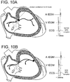
- the surface ECG can be used to reliably distinguish the rhythms of figures 10A and 10B based on analysis of QRS complex morphology.
- the QRS complex morphology In the case of junctional rhythm with impaired (slowed) AV nodal conduction, as shown in figure 10A , the QRS complex morphology is narrow, and ablation should be discontinued.
- the QRS complex In the case of ventricular ectopic rhythm with normal AV nodal conduction as shown in figure 10B , the QRS complex has a widened morphology, and it is safe to continue ablation.
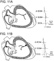
- the surface ECG can be used to reliably distinguish the rhythms of figures 11A and 11B based on analysis of QRS complex morphology.
- the QRS complex morphology is narrow, and it is safe to continue ablation.
- the QRS complex morphology is widened, and it may not be safe to continue.
- the risk level may be calculated as a weighted sum of the number of cardiac rhythm risk conditions together with catheter tip displacement measures.
- the Risk Index Ri is conveyed to the operator via a combination of sensorial alerts, with at least one alert emitted. These alerts include audio, visual, and vibratory signals which convey the magnitude of risk of continued ablation, one a graded scale from minimal to extreme risk. This allows the operator to make an instant informed decision whether to cease ablation. By keeping the human operator as the end decision-maker with respect to delivery or cut-out of therapy, the risk of machine-related harm is minimised, and ablation is able to be continued in situations of low risk if desired.
- the risk index Ri triggers an audible alert to the operator, projected by way of audio speaker and/or headphones, prompting the operator to discontinue ablation.
- the frequency of the audible alert varies according to the Risk Index Ri.
- the volume of the audible alert varies according to the Risk Index Ri.
- the audible alert is generated within a stand-alone Risk Monitoring Device 25.
- the audible alert is generated within existing equipment such as an ablation generator 16, EP recording system 17, or EP mapping system 19.
- the Risk Index Ri triggers a visual alert to the operator, prompting the operator to discontinue ablation.
- the visual alert is generated on an electronic monitor or screen associated with a stand-alone Risk Monitoring Device 25.
- the visual alert is generated on an electronic monitor or screen associated with existing equipment such as an ablation generator 16, EP recording system 17, or EP mapping system (19).
- At least one of colour, size, or pattern of the visual alert varies according to the Risk Index Ri.
- the Risk Index Ri triggers a vibratory alert to the operator, prompting the operator to discontinue ablation.
- the vibratory alert comprises vibration of the ablation catheter handle.
- the vibratory alert comprises vibration of the ablation foot pedal.
- At least one of the intensity or pattern of vibratory alert varies according to the Risk Index Ri.
- the system is configured to generate a unique combination of sensorial alerts depending on the Risk Index Ri which indicates the level of risk of heart block.
- the alert combination may comprise any combination of audio, visual, or vibratory alerts, using either synchronised or sequential timing.
- a first Risk Index RI1 may activate one visual alarm with an appropriated display
- a second Risk Index RI2 higher than the first Risk Index may activate a specific sound with an appropriated headphone.
- a third Risk Index RI3 higher than the second one RI2 may activate the visual alarm and the specific sound with a higher volume.
- the monitoring system may be achieved by the integration of a calculator or a set of calculators into one or more of an electrophysiology EP recording system 17, an electrophysiology EP mapping system 19, a Pacing/Stimulation Unit 18, a junction box 15, an ablation generator 16 or into a stand-alone Risk Monitoring Device 25.
- the monitoring system may be achieved by the integration of a memory or a set of memories into one or more of an electrophysiology EP recording system 17, an electrophysiology EP mapping system 19, a Pacing/Stimulation Unit 18, a junction box 15, an ablation generator 16 or into a stand-alone Risk Monitoring Device 25.
- the calculator comprises a signal timing function in order to derive timing of atrial and ventricular depolarisation, the atrial depolarisation being measured by the IEGM electrode, and the ventricular depolarisation being measured by the ECG electrodes.
- the signal timing function incorporates a voting function allowing the determination of signal timing when more than one IEGM or more than one ECG signal is available to characterise depolarisation timing.
- a voting function allowing the determination of signal timing when more than one IEGM or more than one ECG signal is available to characterise depolarisation timing.
- the monitoring system comprises only one catheter which comprises at least one electrode allowing the acquisition of an intracardiac electrogram, as the IEGM electrode.
- the signal timing function compares the delay between atrial and ventricular depolarisations to a minimum predefined threshold of time and/or a maximum predefined threshold of time.
- the signal timing function is configured for contributing to the Risk Index Ri when said measured delay exceeds at least one of the predefined thresholds.
- the calculator comprises a QRS complex signal morphology function in order to determine the nature of the ventricular depolarisation as being via the His bundle and Purkinje fibre branches , or, via a ventricular ectopic, or, via an accessory pathway.
- the signal morphology function compares an acquired QRS complex signal with one or more template QRS complexes stored in a memory, the comparison being processed using an auto-correlation function or a cross-correlation function.
- the signal morphology function is configured to compute the QRS complex width and/or to determinate deflection sequence of the complex QRS signal.
- the signal morphology function incorporates a voting function allowing the determination of signal morphology when more than one ECG signal is available to characterise depolarisation morphology.
- a voting function allowing the determination of signal morphology when more than one ECG signal is available to characterise depolarisation morphology.
- the calculator is configured to characterise the real time or near real time cardiac rhythm given return values of the signal timing function and/or a return value of the signal morphology function.
- One advantage is to accurately define cardiac rhythm and detect rhythms which indicate a risk of AV block, allowing the automatic cut-out of ablation power.
- the cardiac Risk Index Ri is a probability of AV block occurrence, said probability being characterised by at least one occurrence of :
- the memory allows storage of data acquired by the electrodes, storage of QRS complex templates for the purpose of morphology analysis, and storage of predefined parameters such as the cardiac rhythms and ablation catheter tip displacements deemed to indicate risk of AV block.
- the calculator comprises a mapping function allowing the real-time or near real-time automatic tracking of the location of the tip of the ablation catheter.
- the location of the catheter tip is determined in three-dimensions by data provided by a method for catheter tracking based on impedance or magnetic measurements such as those used in an EP mapping system 19.
- the location of the catheter tip is determined in two or three dimensions by analysis of catheter tip movement based on object tracking using low dose x-ray (fluoroscopy) images.
- the calculator is configured to account for the type of ablation procedure, being one of AVNRT, AVRT, or accessory pathway (50) ablation.
- the type of ablation procedure being one of AVNRT, AVRT, or accessory pathway (50) ablation.
- One advantage is to allow tolerance of different cardiac rhythms or the setting of different AV node conduction time limits depending on the type of ablation being performed.
- the calculator comprises a signal amplification function, a filtering function, an analog to digital conversion function, and computational analysis functions of signal timing and signal morphology.
- One advantage is elimination of noise from the IEGM and ECG signals, and conversion of signals to digital format thereby allowing digital processing by the signal timing and morphology functions.
- the monitoring system comprises a foot pedal 20 for manually switching off the power source 16 of the ablation catheter 12 via foot pedal release
- the monitoring system comprises a user interface allowing the selection of :
- One advantage is to account for a specific patient's physiology, such that tolerance to various cardiac rhythms and/or atrio-ventricular conduction delays can be incorporated to avoid false positive cut-outs of ablation energy. Yet a further advantage is to allow for operators of various experience level, ranging from novice operators for whom cut-out parameters will be stringently set, to experienced operators for whom some cut-out parameters may be relaxed.
- the monitoring system comprises a screen displaying pulse markers in real time, the pulse markers corresponding to a onset or a peak of each electrophysiology recording acquired by the IEGM electrode and the ECM electrodes.
- the monitoring system comprises a pacing unit that provides current pulses at programmed rates and patterns for stimulating the heart.
- the monitoring system comprises a junction box that provides a common interface gathering the connections of ECG electrodes and IEGM electrode and delivers the acquired signals to the calculator.
- Another object of the invention concerns a monitoring method achieving automatically the functions supported by the calculator of the system of the invention.
- the monitoring method increases safety of cardiac ablation when applied in close proximity to the AV node, by automated assessment of risk in response to cardiac rhythm related markers of risk for heart block, comprising the steps of:
- computational analysis of signal timing comprises methods of determining onset or peak of electrogram depolarisation deflection, and electrocardiogram QRS complex.
- computational analysis of signal morphology comprises methods of determining the extent of electrocardiogram QRS complex match to a template QRS complex signal, and methods of determining electrocardiogram QRS complex width and sequence of deflections.
- computational analysis can be written using development tools and graphical programming applications or languages such as LAB WINDOWS®/CVI, LABVIEW®, MICROSOFT VISUAL BASIC®, MICROSOFT VISUAL C++®, or functionally equivalent software
- the results of computational analysis of signal timing are displayed in real-time or near real-time, in the form of pulse markers, on an electrophysiology recording system monitor, to allow a visual check of said computational analysis integrity.
- the method may be incorporated into or combined with or embedded with an ablation generator.
- the method may be incorporated into or combined with or embedded with an electrophysiology recording system.
- the method may be incorporated into or combined with or embedded with an electrophysiology mapping system.
- ablation is performed for atrio-ventricular nodal re-entrant tachycardia (AVNRT), or for mid-septal or antero-septal accessory pathway ablation.
- APNRT atrio-ventricular nodal re-entrant tachycardia
- ablation is one of: radiofrequency RF ablation, cryoablation, high intensity focused ultrasound HIFU ablation, or microwave ablation.
- atrio-ventricular dissociation refers to an atrial depolarisation without a corresponding ventricular depolarisation within a given time limit.
- ventriculo-atrial dissociation refers to a ventricular depolarisation without a corresponding atrial depolarisation within a given time limit.
- a user interface is provided to the operator or ancillary staff in order to alter settings and parameters which trigger said automatic stopping of energy delivery, based on the type and location of ablation being performed, the nature of the patient's physiology, and operator personal preference.
- Catheters are placed inside of the heart 11 usually via the femoral veins. A minimum of two catheters is generally required to diagnose arrhythmia mechanism.
- One or more diagnostic catheters 13 are placed to allow both recording of intracardiac electrograms, and programmed stimulation of the heart. Diagnostic catheters are typically connected to junction box 15 which feeds signals to an electrophysiology (EP) recording system 17.
- EP electrophysiology
- ECG electrocardiogram
- An ablation catheter 12 is used to direct ablation energy to specific areas of the heart found to be critical to either arrhythmia triggering or maintenance.
- the ablation generator unit 16 which connects to the ablation catheter, provides the energy for ablation. It is one example of the power source of the ablation catheter 12. This may be in the form of radiofrequency (RF) current, cryo (freezing), high intensity focused ultrasound (HIFU), microwave energy, or other forms; RF being the most commonly employed presently.
- RF radiofrequency
- Examples of current commercially available RF generators include :
- the ablation generator can usually be controlled (that is to say, ablation energy commenced and terminated) by a switch on the unit, or, by a foot pedal 20.
- the EP recording system 17 is used to condition (amplify and filter) the intracardiac and ECG signals, convert these to digital form, and display these to the operator and technical staff on a PC monitor(s) 21, for the purposes of performing the procedure.
- Examples of current commercially available EP recording systems include :
- the EP mapping system 19 may also be used to condition and display intracardiac and ECG signals, but also performs the function of displaying three-dimensional catheter position relative to a reconstructed cardiac geometry, which augments standard x-ray based fluoroscopic methods of catheter navigation.
- Examples of current commercially available EP mapping systems include :
- the Pacing/Stimulation Unit 18 provides current pulses to stimulate the heart at programmed rates and patterns, to assist in the diagnosis of arrhythmia mechanism.
- Pacing/Stimulation Units examples include:
- FIG. 1 represents one configuration of connectivity of items that may be implemented according to the invention.
- the Pacing/Stimulation Unit may be integrated into an EP recording system, as in, for example, the commercially available ClarisTM EP recording system (St Jude Medical).
- the invention allows prediction of occurrences of AV block by analysing recorded signals and ablation catheter tip location.
- AV block may be heralded by changes seen in the cardiac signals displayed on the EP recording system monitor 21. Specifically, the occurrence of transient dissociation of atrial and ventricular depolarisation may indicate impending heart block, and can be detected by analysis of the intracardiac atrial electrogram IEGM together with the body surface ECG, wherein each atrial or ventricular signal is not associated with a counterpart ventricular or atrial signal within a defined time period as illustrated in figures 12A and 12B .
- fast junctional rhythm as illustrated in figure 12C
- consecutive atrial or ventricular depolarisations as illustrated in figure 12D
- PR interval prolongation as illustrated in figure 12D
- impending heart block may indicate impending heart block.
- the invention comprises a system for supplementing human visual feedback 22 with automated assessment of at least one of cardiac rhythm and catheter position, allowing automatic generation of a sensorial alert when conditions indicating risk of heart block occur.
- the system disclosed is able to react to risk conditions faster than the human reaction, and in a more consistent manner.
- cardiac rhythm analysis is performed with use of one or more atrial intracardiac electrogram signal IEGM, and the use of one or more body surface ECG signal.
- these signals are split from the Junction Box 15 shown in figure 7 into the Risk Monitoring Device 25, or alternatively are derived from connection between the Risk Monitoring Device 25 and the EP recording system 17 or EP mapping system 19.
- Other specific connectivities are possible, for example direct catheter connection to the Risk Monitoring Device 25 bypassing the Junction Box 15, and remain within the scope of the invention.
- the Risk Monitoring Device conditions the signals by amplification, filtering, and analog-to-digital conversion. Alternatively, partially or fully preconditioned signals may be obtained from the EP recording system 17 or EP mapping system 19 and input to the Risk Monitoring Device 25.
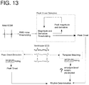
- the Risk Monitoring Device performs real-time or near real-time computational analysis of signals in order to derive timing of atrial and ventricular depolarisation, in the former based on peak or onset of atrial electrogram deflection, and in the latter based on peak or onset of ECG QRS complex deflection as shown in figure 13 .
- ECG QRS complex morphology is also performed to determine the nature of ventricular depolarisation, specifically, whether ventricular depolarisation arises from a junctional or ectopic beat, and whether ventricular depolarisation is exclusively via the AV node, or pre-excited from an accessory pathway.
- a voting algorithm may be employed to determine a majority decision as shown in figure 13 .
- timing analysis may be performed with a threshold of signal magnitude and/or derivative, with the threshold fixed to a percentage of the preceding n th number of signal peaks.
- an alternate method may employ signal phase analysis (for example utilising a Hilbert's transform) with signal timing defined by a zero crossing of phase.
- morphology analysis may be performed using auto-correlation based matching of the real-time QRS complex with a template QRS, the template QRS having been automatically stored from the same patient at procedure onset, prior to ablation.
- additional morphology analysis methods may employ cross-correlation of QRS signal with generic (derived from other individuals) template signals from normal and ectopic beats, as well as from other conditions causing change to QRS morphology such as impaired conduction in the Purkinje fibre branches 41 (so-called "bundle branch block").
- Yet further methods may employ determination of QRS complex width, and QRS signal positive/negative deflection sequence.
- the Risk Monitoring Device 25 outputs pulsed (square wave) signals to the EP recording system 17, via connection to the Junction Box 15 ( FIG. 7 ), to mark the timings of atrial and ventricular depolarisations, as determined by the Risk Monitoring Device. As shown in FIG. 14 , these pulses are thus able to be displayed on the PC 21 in real or near-real time, in order to provide a visual check that the Risk Monitoring Device is functioning correctly.
- DAQ data acquisition
- sbRIO-9639 National Instruments, NI
- Similar DAQ cards from the same or other manufacturers could be employed.
- Processing of atrial IEGM and ECG signals can performed in real-time on the microprocessor or the FPGA of the NI sbRIO-9639. Testing of the applicant's prototype has been performed using the aforementioned NI sbRIO-9639, with software written in LABVIEW®. Use of other programming languages or methods of data acquisition are considered within the scope of the invention.
- the preferred embodiment of the invention is for the Risk Monitoring Device 25 to generate a sensorial alert, to which the operator and assistance(s) can react to terminate ablation energy.
- a first threshold may be defined as a fist risk index
- a second threshold may defined as a second risk index which is higher than the first risk index
- a third threshold which is higher than the second risk index may be defined in order to automatically engage cut out of the catheter energy when the consequence of the ablation lead to a high risk of heart block.
- the invention allows defining different strategies for alerting an operator including stopping the ablation when the risk index is superior to a third threshold.
- a preferred embodiment of the invention includes sensorial alerts that combine at least one of a audio, visual, and vibratory alert.
- the volume and tone of the alert can be set to indicate the level of risk of continued ablation.
- a binary audio alert for example a "beep”
- the visual alert the colour, size, and pattern of the alert, displayed on, for example, an LCD screen, is used to indicate to the operator the degree of risk.
- the vibratory alert the intensity or amplitude, and pattern of vibration can be set in order to indicate to the operator the degree of risk.
- a preferred embodiment includes the incorporation of a vibratory alert into the handle of the ablation catheter, so that it can be felt directly through the operator's hand.
- the Risk Monitoring Device is able to give feed-back on the reaction time of the operator (releasing the foot pedal) to the sensorial alert.
- the Risk Monitoring Device is connected to a user interface 27, as represented in figure 7 , which allows operator-led adjustment of the parameters causing automated sensorial alert.
- FIG. 15 An example of a suitable user interface is shown in figure 15 .
- the heart rate causing cut-out, if any, for Fast Junctional Rhythm as shown in figure 12C can be selected using the "Junctional Rate Cut-off" knob as shown in figure 15 .
- A-V interval the maximum delay allowed between atrial and ventricular depolarisations
- the specific alert conditions set will depend on the type of ablation being performed, the particular patient's physiology, and individual operator preference. For example, a patient with pre-existing slow / diseased conduction of electrical impulse from atria to the ventricles, so-called first degree heart block, may need allowance of longer A-V intervals compared to a patient with normal baseline atrio-ventricular conduction. Similarly, an operator with many years of experience in ablation may chose less conservative settings on the device compared to an operator with less experience.
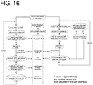
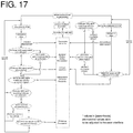
- the main differences between algorithms relates to the response to junctional rhythm and PR interval change.
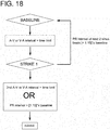
- An additional algorithm may also be employed that allows continued ablation without an alert despite the occurrence of a single dissociated beat, as for instance a single A without V, or a single V without A, corresponding to the cases illustrated in figures 12A and 12B , yet generates an alert in response to multiple dissociated beats.
- This algorithm is shown in figure 18 , and is intended as an "advanced" mode of ablation, to be used for ablation in patients with a high number of non-conducted ectopic beats, or for operators of sufficient skill that cut-out of ablation for a single non-conducted beat is deemed unnecessary.
- the algorithm shown in figure 18 is based around requirements of two "strikes" for the device to alarm :
- the first strike is able to be redeemed by the subsequent occurrence of two consecutive sinus beats of normal PR interval.
- the Risk Monitoring Device 25 may be a stand-alone piece of equipment. In other embodiments, it could be variously incorporated into an ablation generator 16, as shown in figure 19A , an EP recording system 17, as shown in figure 19B , or an EP mapping system 19, (not shown).
- the Sensorial Alert Signal Generator 25s may also be incorporated into the circuitry and/or housing of the same item of equipment.
- the present invention can be equally used with any form of ablation energy, including but not limited to radiofrequency (RF) ablation, cryo-ablation, high intensity focused ultrasound (HIFU) ablation, and microwave ablation.
- RF radiofrequency
- HIFU high intensity focused ultrasound
- a prototype has been developed using the preferred strategy outlined above, and tested on signals acquired from 19 patients (208 ablation episodes) during the course of AVNRT ablation via slow pathway ablation or modification.
- EGM and ECG peak detection Activity in the atrium and ventricles was assessed using EGM and ECG peak detection, by way of voltage magnitude and 1st derivative adaptive thresholding as described above, incorporating a threshold decay function to allow resumption of detection after lead or catheter disconnection.
- Subsequent rhythm determination was by rule-based analysis, incorporating QRS complex morphology matching to distinguish junctional from ventricular ectopic beats.
- Post detection blanking intervals of 180ms and 200ms were applied to the atrial and ventricular signals respectively, to prevent double counting of activations. No blanking period was applied to the atrial signal following ventricular activation, to ensure that junctional rhythm could be adequately tracked.
- Cardiac rhythm was arbitrarily classified as 'sinus' where there was sequential atrial and ventricular depolarisation separated by ⁇ 90 ms, 'ventricular' where there was sequential ventricular and atrial depolarisation separated by ⁇ 90 ms, and 'junctional' where atrial and ventricular depolarisations were within 90ms of each other.
- the algorithm shown in figure 16 was programmed in the graphical language LabViewTM 12.0 (National Instruments; ni.com), and implemented on a National Instruments Single-board RIO microprocessor.
- the nominal settings that would trigger a sensorial alert were :
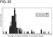
- the invention prototype performance is summarised in figure 21 .
- the device assigned accurate times to atrial depolarisations in all but 10 / 15,317 cases, and to ventricular depolarisations in all but 2 / 15,437 cases.
- the inaccurate timings occurred in 3 patients.
- 8 were due to under-detection of small amplitude EGM signals during periods of sudden diminution of signal amplitude (example given in figure 22A , with an example of successful detection in similar circumstances given in figure 22B ).
- inaccurate assignment was due to sudden large amplitude fluctuation in EGM baseline, caused by patient movement.
- There were no cases of over-detection of ventricular far-field signal on the atrial EGM (example in figure 22C ).
- the two cases of inaccurate timing assignment in ECG peak were due to the well described phenomenon of T wave over-sensing.
- response speed of the device was compared to the speed of manual RF foot-pedal release.
- the device performed a median of 1,238 ms faster (range 14 to 132,919) than the human response. In no cases did the device lag human response.
Landscapes
- Health & Medical Sciences (AREA)
- Life Sciences & Earth Sciences (AREA)
- Surgery (AREA)
- Engineering & Computer Science (AREA)
- Plasma & Fusion (AREA)
- Medical Informatics (AREA)
- Otolaryngology (AREA)
- Physics & Mathematics (AREA)
- Cardiology (AREA)
- Biomedical Technology (AREA)
- Heart & Thoracic Surgery (AREA)
- Nuclear Medicine, Radiotherapy & Molecular Imaging (AREA)
- Molecular Biology (AREA)
- Animal Behavior & Ethology (AREA)
- General Health & Medical Sciences (AREA)
- Public Health (AREA)
- Veterinary Medicine (AREA)
- Measurement And Recording Of Electrical Phenomena And Electrical Characteristics Of The Living Body (AREA)
- Surgical Instruments (AREA)
Priority Applications (1)
| Application Number | Priority Date | Filing Date | Title |
|---|---|---|---|
| EP16306464.5A EP3318210A1 (de) | 2016-11-08 | 2016-11-08 | Überwachungssystem für ablation von herzgewebe in nächster nähe zu dem av-knoten des herzens und zur erzeugung eines sensorischen alarms |
Applications Claiming Priority (1)
| Application Number | Priority Date | Filing Date | Title |
|---|---|---|---|
| EP16306464.5A EP3318210A1 (de) | 2016-11-08 | 2016-11-08 | Überwachungssystem für ablation von herzgewebe in nächster nähe zu dem av-knoten des herzens und zur erzeugung eines sensorischen alarms |
Publications (1)
| Publication Number | Publication Date |
|---|---|
| EP3318210A1 true EP3318210A1 (de) | 2018-05-09 |
Family
ID=57348610
Family Applications (1)
| Application Number | Title | Priority Date | Filing Date |
|---|---|---|---|
| EP16306464.5A Withdrawn EP3318210A1 (de) | 2016-11-08 | 2016-11-08 | Überwachungssystem für ablation von herzgewebe in nächster nähe zu dem av-knoten des herzens und zur erzeugung eines sensorischen alarms |
Country Status (1)
| Country | Link |
|---|---|
| EP (1) | EP3318210A1 (de) |
Cited By (5)
| Publication number | Priority date | Publication date | Assignee | Title |
|---|---|---|---|---|
| CN112890824A (zh) * | 2019-11-15 | 2021-06-04 | 伯恩森斯韦伯斯特(以色列)有限责任公司 | 用于在心内心电图中查找异常激动的方法 |
| WO2022118299A1 (en) * | 2020-12-06 | 2022-06-09 | Libra Science Ltd. | Intraoperative alarm monitor |
| WO2022127691A1 (zh) * | 2020-12-17 | 2022-06-23 | 杭州启明医疗器械股份有限公司 | 射频消融装置 |
| WO2022134713A1 (zh) * | 2020-12-23 | 2022-06-30 | 上海微创电生理医疗科技股份有限公司 | 脉冲消融设备、系统、控制方法及可读存储介质 |
| CN115177358A (zh) * | 2022-07-12 | 2022-10-14 | 上海宏桐实业有限公司 | 一种基于腔内信号的心腔内标测电极导管的定位方法及系统 |
Citations (4)
| Publication number | Priority date | Publication date | Assignee | Title |
|---|---|---|---|---|
| US7578816B2 (en) | 2005-04-22 | 2009-08-25 | Abl Technologies, Llc | Method and system of increasing safety of cardiac ablation procedures |
| WO2012151301A1 (en) * | 2011-05-02 | 2012-11-08 | Topera, Inc. | System and method for targeting heart rhythm disorders using shaped ablation |
| EP2901953A1 (de) * | 2014-01-29 | 2015-08-05 | Biosense Webster (Israel), Ltd. | Doppelt bipolare Konfiguration für Vorhofflimmernannotation |
| US20150265341A1 (en) * | 2014-03-18 | 2015-09-24 | Boston Scientific Scimed, Inc. | Electrophysiology system |
-
2016
- 2016-11-08 EP EP16306464.5A patent/EP3318210A1/de not_active Withdrawn
Patent Citations (4)
| Publication number | Priority date | Publication date | Assignee | Title |
|---|---|---|---|---|
| US7578816B2 (en) | 2005-04-22 | 2009-08-25 | Abl Technologies, Llc | Method and system of increasing safety of cardiac ablation procedures |
| WO2012151301A1 (en) * | 2011-05-02 | 2012-11-08 | Topera, Inc. | System and method for targeting heart rhythm disorders using shaped ablation |
| EP2901953A1 (de) * | 2014-01-29 | 2015-08-05 | Biosense Webster (Israel), Ltd. | Doppelt bipolare Konfiguration für Vorhofflimmernannotation |
| US20150265341A1 (en) * | 2014-03-18 | 2015-09-24 | Boston Scientific Scimed, Inc. | Electrophysiology system |
Cited By (5)
| Publication number | Priority date | Publication date | Assignee | Title |
|---|---|---|---|---|
| CN112890824A (zh) * | 2019-11-15 | 2021-06-04 | 伯恩森斯韦伯斯特(以色列)有限责任公司 | 用于在心内心电图中查找异常激动的方法 |
| WO2022118299A1 (en) * | 2020-12-06 | 2022-06-09 | Libra Science Ltd. | Intraoperative alarm monitor |
| WO2022127691A1 (zh) * | 2020-12-17 | 2022-06-23 | 杭州启明医疗器械股份有限公司 | 射频消融装置 |
| WO2022134713A1 (zh) * | 2020-12-23 | 2022-06-30 | 上海微创电生理医疗科技股份有限公司 | 脉冲消融设备、系统、控制方法及可读存储介质 |
| CN115177358A (zh) * | 2022-07-12 | 2022-10-14 | 上海宏桐实业有限公司 | 一种基于腔内信号的心腔内标测电极导管的定位方法及系统 |
Similar Documents
| Publication | Publication Date | Title |
|---|---|---|
| RU2529383C2 (ru) | Устройство и способ для автоматического определения местоположений источников нарушений биологического ритма | |
| US11633121B2 (en) | Ablation check pulse routine and integration for electroporation | |
| US9724018B2 (en) | Method for monitoring phrenic nerve function | |
| US6370412B1 (en) | Method and apparatus for guiding ablative therapy of abnormal biological electrical excitation | |
| EP3482679A1 (de) | System und verfahren zur bereitstellung von auditiver führung in medizinischen systemen | |
| US10874450B2 (en) | Highlighting region for re-ablation | |
| EP3318210A1 (de) | Überwachungssystem für ablation von herzgewebe in nächster nähe zu dem av-knoten des herzens und zur erzeugung eines sensorischen alarms | |
| US12426944B2 (en) | Automatically performing irreversible electroporation ablation during heart refractory period | |
| KR20130057998A (ko) | 생물학적 리듬 장애의 검출, 진단 및 처치를 위한 방법, 시스템 및 장치 | |
| EP3888550B1 (de) | Erkennung und abbildung des zwerchfellnervs durch stimulation | |
| CN115349944A (zh) | 脉冲消融系统 | |
| CN104414748A (zh) | 用于医学成像系统的图形用户界面 | |
| JP2016120280A (ja) | 心室遠距離場の低減 | |
| EP3090683A1 (de) | System zur automatischen rhythmusbasierten herzablationssteuerung in der nähe des atrioventrikularknotens | |
| US20180303345A1 (en) | System and Method for Imaging Episodic Cardiac Conditions | |
| JP2021146205A (ja) | ペーシングによって誘発された電気的活性化の評価 | |
| JP2024540634A (ja) | 心臓アブレーション病変の急性評価 | |
| JP2017532090A (ja) | 集束超音波心臓刺激システム、携帯デバイスおよび心臓刺激、ならびに関連方法 | |
| US20230226361A1 (en) | Cardiac mapping to evaluate impact of interventions | |
| CN117042839A (zh) | 用于植入式脉冲发生器的引线定位 | |
| WO2023135475A1 (en) | Cardiac mapping to evaluate impact of interventions | |
| US10588566B2 (en) | Ablation condition determination methods and systems | |
| WO2025145101A1 (en) | Visualization devices and techniques for implanting medical devices | |
| IL293942A (en) | Improving mapping resolution of electrophysiological (ep) wave propagating on the surface of patient heart | |
| TUYISENGE | „Prediction of cardiac electrophysiology signal characteristics from image features “ |
Legal Events
| Date | Code | Title | Description |
|---|---|---|---|
| PUAI | Public reference made under article 153(3) epc to a published international application that has entered the european phase |
Free format text: ORIGINAL CODE: 0009012 |
|
| AK | Designated contracting states |
Kind code of ref document: A1 Designated state(s): AL AT BE BG CH CY CZ DE DK EE ES FI FR GB GR HR HU IE IS IT LI LT LU LV MC MK MT NL NO PL PT RO RS SE SI SK SM TR |
|
| AX | Request for extension of the european patent |
Extension state: BA ME |
|
| STAA | Information on the status of an ep patent application or granted ep patent |
Free format text: STATUS: THE APPLICATION IS DEEMED TO BE WITHDRAWN |
|
| 18D | Application deemed to be withdrawn |
Effective date: 20181110 |