EP3318312A1 - Système de panier support - Google Patents
Système de panier support Download PDFInfo
- Publication number
- EP3318312A1 EP3318312A1 EP16196906.8A EP16196906A EP3318312A1 EP 3318312 A1 EP3318312 A1 EP 3318312A1 EP 16196906 A EP16196906 A EP 16196906A EP 3318312 A1 EP3318312 A1 EP 3318312A1
- Authority
- EP
- European Patent Office
- Prior art keywords
- ring
- longitudinal bars
- support basket
- support
- filter
- Prior art date
- Legal status (The legal status is an assumption and is not a legal conclusion. Google has not performed a legal analysis and makes no representation as to the accuracy of the status listed.)
- Withdrawn
Links
Images
Classifications
-
- B—PERFORMING OPERATIONS; TRANSPORTING
- B01—PHYSICAL OR CHEMICAL PROCESSES OR APPARATUS IN GENERAL
- B01D—SEPARATION
- B01D46/00—Filters or filtering processes specially modified for separating dispersed particles from gases or vapours
- B01D46/02—Particle separators, e.g. dust precipitators, having hollow filters made of flexible material
- B01D46/06—Particle separators, e.g. dust precipitators, having hollow filters made of flexible material with means keeping the working surfaces flat
-
- B—PERFORMING OPERATIONS; TRANSPORTING
- B01—PHYSICAL OR CHEMICAL PROCESSES OR APPARATUS IN GENERAL
- B01D—SEPARATION
- B01D2275/00—Filter media structures for filters specially adapted for separating dispersed particles from gases or vapours
- B01D2275/20—Shape of filtering material
- B01D2275/208—Oval shape
Definitions
- the invention relates to a support cage assembly comprising at least one support cage, which has a plurality of longitudinal bars and a plurality of identically formed, superimposed annular elements which are spaced apart in the longitudinal direction of the longitudinal bars, wherein the longitudinal bars along the circumference of the ring elements are positioned and secured thereto.
- the invention relates to a filter tube assembly comprising such a support cage assembly and at least one filter tube which is mounted on the support basket of the support cage assembly.
- Such filter tube arrangements are known from the prior art and in particular the DE 10 2005 041 521 B4 are known and used in particular for cleaning the flue gases of fossil fuels. For example, they are used in power plants, in waste incineration plants and technical installations.
- Such filter bag assemblies include filter bags which may be sewn from various materials such as polyester, polyacrylonitrile, aramid, polyphenylene sulfide (PPS), polyimide, polytetrafluoroethylene (PTFE), glass.
- stabilizing baskets for stabilization. These usually consist of a plurality of longitudinal bars, which are arranged in a circle and by a plurality of longitudinally spaced from each other in the longitudinal direction of the longitudinal bars arranged ring elements to which they are welded together are connected.
- such filter bag assemblies may include a perforated plate to divide the filter bag assembly into a clean gas side and a raw gas side. The filter hoses are arranged in openings of the perforated plate and sealed so that no dust-laden gas from the raw gas side can pass unfiltered into the clean gas side.
- the invention is based on the idea to optimize the ratio between the filter surface and the volume of the filter system by the filter bags are clamped elliptical.
- An elliptical filter tube has a larger outer surface compared to a circular filter tube with the same inner volume.
- the larger filter area available for an elliptical filter bag allows a higher filter performance.
- the outer sides of the ring elements can have an ellipse with a large half-axis of 7 to 11 cm, preferably 9 cm, and with a small semi-axis from 4 to 6 cm, preferably 5 cm, limit.
- a favorable ratio between the filter surface of the wound on the support basket filter bag and the inner volume of the filter tube is achieved.
- the longitudinal bars along the circumference of the ring elements are evenly distributed. This increases the stability of the support basket.
- the longitudinal bars may be attached to the outside of the ring elements. This makes the production of the support basket easy.
- the longitudinal bars of the support cage are retracted at their lower end regions and fastened to a smaller ring element which has the same geometric shape as the ring elements, wherein the smaller ring element has a smaller area, preferably one of 1% to 10%, particularly preferably spans a 2% to 4% smaller area than the ring elements.
- the lower end portions of the longitudinal bars may be secured to the inside of the smaller ring member.
- the cross section of the support basket is narrowed in the lower end region of the longitudinal bars.
- a bottom which is placed on the support basket from the underside and surrounds the lower ends of the longitudinal bars and possibly additionally the smaller ring member.
- the bottom element can be attached to the longitudinal bars and / or the smaller ring element, in particular welded. The retracted formation of the support basket at its lower end region ensures that the bottom element does not protrude beyond the outer large circumference of the support basket to the outside and thus a compact arrangement is obtained.
- the coupling ring may be provided with a bead, which extends in particular in the region of the transverse to the longitudinal bars center plane of the coupling ring.
- the lower end portions of the longitudinal bars are fixed to the inside of the smaller ring member.
- the support basket may have a different number of longitudinal bars depending on the geometric size. Conveniently, 10 to 20 longitudinal bars, in particular 12 or 18 longitudinal bars, are provided. It is also possible, in order to increase the stability on the inflow side and / or the outflow side of the support basket, to provide two longitudinal bars immediately adjacent to form a double-strut attachment.
- the support cage in the axially upper end region of the longitudinal bars is assigned a Venturi nozzle which has a tube piece which carries a head plate on its upper end.
- a Venturi nozzle which has a tube piece which carries a head plate on its upper end.
- the passage area of the pipe section is smaller than a passage area spanned by the ring elements.
- the passage area of the pipe section can be smaller by 10 to 40%, in particular by 20 to 30%, than the passage area spanned by the ring elements.
- the Venturi nozzle may be attached directly to the upper end of the support basket.
- the upper ends of the longitudinal bars are connected to the head plate, for example, welded.
- the head plate preferably has a plurality of passage openings around the elliptical passage opening, wherein a plurality of longitudinal bars each pass through a corresponding passage opening of the head plate and the ends of the longitudinal bars emerging from the passage opening are bent for attachment. In this way, a simple and stable attachment of the Venturi nozzle is made possible on the support basket.
- the filter tube comprises at its upper end portion a snap ring, which is in the form of an open ring and in particular is sewn into the filter tube. This allows the tool-free attachment of the filter tube in an opening of the perforated plate. In addition, a sealing of the filter tube is achieved in the perforated plate.
- the snap ring spring steel or consists of it.
- Such snap rings have a high resistance and long life.
- two retaining rings can be arranged on the outer surface of the snap ring, which sewn into the filter tube to form retaining beads are and enclose the filter tube along its entire circumference, wherein between the Garwülsten a receptacle for an adjacent to an opening of a perforated plate edge region of the perforated plate is defined. As a result, the upper end of the filter tube is held in the opening of the perforated plate.
- a single retaining ring which is arranged on the outer surface of the snap ring and sewn into the filter tube to form a retaining bead, may also be sufficient.
- At least one retaining ring preferably has a semicircular cross-section, the straight side of which faces the snap ring. Likewise, at least one retaining ring may have a circular cross-section.
- the retaining rings comprise or consist of an elastomer. This material is particularly well suited due to its elastic deformability.
- the filter tube assembly may include the orifice plate that divides the filter tube assembly in its longitudinal direction into an upper clean gas side and a lower raw gas side.
- the filter tube is arranged in an opening of the perforated plate. In this way it is possible to hold several filter bags by means of a perforated plate.
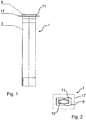
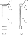
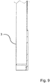
- FIGS. 1 to 9 show a filter bag assembly 1 according to a first embodiment of the present invention.
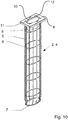
- This comprises a support basket assembly 2, which in the FIGS. 10 to 14 is shown, and a filter tube. 3
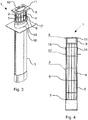
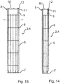
- the support basket assembly 2 comprises a support basket 4 with twelve longitudinal bars 5 and five ring elements 6.
- the ring elements 6 are of similar construction and arranged one above the other in the longitudinal direction of the longitudinal bars 5 at a distance from one another.
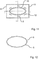
- the outer sides of the ring elements 6 define an elliptical surface without straight sections with a large half-axis of 9 cm and a small half-axis of 5 cm.
- the longitudinal bars 5 are uniformly distributed along the circumference of the ring elements 6 and secured to the outside thereof.
- the lower end portions of the longitudinal rods 5 are retracted and fixed to the inside of a smaller ring member 7, which has the same geometric shape as has the ring elements 6 and spans a 4% smaller area compared to these.
- the cross section of the support basket 4 is narrowed in the lower region of the longitudinal bars 5.
- the bottom element can be attached to the longitudinal bars 5 and / or the smaller ring element 7, in particular welded.
- the retracted formation of the support basket at its lower end region ensures that the bottom element does not protrude outwardly beyond the outer, large circumference of the support basket.
- the support basket 4 is assigned a venturi 8.
- This has an elliptical pipe section 9, which carries a head plate 11 at its upper end.
- the pipe section 9 and the head plate 11 define an elliptical passage opening 10, which is 20% smaller than the spanned by the ring elements 6 passage area.
- the Venturi nozzle 8 is attached to the upper end of the support basket 4 by means of a plug connection.
- the head plate 11 distributed around the elliptical passage opening 10 around six passage openings 12, which are penetrated in each case by an associated longitudinal bar 5, wherein their outgoing from the passage opening 12 ends are bent to the head plate 11.
- the longitudinal bars 5 can be welded to the head plate 11.
- the filter tube 3 is mounted on the support basket 4 of the support cage assembly 2 and extends over its entire length, so that the filter tube 3 protrudes beyond the lower end portion of the support basket 4.
- the filter hose 3 comprises a snap ring 13 made of metal, via which the filter hose 3 is fixed in a clamping manner to the support basket 4.
- the snap ring 13 is in the form of an open, outwardly tensionable ring and sewn into the filter bag 3.
- the filter tube 3 is formed closed at its lower end.
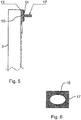
- two retaining rings 14 are arranged on the outside of the sewn into the filter hose 3 snap ring 13 made of elastomer, which are sewn to form retaining beads 14 in the filter bag 3 and enclose the filter bag 3 along its entire circumference.
- a receptacle 15 for a bordering to an opening 16 of a perforated plate 17 edge region of the perforated plate 17 is defined between the retaining beads 14.
- the retaining rings 14 have a semicircular cross section, whose straight side faces the snap ring 13.
- the filter tube assembly 1 comprises the perforated plate 17, which divides the filter tube assembly 1 in its longitudinal direction functionally into an upper clean gas side and a lower Rohgasseite.
- the filter tube 3 is disposed in the opening 16 of the perforated plate 17.
Landscapes
- Chemical & Material Sciences (AREA)
- Chemical Kinetics & Catalysis (AREA)
- Filtering Of Dispersed Particles In Gases (AREA)
Priority Applications (1)
| Application Number | Priority Date | Filing Date | Title |
|---|---|---|---|
| EP16196906.8A EP3318312A1 (fr) | 2016-11-02 | 2016-11-02 | Système de panier support |
Applications Claiming Priority (1)
| Application Number | Priority Date | Filing Date | Title |
|---|---|---|---|
| EP16196906.8A EP3318312A1 (fr) | 2016-11-02 | 2016-11-02 | Système de panier support |
Publications (1)
| Publication Number | Publication Date |
|---|---|
| EP3318312A1 true EP3318312A1 (fr) | 2018-05-09 |
Family
ID=57223571
Family Applications (1)
| Application Number | Title | Priority Date | Filing Date |
|---|---|---|---|
| EP16196906.8A Withdrawn EP3318312A1 (fr) | 2016-11-02 | 2016-11-02 | Système de panier support |
Country Status (1)
| Country | Link |
|---|---|
| EP (1) | EP3318312A1 (fr) |
Cited By (2)
| Publication number | Priority date | Publication date | Assignee | Title |
|---|---|---|---|---|
| CN112402778A (zh) * | 2020-11-24 | 2021-02-26 | 李争艳 | 一种肾内科应激按摩渗析构件 |
| CN117323751A (zh) * | 2023-09-27 | 2024-01-02 | 广东阁立恩科技有限公司 | 一种除尘布袋骨架 |
Citations (8)
| Publication number | Priority date | Publication date | Assignee | Title |
|---|---|---|---|---|
| DE3733255A1 (de) * | 1986-10-09 | 1988-04-21 | Tsukasa Ind | Schlauchfilter-staubsammler |
| DE19705967A1 (de) * | 1997-02-17 | 1998-08-20 | Quaschner Karl | Ellipsenschlauch mit Stützkorb |
| US20060107632A1 (en) * | 2004-11-24 | 2006-05-25 | Berkhoel James L | Filter frame for bag house filter, and method |
| DE102005041521B4 (de) | 2005-08-31 | 2008-04-03 | Voss & Eiffert Gmbh | Filterstützkorb |
| EP2162291A2 (fr) | 2007-06-29 | 2010-03-17 | manroland AG | Procédé d'impression d'une matière à imprimer |
| EP2163291A1 (fr) * | 2008-09-03 | 2010-03-17 | Voss & Eiffert GmbH | Panier d'appui de filtre |
| WO2012135881A1 (fr) * | 2011-04-04 | 2012-10-11 | Scheuch Gmbh | Filtre à manches pour l'épuration de gaz chargés de poussières et buse d'injecteur pour un tel filtre à manches |
| WO2013171860A1 (fr) * | 2012-05-16 | 2013-11-21 | 株式会社相模商会 | Dispositif de retenue |
-
2016
- 2016-11-02 EP EP16196906.8A patent/EP3318312A1/fr not_active Withdrawn
Patent Citations (8)
| Publication number | Priority date | Publication date | Assignee | Title |
|---|---|---|---|---|
| DE3733255A1 (de) * | 1986-10-09 | 1988-04-21 | Tsukasa Ind | Schlauchfilter-staubsammler |
| DE19705967A1 (de) * | 1997-02-17 | 1998-08-20 | Quaschner Karl | Ellipsenschlauch mit Stützkorb |
| US20060107632A1 (en) * | 2004-11-24 | 2006-05-25 | Berkhoel James L | Filter frame for bag house filter, and method |
| DE102005041521B4 (de) | 2005-08-31 | 2008-04-03 | Voss & Eiffert Gmbh | Filterstützkorb |
| EP2162291A2 (fr) | 2007-06-29 | 2010-03-17 | manroland AG | Procédé d'impression d'une matière à imprimer |
| EP2163291A1 (fr) * | 2008-09-03 | 2010-03-17 | Voss & Eiffert GmbH | Panier d'appui de filtre |
| WO2012135881A1 (fr) * | 2011-04-04 | 2012-10-11 | Scheuch Gmbh | Filtre à manches pour l'épuration de gaz chargés de poussières et buse d'injecteur pour un tel filtre à manches |
| WO2013171860A1 (fr) * | 2012-05-16 | 2013-11-21 | 株式会社相模商会 | Dispositif de retenue |
Cited By (2)
| Publication number | Priority date | Publication date | Assignee | Title |
|---|---|---|---|---|
| CN112402778A (zh) * | 2020-11-24 | 2021-02-26 | 李争艳 | 一种肾内科应激按摩渗析构件 |
| CN117323751A (zh) * | 2023-09-27 | 2024-01-02 | 广东阁立恩科技有限公司 | 一种除尘布袋骨架 |
Similar Documents
| Publication | Publication Date | Title |
|---|---|---|
| DE3534113A1 (de) | Perlator fuer wasserhahnmundstuecke | |
| DE102009009420A1 (de) | Wasserabscheider insbesondere für Kraftstoffzuführsysteme von Brennkraftmaschinen in Kraftfahrzeugen | |
| DE202007007120U1 (de) | Kraftstoffzuführeinrichtung, insbesondere für eine Brennkraftmaschine | |
| EP3145619A1 (fr) | Composant de cartouche filtrante comportant un élément filtrant plié | |
| EP3795233A1 (fr) | Élément de filtre à air | |
| EP0388849A2 (fr) | Filtre à arêtes pour liquides | |
| CH650572A5 (de) | Dichtungseinheit. | |
| EP3624920B1 (fr) | Filtre à vapeur | |
| EP2394030A2 (fr) | Filtre à vapeur et procédé de réalisation d'un filtre à vapeur | |
| DE102018008459A1 (de) | Vorrichtung für den Stoffaustausch zwischen Blut- und wenigstens einem Gas/Gasgemisch | |
| DE102009029679A1 (de) | Zylindrisches Dampfsieb | |
| DE102013004284B4 (de) | Filtereinrichtung und Filterelement für eine Filtereinrichtung | |
| EP1779915B2 (fr) | Panier de support pour tuyaux flexibles de filtre | |
| EP2165749B2 (fr) | Filtre pour milieux liquides et gazeux | |
| EP3743190B1 (fr) | Élément filtrant, en particulier pour la filtration de gaz | |
| DE202016008924U1 (de) | Stützkorbanordnung | |
| DE2439648C2 (de) | Mehrzyklonentstauber | |
| EP2094391A1 (fr) | Panier porteur d'une centrifugeuse à filtre | |
| DE2437451A1 (de) | Katalytischer konverter | |
| DE8124632U1 (de) | Filter fuer fluessigkeiten, insbesondere fuer kraftstoff | |
| DE102015103759A1 (de) | Niederschlagsrohrbündel für einen Nasselektrofilter sowie Nasselektrofilter | |
| DE102022124672B3 (de) | Funkenabscheider und Funkenabscheider-System | |
| EP3984616B1 (fr) | Dispositif de filtre et dispositif de séparation | |
| DE10219693A1 (de) | Düse für insbesondere eine Druckstoßreinigung von ringförmigen Gasfiltern | |
| DE102010000421B4 (de) | Rohrbündel-Wärmetauscher |
Legal Events
| Date | Code | Title | Description |
|---|---|---|---|
| PUAI | Public reference made under article 153(3) epc to a published international application that has entered the european phase |
Free format text: ORIGINAL CODE: 0009012 |
|
| STAA | Information on the status of an ep patent application or granted ep patent |
Free format text: STATUS: THE APPLICATION HAS BEEN PUBLISHED |
|
| AK | Designated contracting states |
Kind code of ref document: A1 Designated state(s): AL AT BE BG CH CY CZ DE DK EE ES FI FR GB GR HR HU IE IS IT LI LT LU LV MC MK MT NL NO PL PT RO RS SE SI SK SM TR |
|
| AX | Request for extension of the european patent |
Extension state: BA ME |
|
| STAA | Information on the status of an ep patent application or granted ep patent |
Free format text: STATUS: REQUEST FOR EXAMINATION WAS MADE |
|
| 17P | Request for examination filed |
Effective date: 20181105 |
|
| RBV | Designated contracting states (corrected) |
Designated state(s): AL AT BE BG CH CY CZ DE DK EE ES FI FR GB GR HR HU IE IS IT LI LT LU LV MC MK MT NL NO PL PT RO RS SE SI SK SM TR |
|
| STAA | Information on the status of an ep patent application or granted ep patent |
Free format text: STATUS: EXAMINATION IS IN PROGRESS |
|
| 17Q | First examination report despatched |
Effective date: 20191211 |
|
| STAA | Information on the status of an ep patent application or granted ep patent |
Free format text: STATUS: THE APPLICATION IS DEEMED TO BE WITHDRAWN |
|
| 18D | Application deemed to be withdrawn |
Effective date: 20200925 |