EP3318365B1 - Ratschenschlüssel - Google Patents
Ratschenschlüssel Download PDFInfo
- Publication number
- EP3318365B1 EP3318365B1 EP17167618.2A EP17167618A EP3318365B1 EP 3318365 B1 EP3318365 B1 EP 3318365B1 EP 17167618 A EP17167618 A EP 17167618A EP 3318365 B1 EP3318365 B1 EP 3318365B1
- Authority
- EP
- European Patent Office
- Prior art keywords
- ratchet
- pin
- stud
- groove
- stopping member
- Prior art date
- Legal status (The legal status is an assumption and is not a legal conclusion. Google has not performed a legal analysis and makes no representation as to the accuracy of the status listed.)
- Active
Links
Images




Classifications
-
- B—PERFORMING OPERATIONS; TRANSPORTING
- B25—HAND TOOLS; PORTABLE POWER-DRIVEN TOOLS; MANIPULATORS
- B25B—TOOLS OR BENCH DEVICES NOT OTHERWISE PROVIDED FOR, FOR FASTENING, CONNECTING, DISENGAGING, OR HOLDING
- B25B13/00—Spanners; Wrenches
- B25B13/46—Spanners; Wrenches of the ratchet type, for providing a free return stroke of the handle
-
- B—PERFORMING OPERATIONS; TRANSPORTING
- B25—HAND TOOLS; PORTABLE POWER-DRIVEN TOOLS; MANIPULATORS
- B25B—TOOLS OR BENCH DEVICES NOT OTHERWISE PROVIDED FOR, FOR FASTENING, CONNECTING, DISENGAGING, OR HOLDING
- B25B13/00—Spanners; Wrenches
- B25B13/46—Spanners; Wrenches of the ratchet type, for providing a free return stroke of the handle
- B25B13/461—Spanners; Wrenches of the ratchet type, for providing a free return stroke of the handle with concentric driving and driven member
- B25B13/462—Spanners; Wrenches of the ratchet type, for providing a free return stroke of the handle with concentric driving and driven member the ratchet parts engaging in a direction radial to the tool operating axis
- B25B13/463—Spanners; Wrenches of the ratchet type, for providing a free return stroke of the handle with concentric driving and driven member the ratchet parts engaging in a direction radial to the tool operating axis a pawl engaging an externally toothed wheel
Definitions
- the present invention relates to hand tools, and more particularly to a ratchet wrench according to the preamble of claim 1.
- a known ratchet wrench such as that described in the patent numbered TWI529034 , is primarily a wrench body provided with a drive ratchet wheel, a ratchet block and a knob, where the knob is rotatably disposed on the body.
- a spring is provided between the knob and the ratchet block to normally abut the ratchet block towards the drive ratchet wheel so as to limit the direction of rotation of the drive ratchet wheel.
- the knob when the knob is toggled to the left, the knob will move the ratchet block to the left, such that the teeth of the ratchet block are engaged with the drive ratchet wheel, and when the drive ratchet wheel is desired to be rotated in the clockwise direction, as the left half of the ratchet block is wedged between the wrench body and the drive ratchet wheel, the drive ratchet wheel is unable to rotate clockwise and instead can only rotate in an anticlockwise direction to achieve an idling effect, and vice versa
- the known ratchet wrench harbours the following problem: for example, when the knob is toggled to the left and the drive ratchet wheel is desired to rotate in an anticlockwise direction, if the ratchet block or drive ratchet wheel is manufactured with excessively large dimensional tolerance, the teeth on the right half of the ratchet block become stuck in the drive ratchet wheel so that the drive ratchet wheel cannot be smoothly rotated anticlockwise. This in turn will prevent the knob from being smoothly toggled from left to right, not only impacting on working efficiency, but also damaging the ratchet wrench.
- the ratchet block or drive wheel is manufactured with reduced dimensional tolerance to avoid this problem, the costs of manufacturing the known ratchet wrench will rise considerably, which is a shortcoming in need of improvement.
- a ratchet wrench comprising a body, a driving member, a stopping assembly, a switching member and an elastic abutting assembly.
- the body is provided with a first chamber and a second chamber communicating with the first chamber.
- the driving member is rotatably disposed within the first chamber and is circumferentially provided with an annular toothed part along an outer peripheral surface.
- the stopping assembly comprises a first stopping member and a second stopping member which are disposed in the first chamber, are at least partially overlapped with each other, and can slide and swing relative to each other.
- the first stopping member is provided with a first ratchet part, and a side of the first stopping member opposite the first ratchet part is provided with a first abutment part and a first pressing part, the first abutment part being adjacent to the first ratchet part and the first pressing part being away from the first ratchet part.
- the second stopping member is provided with a second ratchet part, and a side of the second stopping member opposite the second ratchet part is provided with a second abutment part and a second pressing part, the second abutment part being adjacent to the second ratchet part and the second pressing part being away from the second ratchet part.
- the switching member is rotatably disposed in the second chamber, is provided with a hole in the radial direction, and is selectively rotated to a first position or a second position.
- One end of the elastic abutting assembly is received in the hole of the switching member, while the other end abuts against the first stopping member and the second stopping member in a mutually limiting manner, and the first stopping member and the second stopping member abut in the direction of the annular toothed part.
- the elastic abutting assembly when the switching member is rotated to said first position, the elastic abutting assembly abuts against the first abutment part so that the first ratchet part abuts against the annular toothed part, and the elastic abutting assembly also abuts against the second pressing part of the second stopping member so as to cause the second ratchet part to move in a direction away from the annular toothed part and not become engaged therewith; when the switching member is rotated to said second position, the elastic abutting assembly abuts against the second abutment part so that the second ratchet part abuts against the annular toothed part, and the elastic abutting assembly also abuts against the first pressing part of the first stopping member so as to cause the first ratchet part to move in a direction away from the annular toothed part and not become engaged therewith;
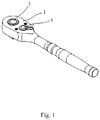
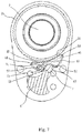
- the ratchet wrench of the present invention comprises a body 1, a driving member 2, a stopping member 3, a switching member 6, and an elastic abutting assembly 7.
- the body 1 is provided with a first chamber 11 and a second chamber 12 communicating with the first chamber 11.
- the driving member 2 is rotatably disposed in the first chamber 11 and is circumferentially provided with an annular toothed part 21 along the outer peripheral surface.
- the stopping assembly 3 comprises a first stopping member 4 and a second stopping member 5 which are disposed in the first chamber 11, are at least partially overlapped with each other, and can slide and swing relative to each other.
- the first stopping member 4 is provided with a first ratchet part 41, and a side of the first stopping member 4 opposite the first ratchet part 41 is provided with a first abutment part 42 and a first pressing part 43, the first abutment part 42 being adjacent to the first ratchet part 41 and the first pressing part 43 being away from the first ratchet part 41.
- the second stopping member 5 is provided with a second ratchet part 51, and a side of the second stopping member 5 opposite the second ratchet part 51 is provided with a second abutment part 52 and a second pressing part 53, the second abutment part 52 being adjacent to the second ratchet part 51 and the second pressing part 53 being away from the second ratchet part 51.
- the switching member 6 is rotatably disposed in the second chamber 12, is provided with a hole 61 in the radial direction, and is selectively rotated to a first position or a second position.
- the elastic abutting assembly 7 in the present embodiment comprises an elastic member 71 and an abutting block 72, the elastic member 71 being elastically urged between the switching member 6 and the abutting block 72 such that the abutting block 72 normally abuts in a direction away from the switching member 6, and the abutting block 72 causes the first stopping member 4 and second stopping member 5 to normally abut against the annular toothed part 21.
- the elastic abutting assembly 7 abutting against the second pressing part 53 will cause the second ratchet part 51 to slide and swing in a direction away from the annular toothed part 21, at which point the driving member 2 can only rotate in an anticlockwise direction and not in a clockwise direction. Therefore, the second ratchet part 51 will not interfere with the driving member 2 rotating in this anticlockwise direction, and the driving member 2 is able to smoothly achieve an idling effect. As depicted in Fig. 6 and Fig.
- the elastic abutting assembly 7 when the switching member 6 is rotated from said first position to said second position, the elastic abutting assembly 7 abuts against the second abutment part 52 so that the second ratchet part 51 abuts against the annular toothed part 21, and the elastic abutting assembly 7 also abuts against the first pressing part 43 of the first stopping member 4 so as to cause the first ratchet part 41 to move in a direction away from the annular toothed part 21 and not become engaged therewith.
- the elastic abutting assembly 7 abutting against the first pressing part 43 will cause the first ratchet part 41 to slide and swing in a direction away from the annular toothed part 21, at which point the driving member 2 can only rotate in a clockwise direction and not in an anticlockwise direction. Therefore, the first ratchet part 41 will not interfere with the driving member 2 rotating in this clockwise direction, and the driving member 2 can likewise smoothly achieve an idling effect.
- the ratchet wrench of the present invention acts so that the driving member can only engage with either the first ratchet part 41 or the second ratchet part 51 at any one time, thus allowing the driving member 2 to smoothly maintain one-way idling, while also avoiding jamming of the driving member 2 with the first ratchet part 41 or second ratchet part 51 leading to the switching member 6 being unable to smoothly switch positions.
- the first stopping member 4 in the present embodiment comprises a first ratchet block 44 and a first pin 45 which are connected to each other, wherein the first ratchet part 41 is disposed on the first ratchet block 44.
- the second stopping member 5 comprises a second ratchet block 54 and a second pin 55 which are connected to each other, wherein the second ratchet part 51 is disposed on the second ratchet block 54.
- the first abutment part 42 and the first pressing part 43 are disposed on the first pin 45, and the second abutment part 52 and the second pressing part 53 are disposed on the second pin 55.
- the first pin 45 and second pin 55 overlap each other, the first abutment part 42 corresponds to the second pressing part 53 and the first pressing part 43 corresponds to the second abutment part 52.
- the thickness of the first pin 45 and second pin 55 in the present embodiment is equal to one half of the first ratchet block 44, and the thickness of the second ratchet block 54 is the same as that of the first ratchet block 44, so that the centre of gravity of the first stopping member 4 is balanced when engaged with second stopping member 5.
- a gap 31 is formed between the first pin 45 and the second ratchet block 54, and another gap 31 is formed between the second pin 55 and the first ratchet block 44, said gaps 31 allowing sufficient space between the first stopping member 4 and the second stopping member 5 for them to slide and swing relative to each other.
- first ratchet block 44 forms a first groove 46
- second ratchet block 54 forms a second groove 56
- first groove 46 and second groove 56 are arcuate grooves.
- the ends of the first pin 45 and the second pin 55 respectively form a first bent end 47 and a second bent end 57, said first bent end 47 being accommodated in the second groove 56, and said second bent end 57 being accommodated in the first groove 46.
- the shapes of the first bent end 47 and the second bent end 57 correspond to the shapes of the second groove 56 and the first groove 46, such that the first stopping member 4 and the second stopping member 5 are swung against each other without interfering with each other.
- the elastic abutting assembly 7 simultaneously abuts against both the first stopping member 4 and the second stopping member 5
- the first bent end 47 is slightly hooked on the wall of the second groove 56
- the second bent end 57 is similarly hooked on the wall of the first groove 46, such that the first stopping member 4 will not detach from the second stopping member 5, and when the switching member 6 rotates, the first stopping member 4 and the second stopping member 5 move smoothly together.
- the sides of the elastic abutting assembly 7 towards which are oriented a first pin 45A of a first stopping member 4A and a second pin 55A of a second stopping member 5A may be extended with a first flange 48 and a second flange 58, wherein the end of the elastic abutting assembly 7 oriented towards the driving member 2 is sandwiched between said first and second flanges so that the elastic abutting assembly 7 can stably abut against the first pin 45A and second pin 55A in a limiting manner without becoming disengaged.
- a third embodiment of the present invention as compared with the above-described first embodiment, the side of a first pin 45B of a first stopping member 4B which is oriented towards the second pin 55B is provided with a first stud 491 and a first recess 492, and the side of a second pin 45B of a second stopping member 5B which is oriented towards the first pin 45B is provided with a second stud 591 and a second recess 592, wherein the first stud 491 and the second stud 591 are respectively inserted into the second recess 592 and the first recess 492.
- first stud 491 and the second stud 591 are inclined, and the maximum radial dimensions of the first stud 491 and second stud 591 are smaller than the radial dimensions of the first recess 492 and the second recess 592.
- a gap 31 B is formed between the first pin 45B and the second ratchet block 54, and another gap 31B is formed between the second pin 55B and the first ratchet block 44, said gaps 31 similarly allowing sufficient space between first stopping member 4B and the second stopping member 5B for them to slide and swing relative to each other.
- the present embodiment likewise can achieve the effect of having driving member 2 only engaging with either the first ratchet part 41 or the second ratchet part 51 at any one time, thus similarly allowing the driving member 2 to smoothly maintain one-way idling, while also avoiding jamming of the driving member 2 with the first ratchet part 41 or second ratchet part leading to the switching member 6 being unable to smoothly switch positions.
- the remaining structures are the same as in the first embodiment and thus no further description is given herein.
Landscapes
- Engineering & Computer Science (AREA)
- Mechanical Engineering (AREA)
- Transmission Devices (AREA)
- Details Of Spanners, Wrenches, And Screw Drivers And Accessories (AREA)
- Braking Arrangements (AREA)
- Chairs For Special Purposes, Such As Reclining Chairs (AREA)
Claims (10)
- Ratschenschlüssel, umfassend:einen Körper (1), der mit einer ersten Kammer (11) und einer zweiten Kammer (12), die mit der ersten Kammer (11) kommuniziert, versehen istein Antriebsglied (2), das drehbar in der ersten Kammer (11) angeordnet ist, und umfänglich mit einem ringförmigen gezahnten Teil (21) entlang der äußeren peripheren Oberfläche versehen ist;eine Stopperbaugruppe (3), die ein erstes Stopperglied (4, 4A, 4B) und ein zweites Stopperglied (5, 5A, 5B) umfasst, die in der ersten Kammer (11) angeordnet sind, einander mindestens teilweise gegenseitig überlappen, und relativ zu einander verschiebbar und verschwenkbar sind, wobei das erste Stopperglied (4, 4A, 4B) mit einem ersten Ratschenteil (41) versehen ist, eine Seite des ersten Stopperglieds (4, 4A, 4B) gegenüber zu dem ersten Ratschenteil (41) mit einem ersten Anschlagteil (42) und einem ersten Drückteil (43) versehen ist, das erste Anschlagteil (42) zu dem ersten Ratschenteil (41) benachbart ist, und das erste Drückteil (43) von dem ersten Ratschenteil (41) entfernt ist, und wobei das zweite Stopperglied (5, 5A, 5B) mit einem zweiten Ratschenteil (51) versehen ist, eine Seite des zweiten Stopperglieds (5, 5A, 5B) gegenüber zu dem zweiten Ratschenteil (51) mit einem zweiten Anschlagteil (52) und einem zweiten Drückteil (53) versehen ist, das zweite Anschlagteil (52) zu dem zweiten Ratschenteil (51) benachbart ist, und das zweite Drückteil (53) von dem zweiten Ratschenteil (51) entfernt ist; undein Schaltglied (6), das drehbar in der zweiten Kammer (12) angeordnet ist, wobei das Schaltglied (6) mit einem Loch (61) in der radialen Richtung versehen ist und wahlweise zu einer ersten Position oder einer zweiten Position gedreht werden kann;gekennzeichnet durcheine elastische Anschlagbaugruppe (7), von der ein Ende in dem Loch (61) des Schaltglieds (6) aufgenommen ist, während das andere Ende gegen das erste Stopperglied (4, 4A, 4B) und das zweite Stopperglied (5, 5A, 5B) auf eine gemeinsam begrenzende Weise anschlägt, und das erste Stopperglied (4, 4A, 4B) und das zweite Stopperglied (5, 5A, 5B) in der Richtung des ringförmigen gezahnten Teils (21) anschlagen;wobei, wenn das Schaltglied (6) zu der ersten Position gedreht ist, die elastische Anschlagbaugruppe (7) gegen das erste Anschlagteil (42) anschlägt, so dass das erste Ratschenteil (41) gegen das ringförmige gezahnte Teil (21) anschlägt, und die elastische Anschlagbaugruppe (7) ebenfalls derart gegen das zweite Drückteil (53) des zweiten Stopperglieds (5, 5A, 5B) in anschlägt, dass das zweite Ratschenteil (51) dazu gebracht wird, sich in eine Richtung weg von dem ringförmigen gezahnten Teil (21) zu bewegen und mit diesem nicht in Eingriff zu gelangen;und wenn das Schaltglied (6) zu der zweiten Position gedreht ist, die elastische Anschlagbaugruppe (7) gegen das zweite Anschlagteil (52) anschlägt, so dass das zweite Ratschenteil (51) gegen das ringförmige gezahnte Teil (21) anschlägt, und die elastische Anschlagbaugruppe (7) ebenfalls derart gegen das erste Drückteil (43) des ersten Stopperglieds (4, 4A, 4B) in anschlägt, dass das erste Ratschenteil (41) dazu gebracht wird, sich in eine Richtung weg von dem ringförmigen gezahnten Teil (21) zu bewegen und mit diesem nicht in Eingriff zu gelangen.
- Ratschenschlüssel nach Anspruch 1, wobei das erste Stopperglied (4, 4A, 4B) einen ersten Ratschenblock (44) und einen ersten Stift (45, 45A, 45B) umfasst, die mit einander verbunden sind, wobei das erste Ratschenteil (41) auf dem ersten Ratschenblock (44) angeordnet ist, und das zweite Stopperglied (5, 5A, 5B) einen zweiten Ratschenblock (54) und einen zweiten Stift (55, 55A, 55B) umfasst, die mit einander verbunden sind, wobei das zweite Ratschenteil (51) auf dem zweiten Ratschenblock (54) angeordnet ist, wobei das erste Anschlagteil (42) und das erste Drückteil (43) auf dem ersten Stift (45, 45A, 45B) angeordnet sind, das zweite Anschlagteil (52) und das zweite Drückteil (53) auf dem zweiten Stift (55, 55A, 55B) angeordnet sind, der erste Stift (45, 45A, 45B) und der zweite Stift (55, 55A, 55B) einander gegenseitig überlappen, das erste Anschlagteil (42) dem zweiten Drückteil (53) entspricht, und das erste Drückteil (43) dem zweiten Anschlagteil (52) entspricht.
- Ratschenschlüssel nach Anspruch 2, wobei ein Spalt (31, 31B) zwischen dem ersten Stift (45, 45A, 45B) und dem zweiten Ratschenblock (54) gebildet ist, und ein weiterer Spalt (31, 31B) zwischen dem zweiten Stift (55, 55A, 55B) und dem ersten Ratschenblock (44) gebildet ist.
- Ratschenschlüssel nach Anspruch 2, wobei der erste Ratschenblock (44) eine erste Nut (46) bildet, der zweite Ratschenblock (54) eine zweite Nut (56) bildet, die erste Nut (46) und die zweite Nut (56) bogenförmige Nuten sind, die Enden des ersten Stifts (45, 45A, 45B) und des zweiten Stifts (55, 55A, 55B) jeweils ein erstes gebogenes Ende (47) und ein zweites gebogenes Ende (57) bilden, das erste gebogene Ende (47) in der zweiten Nut (56) untergebracht ist, das zweite gebogene Ende (57) in der ersten Nut (46) untergebracht ist, und die Formen des ersten gebogenen Endes (47) und des zweiten gebogenen Endes (57) den Formen der zweiten Nut (56) und der ersten Nut (46) entsprechen.
- Ratschenschlüssel nach Anspruch 2, wobei die Dicke des ersten Stifts (45, 45A, 45B) und des zweiten Stifts (55, 55A, 55B) gleich einer Hälfte des ersten Ratschenblocks (44) ist, und die Dicke des zweiten Ratschenblocks (54) dieselbe ist, wie die des ersten Ratschenblocks (44).
- Ratschenschlüssel nach Anspruch 2, wobei die Seiten der elastischen Anschlagbaugruppe (7), zu denen der erste Stift (45, 45A, 45B) und der zweite Stift (55, 55A, 55B) hin orientiert sind, mit einem ersten Flansch (48) und einem zweiten Flansch (58) erweitert sein können, wobei das Ende der elastischen Anschlagbaugruppe (7), das zu dem Antriebsglied (2) hin orientiert ist, zwischen den ersten und zweiten Flanschen (48, 58) zwischengesetzt ist.
- Ratschenschlüssel nach Anspruch 2, wobei die Seite des ersten Stifts (45, 45A, 45B), die zu dem zweiten Stift (55, 55A, 55B) hin orientiert ist, mit einem ersten Zapfen (491) und einer ersten Aussparung (492) versehen ist, und die Seite des zweiten Stifts, die zu dem ersten Stift (45, 45A, 45B) hin orientiert ist, mit einem zweiten Zapfen (591) und einer zweiten Aussparung (592) versehen ist, wobei der erste Zapfen (491) und der zweite Zapfen (591) jeweils in die zweite Aussparung (592) und die erste Aussparung (492) eingesetzt sind.
- Ratschenschlüssel nach Anspruch 7, wobei der erste Zapfen (491) und der zweite Zapfen (591) geneigt sind, und die maximalen radialen Abmessungen des ersten Zapfens (491) und des zweiten Zapfens (591) geringer sind, als die radialen Abmessungen der ersten Aussparung (492) und der zweiten Aussparung (592).
- Ratschenschlüssel nach Anspruch 3, wobei: der erste Ratschenblock (44) eine erste Nut (46) bildet, der zweite Ratschenblock (54) eine zweite Nut (56) bildet, die erste Nut (46) und die zweite Nut (56) bogenförmige Nuten sind, die Enden des ersten Stifts (45, 45A, 45B) und des zweiten Stift (55, 55A, 55B) jeweils ein erstes gebogenes Ende (47) und ein zweites gebogenes Ende (57) bilden, das erste gebogene Ende (47) in der zweiten Nut (56) untergebracht ist, das zweite gebogene Ende (57) in der ersten Nut (46) untergebracht ist, und die Formen des ersten gebogenen Endes (47) und des zweiten gebogenen Endes (57) den Formen der zweiten Nut (56) und der ersten Nut (46) entsprechen; wobei die Dicke des ersten Stifts (45, 45A, 45B) und des zweiten Stifts (55, 55A, 55B) gleich einer Hälfte des ersten Ratschenblocks (44) ist, und die Dicke des zweiten Ratschenblocks (54) dieselbe ist, wie die des ersten Ratschenblocks (44); und die Seiten der elastischen Anschlagbaugruppe (7), zu denen der erste Stift (45, 45A, 45B) und der zweite Stift (55, 55A, 55B) hin orientiert sind, mit einem ersten Flansch (48) und einem zweiten Flansch (58) erweitert sein können, wobei das Ende der elastischen Anschlagbaugruppe (7), das zu dem Antriebsglied (2) hin orientiert ist, zwischen den ersten und zweiten Flanschen (48, 58) zwischengesetzt ist.
- Ratschenschlüssel nach Anspruch 3, wobei: wobei die Dicke des ersten Stifts (45, 45A, 45B) und des zweiten Stifts (55, 55A, 55B) gleich einer Hälfte des ersten Ratschenblocks (44) ist, und die Dicke des zweiten Ratschenblocks (54) dieselbe ist, wie die des ersten Ratschenblocks (44); die Seite des ersten Stifts (45, 45A, 45B), die zu dem zweiten Stift (55, 55A, 55B) hin orientiert ist, mit einem ersten Zapfen (491) und einer ersten Aussparung (492) versehen ist, und die Seite des zweiten Stifts (55, 55A, 55B), die zu dem ersten Stift (45, 45A, 45B) hin orientiert ist, mit einem zweiten Zapfen (591) und einer zweiten Aussparung (592) versehen ist, wobei der erste Zapfen (491) und der zweite Zapfen (591) jeweils in die zweite Aussparung (592) und die erste Aussparung (492) eingesetzt sind; und der erste Zapfen (491) und der zweite Zapfen (591) geneigt sind, und die maximalen radialen Abmessungen des ersten Zapfens (491) und des zweiten Zapfens (591) geringer sind, als die radialen Abmessungen der ersten Aussparung (492) und der zweiten Aussparung (592).
Applications Claiming Priority (1)
| Application Number | Priority Date | Filing Date | Title |
|---|---|---|---|
| TW105136259A TWI586492B (zh) | 2016-11-08 | 2016-11-08 | 棘輪扳手 |
Publications (2)
| Publication Number | Publication Date |
|---|---|
| EP3318365A1 EP3318365A1 (de) | 2018-05-09 |
| EP3318365B1 true EP3318365B1 (de) | 2019-09-04 |
Family
ID=58606145
Family Applications (1)
| Application Number | Title | Priority Date | Filing Date |
|---|---|---|---|
| EP17167618.2A Active EP3318365B1 (de) | 2016-11-08 | 2017-04-21 | Ratschenschlüssel |
Country Status (4)
| Country | Link |
|---|---|
| US (1) | US10414028B2 (de) |
| EP (1) | EP3318365B1 (de) |
| CN (1) | CN108058119B (de) |
| TW (1) | TWI586492B (de) |
Cited By (1)
| Publication number | Priority date | Publication date | Assignee | Title |
|---|---|---|---|---|
| EP3408055B1 (de) * | 2016-01-27 | 2024-04-10 | Wera Werkzeuge GmbH | Schraubwerkzeug mit richtungsumschaltbarem freilaufgesperre |
Families Citing this family (9)
| Publication number | Priority date | Publication date | Assignee | Title |
|---|---|---|---|---|
| USD967689S1 (en) * | 2020-04-27 | 2022-10-25 | Shih-Hao Lai | Wrench |
| USD1007985S1 (en) * | 2020-09-30 | 2023-12-19 | Re-Dai Precision Tools Co., Ltd. | Switcher of reversible ratchet wrench |
| USD1000922S1 (en) * | 2021-01-07 | 2023-10-10 | Chia-Yu Chen | Switch knob for ratchet wrench |
| USD1022639S1 (en) * | 2021-05-27 | 2024-04-16 | Hong Ann Tool Industries Co., Ltd. | Ratchet gear |
| TWI791266B (zh) * | 2021-08-19 | 2023-02-01 | 真好產業有限公司 | 棘輪扳手 |
| TWI779780B (zh) * | 2021-08-19 | 2022-10-01 | 真好產業有限公司 | 棘輪扳手 |
| US20250229387A1 (en) * | 2024-01-16 | 2025-07-17 | Harbor Freight Tools Usa, Inc. | Ratchet Tool Including Pawl with Biasing Effect |
| USD1122706S1 (en) * | 2024-02-16 | 2026-04-21 | Stanley Black & Decker Inc. | Gear for a hand tool |
| USD1123549S1 (en) * | 2024-02-16 | 2026-04-28 | Stanley Black & Decker, Inc. | Gear for a hand tool |
Family Cites Families (10)
| Publication number | Priority date | Publication date | Assignee | Title |
|---|---|---|---|---|
| US5782147A (en) * | 1996-11-21 | 1998-07-21 | Hand Tool Design Corporation | Ratchet wrench having two-pawl action |
| US6918323B2 (en) * | 2002-11-01 | 2005-07-19 | Easco Hand Tools Inc. | Reversible ratcheting tool with improved pawl |
| TWI252143B (en) * | 2004-05-19 | 2006-04-01 | Hou-Fei Hu | Three-stepped ratchet wrench |
| TW201422379A (zh) * | 2012-12-14 | 2014-06-16 | Pard Hardware Ind Co Ltd | 棘輪扳手的轉向裝置改良 |
| US9643298B2 (en) * | 2013-01-18 | 2017-05-09 | Hangzhou Great Star Tools Co., Ltd | Thin bi-directional ratchet wrench |
| US9038505B2 (en) * | 2013-07-28 | 2015-05-26 | Ya-Lan He | Wrench |
| TW201507818A (zh) * | 2013-08-30 | 2015-03-01 | New Way Tools Co Ltd | 可更小角度轉動之換向棘輪扳手 |
| TWI529034B (zh) | 2014-02-06 | 2016-04-11 | Cheng-Pu Yang | Ratchet wrench structure |
| TWM485119U (zh) * | 2014-03-13 | 2014-09-01 | Kun-Zhe Wu | 換向棘輪扳手 |
| CN205614555U (zh) * | 2016-01-14 | 2016-10-05 | 陈井 | 小角度棘轮扳手 |
-
2016
- 2016-11-08 TW TW105136259A patent/TWI586492B/zh not_active IP Right Cessation
- 2016-11-17 CN CN201611010830.8A patent/CN108058119B/zh not_active Expired - Fee Related
-
2017
- 2017-04-21 EP EP17167618.2A patent/EP3318365B1/de active Active
- 2017-04-25 US US15/496,424 patent/US10414028B2/en active Active
Non-Patent Citations (1)
| Title |
|---|
| None * |
Cited By (1)
| Publication number | Priority date | Publication date | Assignee | Title |
|---|---|---|---|---|
| EP3408055B1 (de) * | 2016-01-27 | 2024-04-10 | Wera Werkzeuge GmbH | Schraubwerkzeug mit richtungsumschaltbarem freilaufgesperre |
Also Published As
| Publication number | Publication date |
|---|---|
| CN108058119B (zh) | 2019-11-15 |
| US20180126519A1 (en) | 2018-05-10 |
| TW201817548A (zh) | 2018-05-16 |
| EP3318365A1 (de) | 2018-05-09 |
| US10414028B2 (en) | 2019-09-17 |
| CN108058119A (zh) | 2018-05-22 |
| TWI586492B (zh) | 2017-06-11 |
Similar Documents
| Publication | Publication Date | Title |
|---|---|---|
| EP3318365B1 (de) | Ratschenschlüssel | |
| US9562575B2 (en) | Ratchet type one-way clutch | |
| US12370653B2 (en) | Dual pawl ratchet mechanism | |
| US9862076B2 (en) | Pawl control device for ratchet wrench | |
| JP2016511382A (ja) | 変速機用パーキングロック機構 | |
| US20180079055A1 (en) | Wrench | |
| TW202009393A (zh) | 二段式萬向工具 | |
| US20190099865A1 (en) | Ratchet wrench | |
| US11253981B2 (en) | Ratchet wrench | |
| KR101911154B1 (ko) | 토크 리미터 | |
| US20180361545A1 (en) | Ratchet Gear Reinforcing Ring | |
| JP2015145721A5 (de) | ||
| US20050016332A1 (en) | Wrench combination | |
| WO2017077335A1 (en) | Ratchet wrenches | |
| JP5030488B2 (ja) | 一方向クラッチユニット | |
| TW202019625A (zh) | 棘輪扳手 | |
| US20140166421A1 (en) | Ratchet bicycle hub assembly | |
| US8806987B2 (en) | Steering device for a ratchet screwdriver | |
| US20200180121A1 (en) | Reversible wrench | |
| JP2021067286A (ja) | 逆入力防止クラッチ | |
| TW202212072A (zh) | 具有換向結構的套筒扳手 | |
| TWM459958U (zh) | 具有改良換向結構之棘輪扳手 | |
| US9205537B2 (en) | Detachable ratchet wrench | |
| JP6906581B2 (ja) | 逆入力遮断クラッチ | |
| WO2008056995A2 (en) | Improved pawl for a one-way clutch |
Legal Events
| Date | Code | Title | Description |
|---|---|---|---|
| PUAI | Public reference made under article 153(3) epc to a published international application that has entered the european phase |
Free format text: ORIGINAL CODE: 0009012 |
|
| STAA | Information on the status of an ep patent application or granted ep patent |
Free format text: STATUS: THE APPLICATION HAS BEEN PUBLISHED |
|
| AK | Designated contracting states |
Kind code of ref document: A1 Designated state(s): AL AT BE BG CH CY CZ DE DK EE ES FI FR GB GR HR HU IE IS IT LI LT LU LV MC MK MT NL NO PL PT RO RS SE SI SK SM TR |
|
| AX | Request for extension of the european patent |
Extension state: BA ME |
|
| STAA | Information on the status of an ep patent application or granted ep patent |
Free format text: STATUS: REQUEST FOR EXAMINATION WAS MADE |
|
| 17P | Request for examination filed |
Effective date: 20181101 |
|
| RBV | Designated contracting states (corrected) |
Designated state(s): AL AT BE BG CH CY CZ DE DK EE ES FI FR GB GR HR HU IE IS IT LI LT LU LV MC MK MT NL NO PL PT RO RS SE SI SK SM TR |
|
| STAA | Information on the status of an ep patent application or granted ep patent |
Free format text: STATUS: EXAMINATION IS IN PROGRESS |
|
| 17Q | First examination report despatched |
Effective date: 20190124 |
|
| GRAP | Despatch of communication of intention to grant a patent |
Free format text: ORIGINAL CODE: EPIDOSNIGR1 |
|
| STAA | Information on the status of an ep patent application or granted ep patent |
Free format text: STATUS: GRANT OF PATENT IS INTENDED |
|
| INTG | Intention to grant announced |
Effective date: 20190529 |
|
| GRAS | Grant fee paid |
Free format text: ORIGINAL CODE: EPIDOSNIGR3 |
|
| GRAA | (expected) grant |
Free format text: ORIGINAL CODE: 0009210 |
|
| STAA | Information on the status of an ep patent application or granted ep patent |
Free format text: STATUS: THE PATENT HAS BEEN GRANTED |
|
| AK | Designated contracting states |
Kind code of ref document: B1 Designated state(s): AL AT BE BG CH CY CZ DE DK EE ES FI FR GB GR HR HU IE IS IT LI LT LU LV MC MK MT NL NO PL PT RO RS SE SI SK SM TR |
|
| REG | Reference to a national code |
Ref country code: GB Ref legal event code: FG4D |
|
| REG | Reference to a national code |
Ref country code: CH Ref legal event code: EP |
|
| REG | Reference to a national code |
Ref country code: AT Ref legal event code: REF Ref document number: 1174712 Country of ref document: AT Kind code of ref document: T Effective date: 20190915 |
|
| REG | Reference to a national code |
Ref country code: DE Ref legal event code: R096 Ref document number: 602017006647 Country of ref document: DE |
|
| REG | Reference to a national code |
Ref country code: IE Ref legal event code: FG4D |
|
| REG | Reference to a national code |
Ref country code: NL Ref legal event code: MP Effective date: 20190904 |
|
| REG | Reference to a national code |
Ref country code: LT Ref legal event code: MG4D |
|
| PG25 | Lapsed in a contracting state [announced via postgrant information from national office to epo] |
Ref country code: SE Free format text: LAPSE BECAUSE OF FAILURE TO SUBMIT A TRANSLATION OF THE DESCRIPTION OR TO PAY THE FEE WITHIN THE PRESCRIBED TIME-LIMIT Effective date: 20190904 Ref country code: LT Free format text: LAPSE BECAUSE OF FAILURE TO SUBMIT A TRANSLATION OF THE DESCRIPTION OR TO PAY THE FEE WITHIN THE PRESCRIBED TIME-LIMIT Effective date: 20190904 Ref country code: HR Free format text: LAPSE BECAUSE OF FAILURE TO SUBMIT A TRANSLATION OF THE DESCRIPTION OR TO PAY THE FEE WITHIN THE PRESCRIBED TIME-LIMIT Effective date: 20190904 Ref country code: FI Free format text: LAPSE BECAUSE OF FAILURE TO SUBMIT A TRANSLATION OF THE DESCRIPTION OR TO PAY THE FEE WITHIN THE PRESCRIBED TIME-LIMIT Effective date: 20190904 Ref country code: BG Free format text: LAPSE BECAUSE OF FAILURE TO SUBMIT A TRANSLATION OF THE DESCRIPTION OR TO PAY THE FEE WITHIN THE PRESCRIBED TIME-LIMIT Effective date: 20191204 Ref country code: NO Free format text: LAPSE BECAUSE OF FAILURE TO SUBMIT A TRANSLATION OF THE DESCRIPTION OR TO PAY THE FEE WITHIN THE PRESCRIBED TIME-LIMIT Effective date: 20191204 |
|
| PG25 | Lapsed in a contracting state [announced via postgrant information from national office to epo] |
Ref country code: AL Free format text: LAPSE BECAUSE OF FAILURE TO SUBMIT A TRANSLATION OF THE DESCRIPTION OR TO PAY THE FEE WITHIN THE PRESCRIBED TIME-LIMIT Effective date: 20190904 Ref country code: ES Free format text: LAPSE BECAUSE OF FAILURE TO SUBMIT A TRANSLATION OF THE DESCRIPTION OR TO PAY THE FEE WITHIN THE PRESCRIBED TIME-LIMIT Effective date: 20190904 Ref country code: RS Free format text: LAPSE BECAUSE OF FAILURE TO SUBMIT A TRANSLATION OF THE DESCRIPTION OR TO PAY THE FEE WITHIN THE PRESCRIBED TIME-LIMIT Effective date: 20190904 Ref country code: LV Free format text: LAPSE BECAUSE OF FAILURE TO SUBMIT A TRANSLATION OF THE DESCRIPTION OR TO PAY THE FEE WITHIN THE PRESCRIBED TIME-LIMIT Effective date: 20190904 Ref country code: GR Free format text: LAPSE BECAUSE OF FAILURE TO SUBMIT A TRANSLATION OF THE DESCRIPTION OR TO PAY THE FEE WITHIN THE PRESCRIBED TIME-LIMIT Effective date: 20191205 |
|
| REG | Reference to a national code |
Ref country code: AT Ref legal event code: MK05 Ref document number: 1174712 Country of ref document: AT Kind code of ref document: T Effective date: 20190904 |
|
| PG25 | Lapsed in a contracting state [announced via postgrant information from national office to epo] |
Ref country code: IT Free format text: LAPSE BECAUSE OF FAILURE TO SUBMIT A TRANSLATION OF THE DESCRIPTION OR TO PAY THE FEE WITHIN THE PRESCRIBED TIME-LIMIT Effective date: 20190904 Ref country code: RO Free format text: LAPSE BECAUSE OF FAILURE TO SUBMIT A TRANSLATION OF THE DESCRIPTION OR TO PAY THE FEE WITHIN THE PRESCRIBED TIME-LIMIT Effective date: 20190904 Ref country code: PT Free format text: LAPSE BECAUSE OF FAILURE TO SUBMIT A TRANSLATION OF THE DESCRIPTION OR TO PAY THE FEE WITHIN THE PRESCRIBED TIME-LIMIT Effective date: 20200106 Ref country code: AT Free format text: LAPSE BECAUSE OF FAILURE TO SUBMIT A TRANSLATION OF THE DESCRIPTION OR TO PAY THE FEE WITHIN THE PRESCRIBED TIME-LIMIT Effective date: 20190904 Ref country code: NL Free format text: LAPSE BECAUSE OF FAILURE TO SUBMIT A TRANSLATION OF THE DESCRIPTION OR TO PAY THE FEE WITHIN THE PRESCRIBED TIME-LIMIT Effective date: 20190904 Ref country code: EE Free format text: LAPSE BECAUSE OF FAILURE TO SUBMIT A TRANSLATION OF THE DESCRIPTION OR TO PAY THE FEE WITHIN THE PRESCRIBED TIME-LIMIT Effective date: 20190904 Ref country code: PL Free format text: LAPSE BECAUSE OF FAILURE TO SUBMIT A TRANSLATION OF THE DESCRIPTION OR TO PAY THE FEE WITHIN THE PRESCRIBED TIME-LIMIT Effective date: 20190904 |
|
| PG25 | Lapsed in a contracting state [announced via postgrant information from national office to epo] |
Ref country code: CZ Free format text: LAPSE BECAUSE OF FAILURE TO SUBMIT A TRANSLATION OF THE DESCRIPTION OR TO PAY THE FEE WITHIN THE PRESCRIBED TIME-LIMIT Effective date: 20190904 Ref country code: IS Free format text: LAPSE BECAUSE OF FAILURE TO SUBMIT A TRANSLATION OF THE DESCRIPTION OR TO PAY THE FEE WITHIN THE PRESCRIBED TIME-LIMIT Effective date: 20200224 Ref country code: SM Free format text: LAPSE BECAUSE OF FAILURE TO SUBMIT A TRANSLATION OF THE DESCRIPTION OR TO PAY THE FEE WITHIN THE PRESCRIBED TIME-LIMIT Effective date: 20190904 Ref country code: SK Free format text: LAPSE BECAUSE OF FAILURE TO SUBMIT A TRANSLATION OF THE DESCRIPTION OR TO PAY THE FEE WITHIN THE PRESCRIBED TIME-LIMIT Effective date: 20190904 |
|
| REG | Reference to a national code |
Ref country code: DE Ref legal event code: R097 Ref document number: 602017006647 Country of ref document: DE |
|
| PLBE | No opposition filed within time limit |
Free format text: ORIGINAL CODE: 0009261 |
|
| STAA | Information on the status of an ep patent application or granted ep patent |
Free format text: STATUS: NO OPPOSITION FILED WITHIN TIME LIMIT |
|
| PG2D | Information on lapse in contracting state deleted |
Ref country code: IS |
|
| PG25 | Lapsed in a contracting state [announced via postgrant information from national office to epo] |
Ref country code: DK Free format text: LAPSE BECAUSE OF FAILURE TO SUBMIT A TRANSLATION OF THE DESCRIPTION OR TO PAY THE FEE WITHIN THE PRESCRIBED TIME-LIMIT Effective date: 20190904 Ref country code: IS Free format text: LAPSE BECAUSE OF FAILURE TO SUBMIT A TRANSLATION OF THE DESCRIPTION OR TO PAY THE FEE WITHIN THE PRESCRIBED TIME-LIMIT Effective date: 20200105 |
|
| 26N | No opposition filed |
Effective date: 20200605 |
|
| PG25 | Lapsed in a contracting state [announced via postgrant information from national office to epo] |
Ref country code: SI Free format text: LAPSE BECAUSE OF FAILURE TO SUBMIT A TRANSLATION OF THE DESCRIPTION OR TO PAY THE FEE WITHIN THE PRESCRIBED TIME-LIMIT Effective date: 20190904 |
|
| PG25 | Lapsed in a contracting state [announced via postgrant information from national office to epo] |
Ref country code: MC Free format text: LAPSE BECAUSE OF FAILURE TO SUBMIT A TRANSLATION OF THE DESCRIPTION OR TO PAY THE FEE WITHIN THE PRESCRIBED TIME-LIMIT Effective date: 20190904 |
|
| REG | Reference to a national code |
Ref country code: CH Ref legal event code: PL |
|
| PG25 | Lapsed in a contracting state [announced via postgrant information from national office to epo] |
Ref country code: LU Free format text: LAPSE BECAUSE OF NON-PAYMENT OF DUE FEES Effective date: 20200421 Ref country code: CH Free format text: LAPSE BECAUSE OF NON-PAYMENT OF DUE FEES Effective date: 20200430 Ref country code: LI Free format text: LAPSE BECAUSE OF NON-PAYMENT OF DUE FEES Effective date: 20200430 Ref country code: FR Free format text: LAPSE BECAUSE OF NON-PAYMENT OF DUE FEES Effective date: 20200430 |
|
| REG | Reference to a national code |
Ref country code: BE Ref legal event code: MM Effective date: 20200430 |
|
| PG25 | Lapsed in a contracting state [announced via postgrant information from national office to epo] |
Ref country code: BE Free format text: LAPSE BECAUSE OF NON-PAYMENT OF DUE FEES Effective date: 20200430 |
|
| PG25 | Lapsed in a contracting state [announced via postgrant information from national office to epo] |
Ref country code: IE Free format text: LAPSE BECAUSE OF NON-PAYMENT OF DUE FEES Effective date: 20200421 |
|
| PGFP | Annual fee paid to national office [announced via postgrant information from national office to epo] |
Ref country code: GB Payment date: 20210324 Year of fee payment: 5 |
|
| PGFP | Annual fee paid to national office [announced via postgrant information from national office to epo] |
Ref country code: DE Payment date: 20210323 Year of fee payment: 5 |
|
| PG25 | Lapsed in a contracting state [announced via postgrant information from national office to epo] |
Ref country code: TR Free format text: LAPSE BECAUSE OF FAILURE TO SUBMIT A TRANSLATION OF THE DESCRIPTION OR TO PAY THE FEE WITHIN THE PRESCRIBED TIME-LIMIT Effective date: 20190904 Ref country code: MT Free format text: LAPSE BECAUSE OF FAILURE TO SUBMIT A TRANSLATION OF THE DESCRIPTION OR TO PAY THE FEE WITHIN THE PRESCRIBED TIME-LIMIT Effective date: 20190904 Ref country code: CY Free format text: LAPSE BECAUSE OF FAILURE TO SUBMIT A TRANSLATION OF THE DESCRIPTION OR TO PAY THE FEE WITHIN THE PRESCRIBED TIME-LIMIT Effective date: 20190904 |
|
| PG25 | Lapsed in a contracting state [announced via postgrant information from national office to epo] |
Ref country code: MK Free format text: LAPSE BECAUSE OF FAILURE TO SUBMIT A TRANSLATION OF THE DESCRIPTION OR TO PAY THE FEE WITHIN THE PRESCRIBED TIME-LIMIT Effective date: 20190904 |
|
| REG | Reference to a national code |
Ref country code: DE Ref legal event code: R119 Ref document number: 602017006647 Country of ref document: DE |
|
| GBPC | Gb: european patent ceased through non-payment of renewal fee |
Effective date: 20220421 |
|
| PG25 | Lapsed in a contracting state [announced via postgrant information from national office to epo] |
Ref country code: GB Free format text: LAPSE BECAUSE OF NON-PAYMENT OF DUE FEES Effective date: 20220421 Ref country code: DE Free format text: LAPSE BECAUSE OF NON-PAYMENT OF DUE FEES Effective date: 20221103 |