EP3318370A2 - System und verfahren zur herstellung und steuerung dafür - Google Patents
System und verfahren zur herstellung und steuerung dafür Download PDFInfo
- Publication number
- EP3318370A2 EP3318370A2 EP17001776.8A EP17001776A EP3318370A2 EP 3318370 A2 EP3318370 A2 EP 3318370A2 EP 17001776 A EP17001776 A EP 17001776A EP 3318370 A2 EP3318370 A2 EP 3318370A2
- Authority
- EP
- European Patent Office
- Prior art keywords
- robot
- manufacture process
- tool
- power source
- controller
- Prior art date
- Legal status (The legal status is an assumption and is not a legal conclusion. Google has not performed a legal analysis and makes no representation as to the accuracy of the status listed.)
- Ceased
Links
Images


Classifications
-
- G—PHYSICS
- G05—CONTROLLING; REGULATING
- G05B—CONTROL OR REGULATING SYSTEMS IN GENERAL; FUNCTIONAL ELEMENTS OF SUCH SYSTEMS; MONITORING OR TESTING ARRANGEMENTS FOR SUCH SYSTEMS OR ELEMENTS
- G05B19/00—Program-control systems
- G05B19/02—Program-control systems electric
- G05B19/18—Numerical control [NC], i.e. automatically operating machines, in particular machine tools, e.g. in a manufacturing environment, so as to execute positioning, movement or co-ordinated operations by means of program data in numerical form
- G05B19/406—Numerical control [NC], i.e. automatically operating machines, in particular machine tools, e.g. in a manufacturing environment, so as to execute positioning, movement or co-ordinated operations by means of program data in numerical form characterised by monitoring or safety
- G05B19/4061—Avoiding collision or forbidden zones
-
- B—PERFORMING OPERATIONS; TRANSPORTING
- B25—HAND TOOLS; PORTABLE POWER-DRIVEN TOOLS; MANIPULATORS
- B25J—MANIPULATORS; CHAMBERS PROVIDED WITH MANIPULATION DEVICES
- B25J11/00—Manipulators not otherwise provided for
- B25J11/005—Manipulators for mechanical processing tasks
-
- B—PERFORMING OPERATIONS; TRANSPORTING
- B25—HAND TOOLS; PORTABLE POWER-DRIVEN TOOLS; MANIPULATORS
- B25J—MANIPULATORS; CHAMBERS PROVIDED WITH MANIPULATION DEVICES
- B25J13/00—Controls for manipulators
-
- B—PERFORMING OPERATIONS; TRANSPORTING
- B25—HAND TOOLS; PORTABLE POWER-DRIVEN TOOLS; MANIPULATORS
- B25J—MANIPULATORS; CHAMBERS PROVIDED WITH MANIPULATION DEVICES
- B25J9/00—Program-controlled manipulators
- B25J9/16—Program controls
- B25J9/1656—Program controls characterised by programming, planning systems for manipulators
- B25J9/1669—Program controls characterised by programming, planning systems for manipulators characterised by special application, e.g. multi-arm co-operation, assembly, grasping
-
- B—PERFORMING OPERATIONS; TRANSPORTING
- B25—HAND TOOLS; PORTABLE POWER-DRIVEN TOOLS; MANIPULATORS
- B25J—MANIPULATORS; CHAMBERS PROVIDED WITH MANIPULATION DEVICES
- B25J9/00—Program-controlled manipulators
- B25J9/16—Program controls
- B25J9/1674—Program controls characterised by safety, monitoring, diagnostic
- B25J9/1676—Avoiding collision or forbidden zones
-
- G—PHYSICS
- G05—CONTROLLING; REGULATING
- G05B—CONTROL OR REGULATING SYSTEMS IN GENERAL; FUNCTIONAL ELEMENTS OF SUCH SYSTEMS; MONITORING OR TESTING ARRANGEMENTS FOR SUCH SYSTEMS OR ELEMENTS
- G05B19/00—Program-control systems
- G05B19/02—Program-control systems electric
- G05B19/04—Program control other than numerical control, i.e. in sequence controllers or logic controllers
- G05B19/042—Program control other than numerical control, i.e. in sequence controllers or logic controllers using digital processors
- G05B19/0423—Input/output
-
- G—PHYSICS
- G05—CONTROLLING; REGULATING
- G05B—CONTROL OR REGULATING SYSTEMS IN GENERAL; FUNCTIONAL ELEMENTS OF SUCH SYSTEMS; MONITORING OR TESTING ARRANGEMENTS FOR SUCH SYSTEMS OR ELEMENTS
- G05B19/00—Program-control systems
- G05B19/02—Program-control systems electric
- G05B19/18—Numerical control [NC], i.e. automatically operating machines, in particular machine tools, e.g. in a manufacturing environment, so as to execute positioning, movement or co-ordinated operations by means of program data in numerical form
- G05B19/4097—Numerical control [NC], i.e. automatically operating machines, in particular machine tools, e.g. in a manufacturing environment, so as to execute positioning, movement or co-ordinated operations by means of program data in numerical form characterised by using design data to control NC machines, e.g. CAD/CAM
-
- G—PHYSICS
- G05—CONTROLLING; REGULATING
- G05B—CONTROL OR REGULATING SYSTEMS IN GENERAL; FUNCTIONAL ELEMENTS OF SUCH SYSTEMS; MONITORING OR TESTING ARRANGEMENTS FOR SUCH SYSTEMS OR ELEMENTS
- G05B19/00—Program-control systems
- G05B19/02—Program-control systems electric
- G05B19/18—Numerical control [NC], i.e. automatically operating machines, in particular machine tools, e.g. in a manufacturing environment, so as to execute positioning, movement or co-ordinated operations by means of program data in numerical form
- G05B19/4097—Numerical control [NC], i.e. automatically operating machines, in particular machine tools, e.g. in a manufacturing environment, so as to execute positioning, movement or co-ordinated operations by means of program data in numerical form characterised by using design data to control NC machines, e.g. CAD/CAM
- G05B19/4099—Surface or curve machining, making three-dimensional [3D] objects, e.g. desktop manufacturing
-
- G—PHYSICS
- G05—CONTROLLING; REGULATING
- G05B—CONTROL OR REGULATING SYSTEMS IN GENERAL; FUNCTIONAL ELEMENTS OF SUCH SYSTEMS; MONITORING OR TESTING ARRANGEMENTS FOR SUCH SYSTEMS OR ELEMENTS
- G05B2219/00—Program-control systems
- G05B2219/30—Nc systems
- G05B2219/39—Robotics, robotics to robotics hand
- G05B2219/39096—Self-collision, internal collison, collision between links of one robot
Definitions
- the invention is related to a system according to claims 1, 7 and 13.
- Devices, systems, and methods consistent with embodiments of the present invention relate to manufacturing (e.g., welding, additive, cutting), and more specifically to offline tools for controlling and code importation of manufacturing protocols.
- this g-code is designed for robots and/or systems that only have three (3) axes of freedom, and there is little or no development on such systems for more complex robots or systems using more than three (3) axes of freedom, up to and beyond, six (6) axes of freedom systems.
- a system in one embodiment, includes a tool configured to be used in a manufacture process on a workpiece.
- the manufacture process may be, for example, a welding process, an additive manufacturing process, or a plasma cutting process.
- the system includes a robot having an arm with an attachment point. The arm is configured to move the tool, when attached to the attachment point, in multiple degrees of freedom during the manufacture process.
- the robot also includes a robot controller configured to control movement of the arm based on motion parameters to perform the manufacture process via the tool.
- the system includes a power source having power electronics. The power electronics are configured to generate electrical output power, based on electrical input parameters, which is provided to the tool during the manufacture process.
- the power source also includes a power source controller configured to receive the motion parameters from the robot controller and adjust the electrical input parameters based on the motion parameters to allow generation of adjusted electrical output power via the power electronics.
- the power source controller is configured to adjust the motion parameters based on the electrical input parameters to generate adjusted motion parameters and provide the adjusted motion parameters to the robot controller.
- the power source controller is configured to adjust, based on the motion parameters, a wire feed speed to generate an adjusted wire feed speed of a consumable electrode used by the tool during the manufacture process.
- the robot controller includes a processor and a non-transitory computer-readable medium storing a path planner component.
- the path planner component includes instructions that when executed by the processor cause the robot controller to generate the motion parameters used to perform the manufacture process while avoiding robot collision conflicts.
- the power source controller includes the path planner component.
- the path planner component includes a reach configuration component that includes data related to physical attributes, motion attributes, kinematics, and limitations of the robot.
- the path planner component also includes a collision avoidance evaluator configured to, using the reach configuration component, determine if an anticipated robot path results in any robot collision conflicts. A user can modify the robot path and/or the manufacture process to avoid the robot collision conflicts with the aid of the collision avoidance evaluator.
- a system in one embodiment, includes a tool configured to be used in a manufacture process on a workpiece.
- the manufacture process may be, for example, a welding process, an additive manufacturing process, or a plasma cutting process.
- the system includes a robot having an arm with an attachment point. The arm is configured to move the tool, when attached to the attachment point, in multiple degrees of freedom during the manufacture process.
- the robot also includes a robot controller configured to control movement of the arm based on motion parameters to perform the manufacture process via the tool.
- the system includes a power source having power electronics. The power electronics are configured to generate electrical output power, based on electrical input parameters, which is provided to the tool during the manufacture process.
- the power source also includes a power source controller configured to receive the motion parameters from the robot controller and adjust the motion parameters based on the electrical input parameters to generate adjusted motion parameters, and provide the adjusted motion parameters to the robot controller.
- the power source controller is configured to adjust the electrical input parameters based on the motion parameters to allow generation of adjusted electrical output power via the power electronics.
- the power source controller is configured to adjust, based on the motion parameters, a wire feed speed to generate an adjusted wire feed speed of a consumable electrode used by the tool during the manufacture process.
- the robot controller includes a processor and a non-transitory computer-readable medium storing a path planner component.
- the path planner component includes instructions that when executed by the processor cause the robot controller to generate the motion parameters used to perform the manufacture process while avoiding robot collision conflicts.
- the power source controller includes the path planner component.
- the path planner component includes a reach configuration component that includes data related to physical attributes, motion attributes, kinematics, and limitations of the robot.
- the path planner component also includes a collision avoidance evaluator configured to, using the reach configuration component, determine if an anticipated robot path results in any robot collision conflicts. A user can modify the robot path and/or the manufacture process to avoid the robot collision conflicts with the aid of the collision avoidance evaluator.
- a system in one embodiment, includes a tool configured to be used in a manufacture process on a workpiece.
- the manufacture process may be, for example, a welding process, an additive manufacturing process, or a plasma cutting process.
- the system includes a robot having an arm with an attachment point. The arm is configured to move the tool, when attached to the attachment point, in multiple degrees of freedom during the manufacture process.
- the robot also includes a robot controller configured to control movement of the arm based on motion parameters to perform the manufacture process via the tool.
- the system includes a power source having power electronics.
- the power electronics are configured to generate electrical output power, based on electrical input parameters, which is provided to the tool during the manufacture process.
- the power source also includes a power source controller.
- the power source controller and the robot controller are configured to communicate information between each other.
- At least one of the robot controller or the power source controller includes a processor and a non-transitory computer-readable medium storing a path planner component.
- the path planner component includes instructions that when executed by the processor cause at least one of the robot controller or the power source controller to generate the motion parameters used to perform the manufacture process while avoiding robot collision conflicts.
- the path planner component includes a reach configuration component that includes data related to physical attributes, motion attributes, kinematics, and limitations of the robot.
- the path planner component also includes a collision avoidance evaluator configured to, using the reach configuration component, determine if an anticipated robot path results in any robot collision conflicts. A user can modify the robot path and/or the manufacture process to avoid the robot collision conflicts with the aid of the collision avoidance evaluator.
- the information communicated between the robot controller and the power source controller may include, for example, robot motion information, a physical weld dimension/characteristic, a material type, a tool angle/orientation, a tool velocity error, a gap condition, a target tool velocity, a motion/weave profile, and a thru-the-arc tracking correction.
- the present disclosure is generally directed to systems and methods of easily allowing higher degrees of freedom manufacturing systems and robots to easily be used for manufacturing complex components and allow for the efficient conversion of a 3D computer model to g-code for higher degrees of freedom systems.
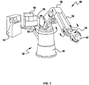
- FIG. 1 shows an exemplary 6 degree of freedom robotic system 100.
- the system 100 includes a computer controller 110 which controls the overall operation of the system.
- the controller 110 can include memory, a user interface, display, a CPU and other components needed to control the system 100 and the motion of the robotic arm assembly.
- a hydraulic unit 120 is used to control hydraulic pressure used to drive the robotic arm assembly 130.
- the robotic arm assembly 130 can be made up of a number of different components which allows the tool attachment point 137 to be moved with 6 degrees of freedom.
- the assembly 130 can have a stand 131, a pivot component for arm sweep 132, a shoulder 133, an elbow 134, an arm 135, a 3-axis tool joint 136 (which allows for yaw, pitch and roll of a tool), and a tool attachment point 137, to which any desired tool can be secured.
- the embodiment of the robotic assembly 130 shown in FIG. 1 is exemplary and other embodiments of the present invention can use any different configurations or constructions so long as the robotic system has four (4) or more degrees of freedom for motion of a tool attached to the tool attachment point 137.
- the tool can be a plasma cutter, welding device, machining tool, additive manufacturing tool, etc.
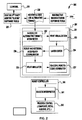
- FIG. 2 a flow diagram of a representative exemplary embodiment of the present invention is depicted.
- the flow 200 depicted represents an exemplary process flow implementing embodiments, methods and systems of the present invention, but is not intended to be limiting.
- the exemplary process begins with the creation of a 3-D model 210 using a known 3-D modeling program, such as CAD.
- This 3-D model can then be supplied to an additive manufacturing (or whatever process being used) slicing software tool for generating g-code for a 3-axis robotic system.
- additive manufacturing or whatever process being used
- These software tools are generally known and need not be described in detail herein. However, as explained previously, these slicing tools are incapable of generating g-code for systems having four (4) or more degrees of freedom.
- the output of the 3-axis slicing tool 220 is provided to an additive g-code application 230 which takes the 3-axis g-code and converts it to g-code to be used with robotic systems containing three (3) or more axes.
- the g-code application 230 can be any known g-code application.
- This application 230 can be run on the system controller 110 (see FIG. 1 ) or any PC, controller, or other computer device capable of performing the functions and tasks described herein.
- a subtractive manufacturing software tool 250 can be used to provide inputs into the g-code application 230.
- the subtractive manufacturing tool 250 can be used to provide machining instructions after the manufacture of a component.
- the g-code application 230 uses the information provided, the g-code application 230 generates and outputs a g-code that is provided to the control program 201 of the robotic system that is used.
- the control program 201 Within, or coupled to, the control program 201 is a process control toolkit 231 that receives the g-code from the application 230. It is noted that while the term "g-code" is used, embodiments of the present invention are not limited to the use of g-code, as other alternative coding languages can be used without departing from the spirit or scope of the present invention.
- the g-code is interpreted by an interpreter 232 and provided to a print visualization component 233 which allows for the original 3D image of the part to be made to be viewed/modeled in 2D via a user screen (not shown).
- the component can be modeled/shown in various ways.
- the part to be made 300 is shown in a layered format being visually comprised of a plurality of layers or individual modules. These layers or modules represent construction passes or blocks of the robot 310 used to make the part 300.
- the layers are constructed across the entire cross-section of the part 300 to be made, while in other embodiments the layers or sections of the part to be made are only a portion of the cross-section of the part to be made at any given height above the substrate. This is depicted simply in FIG. 6A .
- the construction of the model 300 can be in any number and configuration of subcomponents (e.g., layers) as desired. Using this visualization of the model 300, a user can edit, via a layer editor 234, the manufacturing process (e.g., the order of creation of the layers/components as needed).
- the print visualization component 233 can depict the 2D model in various formats, such as using color differentiation to show various aspects of the model 300.
- the component/model 300 can be depicted in a first color 300 (e.g., blue) which shows the entire completed component 300, or at least some component/portion of the component 300.
- the component 300 can be depicted as a wire frame model, for example.
- a layer editor 234 can receive the information from the print visualization component which can allow a user to specifically view and/or change the order of the construction of the model to accommodate tooling needs. This will be discussed further below.
- the toolkit 231 also has a robot and external axes reach configurator 235 which contains information regarding the physical and motion attributes and limitations of the robot 310 to be used to manufacture the component to be built. This information is used by the toolkit 231 to determine whether or not the component/part can be built by the robot 300 without interference or without going beyond its physical/movement capabilities. That is, this information is combined with the information related to the component to be built to determine if the robot 300 can manufacture the part without tool/robot interference. The output of this analysis is provided to a print simulator 236, which simulates the manufacture of the part/component 300 using the information related to the model 300 and from the robot and external axes reach configurator 235.
- the print simulator 236 can visually depict the construction of the model/component 300 - showing the movement of the robot 310 as it completes the entire model 300.
- the user interface of the controller 110 (or other user interface) allows a user to select specific portions or layers of the model 300 to focus on the modeled construction/creation of those layers/sections. After a specific portion of the model 300 is selected the print simulator 236 will model/show the construction of the selected layers/section. In some exemplary embodiments, the actual movement of the robot 310 will be depicted, while in others the movement of the robot and/or the tool is not shown.
- the print simulator 236 can use different visual indicators (e.g., colors) to depict different areas of the model 300 based on its buildability. For example, as explained above, the model 300 is depicted in a first color to show the overall construction of the part to be made. A second color (e.g., green) is used to show the portions of the model 300 (or portion thereof) that can be constructed with the robot system. That is, the second color (second visual indicator) shows the user (via a monitor or user interface) that the indicated portion can be made without an issue. This is depicted in each of FIGS. 3 through 5 as "Region 2".
- a second color e.g., green
- the toolkit 231 also visually depicts regions of the model 300 that cannot be made using a third visual indicator.
- the system can depict regions or portions of the model 300 that cannot be made by the robot system with a third color (e.g., red). This is depicted in FIG. 5 as "Region 3".
- a user could determine - visually before an actual manufacturing process is performed - the manufacturability of the part.
- the layer editor 234 allows a user to change the order of layers or portions of the component to be manufactured to provide an order that allows the part to be made without issue.
- the order at which the portions or layers of the part to be made can be changed to provide an order of construction to allow the part to be completely made by the robot without interference. This is generally shown in FIGS. 6A and 6B .
- a part 300 is to be made using a robotic system, for example, using additive manufacturing.
- a visual rendering of the part 300 is shown where each layer of the party 300 has four (4) subcomponents, for a total of thirty-two (32) subcomponents.
- FIG. 6A depicts the order with which these subcomponents are constructed after the initial print visualization and print simulator.
- the print simulator 236 rendered some of the subcomponents in such a way as to indicate that they cannot be made by the robot (e.g., showed them in red) the user uses the layer editor 234 to adjust the order of creation of the subcomponents. This adjustment is reflected in exemplary FIG. 6B .
- the order of construction has been changed such that the subcomponents for steps 7-12 have been changed.
- the additive manufacturing process that originally was intended to be deposited after step 6 i.e., step 7
- step 7 has now been moved to be added on top of the step 5 process, instead of on top of the step 3 process.
- the original steps 23 to 30 have been changed.
- the toolkit 231 allows a user to have a visual rendering of the construction of the part on the robotic system, and to modify the construction order of the part to ensure the part can be created.
- the user can continually use the layer editor 234 to change the order/process as needed.
- manipulation the output from the print simulator 236 is provided to an RG-code generator 237 which generated the g-code for the high axis robotic system to be used for construction.
- RG-code generator 237 which generated the g-code for the high axis robotic system to be used for construction.
- Other code formats besides g-code can be used, and would depend on the robotic system being used.
- the newly developed RG-code is then suppled to the robotic system controller 240, where it is interpreted 241 and the process is implemented 242.
- the user can insert or add other manufacturing process steps, such as material removal as needed during the process.
- other manufacturing process steps such as material removal
- material removal it may be the case that no change in the order or process of part construction alleviates a tool blockage scenario. Therefore, it may be necessary to add a different processing step, such as material removal, prior to continuing construction of the part. This can be done via the layer editor 234 where a user can add a material removal (or other) processing step to remove some material, prior to continuing the manufacturing process.
- a user can add a tool change step using the layer editor 234.
- a first tool for a part of the manufacturing of the part because it has a high deposition rate.
- this first tool may have physical sizes/limitations that prevent it from being usable at certain points during fabrication. Therefore, the layer editor 234 allows a user to add a tool change (for example to a smaller tool) to complete certain portions of the manufacture. While the second tool may have a smaller deposition rate (for example), it can have smaller dimensions allowing it to be used without creating an interference or construction issue.
- the print simulator 236 can render the visual model and suggest a tool change using a visual indicator.
- a portion of the image can be rendered with a 4th color (such as orange, etc.) to indicate that a tool change may be needed to complete manufacturing.
- the user can insert the tool change command or choose instead to change the order of manufacture/build-up in an effort to eliminate the need for a tool change.
- the toolkit 231 has (or has access to) service information for each of the tools that can be used with the robot system including information related to service or tool clean requirements.
- the print simulator 236 can render the model to be constructed and show the need or recommendation for a tool clean operation during manufacture.
- the toolkit 231 can determine that the part to be constructed requires 500 cm 3 of material. However, the tool selected must be cleaned/replaced/checked after deposition of 300 cm 3 of material. In such a case, the print simulator 236 can provide a visual indication of the need of a tool clean/check operation.
- This visual indication can be provided in any number of ways including using another color indication (e.g., gray, black, etc.) or any other method of visually indicating the need for a tool clean/check.
- the toolkit 231 can have access to tool service information such that the overall system keeps track of the total usage of the tools available to the robotic system such that, even though the duration between tool cleans/checks is typically longer than what is needed for a give part, that duration may be reached during the construction of any one part. For example, if a given tool clean/check point is to be every 5,000 cm 3 of material deposited and the part being made is only 500 cm 3 , because of prior use of the tool, that tool check may be needed during the creation of any given part. Thus, at that time the user can choose to clean/check the tool prior to beginning the manufacture process and thus clear the indication so that no check/clean is needed during construction.
- the system can also use other parameters, such as run time, energy usage, linear deposition distances, etc., or any combination thereof.
- the layer editor 234 can allow a user to delete or remove layers or portions of the part to be manufactured. For example, it may be desirable to confirm the manufacturability of only a portion of the part to be made. Therefore, a user can delete portions or layers of the model to be constructed so that only a partial part can be made.
- the layer editor also allows a user to manipulate or change the location and/or orientation of the manufacturing/process paths. This is generally shown in FIG. 7 , where the model 300 can be moved and/or rotated as needed to select a position and orientation of construction of the part to be made. That is, in some instances, the orientation/starting point of the part may need to be changed to facilitate part construction.
- the user can use the layer editor 234 to change the positioning and/or orientation of the part which may eliminate any part manufacturing warning indicators without having to change an order of layer construction.
- the changes and edits to the process described above can be done via any known user interface and GUI type systems (e.g., a computer display and a mouse/keyboard combination) coupled to the system controller. Furthermore, the above can be done "offline" on a computer system having the above described toolkit, which then creates an RG-code file that can be delivered, via any known methodology, to the robot system controller.
- GUI type systems e.g., a computer display and a mouse/keyboard combination
- the embodiments described above can determine the constructability of a part or a portion of a part using the physical attributes of the part, the physical capabilities and limitations of the robot system, and the limitations of the tool on the robot to determine the manufacturability of the part, or portions thereof. This can significantly optimize manufacturing processes using high degree of freedom robotic systems.
- additional robotic axes can be utilized and incorporated in the embodiments described above to allow for the additive printing in multiple planes and/or directions.
- embodiments of the present invention can be utilized and incorporated into robotic systems having capabilities in more than six (6) degrees of freedom.
- a path planner can be utilized to aid the user and make the process more efficient.
- the path planner can aid in minimizing or eliminating a user's effort in time in the robot and external axes reach configurator 235.
- An exemplary embodiment of this is shown in FIG. 8.
- FIG. 8 depicts an implementation similar to that shown in FIG. 2 , and like items and components are shown with the same numerical identification.
- downstream of the layer editor 234 is an optional path planner 810 that can be used by a user if needed.
- the path planner 810 comprises a collision avoidance evaluator 801 and an automatic path planning & robot/external axes reach configuration portion 803.
- the path planner 810 utilizes each of these components to automate and reduce manual intervention in robot and external axes reach configurator 235. In one embodiment, the path planner 810 utilizes each of these components to allow a user to determine if the anticipated robot path for manufacture results in any robot collision situations and allows the user to modify and/or adjust the path or manufacture process to avoid the identified collision issues. Further, with the configuration portion 803, the system 200 can automatically modify or recommend modifications to avoid any identified collision or conflict points during the manufacture process. This will aid the user in reducing time or eliminating altogether the time spent in the layer editor 234 and the print simulator 236, for example. Following the use of the planner 810 the output of the planner is passed to the print simulator 236 and the process can proceed as described above.
- the planner 810 can be used to manufacture a single item, or multiple items on a single substrate.
- each separate robotic system can be depositing a different material, if a composite construction is needed.
- collision avoidance can become extremely complex, and thus embodiments described herein make this easier to accomplish. That is, in such embodiments the planner 810 can be provided with all physical and movement information/capabilities of all the robotic systems involved, and a user can utilize the information in the planner to ensure that no collision conflict exists between the robotic systems.
- the planner 810 provides the user with tools to easily identify collision/conflict areas, can provide recommended solutions based on its stored information, and allow a user to easily modify robot paths and the order/timing of material deposition to optimize robot paths.
- embodiments of the present invention can allow multiple, high axis robots to work simultaneously on a single point.
- Embodiments of the present invention will allow for significantly more manufacturing flexibility with minimal effort and potential interference conflict.
- embodiments can utilize high axis systems to manipulate the angle of print/deposit to achieve overhangs, etc. without having the need to use material removal efforts post manufacturing, and as part of a single process that does not require repositioning of the part for a second pass of the system.
- embodiments can provide the robotic system with the ability to weave the robot motion to achieve varying material deposition at different points, or otherwise change the bead profiles at different locations on the part.
- embodiments of the present invention can monitor and process feedback control during various manufacture processes to achieve consistency in material deposition rate, material properties, quality and geometrical accuracy of a finished part.
- the system 200 can utilize this feedback information during a given manufacturing process to "learn" about performance limitations or ability limitations of the robotic system. For example, during the manufacture of a first part or component, the system can monitor the feedback of the deposition process and correlate that feedback with the robot parameters such as speed, orientation, current, voltage, wire feed speed, arm configuration etc. Using that information, the system can determine that certain configurations have performance limitations based on the robotic system used. For example, the system can determine that a configuration using motion exceeding a certain rate when the printing head is upside down has performance limitations leading to quality issues.
- the system can warn the user that this proposed path with these proposed properties can present quality issues. This will allow the user to modify the path/process as described herein to avoid the quality compromising parameters. Moreover, in some embodiments the system could lock out certain combinations of parameters to ensure that they do not occur, and thus the planner 810 could be used to plan around these configurations.
- Embodiments of the present invention can also be utilized to interweave multiple print passes within a single workzone to optimize efficiency while waiting between print layers for cool down. It is generally known that, in certain deposition techniques, cool down may be needed to avoid compromising the part being manufactured.
- the system disclosed herein can determine when, during the process, those cooldown periods are needed based on the manufacturing and process data input. That is, in determining how to the manufacture the part (as described herein), the system can also determine when a cooldown in a certain area is needed. The system can then direct the process to deposit at a different area/region of the same component to continue the manufacturing process while the other region cools down.
- the system described herein can use the process information (e.g., current, speed, power, part geometry, etc.) to evaluate heat input into a specific region of deposit and identify those regions during the use of the toolkit 231 to allow a user to adjust the process to avoid overheat situations.
- the system determines that a total heat input into a region of the part exceeds an acceptable threshold, the system automatically identifies a second region of the part to manufacture while the first region reaches a temperature at which it is acceptable to return and continue deposition. That is, the system can automatically plan a manufacture path/order that takes into account heat input and a desired temperature control process during manufacture.
- the system will automatically wait for a determined period of time before the process begins again. That is, the system can determine, based on the overall heat input into a volume/region, a desired cooldown period before deposition can reoccur in that region.
- FIG. 9 depicts another exemplary embodiment of the present invention. It is generally known that in existing systems the welding/deposition process is controlled by specifying the traditional welding parameters/variables, such as voltage, current, power, mode, and/or schedule, as well as others. However, in a complex additive manufacturing application these variables represent a small number of the total variables that should be taken into account to achieve a weld/deposit with certain physical dimensions, characteristics, and qualities. Other parameters that are to be considered, or that can affect the end product, include robot motion profiles, thru-the-arc tracking/feedback configurations, and customer part specifications, such as material types, gap conditions, torch angles, etc.
- the system employs a power supply (a.k.a., a power source) 910 which is configured and constructed similar to known welding power supplies (e.g., having power electronics 919 configured to generate electrical output power based on electrical input parameters).
- a power supply a.k.a., a power source
- the power supply 910 in the system 900 also accepts additional input parameters beyond the traditionally known inputs (current, etc.) and uses this additional information to aid in controlling its output to achieve a desired finished product.
- the power supply 910 accepts information about the weld geometry (or more generally, the manufacture geometry) itself, including material properties, torch angles to be used during the manufacture at different points, weld geometry and weld physical characteristics, among others.
- the control system 917 of the power supply 910 (which can be any known controller/computer type capable of performing as described herein) would recognize, interpret and utilize this additional information to provide motion information (motion parameters) to the robot motion platform 920. This is not traditionally done as known systems do not receive motion information from the power supply.
- the power supply would accept, interpret, and use motion information from the robot motion platform 920 and use that information to control its output to achieve the desired physical properties of the part.
- This information from the robot such as robot movement/position, would be used by the power supply to adapt its output (electrical output power) as the motion is occurring.
- the robot would send motion data to the power supply to reflect the deposition angle/orientation (for example, deposition could be upside down), the power supply utilizes this motion data from the robot, couples that data with the parameters it has received for the part to be manufactured, and adapts (adjusts) its output as the motion is occurring to achieve the desired result.
- the power supply may determine that to maintain a constant thickness of a portion of a part during manufacture, where the robot is moved from a print down to a print up orientation (for example to avoid collision), the power supply will automatically change its power output, wire feed speed, peak current levels, and even output current waveform (as examples) as the robot transitions in print orientation to maintain a constant bead thickness, etc.
- the power supply using lookup table, deposition algorithms, etc. and its input data and data from the robot can automatically change its output to achieve a desired physical result in the deposition.
- the power supply 910 has input information regarding the end result of the part, such as desired weld geometry, etc. That is, the power supply 910 would model the complex relationships of all, or at least some, of the many variables discussed above based on its programming to ensure a desired physical result is achieved.
- the power supply can include a feedback system/circuit 915 such as a through-the-arc circuit to track parameters during deposition. Further, the power source 910 would accept feedback from the robot motion platform 920 that can include, physical weld dimensions/characteristics, material type, weld torch angles/orientation, torch velocity error, gap conditions, etc.
- the only information needed from the user (or robot programmer embodiments described above) for the power supply would be physical weld dimensions/characteristics (e.g., size, type, etc.), material properties, and the robot motion path.
- the power source would output information that is related to the robot motion platform (motion parameters), including target torch velocity, weave profiles, and other robot specific parameters, while at the same time controlling its own welding output current waveform, wire feed speed, etc. to achieve the desired deposit.
- Thru-the-arc tracking corrections can be corrections needed to the robot motion control based on detected feedback from the process. For example, the system can monitor voltage, current, power etc. thru-the-arc and determine that motion, velocity, path corrections needed to be made by the robot, in addition to possible changes in the power supplies output to achieve the desired construction.
- the manufacturing requirements of material type, torch angles/path and weld characteristics are provided to the power supply 910.
- the power supply 910 provides a torch velocity target, motion/weave profile, and any thru-the-arc tracking corrections to the robot system 920, as well as modifying its own output/wire feed speed for the process.
- the robot system 920 also provides at least gap conditions/feedback (detected by a gap sensor 925, for example), any torch velocity error/feedback, and other robot specific parameters to the power supply 910, which again uses this information to control the robot and modify its output.
- the power supply 910 can house/include the toolkit 231 described above and/or the entirety of the system/process 200 described above.
- the power supply 910 comprises a computer/controller and user input components that allow for implementation of the above described embodiments.
- the computer/controller can use stored data, look up tables, performance algorithms, etc. to determine the appropriate controls and output to achieve the desired part fabrication.
- a robot controller e.g., 110 or 240
- a power source controller e.g. 917
- robot motion parameters and power source electrical input parameters may be negotiated which trade off some weld quality over a portion of a weld (while still providing an acceptable weld quality) in order to avoid a collision.
- robot motion parameters and power source electrical input parameters may be negotiated to provide an alternative path for the robot (which still avoids collisions but may add some time to the weld process) in order to maintain a highest level of weld quality.
- various tables and algorithms are developed which allow an acceptable combination to be negotiated and which are programmed into the robot controller and the power source controller.
- REFERENCE NUMBERS 100 system 242 process 110 controller 300 model 200 flow 310 robot 201 program 801 evaluator 220 tool 803 portion 230 application 810 planner 231 toolkit 900 system 233 component 910 power supply 234 editor 917 system 235 configurator 919 electronic 236 simulator 920 platform 237 generator 925 sensor 240 controller 241 code
Landscapes
- Engineering & Computer Science (AREA)
- Manufacturing & Machinery (AREA)
- Robotics (AREA)
- Mechanical Engineering (AREA)
- Physics & Mathematics (AREA)
- General Physics & Mathematics (AREA)
- Automation & Control Theory (AREA)
- Human Computer Interaction (AREA)
- Manipulator (AREA)
- Numerical Control (AREA)
Priority Applications (1)
| Application Number | Priority Date | Filing Date | Title |
|---|---|---|---|
| EP23175604.0A EP4235328A3 (de) | 2016-11-07 | 2017-10-27 | System und verfahren zur herstellung und steuerung dafür |
Applications Claiming Priority (2)
| Application Number | Priority Date | Filing Date | Title |
|---|---|---|---|
| US201662418732P | 2016-11-07 | 2016-11-07 | |
| US15/437,086 US10545480B2 (en) | 2016-11-07 | 2017-02-20 | System and method for manufacturing and control thereof |
Related Child Applications (1)
| Application Number | Title | Priority Date | Filing Date |
|---|---|---|---|
| EP23175604.0A Division EP4235328A3 (de) | 2016-11-07 | 2017-10-27 | System und verfahren zur herstellung und steuerung dafür |
Publications (2)
| Publication Number | Publication Date |
|---|---|
| EP3318370A2 true EP3318370A2 (de) | 2018-05-09 |
| EP3318370A3 EP3318370A3 (de) | 2018-10-31 |
Family
ID=60262662
Family Applications (2)
| Application Number | Title | Priority Date | Filing Date |
|---|---|---|---|
| EP17001776.8A Ceased EP3318370A3 (de) | 2016-11-07 | 2017-10-27 | System und verfahren zur herstellung und steuerung dafür |
| EP23175604.0A Pending EP4235328A3 (de) | 2016-11-07 | 2017-10-27 | System und verfahren zur herstellung und steuerung dafür |
Family Applications After (1)
| Application Number | Title | Priority Date | Filing Date |
|---|---|---|---|
| EP23175604.0A Pending EP4235328A3 (de) | 2016-11-07 | 2017-10-27 | System und verfahren zur herstellung und steuerung dafür |
Country Status (4)
| Country | Link |
|---|---|
| US (3) | US10545480B2 (de) |
| EP (2) | EP3318370A3 (de) |
| JP (1) | JP2018075709A (de) |
| CN (1) | CN108058175A (de) |
Cited By (2)
| Publication number | Priority date | Publication date | Assignee | Title |
|---|---|---|---|---|
| CN109773782A (zh) * | 2018-12-27 | 2019-05-21 | 广州明珞汽车装备有限公司 | 一种机器人指定姿态位置过渡点的更新方法、系统及装置 |
| WO2023066772A1 (en) * | 2021-10-20 | 2023-04-27 | Syddansk Universitet | A method and a system for collision avoidance of a 3d robotic concrete printer |
Families Citing this family (30)
| Publication number | Priority date | Publication date | Assignee | Title |
|---|---|---|---|---|
| WO2014144220A1 (en) * | 2013-03-15 | 2014-09-18 | Board Of Regents Of The University Of Nebraska | Robotic surgical devices, systems, and related methdos |
| US11007594B2 (en) * | 2013-10-22 | 2021-05-18 | Lincoln Global, Inc. | Systems and methods providing location feedback for additive manufacturing |
| US11638615B2 (en) * | 2015-08-30 | 2023-05-02 | Asensus Surgical Us, Inc. | Intelligent surgical tool control system for laparoscopic surgeries |
| CN110869174B (zh) * | 2017-07-10 | 2023-12-05 | 海别得公司 | 用于生成材料处理机器人工具路径的计算机实现的方法和系统 |
| DE102017213583A1 (de) * | 2017-08-04 | 2019-02-07 | Siemens Aktiengesellschaft | Verfahren zur Produktionsplanung |
| JP6693939B2 (ja) * | 2017-12-14 | 2020-05-13 | ファナック株式会社 | ロボットシステム |
| US11027362B2 (en) | 2017-12-19 | 2021-06-08 | Lincoln Global, Inc. | Systems and methods providing location feedback for additive manufacturing |
| CN108723549A (zh) * | 2018-05-28 | 2018-11-02 | 河海大学常州校区 | 一种电弧增材制造方法 |
| EP3581297A1 (de) * | 2018-06-12 | 2019-12-18 | Siemens Aktiengesellschaft | Verfahren zum bestimmen von bauvorschriften für ein additives fertigungsverfahren, verfahren zum erstellen einer datenbank mit korrekturmassnahmen für die prozessführung eines additiven fertigungsverfahrens, speicherformat für bauanweisungen und computer-programmprodukt |
| JP6953381B2 (ja) * | 2018-11-08 | 2021-10-27 | 株式会社日立製作所 | 製造の管理を支援するシステム及び方法 |
| JP7204513B2 (ja) * | 2019-02-13 | 2023-01-16 | 株式会社東芝 | 制御装置及びプログラム |
| CN109877521B (zh) * | 2019-03-14 | 2020-05-26 | 南昌航空大学 | 一种单辊自适应快速修复装置 |
| EP3976323B1 (de) * | 2019-05-29 | 2024-10-09 | Universal Robots A/S | Steuerung eines mehrzweck-roboterarms |
| CN110531698B (zh) * | 2019-08-16 | 2022-03-11 | 达闼机器人有限公司 | 机械臂路径规划方法、装置及机械臂 |
| US20210260720A1 (en) * | 2020-02-21 | 2021-08-26 | Wichita State University | Systems and methods for automated sanding |
| CN116235192A (zh) * | 2020-06-10 | 2023-06-06 | 戴弗根特技术有限公司 | 适应性生产系统 |
| CN111633665B (zh) * | 2020-07-03 | 2023-10-03 | 桂林电子科技大学 | 抓取电磁换能器协助无损检测的装置及其轨迹规划方法 |
| WO2022016152A1 (en) | 2020-07-17 | 2022-01-20 | Path Robotics, Inc. | Real time feedback and dynamic adjustment for welding robots |
| JP7569613B2 (ja) * | 2020-12-18 | 2024-10-18 | 株式会社Fuji | ワーク加工装置 |
| MX2023009878A (es) | 2021-02-24 | 2024-01-08 | Path Robotics Inc | Robots soldadores autonomos. |
| US12277369B2 (en) | 2021-10-18 | 2025-04-15 | Path Robotics, Inc. | Generating simulated weld paths for a welding robot |
| US12318916B2 (en) * | 2021-10-25 | 2025-06-03 | Wichita State University | Surface preparation end effector for industrial robot system and inspection and repair processes |
| US12600041B2 (en) * | 2021-10-25 | 2026-04-14 | Wichita State University | Surface analyst end effector for industrial robot |
| US12337484B2 (en) | 2021-11-17 | 2025-06-24 | Lincoln Global, Inc. | Robot with smart trajectory recording |
| US12172318B2 (en) | 2021-11-17 | 2024-12-24 | Lincoln Global, Inc. | Robot with smart trajectory recording |
| CA3239078A1 (en) | 2021-11-19 | 2023-05-25 | Path Robotics, Inc. | Machine learning logic-based adjustment techniques for robots |
| CN114799413B (zh) * | 2022-03-08 | 2024-06-18 | 南京理工大学 | 一种高强韧异质金属道内交织复合材料及其电弧增材制造方法 |
| US12508665B2 (en) | 2022-04-19 | 2025-12-30 | Path Robotics, Inc. | Autonomous assembly robots |
| JP7852392B2 (ja) * | 2022-06-10 | 2026-04-28 | セイコーエプソン株式会社 | 軌道作成方法および軌道作成装置 |
| US12521884B2 (en) | 2022-07-26 | 2026-01-13 | Path Robotics, Inc. | Techniques for multipass welding |
Family Cites Families (34)
| Publication number | Priority date | Publication date | Assignee | Title |
|---|---|---|---|---|
| US4380696A (en) | 1980-11-12 | 1983-04-19 | Unimation, Inc. | Method and apparatus for manipulator welding apparatus with vision correction for workpiece sensing |
| US4568816A (en) | 1983-04-19 | 1986-02-04 | Unimation, Inc. | Method and apparatus for manipulator welding apparatus with improved weld path definition |
| JPH0694078B2 (ja) * | 1986-10-18 | 1994-11-24 | ミヤチテクノス株式会社 | 抵抗溶接機 |
| JPH0283196A (ja) * | 1988-09-16 | 1990-03-23 | Yaskawa Electric Mfg Co Ltd | 産業用ロボットにおける衝突回避制御方式 |
| US4935598A (en) * | 1988-11-14 | 1990-06-19 | Abb Power T&D Company Inc. | Automatic arc welding with filler wire |
| US5396160A (en) | 1991-03-11 | 1995-03-07 | General Motors Corporation | Method of real-time machine path planning from a math model |
| KR0167021B1 (ko) | 1993-03-15 | 1999-02-01 | 카타다 테쯔야 | 자동연삭장치 |
| JP3114440B2 (ja) * | 1993-07-22 | 2000-12-04 | 日産自動車株式会社 | スポット溶接装置 |
| US5742022A (en) * | 1995-04-19 | 1998-04-21 | Dct Avanced Engineering, Inc. | Industrial workcell system and method |
| JPH09141437A (ja) | 1995-11-21 | 1997-06-03 | Sekisui Chem Co Ltd | 溶接ロボット |
| GB2315135B (en) * | 1996-07-10 | 2000-12-06 | Honda Motor Co Ltd | Control apparatus for welding robot |
| JP3307886B2 (ja) * | 1998-10-16 | 2002-07-24 | 松下電器産業株式会社 | 溶接装置 |
| US6401001B1 (en) * | 1999-07-22 | 2002-06-04 | Nanotek Instruments, Inc. | Layer manufacturing using deposition of fused droplets |
| US6636776B1 (en) * | 2001-07-09 | 2003-10-21 | Lincoln Global, Inc. | System and method for managing welding procedures and welding resources |
| US6678582B2 (en) | 2002-05-30 | 2004-01-13 | Kuka Roboter Gmbh | Method and control device for avoiding collisions between cooperating robots |
| JP2004243461A (ja) | 2003-02-13 | 2004-09-02 | Yaskawa Electric Corp | ロボットの教示システム |
| DE602004015632D1 (de) * | 2003-11-06 | 2008-09-18 | Fanuc Robotics America Inc | Kompakte roboter-farbspritzkabine |
| JP4168002B2 (ja) * | 2004-04-07 | 2008-10-22 | ファナック株式会社 | オフラインプログラミング装置 |
| JP4733367B2 (ja) * | 2004-06-15 | 2011-07-27 | 高丸工業株式会社 | スポット溶接用ロボットシステム |
| EP1901150B1 (de) | 2006-09-14 | 2008-10-29 | Abb Research Ltd. | Verfahren und Vorrichtung zur Vermeidung von Kollisionen zwischen einem Industrieroboter und einem Objekt |
| EP1901151B1 (de) | 2006-09-14 | 2010-02-24 | Abb Research Ltd. | Verfahren und Vorrichtung zur Vermeidung von Kollisionen zwischen einem Industrieroboter und einem Objekt |
| JP4700646B2 (ja) * | 2007-03-26 | 2011-06-15 | 株式会社神戸製鋼所 | ワーク位置決め装置の制御装置およびそのプログラム |
| US9144904B2 (en) * | 2008-05-21 | 2015-09-29 | Fanuc Robotics America Corporation | Method and system for automatically preventing deadlock in multi-robot systems |
| CN106994684B (zh) | 2009-02-03 | 2021-04-09 | 范努克机器人技术美国有限公司 | 控制机器人工具的方法 |
| US8386080B2 (en) | 2009-09-15 | 2013-02-26 | Harris Corporation | Robotic apparatus implementing collision avoidance scheme and associated methods |
| GB0917309D0 (en) | 2009-10-02 | 2009-11-18 | Twi Ltd | Method and system of programming a robot |
| JP5466484B2 (ja) * | 2009-11-06 | 2014-04-09 | 株式会社神戸製鋼所 | アーク溶接システム、シングルアーク溶接システムおよびタンデムアーク溶接システム |
| US8855812B2 (en) | 2010-07-23 | 2014-10-07 | Chetan Kapoor | System and method for robot safety and collision avoidance |
| WO2015013283A2 (en) | 2013-07-22 | 2015-01-29 | Texas State University | Autonomous performance optimization in robotic assembly process |
| US10440784B2 (en) * | 2014-10-14 | 2019-10-08 | Illinois Tool Works Inc. | Reduced-distortion hybrid induction heating/welding assembly |
| US10442025B2 (en) * | 2014-10-22 | 2019-10-15 | Illinois Tool Works Inc. | Virtual reality controlled mobile robot |
| DE102015210255A1 (de) * | 2015-06-03 | 2016-12-08 | Fraunhofer-Gesellschaft zur Förderung der angewandten Forschung e.V. | Verfahren und Anordnung zum Oberflächenbearbeiten eines stationär gelagerten Werkstückes mit einem an einem Knickarmroboter angebrachten Werkzeug |
| CN105171742B (zh) | 2015-07-20 | 2016-06-22 | 南京工业大学 | 一种利用多自由度机器人的3d打印焊接方法 |
| CN105479490A (zh) * | 2015-12-24 | 2016-04-13 | 华中科技大学 | 一种双机器人实时动态避障装置及其避障方法 |
-
2017
- 2017-02-20 US US15/437,086 patent/US10545480B2/en active Active
- 2017-10-27 EP EP17001776.8A patent/EP3318370A3/de not_active Ceased
- 2017-10-27 EP EP23175604.0A patent/EP4235328A3/de active Pending
- 2017-11-01 CN CN201711082115.XA patent/CN108058175A/zh active Pending
- 2017-11-06 JP JP2017213402A patent/JP2018075709A/ja active Pending
-
2019
- 2019-02-27 US US16/286,741 patent/US10599127B2/en active Active
- 2019-11-01 US US16/671,343 patent/US11067965B2/en active Active
Non-Patent Citations (1)
| Title |
|---|
| None |
Cited By (3)
| Publication number | Priority date | Publication date | Assignee | Title |
|---|---|---|---|---|
| CN109773782A (zh) * | 2018-12-27 | 2019-05-21 | 广州明珞汽车装备有限公司 | 一种机器人指定姿态位置过渡点的更新方法、系统及装置 |
| WO2023066772A1 (en) * | 2021-10-20 | 2023-04-27 | Syddansk Universitet | A method and a system for collision avoidance of a 3d robotic concrete printer |
| US12485573B2 (en) | 2021-10-20 | 2025-12-02 | Syddansk Universitet | Method and a system for collision avoidance of a 3D robotic concrete printer |
Also Published As
| Publication number | Publication date |
|---|---|
| US10599127B2 (en) | 2020-03-24 |
| JP2018075709A (ja) | 2018-05-17 |
| US10545480B2 (en) | 2020-01-28 |
| US20200064811A1 (en) | 2020-02-27 |
| EP4235328A2 (de) | 2023-08-30 |
| EP4235328A3 (de) | 2024-02-28 |
| US11067965B2 (en) | 2021-07-20 |
| CN108058175A (zh) | 2018-05-22 |
| US20180129187A1 (en) | 2018-05-10 |
| US20190187665A1 (en) | 2019-06-20 |
| EP3318370A3 (de) | 2018-10-31 |
Similar Documents
| Publication | Publication Date | Title |
|---|---|---|
| US10599127B2 (en) | System and method for manufacturing and control thereof | |
| Ding et al. | Towards an automated robotic arc-welding-based additive manufacturing system from CAD to finished part | |
| US20200241505A1 (en) | Subtractive machining work center | |
| US11640156B2 (en) | Methods of manufacturing a plurality of discrete objects from a body of material created by additive manufacturing | |
| WO2021054894A1 (en) | Apparatus for automated additive manufacturing of a three dimensional object and a method thereof | |
| EP3137955B1 (de) | Strahlwerkzeugwegfindung für zusammengesetzte 3d konturen unter nutzung von bearbeitungsbahnoberflächen, zur beibehaltung einer objektdarstellung | |
| CA3028662A1 (en) | Systems and methods for planning paths to guide robots | |
| Urbanic et al. | A process planning framework and virtual representation for bead-based additive manufacturing processes | |
| CN106002277A (zh) | 一种电弧增材与铣削复合加工方法及其产品 | |
| Chernovol et al. | Development of low-cost production process for prototype components based on Wire and Arc Additive Manufacturing (WAAM) | |
| US20200180028A1 (en) | Gradient material control and programming of additive manufacturing processes | |
| US20230321915A1 (en) | Repositionable voxel alignment in non-continuous deposition process | |
| WO2019236914A1 (en) | Methods and apparatus for manufacturing a plurality of parts with tool path correction | |
| Heimig et al. | Towards robotic steel construction through adaptive incremental point welding | |
| Shen et al. | Wire and arc additive remanufacturing of hot-forging dies: a preliminary study | |
| Gupta et al. | Enhancing 5-axis deposition with a double slicing method in wire arc additive manufacturing | |
| US20230321917A1 (en) | Systems and methods for non-continuous deposition of a component | |
| Kapil et al. | Elimination of support mechanism in additive manufacturing through substrate tilting | |
| Panchagnula et al. | A novel methodology to manufacture complex metallic sudden overhangs in weld-deposition based additive manufacturing | |
| Horváth et al. | Robotized multi-pass Tungsten Inner Gas welding of Francis hydro power turbines | |
| Sell et al. | Reducing Delivery Times by Utilising On-Site Wire Arc Additive Manufacturing with Digital-Twin Methods | |
| CN106802631A (zh) | 曲面加工的方法与装置 | |
| US20230321916A1 (en) | Variable voxel size in non-continuous deposition process | |
| Hedrick et al. | Integration of additive manufacturing and virtual verification strategies within a commercial CAM system | |
| US12572131B1 (en) | Flexibilities used in slicer to ensure level printing for additive system |
Legal Events
| Date | Code | Title | Description |
|---|---|---|---|
| PUAI | Public reference made under article 153(3) epc to a published international application that has entered the european phase |
Free format text: ORIGINAL CODE: 0009012 |
|
| STAA | Information on the status of an ep patent application or granted ep patent |
Free format text: STATUS: THE APPLICATION HAS BEEN PUBLISHED |
|
| AK | Designated contracting states |
Kind code of ref document: A2 Designated state(s): AL AT BE BG CH CY CZ DE DK EE ES FI FR GB GR HR HU IE IS IT LI LT LU LV MC MK MT NL NO PL PT RO RS SE SI SK SM TR |
|
| AX | Request for extension of the european patent |
Extension state: BA ME |
|
| PUAL | Search report despatched |
Free format text: ORIGINAL CODE: 0009013 |
|
| AK | Designated contracting states |
Kind code of ref document: A3 Designated state(s): AL AT BE BG CH CY CZ DE DK EE ES FI FR GB GR HR HU IE IS IT LI LT LU LV MC MK MT NL NO PL PT RO RS SE SI SK SM TR |
|
| AX | Request for extension of the european patent |
Extension state: BA ME |
|
| RIC1 | Information provided on ipc code assigned before grant |
Ipc: G05B 19/4099 20060101ALI20180922BHEP Ipc: B25J 9/16 20060101AFI20180922BHEP |
|
| STAA | Information on the status of an ep patent application or granted ep patent |
Free format text: STATUS: REQUEST FOR EXAMINATION WAS MADE |
|
| 17P | Request for examination filed |
Effective date: 20190426 |
|
| RBV | Designated contracting states (corrected) |
Designated state(s): AL AT BE BG CH CY CZ DE DK EE ES FI FR GB GR HR HU IE IS IT LI LT LU LV MC MK MT NL NO PL PT RO RS SE SI SK SM TR |
|
| STAA | Information on the status of an ep patent application or granted ep patent |
Free format text: STATUS: EXAMINATION IS IN PROGRESS |
|
| 17Q | First examination report despatched |
Effective date: 20210310 |
|
| STAA | Information on the status of an ep patent application or granted ep patent |
Free format text: STATUS: THE APPLICATION HAS BEEN REFUSED |
|
| 18R | Application refused |
Effective date: 20230314 |