EP3318384A1 - Porte-outil et installation de fabrication avec un tel porte-outil - Google Patents
Porte-outil et installation de fabrication avec un tel porte-outil Download PDFInfo
- Publication number
- EP3318384A1 EP3318384A1 EP17196067.7A EP17196067A EP3318384A1 EP 3318384 A1 EP3318384 A1 EP 3318384A1 EP 17196067 A EP17196067 A EP 17196067A EP 3318384 A1 EP3318384 A1 EP 3318384A1
- Authority
- EP
- European Patent Office
- Prior art keywords
- tool
- tool carrier
- carrier
- production
- robot
- Prior art date
- Legal status (The legal status is an assumption and is not a legal conclusion. Google has not performed a legal analysis and makes no representation as to the accuracy of the status listed.)
- Granted
Links
Images


Classifications
-
- B—PERFORMING OPERATIONS; TRANSPORTING
- B29—WORKING OF PLASTICS; WORKING OF SUBSTANCES IN A PLASTIC STATE IN GENERAL
- B29C—SHAPING OR JOINING OF PLASTICS; SHAPING OF MATERIAL IN A PLASTIC STATE, NOT OTHERWISE PROVIDED FOR; AFTER-TREATMENT OF THE SHAPED PRODUCTS, e.g. REPAIRING
- B29C44/00—Shaping by internal pressure generated in the material, e.g. swelling or foaming ; Producing porous or cellular expanded plastics articles
- B29C44/34—Auxiliary operations
- B29C44/36—Feeding the material to be shaped
- B29C44/38—Feeding the material to be shaped into a closed space, i.e. to make articles of definite length
- B29C44/42—Feeding the material to be shaped into a closed space, i.e. to make articles of definite length using pressure difference, e.g. by injection or by vacuum
- B29C44/428—Mould constructions; Mould supporting equipment
-
- B—PERFORMING OPERATIONS; TRANSPORTING
- B29—WORKING OF PLASTICS; WORKING OF SUBSTANCES IN A PLASTIC STATE IN GENERAL
- B29C—SHAPING OR JOINING OF PLASTICS; SHAPING OF MATERIAL IN A PLASTIC STATE, NOT OTHERWISE PROVIDED FOR; AFTER-TREATMENT OF THE SHAPED PRODUCTS, e.g. REPAIRING
- B29C33/00—Moulds or cores; Details thereof or accessories therefor
- B29C33/30—Mounting, exchanging or centering
- B29C33/305—Mounting of moulds or mould support plates
-
- B—PERFORMING OPERATIONS; TRANSPORTING
- B29—WORKING OF PLASTICS; WORKING OF SUBSTANCES IN A PLASTIC STATE IN GENERAL
- B29C—SHAPING OR JOINING OF PLASTICS; SHAPING OF MATERIAL IN A PLASTIC STATE, NOT OTHERWISE PROVIDED FOR; AFTER-TREATMENT OF THE SHAPED PRODUCTS, e.g. REPAIRING
- B29C44/00—Shaping by internal pressure generated in the material, e.g. swelling or foaming ; Producing porous or cellular expanded plastics articles
- B29C44/02—Shaping by internal pressure generated in the material, e.g. swelling or foaming ; Producing porous or cellular expanded plastics articles for articles of definite length, i.e. discrete articles
- B29C44/12—Incorporating or moulding on preformed parts, e.g. inserts or reinforcements
-
- B—PERFORMING OPERATIONS; TRANSPORTING
- B29—WORKING OF PLASTICS; WORKING OF SUBSTANCES IN A PLASTIC STATE IN GENERAL
- B29C—SHAPING OR JOINING OF PLASTICS; SHAPING OF MATERIAL IN A PLASTIC STATE, NOT OTHERWISE PROVIDED FOR; AFTER-TREATMENT OF THE SHAPED PRODUCTS, e.g. REPAIRING
- B29C44/00—Shaping by internal pressure generated in the material, e.g. swelling or foaming ; Producing porous or cellular expanded plastics articles
- B29C44/34—Auxiliary operations
- B29C44/58—Moulds
-
- B—PERFORMING OPERATIONS; TRANSPORTING
- B29—WORKING OF PLASTICS; WORKING OF SUBSTANCES IN A PLASTIC STATE IN GENERAL
- B29C—SHAPING OR JOINING OF PLASTICS; SHAPING OF MATERIAL IN A PLASTIC STATE, NOT OTHERWISE PROVIDED FOR; AFTER-TREATMENT OF THE SHAPED PRODUCTS, e.g. REPAIRING
- B29C45/00—Injection moulding, i.e. forcing the required volume of moulding material through a nozzle into a closed mould; Apparatus therefor
- B29C45/17—Component parts, details or accessories; Auxiliary operations
- B29C45/1742—Mounting of moulds; Mould supports
Definitions
- the invention relates to a tool carrier and a production line with such a tool carrier.
- the production plant has a plurality of identical or similar production tools, wherein each of the production tools consists of a tool lower part and a tool upper part connected detachably and / or pivotably about an axis of rotation to the lower tool part.
- the upper tool part is in each case suitable for receiving the carrier and the lower tool part for introducing the molded skin, wherein an originally liquid reaction mixture, so for example polyol and isocyanate, is applied to the molded skin, which then hardens to a polyurethane foam layer.
- an originally liquid reaction mixture so for example polyol and isocyanate
- Composite pieces of the type concerned here can be used, for example, as a dashboard of a motor vehicle.
- at least one, but preferably two, program-controlled robots are used.
- At least one of the robots has at least one robot arm for moving the entire, consisting of tool lower part and upper tool part production tool in different directions of movement and thus represents a tool robot.
- the upper tool part and the lower tool part can be separated by means of the tool robot in each direction of movement or interconnected. Since the tool lower part and the upper tool part are detachably connected to one another in each of the production tools used, it is possible to achieve that no downtimes occur. Namely, the lower tool parts or upper tool parts can be equipped independently of each other in this way.
- the second robot merely serves to apply the foam layer to the skin and thus forms a foaming robot. It is important to recognize that according to the disclosure of the DE 20 2014 106 196 U1 an existing only from the upper die and the tool base production tool is used, which is usually made of an aluminum material and thus easily operated due to its relatively small size by the tool robot, in particular can be opened and closed.
- the tool carrier consists of a tool carrier upper part in which the upper tool part is received and from a lower tool carrier part with the lower tool part inserted therein.
- the tool carrier is so far from solid Made steel material and thus has, together with the recorded therein production tool a considerable weight that can not be moved with a tool robot.
- complex hydraulic, electrical or pneumatic devices are required to achieve a movement of the tool carrier halves and thus to open or close the production tool.
- the additional units mentioned bring a considerable manufacturing and control effort for such a system with it, so that the cost is very high.
- the invention has for its object to provide a tool carrier, which has a weight-saving, simple structure and lower manufacturing costs than previously known designs and can be operated by means of a robot.
- a production facility with such a tool carrier is to be specified, in which robots can be used for extensive automation.
- a tool carrier with a tool carrier upper part, in which a tool upper part is received and with a detachably connected to the tool carrier shell upper tool carrier, in which a tool base is received, the upper tool and the lower tool together a production tool for producing a composite piece with at least one by a foaming reaction mixture Formed foam layer and the tool carrier is mounted pivotably about an axis in a swing frame, according to the invention was further developed so that the Tool carrier upper part has at least one tool changer for coupling a tool robot.
- the tool changer according to the invention is used to save the already mentioned at the beginning, complex hydraulics, or electrical or pneumatic devices.
- the tool carrier is coupled with the help of the tool changer with a robot, which takes over the operation of the tool carrier.
- the robot is adapted to open and close the production tool and also to separate the tool halves and to arrange them in a position suitable for the production of the composite workpieces.
- the robot can be used to separate the tool carrier upper part together with the upper part of the tool received therein from the lower part of the tool carrier and the lower part of the tool in order to deposit the upper part of the tool carrier laterally next to the lower part of the tool carrier.
- This arrangement of the tool carrier parts with the tool parts accommodated therein allows ergonomically simple assembly of the tool parts or improved accessibility for a foaming robot.
- the removal of the finished composite workpiece can be facilitated and improved by this arrangement.
- the robot is also used to reconnect the tool parts, so that the production tool for the production of the composite workpiece is closed.
- By being able to fasten at least one tool changer directly on the tool carrier it is possible for the first time to save numerous assemblies and control units of such a tool carrier, so that this overall structure is simple and has a significantly lower weight than known designs. In this way, it is also possible to use robots for the production of composite workpieces, which improves their overall production and allows shorter cycle times.
- a first embodiment of the invention is to be seen in that both the tool carrier upper part, and the tool carrier lower part are mounted pivotably about an axis in the tool carrier.
- This pivotal arrangement allows for the already mentioned discontinuation of the tool carrier shell with the tool upper part received therein laterally next to the tool carrier base with the existing tool base a pivoted and thus accessible in an improved manner arrangement of the tool base and the tool shell. For a person working in this field, physically strenuous activities are thereby avoided or substantially reduced.
- the assembly of the two halves of the production tool is possible in a simple manner.
- the lower tool part can be pivoted for example by 45 ° to the operator.
- the upper tool part can be pivoted, which is possible, for example in the range of an angle between 0 ° to 90 °.
- the aiming with the tool carrier according to the invention automation and thus the simplification of the manufacturing processes of the composite workpieces to be produced can be further improved if at least one energy interface and on the tool carrier base at least one with this detachable power interface is present on the tool carrier shell and / or the tool changer at least one with a Having corresponding energy interface of the tool robot detachable power interface and / or the tool carrier has an energy interface for coupling the tool carrier with an energy interface of a tool magazine.
- energy interfaces are connections or couplings to understand that allow, for example, the transmission of electrical energy, the energy interfaces in this sense also provide for the necessary for the control of the production tool Pneumatics, so for example, a vacuum, or a required hydraulics are available.
- the energy interfaces are also designed as docking devices, which corresponds to a further, very advantageous solution of the invention, it is possible to produce a coupling of the energy forms required for the control of the production tool without manual effort, ie automatically and easily when assembling the tool halves or the tool carrier halves ,
- each of the existing energy interfaces can also have at least one vacuum interface and / or at least one data interface.
- a very high holding force must be realized, which in some embodiments of such tool carriers can be, for example, 400 kN. Therefore, a special embodiment of the present invention also goes beyond the fact that locking bushes are present for closing the tool carrier, in which locking bolts are inserted when the tool carrier is closed. This design offers the possibility to produce higher holding forces and represents a significant simplification of the lock, as previously very expensive mechanisms were used for this purpose. The proposal also allows a complete automation of the opening and closing of the tool carrier or the production tool.
- the mold halves of the production tool are arranged very accurately matching each other when the production tool is closed. Any deviation can lead to errors on the Lead end product, which must be avoided.
- the guide columns give after insertion into the guide bushes optimal guidance in the sense of a sliding guide and orient in this way the tool halves toward each other, without the need for a correction of this sequence of movements.
- Another, very advantageous measure for improving the tool carrier according to the invention is that it has a central connection with several compressed air connections and / or vacuum connections and / or electrical energy connections and / or pneumatic clutches and / or connections for the temperature control of the production tool.
- this central connection is attached to an easily accessible outside of the tool carrier, so that connections to individual terminals of the central connection, so for example hoses or cables, can be easily manufactured. In this way, eliminates the sometimes complicated connection technology with different adapters and connectors, as was the case so far. In the case of the tool carrier according to the invention, therefore, as far as possible, all connections required for the control of the tool carrier are united in the central connection.
- a tool carrier according to the invention advantageously has a temperature control device, which is preferably fastened directly to the tool carrier. For example, it is possible to integrate the temperature control directly into the swing frame. Thus, no additional connecting lines and removed from the tool carrier arranged units are more necessary, so that the tool carrier is designed overall very compact.
- the temperature control unit heats up the tool halves, with the temperature to be reached being 45 ° C., for example. Maximum permissible tolerances of only +/- 2 K are permissible. This also explains the importance of a temperature control directly on the tool carrier, because it heat losses are avoided.
- Another very important measure for improving a tool carrier according to the invention further consists in that the tool carrier is designed overall as a lightweight construction and designed for this purpose as a truss structure.
- This truss construction brings with it the fact that the tool carrier has numerous material recesses. The weight saved as a result of this construction additionally improves the manageability by means of a tool robot.
- the tool carrier according to the invention has even more, very significant advantages.
- a suggestion is that the tool carrier base has a floating on an air cushion mounted clamping plate made of a lightweight material, wherein for guiding the vertical clamping plate in the lower part of the tool carrier vertical guide elements are present.
- the clamping plate has the task of receiving the lower tool part.
- the clamping plate which may for example consist of aluminum, not firmly mounted on the tool carrier base.
- Under the clamping plate is therefore preferably an air cushion, which is filled with compressed air.
- the clamping plate is raised and closes the tool halves with a force that can be up to 400 kN, for example.
- Another task of the air cushion is to discharge the foam pressure in a controlled manner at the end of the foaming process and thus to avoid cracks or voids in the foam.
- the air cushion is produced for example by A-pressure hoses according to DIN 14811, which are closed at the open ends with clamping plates. So that the clamping plate can not move laterally, the already mentioned vertical guide elements are present in the tool carrier base, which guide the clamping plate vertically and linearly when filling and emptying the air cushion. In the simplest case, these may be bolts in the lower tool part, which engage in suitable guides of the clamping plate.
- a further proposal of the invention is that the likewise truss-like designed swing frame receives a controllable to implement the pivoting operation, a transmission having drive and / or a temperature control unit.
- the temperature control unit has already been discussed earlier.
- other units such as the mentioned drive and / or a gear can be used in the recesses of the truss structure. This means a further step in the direction of compact design of the tool carrier according to the invention.
- the drive and the gear are required to pivot the tool carrier about an axis.
- the pivoting it entire tool carrier makes sense to this with introduced reaction mixture in a so-called "Schäumlage" to spend. In this position, the tool carrier is held until the reaction mixture has formed a foam and cured.
- a servo gear motor is used to implement the drive and transmission function, which makes a contribution to the solution of the task of improving the tool carrier according to the invention as a compact unit.
- a particularly simple and stable mounting of the pivoting frame can be achieved by having it for the pivotable mounting of the tool carrier coaxial with each other arranged plain bearing bushes.
- Sliding bearing bushes are durable, robust and low-maintenance, which is a decisive advantage for a continuous, ie uninterrupted production of the composite workpieces.
- At least one pneumatic or hydraulic distributor with several connections can be arranged on at least one suitable, freely accessible outer surface of the pivoting frame to facilitate accessibility.
- the upper part of the tool is pivotally received with the upper part of the tool carrier and / or the lower part of the tool is pivotably received in the tool carrier with the lower part of the tool carrier, so that one for the equipment optimal position of the upper tool part and / or the lower tool part can be adjusted.
- the lower tool part can be pivoted for example by 45 ° to the operator.
- the upper tool part can be pivoted, which is possible, for example in the range of an angle between 0 ° to 90 °.
- a first embodiment of the manufacturing plant according to the invention is to be seen in that the upper tool part and / or the lower tool part is continuously pivotable or they are continuously pivotable. Due to the stepless adjustability, the upper tool part and / or the lower tool part can be used flexibly and are suitable for the production of different composite workpieces, each of which in turn requires different pivoting positions. Consequently, the flexibility of the tool carrier according to the invention within the scope of a production plant is also improved by this measure.
- Another very important advantage of the production plant is the fact that it is modularly assembled or constructed. Due to the modular design, the production system can be extended in any way by components or individual components can be removed. In this way, a flexibly adapted to changing production conditions manufacturing plant is created.
- the production facility has a tool magazine for receiving the tool carrier with the production tool and the tool magazine has at least one energy interface for connection to at least one energy interface of the tool carrier or the production tool, so that when settling the tool carrier in the tool magazine an active connection is given.
- the functions within the production tool are retained even when this is stored in the tool magazine, for example to use the times for curing or for the reaction of the intumescent reaction mixture for the production of further composite workpieces in the production plant.
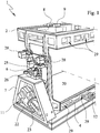
- the FIG. 1 represents a part of a side of a tool carrier 1, which is made in two parts and therefore a tool carrier shell 2 and a detachably connected to the tool carrier shell 2 tool carrier base 4 has.
- the tool carrier upper part 2 serves to receive a tool upper part 3, the lower tool carrier part 4 receiving a tool lower part 5.
- the tool upper part 3 and the lower tool part 3 are not shown for reasons of simplification.
- a tool changer 8 is provided, which is also equipped with an energy interface 9, which serves in this case, the transmission of electrical signals and to provide pneumatic energy.
- the energy interfaces 9-12 for example, provide a vacuum when the tool carrier upper part 2 is transported by a tool robot, which vacuum is required for producing a composite workpiece with a foam layer.
- a signal transmission must take place, which ensures, for example, the transmission of information between the tool carrier upper part 2 and associated vacuum or compressed air valves.
- the mentioned tool changer 8 can be coupled to a tool changer arranged on a robotic arm of a tool robot, so that the entire tool carrier 1 can be picked up and transported with a tooling upper part 2 received therein or only the tool carrier upper part 2 with a tool top 3 arranged therein with the aid of the tool robot.
- the tool robot is also used to separate the tool carrier halves 2, 4 from each other or to connect them together.
- This process allows the placement of a present in the production tool cavity with components, such as the above-mentioned molded skin or a carrier and / or with a reaction mixture which is suitable for foaming.
- the tool carrier upper part 2 can be separated from the tool carrier 1 and lifted off together with a tool upper part 3 received therein. Following this, it is possible to turn off the tool carrier upper part 2, for example laterally next to the tool carrier lower part 4, in order to equip the tool parts 3, 5 with a component.
- the tool carrier upper part 2 is fixed to the tool carrier lower part 4 by means of locking devices 28 when the tool carrier 1 is closed.
- the locking devices 28 in this case have locking pins which engage in corresponding locking bushes 13, which is clearer from the representation in FIG. 6 evident.
- This releasable connection is maintained as long as the tool carrier 1 must remain closed in order to produce a composite workpiece in the production tool.
- Tool holder 1 shown further consists in that it is pivotally mounted in a pivot frame 7, so that it can perform a rotational movement about the axis 6, if necessary.
- the axis 6 is mounted for this purpose in two plain bearing bushings 25 and 26.
- Such a pivoting movement is necessary, for example, in the manufacture of a composite workpiece with a foam layer formed by an intumescent reaction mixture, because this allows an optimal distribution of the forming foam within the composite workpiece can be achieved. Consequently, after the introduction of the reaction mixture into the lower tool part 5 and the closing of the production tool by placing the upper die 3, the entire tool carrier 1 is pivoted about the axis 6 and fixed in this position for a limited time.
- a drive 23 which in the present example is a servo geared motor, which consequently also has a gear 22 for adjusting the rotational movement.
- the tool carrier 1 When looking at the tool carrier 1 is also striking that this is like a truss is executed and therefore has numerous recesses 29, which bring a significant weight saving with it. This leads in the first place that the tool carrier 1 can be transported by means of a tool robot.
- the lower part of the tool 5 receiving side of the tool carrier base 4 is also formed by a clamping plate 20, to the details of which in connection with the description of FIGS. 4 and 7 will be discussed in more detail.
- the tool carrier 1 also has energy interfaces 11 and 12, which allow its storage in a tool magazine.
- This energy interfaces 11, 12 of the tool holder 1 in the tool magazine in the manner described above continues to be supplied with energy, which may for example be a thermal energy to hold the production tool at a defined temperature level, while the foam of the composite workpiece cures.
- energy which may for example be a thermal energy to hold the production tool at a defined temperature level, while the foam of the composite workpiece cures.
- the mentioned energy interfaces 9-12 are each designed as docking stations, so that their assembly and separation are possible without problems and without manual activities.
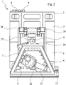
- FIG. 2 From the FIG. 2 goes out a side view of the tool carrier 1 FIG. 1 with a production tool inserted therein, which consists of a tool upper part 3 and a tool lower part 5 connected thereto.
- the upper tool part 3 is in the tool carrier upper part 2 and the lower tool part 5 is received in the lower tool carrier part 4.
- the tool carrier upper part 2 By the locking means 28, the tool carrier upper part 2 is fixed to the tool carrier lower part 4, so that thereby the tool carrier 1 and with this the production tool is closed.
- the side view in FIG. 2 again clearly shows the axis 6, by which the entire production tool including the tool carrier 1 can be pivoted.
- the axis 6 is mounted in the plain bearing bushes 25, 26, which are connected to each other via a screw.
- a drive 23 with a Use gear 22 which corresponds to a space-saving and compact design.
- an energy interface 11 for connecting the tool carrier 1 with a corresponding energy interface of a tool magazine.
- Another, suitable for this energy interface forms the side of the tool holder 1 existing power interface 12th
- the previously described tool changer 8 with an energy interface 9 is arranged on the free outer surface forming the upper side of the tool carrier upper part 2. The tool changer 8 is used for connection to a corresponding tool changer on a robot arm of a tool robot.
- FIG. 3 shows the tool carrier 1 from the FIGS. 1 and 2 in a view from the drive 23 opposite side.
- the swing frame 7, which also has recesses 29 in the course of a lightweight construction, the storage of the tool carrier 1 and its pivoting about the axis 6.
- the arranged on the top of the tool carrier shell 2 tool changer 8 in this case has no energy interface.
- a temperature control unit 24 is used, which is for the maintenance of the production temperature for producing a composite material having a foam layer of importance.
- FIG. 4 From the FIG. 4 is a view from above of the tool carrier 1, but without production tool.
- the clamping plate 20 mounted in the tool carrier lower part 4 is visible, on which the tool lower part 5 is normally fixed.
- the clamping plate 20 is movable in the vertical direction, so that by this movement of the propagating pressure of a foaming reaction mixture of the composite workpiece to be produced can be compensated.
- the Clamping plate 20 floating which means that below the clamping plate 20, an air cushion is created.
- the clamping plate 20 moves sideways she has in the in FIG. 4 illustrated example of two vertical guide elements 21, which are pins in the tool carrier lower part 4, which engage in corresponding holes in the clamping plate 20.
- a tool changer 8 is described with an energy interface 10, which represents the connection piece of a tool robot.
- this is one of the two counterparts to the tool changer 8, which are arranged on the outer surface of the tool carrier upper part 2.
- the in FIG. 5 shown tool changer 8 is fastened with its back to a connecting element 27, which in the present case is a support beam as part of a support structure having a second tool changer on its side, not shown.
- This supporting structure is fixed in its entirety to the tool robot and attached to the free outer surface of the tool carrier upper part 2 for receiving the upper tool part 2 or the tool carrier 1 with the two corresponding tool changers 8.
- the tool changer 8 shown here has the energy interface 10, which has a plurality of vacuum connections 30 in the present case.
- an adapter 31 with a data bus connection 32 is arranged on the tool changer 8, which is for the transmission of electrical or electronic signals is suitable. Consequently, with this adapter 31, the control of the tool carrier 1 or of the production tool received therein can be realized.
- the tool changer 8 in FIG. 5 also has at least one adjusting element 33, which is designed in the present example as a pin which engages in a corresponding recess of the tool changer 8 on the tool carrier upper part 2, when the connection between the tool changer 8 is to be produced.
- FIG. 6 is a detail of a tool shell 3 and a tool lower part 5 shown during the closing operation of the production tool.
- two guide columns 14 are provided, which provide optimum guidance when closing and opening the mold halves 3, 5.
- the guide columns 14 engage in the closing of the tool lower part 5 and the upper die 3 existing production tool in corresponding guide bushings 15 a.
- mutually corresponding energy interfaces are present on the upper tool part 3 and on the lower tool part 4, these engaging directly in one another during the closing of the production tool and establishing a connection.
- the power interfaces are designed in the form of a docking station and have two vacuum ports 34 and three compressed air connections 35.
- the compressed air connections 35 and the vacuum connections 34 are designed as plugs and in the lower tool part 5 as matching beech, which also have a sealing function after merging.
- Another peculiarity of the representation in FIG. 6 consists in that in the upper tool 3 at least two locking bushings 13 are introduced, which are penetrated by the corresponding locking bolt 28 of the locking devices 28 when the production tool is closed.
- FIG. 7 For vertical guidance of the clamping plate in the lower part of the tool carrier 4, the clamping plate 20 has a bore through which the vertical guide element 21, so a bolt becomes. A small part of the bolt protrudes in the example in FIG. 7 out of the clamping plate 20 out.
- a special feature of the solution presented here is that a central connection 16, which has a multiplicity of different connections, is arranged on the tool carrier lower part 4. Here only hinted several compressed air connections 17, vacuum ports 18 and electrical power connections 19 are present.
Landscapes
- Engineering & Computer Science (AREA)
- Mechanical Engineering (AREA)
- Manufacturing & Machinery (AREA)
- Moulds For Moulding Plastics Or The Like (AREA)
Applications Claiming Priority (1)
| Application Number | Priority Date | Filing Date | Title |
|---|---|---|---|
| DE102016120788.8A DE102016120788A1 (de) | 2016-11-01 | 2016-11-01 | Werkzeugträger und Fertigungsanlage mit einem derartigen Werkzeugträger |
Publications (2)
| Publication Number | Publication Date |
|---|---|
| EP3318384A1 true EP3318384A1 (fr) | 2018-05-09 |
| EP3318384B1 EP3318384B1 (fr) | 2021-07-07 |
Family
ID=60117507
Family Applications (1)
| Application Number | Title | Priority Date | Filing Date |
|---|---|---|---|
| EP17196067.7A Active EP3318384B1 (fr) | 2016-11-01 | 2017-10-12 | Porte-outil et installation de fabrication avec un tel porte-outil |
Country Status (2)
| Country | Link |
|---|---|
| EP (1) | EP3318384B1 (fr) |
| DE (1) | DE102016120788A1 (fr) |
Families Citing this family (1)
| Publication number | Priority date | Publication date | Assignee | Title |
|---|---|---|---|---|
| DE102023109958A1 (de) * | 2023-04-20 | 2024-10-24 | Bayerische Motoren Werke Aktiengesellschaft | Werkzeuganordnung |
Citations (8)
| Publication number | Priority date | Publication date | Assignee | Title |
|---|---|---|---|---|
| US4500274A (en) * | 1982-04-26 | 1985-02-19 | Battenfeld Maschinenfabriken Gmbh | Quick-change mold assembly for injection-molding machines |
| US20030077355A1 (en) * | 2001-10-24 | 2003-04-24 | Krauss-Maffei Kunststofftechnik Gmbh | Closing unit for a plastic molding machine |
| JP2006088671A (ja) * | 2004-09-27 | 2006-04-06 | Toyo Tire & Rubber Co Ltd | 発泡成形装置 |
| DE102010002896A1 (de) * | 2010-03-16 | 2011-09-22 | Frimo Group Gmbh | Vorrichtung zur Herstellung eines Schaumformteils in einem Formwerkzeug |
| DE202014106196U1 (de) | 2014-12-19 | 2015-01-26 | Wis Tooling Gmbh | Fertigungsanlage |
| US20150266284A1 (en) * | 2014-03-21 | 2015-09-24 | Ingersoll Machine Tools, Inc. | Flexible fiber placement system for small composite parts manufacturing and methods |
| EP3037237A1 (fr) * | 2014-12-19 | 2016-06-29 | Cannon S.p.A. | Procédé et appareil de moussage d'objets |
| CN105965754A (zh) * | 2016-05-19 | 2016-09-28 | 宁波方正汽车模具有限公司 | 全自动高效发泡模具 |
Family Cites Families (2)
| Publication number | Priority date | Publication date | Assignee | Title |
|---|---|---|---|---|
| DE19646592C2 (de) * | 1996-11-12 | 1998-09-10 | Krauss Maffei Ag | Vorrichtung zum Herstellen von Kunststoffteilen |
| DE102013204801B4 (de) * | 2013-03-19 | 2016-08-18 | Johnson Controls Gmbh | Werkzeugsystem zur Herstellung eines Schaumformteils |
-
2016
- 2016-11-01 DE DE102016120788.8A patent/DE102016120788A1/de not_active Withdrawn
-
2017
- 2017-10-12 EP EP17196067.7A patent/EP3318384B1/fr active Active
Patent Citations (8)
| Publication number | Priority date | Publication date | Assignee | Title |
|---|---|---|---|---|
| US4500274A (en) * | 1982-04-26 | 1985-02-19 | Battenfeld Maschinenfabriken Gmbh | Quick-change mold assembly for injection-molding machines |
| US20030077355A1 (en) * | 2001-10-24 | 2003-04-24 | Krauss-Maffei Kunststofftechnik Gmbh | Closing unit for a plastic molding machine |
| JP2006088671A (ja) * | 2004-09-27 | 2006-04-06 | Toyo Tire & Rubber Co Ltd | 発泡成形装置 |
| DE102010002896A1 (de) * | 2010-03-16 | 2011-09-22 | Frimo Group Gmbh | Vorrichtung zur Herstellung eines Schaumformteils in einem Formwerkzeug |
| US20150266284A1 (en) * | 2014-03-21 | 2015-09-24 | Ingersoll Machine Tools, Inc. | Flexible fiber placement system for small composite parts manufacturing and methods |
| DE202014106196U1 (de) | 2014-12-19 | 2015-01-26 | Wis Tooling Gmbh | Fertigungsanlage |
| EP3037237A1 (fr) * | 2014-12-19 | 2016-06-29 | Cannon S.p.A. | Procédé et appareil de moussage d'objets |
| CN105965754A (zh) * | 2016-05-19 | 2016-09-28 | 宁波方正汽车模具有限公司 | 全自动高效发泡模具 |
Also Published As
| Publication number | Publication date |
|---|---|
| DE102016120788A1 (de) | 2018-05-03 |
| EP3318384B1 (fr) | 2021-07-07 |
Similar Documents
| Publication | Publication Date | Title |
|---|---|---|
| EP3930980B1 (fr) | Apparaie pour moulage par injection un element en matière plastique sur un surface d'un produit semi-fini | |
| EP2030742B1 (fr) | Système de changement d'outil pour un robot industriel | |
| EP3023170B1 (fr) | Dispositif de transfert | |
| EP2694231B1 (fr) | Dispositif de transfert pour une presse ou un train de presses comprenant une transmission et support de base échangeable | |
| EP3315276B1 (fr) | Procédé de fabrication de pièces composites et d'une unité de fabrication pour l'application des méthodes | |
| EP3527325A1 (fr) | Dispositif d'usinage destiné à l'usinage des pièces à usiner | |
| EP2813345B1 (fr) | Procédé de changement d'outil | |
| EP3664959A1 (fr) | Procédé et dispositif de fourniture de vis | |
| EP3318384B1 (fr) | Porte-outil et installation de fabrication avec un tel porte-outil | |
| EP3372369B1 (fr) | Unité de production pour la production de pièces moulées en mousse et d'une unité de fabrication avec au moins une telle unité de production | |
| DE102021000125B4 (de) | Roboter mit einer Abstützeinrichtung | |
| EP3302843B1 (fr) | Outil de pliage pour presse plieuse | |
| DE102013019358A1 (de) | Orientierstation zum Ausrichten eines Werkstücks relativ zu einem Werkzeug, insbesondere einer Presse | |
| EP3302842B1 (fr) | Procédé de réglage d'une section de formage d'un outil de cintrage | |
| EP1563926B1 (fr) | Dispositif et procédé de transport de pièces à usiner | |
| EP1430967A1 (fr) | Dispositif pour manipuler des outils à deux pièces | |
| DE102004052001A1 (de) | Automatische Toolingwechselvorrichtung | |
| DE102009018947B4 (de) | Vorrichtung zur Aufnahme eines Formkerns zum Ablegen von imprägnierten Fasern oder Gewebebändern | |
| DE102016125484B3 (de) | Transfervorrichtung | |
| EP2439046B1 (fr) | Système de fermeture d'outil pour machines de soufflage en matière synthétique | |
| DE102021109686A1 (de) | Mobile Bearbeitungsvorrichtung mit Werkzeugspeicher | |
| EP0951368B1 (fr) | Machine a estamper/cintrer | |
| DE102013220496B4 (de) | Umformmaschine , insbesondere Presse zum Umformen von Werkstücken | |
| DE202004010050U1 (de) | Vorrichtung zum Schäumen, insbesondere zur Verwendung für die Herstellung von Kühlmöbeln | |
| EP2368684A2 (fr) | Dispositif de fermeture |
Legal Events
| Date | Code | Title | Description |
|---|---|---|---|
| PUAI | Public reference made under article 153(3) epc to a published international application that has entered the european phase |
Free format text: ORIGINAL CODE: 0009012 |
|
| STAA | Information on the status of an ep patent application or granted ep patent |
Free format text: STATUS: THE APPLICATION HAS BEEN PUBLISHED |
|
| AK | Designated contracting states |
Kind code of ref document: A1 Designated state(s): AL AT BE BG CH CY CZ DE DK EE ES FI FR GB GR HR HU IE IS IT LI LT LU LV MC MK MT NL NO PL PT RO RS SE SI SK SM TR |
|
| AX | Request for extension of the european patent |
Extension state: BA ME |
|
| STAA | Information on the status of an ep patent application or granted ep patent |
Free format text: STATUS: REQUEST FOR EXAMINATION WAS MADE |
|
| 17P | Request for examination filed |
Effective date: 20181026 |
|
| RBV | Designated contracting states (corrected) |
Designated state(s): AL AT BE BG CH CY CZ DE DK EE ES FI FR GB GR HR HU IE IS IT LI LT LU LV MC MK MT NL NO PL PT RO RS SE SI SK SM TR |
|
| STAA | Information on the status of an ep patent application or granted ep patent |
Free format text: STATUS: EXAMINATION IS IN PROGRESS |
|
| 17Q | First examination report despatched |
Effective date: 20191029 |
|
| GRAP | Despatch of communication of intention to grant a patent |
Free format text: ORIGINAL CODE: EPIDOSNIGR1 |
|
| STAA | Information on the status of an ep patent application or granted ep patent |
Free format text: STATUS: GRANT OF PATENT IS INTENDED |
|
| INTG | Intention to grant announced |
Effective date: 20210309 |
|
| GRAS | Grant fee paid |
Free format text: ORIGINAL CODE: EPIDOSNIGR3 |
|
| GRAA | (expected) grant |
Free format text: ORIGINAL CODE: 0009210 |
|
| STAA | Information on the status of an ep patent application or granted ep patent |
Free format text: STATUS: THE PATENT HAS BEEN GRANTED |
|
| AK | Designated contracting states |
Kind code of ref document: B1 Designated state(s): AL AT BE BG CH CY CZ DE DK EE ES FI FR GB GR HR HU IE IS IT LI LT LU LV MC MK MT NL NO PL PT RO RS SE SI SK SM TR |
|
| REG | Reference to a national code |
Ref country code: GB Ref legal event code: FG4D Free format text: NOT ENGLISH |
|
| REG | Reference to a national code |
Ref country code: AT Ref legal event code: REF Ref document number: 1408119 Country of ref document: AT Kind code of ref document: T Effective date: 20210715 |
|
| REG | Reference to a national code |
Ref country code: DE Ref legal event code: R096 Ref document number: 502017010833 Country of ref document: DE |
|
| REG | Reference to a national code |
Ref country code: IE Ref legal event code: FG4D Free format text: LANGUAGE OF EP DOCUMENT: GERMAN |
|
| REG | Reference to a national code |
Ref country code: LT Ref legal event code: MG9D |
|
| REG | Reference to a national code |
Ref country code: NL Ref legal event code: MP Effective date: 20210707 |
|
| PG25 | Lapsed in a contracting state [announced via postgrant information from national office to epo] |
Ref country code: RS Free format text: LAPSE BECAUSE OF FAILURE TO SUBMIT A TRANSLATION OF THE DESCRIPTION OR TO PAY THE FEE WITHIN THE PRESCRIBED TIME-LIMIT Effective date: 20210707 Ref country code: SE Free format text: LAPSE BECAUSE OF FAILURE TO SUBMIT A TRANSLATION OF THE DESCRIPTION OR TO PAY THE FEE WITHIN THE PRESCRIBED TIME-LIMIT Effective date: 20210707 Ref country code: HR Free format text: LAPSE BECAUSE OF FAILURE TO SUBMIT A TRANSLATION OF THE DESCRIPTION OR TO PAY THE FEE WITHIN THE PRESCRIBED TIME-LIMIT Effective date: 20210707 Ref country code: LT Free format text: LAPSE BECAUSE OF FAILURE TO SUBMIT A TRANSLATION OF THE DESCRIPTION OR TO PAY THE FEE WITHIN THE PRESCRIBED TIME-LIMIT Effective date: 20210707 Ref country code: BG Free format text: LAPSE BECAUSE OF FAILURE TO SUBMIT A TRANSLATION OF THE DESCRIPTION OR TO PAY THE FEE WITHIN THE PRESCRIBED TIME-LIMIT Effective date: 20211007 Ref country code: NL Free format text: LAPSE BECAUSE OF FAILURE TO SUBMIT A TRANSLATION OF THE DESCRIPTION OR TO PAY THE FEE WITHIN THE PRESCRIBED TIME-LIMIT Effective date: 20210707 Ref country code: NO Free format text: LAPSE BECAUSE OF FAILURE TO SUBMIT A TRANSLATION OF THE DESCRIPTION OR TO PAY THE FEE WITHIN THE PRESCRIBED TIME-LIMIT Effective date: 20211007 Ref country code: PT Free format text: LAPSE BECAUSE OF FAILURE TO SUBMIT A TRANSLATION OF THE DESCRIPTION OR TO PAY THE FEE WITHIN THE PRESCRIBED TIME-LIMIT Effective date: 20211108 Ref country code: ES Free format text: LAPSE BECAUSE OF FAILURE TO SUBMIT A TRANSLATION OF THE DESCRIPTION OR TO PAY THE FEE WITHIN THE PRESCRIBED TIME-LIMIT Effective date: 20210707 Ref country code: FI Free format text: LAPSE BECAUSE OF FAILURE TO SUBMIT A TRANSLATION OF THE DESCRIPTION OR TO PAY THE FEE WITHIN THE PRESCRIBED TIME-LIMIT Effective date: 20210707 |
|
| PG25 | Lapsed in a contracting state [announced via postgrant information from national office to epo] |
Ref country code: PL Free format text: LAPSE BECAUSE OF FAILURE TO SUBMIT A TRANSLATION OF THE DESCRIPTION OR TO PAY THE FEE WITHIN THE PRESCRIBED TIME-LIMIT Effective date: 20210707 Ref country code: LV Free format text: LAPSE BECAUSE OF FAILURE TO SUBMIT A TRANSLATION OF THE DESCRIPTION OR TO PAY THE FEE WITHIN THE PRESCRIBED TIME-LIMIT Effective date: 20210707 Ref country code: GR Free format text: LAPSE BECAUSE OF FAILURE TO SUBMIT A TRANSLATION OF THE DESCRIPTION OR TO PAY THE FEE WITHIN THE PRESCRIBED TIME-LIMIT Effective date: 20211008 |
|
| REG | Reference to a national code |
Ref country code: DE Ref legal event code: R097 Ref document number: 502017010833 Country of ref document: DE |
|
| PG25 | Lapsed in a contracting state [announced via postgrant information from national office to epo] |
Ref country code: DK Free format text: LAPSE BECAUSE OF FAILURE TO SUBMIT A TRANSLATION OF THE DESCRIPTION OR TO PAY THE FEE WITHIN THE PRESCRIBED TIME-LIMIT Effective date: 20210707 |
|
| PLBE | No opposition filed within time limit |
Free format text: ORIGINAL CODE: 0009261 |
|
| STAA | Information on the status of an ep patent application or granted ep patent |
Free format text: STATUS: NO OPPOSITION FILED WITHIN TIME LIMIT |
|
| REG | Reference to a national code |
Ref country code: CH Ref legal event code: PL |
|
| PG25 | Lapsed in a contracting state [announced via postgrant information from national office to epo] |
Ref country code: SM Free format text: LAPSE BECAUSE OF FAILURE TO SUBMIT A TRANSLATION OF THE DESCRIPTION OR TO PAY THE FEE WITHIN THE PRESCRIBED TIME-LIMIT Effective date: 20210707 Ref country code: SK Free format text: LAPSE BECAUSE OF FAILURE TO SUBMIT A TRANSLATION OF THE DESCRIPTION OR TO PAY THE FEE WITHIN THE PRESCRIBED TIME-LIMIT Effective date: 20210707 Ref country code: RO Free format text: LAPSE BECAUSE OF FAILURE TO SUBMIT A TRANSLATION OF THE DESCRIPTION OR TO PAY THE FEE WITHIN THE PRESCRIBED TIME-LIMIT Effective date: 20210707 Ref country code: EE Free format text: LAPSE BECAUSE OF FAILURE TO SUBMIT A TRANSLATION OF THE DESCRIPTION OR TO PAY THE FEE WITHIN THE PRESCRIBED TIME-LIMIT Effective date: 20210707 Ref country code: CZ Free format text: LAPSE BECAUSE OF FAILURE TO SUBMIT A TRANSLATION OF THE DESCRIPTION OR TO PAY THE FEE WITHIN THE PRESCRIBED TIME-LIMIT Effective date: 20210707 Ref country code: AL Free format text: LAPSE BECAUSE OF FAILURE TO SUBMIT A TRANSLATION OF THE DESCRIPTION OR TO PAY THE FEE WITHIN THE PRESCRIBED TIME-LIMIT Effective date: 20210707 |
|
| 26N | No opposition filed |
Effective date: 20220408 |
|
| REG | Reference to a national code |
Ref country code: BE Ref legal event code: MM Effective date: 20211031 |
|
| GBPC | Gb: european patent ceased through non-payment of renewal fee |
Effective date: 20211012 |
|
| PG25 | Lapsed in a contracting state [announced via postgrant information from national office to epo] |
Ref country code: MC Free format text: LAPSE BECAUSE OF FAILURE TO SUBMIT A TRANSLATION OF THE DESCRIPTION OR TO PAY THE FEE WITHIN THE PRESCRIBED TIME-LIMIT Effective date: 20210707 |
|
| PG25 | Lapsed in a contracting state [announced via postgrant information from national office to epo] |
Ref country code: LU Free format text: LAPSE BECAUSE OF NON-PAYMENT OF DUE FEES Effective date: 20211012 Ref country code: IT Free format text: LAPSE BECAUSE OF FAILURE TO SUBMIT A TRANSLATION OF THE DESCRIPTION OR TO PAY THE FEE WITHIN THE PRESCRIBED TIME-LIMIT Effective date: 20210707 Ref country code: GB Free format text: LAPSE BECAUSE OF NON-PAYMENT OF DUE FEES Effective date: 20211012 Ref country code: BE Free format text: LAPSE BECAUSE OF NON-PAYMENT OF DUE FEES Effective date: 20211031 |
|
| PG25 | Lapsed in a contracting state [announced via postgrant information from national office to epo] |
Ref country code: LI Free format text: LAPSE BECAUSE OF NON-PAYMENT OF DUE FEES Effective date: 20211031 Ref country code: CH Free format text: LAPSE BECAUSE OF NON-PAYMENT OF DUE FEES Effective date: 20211031 |
|
| PG25 | Lapsed in a contracting state [announced via postgrant information from national office to epo] |
Ref country code: FR Free format text: LAPSE BECAUSE OF NON-PAYMENT OF DUE FEES Effective date: 20211031 |
|
| PG25 | Lapsed in a contracting state [announced via postgrant information from national office to epo] |
Ref country code: IE Free format text: LAPSE BECAUSE OF NON-PAYMENT OF DUE FEES Effective date: 20211012 |
|
| PG25 | Lapsed in a contracting state [announced via postgrant information from national office to epo] |
Ref country code: HU Free format text: LAPSE BECAUSE OF FAILURE TO SUBMIT A TRANSLATION OF THE DESCRIPTION OR TO PAY THE FEE WITHIN THE PRESCRIBED TIME-LIMIT; INVALID AB INITIO Effective date: 20171012 |
|
| P01 | Opt-out of the competence of the unified patent court (upc) registered |
Effective date: 20230412 |
|
| P02 | Opt-out of the competence of the unified patent court (upc) changed |
Effective date: 20230515 |
|
| PG25 | Lapsed in a contracting state [announced via postgrant information from national office to epo] |
Ref country code: CY Free format text: LAPSE BECAUSE OF FAILURE TO SUBMIT A TRANSLATION OF THE DESCRIPTION OR TO PAY THE FEE WITHIN THE PRESCRIBED TIME-LIMIT Effective date: 20210707 |
|
| REG | Reference to a national code |
Ref country code: AT Ref legal event code: MM01 Ref document number: 1408119 Country of ref document: AT Kind code of ref document: T Effective date: 20221012 |
|
| PG25 | Lapsed in a contracting state [announced via postgrant information from national office to epo] |
Ref country code: AT Free format text: LAPSE BECAUSE OF NON-PAYMENT OF DUE FEES Effective date: 20221012 |
|
| PG25 | Lapsed in a contracting state [announced via postgrant information from national office to epo] |
Ref country code: MK Free format text: LAPSE BECAUSE OF FAILURE TO SUBMIT A TRANSLATION OF THE DESCRIPTION OR TO PAY THE FEE WITHIN THE PRESCRIBED TIME-LIMIT Effective date: 20210707 |
|
| PG25 | Lapsed in a contracting state [announced via postgrant information from national office to epo] |
Ref country code: TR Free format text: LAPSE BECAUSE OF FAILURE TO SUBMIT A TRANSLATION OF THE DESCRIPTION OR TO PAY THE FEE WITHIN THE PRESCRIBED TIME-LIMIT Effective date: 20210707 |
|
| PG25 | Lapsed in a contracting state [announced via postgrant information from national office to epo] |
Ref country code: MT Free format text: LAPSE BECAUSE OF FAILURE TO SUBMIT A TRANSLATION OF THE DESCRIPTION OR TO PAY THE FEE WITHIN THE PRESCRIBED TIME-LIMIT Effective date: 20210707 |
|
| REG | Reference to a national code |
Ref country code: DE Ref legal event code: R081 Ref document number: 502017010833 Country of ref document: DE Owner name: JOSEF WEISCHER GMBH, DE Free format text: FORMER OWNER: JOSEF WEISCHER GMBH & CO. KG, 48282 EMSDETTEN, DE |
|
| PGFP | Annual fee paid to national office [announced via postgrant information from national office to epo] |
Ref country code: DE Payment date: 20250926 Year of fee payment: 9 |