EP3318453A1 - Fremdstoffbeseitigungsvorrichtung und damit ausgestattetes fahrzeug - Google Patents
Fremdstoffbeseitigungsvorrichtung und damit ausgestattetes fahrzeug Download PDFInfo
- Publication number
- EP3318453A1 EP3318453A1 EP16817796.2A EP16817796A EP3318453A1 EP 3318453 A1 EP3318453 A1 EP 3318453A1 EP 16817796 A EP16817796 A EP 16817796A EP 3318453 A1 EP3318453 A1 EP 3318453A1
- Authority
- EP
- European Patent Office
- Prior art keywords
- generation unit
- foreign matter
- removal device
- pressure air
- matter removal
- Prior art date
- Legal status (The legal status is an assumption and is not a legal conclusion. Google has not performed a legal analysis and makes no representation as to the accuracy of the status listed.)
- Granted
Links
Images





Classifications
-
- B—PERFORMING OPERATIONS; TRANSPORTING
- B60—VEHICLES IN GENERAL
- B60S—SERVICING, CLEANING, REPAIRING, SUPPORTING, LIFTING, OR MANOEUVRING OF VEHICLES, NOT OTHERWISE PROVIDED FOR
- B60S1/00—Cleaning of vehicles
- B60S1/62—Other vehicle fittings for cleaning
-
- B—PERFORMING OPERATIONS; TRANSPORTING
- B05—SPRAYING OR ATOMISING IN GENERAL; APPLYING FLUENT MATERIALS TO SURFACES, IN GENERAL
- B05B—SPRAYING APPARATUS; ATOMISING APPARATUS; NOZZLES
- B05B9/00—Spraying apparatus for discharge of liquids or other fluent material, without essentially mixing with gas or vapour
- B05B9/03—Spraying apparatus for discharge of liquids or other fluent material, without essentially mixing with gas or vapour characterised by means for supplying liquid or other fluent material
- B05B9/04—Spraying apparatus for discharge of liquids or other fluent material, without essentially mixing with gas or vapour characterised by means for supplying liquid or other fluent material with pressurised or compressible container; with pump
- B05B9/0403—Spraying apparatus for discharge of liquids or other fluent material, without essentially mixing with gas or vapour characterised by means for supplying liquid or other fluent material with pressurised or compressible container; with pump with pumps for liquids or other fluent material
- B05B9/0413—Spraying apparatus for discharge of liquids or other fluent material, without essentially mixing with gas or vapour characterised by means for supplying liquid or other fluent material with pressurised or compressible container; with pump with pumps for liquids or other fluent material with reciprocating pumps, e.g. membrane pump, piston pump, bellow pump
-
- B—PERFORMING OPERATIONS; TRANSPORTING
- B60—VEHICLES IN GENERAL
- B60R—VEHICLES, VEHICLE FITTINGS, OR VEHICLE PARTS, NOT OTHERWISE PROVIDED FOR
- B60R11/00—Arrangements for holding or mounting articles, not otherwise provided for
- B60R11/04—Mounting of cameras operative during drive; Arrangement of controls thereof relative to the vehicle
-
- B—PERFORMING OPERATIONS; TRANSPORTING
- B60—VEHICLES IN GENERAL
- B60S—SERVICING, CLEANING, REPAIRING, SUPPORTING, LIFTING, OR MANOEUVRING OF VEHICLES, NOT OTHERWISE PROVIDED FOR
- B60S1/00—Cleaning of vehicles
- B60S1/02—Cleaning windscreens, windows or optical devices
- B60S1/56—Cleaning windscreens, windows or optical devices specially adapted for cleaning other parts or devices than front windows or windscreens
-
- F—MECHANICAL ENGINEERING; LIGHTING; HEATING; WEAPONS; BLASTING
- F04—POSITIVE - DISPLACEMENT MACHINES FOR LIQUIDS; PUMPS FOR LIQUIDS OR ELASTIC FLUIDS
- F04B—POSITIVE-DISPLACEMENT MACHINES FOR LIQUIDS; PUMPS
- F04B35/00—Piston pumps specially adapted for elastic fluids and characterised by the driving means to their working members, or by combination with, or adaptation to, specific driving engines or motors, not otherwise provided for
- F04B35/01—Piston pumps specially adapted for elastic fluids and characterised by the driving means to their working members, or by combination with, or adaptation to, specific driving engines or motors, not otherwise provided for the means being mechanical
-
- F—MECHANICAL ENGINEERING; LIGHTING; HEATING; WEAPONS; BLASTING
- F16—ENGINEERING ELEMENTS AND UNITS; GENERAL MEASURES FOR PRODUCING AND MAINTAINING EFFECTIVE FUNCTIONING OF MACHINES OR INSTALLATIONS; THERMAL INSULATION IN GENERAL
- F16F—SPRINGS; SHOCK-ABSORBERS; MEANS FOR DAMPING VIBRATION
- F16F1/00—Springs
- F16F1/36—Springs made of rubber or other material having high internal friction, e.g. thermoplastic elastomers
- F16F1/373—Springs made of rubber or other material having high internal friction, e.g. thermoplastic elastomers characterised by having a particular shape
- F16F1/3732—Springs made of rubber or other material having high internal friction, e.g. thermoplastic elastomers characterised by having a particular shape having an annular or the like shape, e.g. grommet-type resilient mountings
-
- F—MECHANICAL ENGINEERING; LIGHTING; HEATING; WEAPONS; BLASTING
- F16—ENGINEERING ELEMENTS AND UNITS; GENERAL MEASURES FOR PRODUCING AND MAINTAINING EFFECTIVE FUNCTIONING OF MACHINES OR INSTALLATIONS; THERMAL INSULATION IN GENERAL
- F16F—SPRINGS; SHOCK-ABSORBERS; MEANS FOR DAMPING VIBRATION
- F16F15/00—Suppression of vibrations in systems; Means or arrangements for avoiding or reducing out-of-balance forces, e.g. due to motion
- F16F15/02—Suppression of vibrations of non-rotating, e.g. reciprocating systems; Suppression of vibrations of rotating systems by use of members not moving with the rotating systems
- F16F15/04—Suppression of vibrations of non-rotating, e.g. reciprocating systems; Suppression of vibrations of rotating systems by use of members not moving with the rotating systems using elastic means
- F16F15/08—Suppression of vibrations of non-rotating, e.g. reciprocating systems; Suppression of vibrations of rotating systems by use of members not moving with the rotating systems using elastic means with rubber springs ; with springs made of rubber and metal
-
- H—ELECTRICITY
- H04—ELECTRIC COMMUNICATION TECHNIQUE
- H04N—PICTORIAL COMMUNICATION, e.g. TELEVISION
- H04N23/00—Cameras or camera modules comprising electronic image sensors; Control thereof
- H04N23/80—Camera processing pipelines; Components thereof
- H04N23/81—Camera processing pipelines; Components thereof for suppressing or minimising disturbance in the image signal generation
- H04N23/811—Camera processing pipelines; Components thereof for suppressing or minimising disturbance in the image signal generation by dust removal, e.g. from surfaces of the image sensor or processing of the image signal output by the electronic image sensor
-
- H—ELECTRICITY
- H04—ELECTRIC COMMUNICATION TECHNIQUE
- H04N—PICTORIAL COMMUNICATION, e.g. TELEVISION
- H04N7/00—Television systems
- H04N7/18—Closed-circuit television [CCTV] systems, i.e. systems in which the video signal is not broadcast
-
- B—PERFORMING OPERATIONS; TRANSPORTING
- B60—VEHICLES IN GENERAL
- B60R—VEHICLES, VEHICLE FITTINGS, OR VEHICLE PARTS, NOT OTHERWISE PROVIDED FOR
- B60R11/00—Arrangements for holding or mounting articles, not otherwise provided for
- B60R2011/0001—Arrangements for holding or mounting articles, not otherwise provided for characterised by position
- B60R2011/004—Arrangements for holding or mounting articles, not otherwise provided for characterised by position outside the vehicle
-
- B—PERFORMING OPERATIONS; TRANSPORTING
- B60—VEHICLES IN GENERAL
- B60S—SERVICING, CLEANING, REPAIRING, SUPPORTING, LIFTING, OR MANOEUVRING OF VEHICLES, NOT OTHERWISE PROVIDED FOR
- B60S1/00—Cleaning of vehicles
- B60S1/02—Cleaning windscreens, windows or optical devices
- B60S1/54—Cleaning windscreens, windows or optical devices using gas, e.g. hot air
Definitions
- the present invention relates to a device for removing foreign matters by injecting high-pressure air.
- Patent Document 1 Japanese Patent Laid-Open Publication No. 2001-171491
- high-pressure air generated by a high-pressure air generation unit (referred to as "high-pressure air generating unit in Patent Document 1) is injected toward a lens to blow away foreign matters such as mud and water droplets.
- the high-pressure air generation unit for generating the high-pressure air is installed at any place of a vehicle.
- Patent Document 1 does not specifically disclose a configuration for attaching the high-pressure air generation unit.
- the present inventors have tried a configuration in which a high-pressure air generation unit is attached on a panel constituting a back door or the like of a vehicle, for example.
- a high-pressure air generation unit is attached on a panel constituting a back door or the like of a vehicle, for example.
- the shape of the panel of the vehicle varies depending on the type of the vehicle. Therefore, it has been found that an area for mounting the high-pressure air generation unit on the panel may not be secured and the versatility at the time of attaching the high-pressure air generation unit on the vehicle is lowered.
- One object of the present invention is to provide a foreign matter removal device capable of enhancing the versatility at the time of attaching the high-pressure air generation unit, and a vehicle provided with the foreign matter removal device.
- the present inventors have found that the sound and vibration due to the operation of a drive source such as a motor mounted inside a housing of a high-pressure air generation unit may become abnormal noise by being resonated by a panel.
- Another object of the present invention is to provide a foreign matter removal device capable of suppressing the occurrence of abnormal noise due to the operation of the drive source of the high-pressure air generation unit, and a vehicle provided with the foreign matter removal device.
- a foreign matter removal device of the present invention removes foreign matters on a lens of an in-vehicle camera attached to a vehicle so that the lens of the in-vehicle camera is exposed toward the outside of a body panel of a vehicle, the foreign matter removal device comprising:
- the housing of the high-pressure air generation unit is attached to the panel member constituting the vehicle via the plate-shaped adhesive member having the elastically deformable adhesion layer.
- the adhesion layer of the adhesive member is elastically deformable along the surface shape of the panel member of the vehicle. Even when the panel member has a curved portion or an uneven portion, the adhesion layer is deformed along the curved portion or the uneven portion and makes surface contact therewith. Therefore, a contact area for obtaining an adhesive force required for fixing the housing on the panel member can be secured, so that the versatility at the time of attaching the high-pressure air generation unit can be improved.
- the adhesive member may have an adhesive surface portion on which the adhesion layer is formed, and a mounting portion which is formed continuously with the adhesive surface portion and on which the housing can be mounted, and a gap may be formed between the adhesive surface portion and the housing in a state in which the housing is mounted on the mounting portion.
- the gap is formed between the adhesive surface portion and the housing, the deformation of the adhesion layer is less susceptible to the influence of the rigidity of the housing of the high-pressure air generation unit. Therefore, the adhesion surface portion is likely to be deformed along the curved portion or the uneven portion of the panel member, so that the versatility at the time of attaching the high-pressure air generation unit can be further improved.
- the adhesive surface portion may include at least three plate-shaped members separated from each other, and the plate-shaped members may be connected to each other via the mounting portion.
- the adhesive surface portion includes three separated members, the adhesion surface portion is more easily deformed with respect to the curved portion or the uneven portion of the panel member and is likely to make contact therewith. In this way, the versatility during attachment is further improved.
- the mounting portion may have a connecting portion that connects the housing and the mounting portion, and the connecting portion may be configured to be elastically deformable.
- the connecting portion can function as a cushioning member, the sound and vibration due to the operation of the drive source are difficult to propagate to the panel member. Therefore, it is possible to suppress the occurrence of abnormal noise due to the operation of the drive source.
- the adhesive member may have an adhesive surface portion on which the adhesion layer is at least partially formed, and a connecting member that connects the adhesive surface portion and the housing, and a gap may be formed between the adhesive surface portion and the housing in a state in which the housing is fixed by the connecting member.
- the gap is formed between the adhesive surface portion and the housing, the deformation of the adhesion layer is less susceptible to the influence of the rigidity of the housing of the high-pressure air generation unit. Therefore, the adhesion surface portion is likely to be deformed along the curved portion or the uneven portion of the panel member, so that the versatility at the time of attaching the high-pressure air generation unit can be further improved.
- the connecting member may be formed of an elastic material.
- the connecting member can function as a cushioning member, the sound and vibration due to the operation of the drive source are difficult to propagate to the panel member. Therefore, it is possible to suppress the occurrence of abnormal noise due to the operation of the drive source.
- the adhesive surface portion may have a flange portion that can be bent and deformed.
- the in-vehicle camera and the high-pressure air generation unit may be attached to the panel member.
- the pipeline length of a hose or the like for delivering the high-pressure air generated by the high-pressure air generation unit can be shortened, and the versatility at the time of attaching the high-pressure air generation unit can be further improved, as compared with a configuration in which the in-vehicle camera and the high-pressure air generation unit are attached to different members.
- the panel member may be a back door panel constituting an outer surface of a back door of the vehicle
- the in-vehicle camera may be attached to the back door panel
- the high-pressure air generation unit may be disposed at a position closer to a hinge mechanism of the back door panel than the in-vehicle camera.
- an impact force applied to the high-pressure air generation unit at the time of opening and closing the back door is small and a contact area for obtaining an adhesive force required for fixing the housing on the panel member can be reduced, as compared with a configuration in which the high-pressure air generation unit is disposed at a position farther from the hinge mechanism of the back door panel than the in-vehicle camera. Therefore, it is possible to further improve the versatility at the time of attaching the high-pressure air generation unit.
- the housing may have a first surface facing the panel member and a second surface on which a connector part that supplies power to the drive source is formed, and the second surface may be provided as a surface different from the first surface.
- the second surface on which the connector part is formed does not face the panel member of the vehicle, it is easy to attach the housing of the high-pressure air generation unit to the panel member of the vehicle and it is also easy to secure a wiring for power supply. In this way, the versatility at the time of attaching the high-pressure air generation unit can be further improved.
- the generation unit may have a piston and an elastic member, and the generation unit may generate the high-pressure air by storing an elastic force of the elastic member by using the drive source and releasing the elastic force to move the piston at a high speed.
- the high-pressure air generation unit can be reduced in size and weight, so that the versatility at the time of attaching the high-pressure air generation unit is further improved.
- the foreign matter removal device of the present invention may continuously generate the high-pressure air by repeatedly moving the piston at a high speed by using the drive source and the elastic member.
- a movement direction of the piston when generating the high-pressure air may be parallel to the surface where the adhesive member makes surface contact with the panel member.
- a foreign matter removal device of the present invention removes foreign matters on a lens, the foreign matter removal device comprising:
- the housing of the high-pressure air generation unit is attached to the panel member via the plate-shaped adhesive member having the elastically deformable adhesion layer.
- the adhesion layer of the adhesive member is elastically deformable along the surface shape of the panel member. Even when the panel member has a curved portion or an uneven portion, the adhesion layer is deformed along the curved portion or the uneven portion and makes surface contact therewith. Therefore, a contact area for obtaining an adhesive force required for fixing the housing on the panel member can be secured, so that the versatility at the time of attaching the high-pressure air generation unit can be improved.
- a vehicle of the present invention comprises the foreign matter removal device described above.
- a foreign matter removal device of the present invention removes foreign matters on a lens of an in-vehicle camera attached to a vehicle so that the lens of the in-vehicle camera is exposed toward the outside of a body panel of a vehicle, the foreign matter removal device comprising:
- the high-pressure air generation unit is attached to the panel member of the vehicle by the connecting member and the fixing member in a state in which the gap is formed between the panel member and the high-pressure air generation unit. Therefore, the sound and vibration due to the operation of the drive source of the high-pressure air generation unit are reduced by the connecting member capable of absorbing the vibration and are difficult to propagate to the panel member of the vehicle. In this way, according to the above configuration, the sound and vibration due to the operation of the drive source of the high-pressure air generation unit are prevented from being resonated by the panel member, and hence, the occurrence of abnormal noise can be suppressed.
- the fixing member may be fixed to the panel member via an adhesive member having an elastically deformable adhesion layer.
- the plate-shaped adhesive member including the elastically deformable adhesion layer can also function as a cushioning member. Therefore, according to the above configuration, the sound and vibration due to the operation of the drive source can be also buffered by the adhesive member, so that the sound and vibration are further difficult to propagate to the panel member. In this way, the occurrence of abnormal noise due to the operation of the drive source is further suppressed.
- the connecting member may include a plurality of elastic members.
- each of the elastic members can disperse and reduce the sound and vibration due to the operation of the drive source. Further, even when an impact is applied to the housing of the high-pressure air generation unit due to, for example, an external factor such as when opening and closing the back door, each of the elastic members can disperse and reduce the impact.
- the fixing member may have a flange portion that can be bent and deformed.
- the fixing member and the connecting member may be integrally formed of the same material.
- the fixing member may include a plurality of plate-shaped members separated from each other, and the plate-shaped members may be connected to each other via the connecting member.
- each of the plate-shaped members can disperse and reduce the impact.
- the panel member may be a back door panel constituting an outer surface of a back door of the vehicle
- the in-vehicle camera may be attached to the back door panel
- the high-pressure air generation unit may be disposed at a position closer to a hinge mechanism of the back door panel than the in-vehicle camera.
- an impact force applied to the high-pressure air generation unit at the time of opening and closing the back door can be suppressed to a low level, as compared with a configuration in which the high-pressure air generation unit is disposed at a position farther from the hinge mechanism of the back door panel than the in-vehicle camera.
- the generation unit may have a piston and an elastic member, and the generation unit may generate the high-pressure air by storing an elastic force of the elastic member by using the drive source and releasing the elastic force to move the piston at a high speed.
- the high-pressure air generation unit can be reduced in size and weight, and the sound and vibration due to the operation of the drive source can be reduced.
- the generation unit may continuously generate the high-pressure air by repeatedly moving the piston at a high speed by using the drive source and the elastic member.
- a movement direction of the piston when generating the high-pressure air may be parallel to the surface where the fixing member makes surface contact with the panel member.
- a foreign matter removal device of the present invention removes foreign matters on a lens, the foreign matter removal device comprising:
- the high-pressure air generation unit is attached to the panel member by the connecting member and the fixing member in a state in which the gap is formed between the panel member and the high-pressure air generation unit. Therefore, the sound and vibration due to the operation of the drive source of the high-pressure air generation unit are reduced by the connecting member capable of absorbing the vibration and are difficult to propagate to the panel member. In this way, according to the above configuration, the sound and vibration due to the operation of the drive source of the high-pressure air generation unit are prevented from being resonated by the panel member, and hence, the occurrence of abnormal noise can be suppressed.
- a vehicle of the present invention comprises the foreign matter removal device described above.
- the foreign matter removal device and the vehicle equipped with the foreign matter removal device of the present invention it is possible to improve the versatility at the time of attaching the high-pressure air generation unit.
- the foreign matter removal device and the vehicle equipped with the foreign matter removal device of the present invention it is possible to suppress the occurrence of abnormal noise due to the operation of the drive source of the high-pressure air generation unit.
- a foreign matter removal device of the present invention is applied as a device for removing foreign matters such as water droplets, mud and dust adhering to a lens of an in-vehicle camera.
- a foreign matter removal device 1 is attached to a back door 200A of a vehicle V, for example.
- the foreign matter removal device 1 is provided with a motor 55, and a power supply terminal of the motor 55 is connected to a power supply line of a vehicle.
- a vehicle control unit ECU; not shown
- ECU vehicle control unit
- the foreign matter removal device 1 is controlled to operate by the vehicle control unit (ECU) within several seconds at the start of photographing, for example.
- the in-vehicle camera 100 is a camera for confirming, for example, the rear side of the vehicle V and, as shown in FIG. 1C , a lens 101 of the in-vehicle camera 100 is attached to the back door 200A so that it is exposed toward the outside of the back door 200A of the vehicle V.
- the in-vehicle camera 100 is provided with an imaging unit (not shown), and the lens 101 covers the imaging unit.
- an imaging unit not shown
- the lens 101 covers the imaging unit.
- a simple translucent cover that does not converge or diffuse light is also included in the lens of this example.
- the foreign matter removal device 1 may be attached to a rear bumper 200B of the vehicle V, for example.
- the position at which the in-vehicle camera 100 is attached is not limited to the rear end side of the vehicle but may be a body panel such as the front side or lateral side of the vehicle.
- the meaning of the phrase, "to be attached to the body panel,” includes, for example, a case where the in-vehicle camera is attached via a vehicle mounted component such as a lamp, a door knob, a mirror, a bumper attached to the body panel and a case where the in-vehicle camera is mounted as a part (as an integral body) of these components.
- the foreign matter removal device 1 includes a nozzle unit 2, a joint member 3, a hose 4, and a high-pressure air generation unit 5.
- the nozzle unit 2 is configured to be removably attached to the in-vehicle camera 100.
- the nozzle unit 2 includes an attachment part 21 and a nozzle 22.
- the nozzle unit 2 is formed of resin material, for example.
- the attachment part 21 is attached to a housing 102 of the in-vehicle camera 100 so as to cover a top surface of the in-vehicle camera 100.
- the nozzle 22 injects high-pressure air toward a lens 101 of the in-vehicle camera 100.
- the nozzle 22 is formed integrally with the attachment part 21.
- the nozzle 22 is provided in such a way that a tip end of the nozzle 22 faces the lens 101 when the attachment part 21 is attached to the housing 102.
- the phrase, "formed integrally with,” means that an operator can handle the nozzle 22 and the attachment part 21 as an integral part during assembly work.
- the nozzle 22 and the attachment part 21 may be molded of the same material and in the same mold.
- the nozzle 22 and the attachment part 21 may be respectively molded of separate materials, and then, fitted together and formed integrally, thereby constituting the nozzle unit 2.
- the joint member 3 is a member for joining the nozzle 22 of the nozzle unit 2 and the hose 4. One end portion of the joint member 3 is connected to the nozzle 22 and the opposite end portion thereof is connected to the hose 4.
- the joint member 3 is formed of resin material, for example.
- the hose 4 is a piping member that connects, together with the joint member 3, the nozzle 22 and a high-pressure air generation unit 5. One end portion of the hose 4 is connected to the joint member 3 and the opposite end portion thereof is connected to a discharge port 50 of the high-pressure air generation unit 5.
- the hose 4 is formed of, for example, a material such as resin or rubber.
- the high-pressure air generation unit 5 is a unit for generating high-pressure air to be fed to the nozzle 22,
- the high-pressure air generation unit 5 is attached to a part of a vehicle body at the inside of a vehicle.
- the high-pressure air generation unit 5 includes a housing (case main body) 51 and a moving mechanism (generation unit) 65 disposed inside the housing 51.
- the moving mechanism 65 generates high-pressure air.
- a moving direction of a piston 52 in the high-pressure air generation unit 5 a rearward direction that is a direction of feeding out air refers to a feeding direction, and a forward direction that is opposite to the feeding direction refers to a force accumulation direction.
- the piston 52 In an initial state before high-pressure air is fed out, the piston 52 is positioned on the feeding direction side, and a rack 53 is positioned in a state where a rack portion 53a is engageable with a gear portion 54a of a pinion 54.
- the in-vehicle camera 100 and the high-pressure air generation unit 5 are fixed to a back door panel (an example of the panel member) 200a constituting an outer surface of the back door 200A of the vehicle V, for example.
- the in-vehicle camera 100 is disposed outside the back door 200A, and the high-pressure air generation unit 5 is disposed inside an outer panel of the back door 200A.
- the high-pressure air generation unit 5 is disposed at a position closer to a hinge mechanism 201 of the back door 200A than the in-vehicle camera 100.
- FIG 6A is an enlarged view of the high-pressure air generation unit 5 shown in FIG. 5 .
- FIG. 6B is a plan view showing the high-pressure air generation unit 5 mounted on an adhesive member 71.
- FIGS. 7A and 7B show a top perspective view and a bottom perspective view of FIG. 6B , respectively.
- FIGS. 8A and 8B are views in which the high-pressure air generation unit 5 in FIGS. 7A and 7B is removed, showing a perspective view of the adhesive member 71 as seen from above and a perspective view thereof as seen from below, respectively.
- the adhesive member 71 has an adhesion surface portion 71A, an adhesion layer 71B, and a mounting portion 71C.
- the adhesion surface portion 71A is constituted by a plurality of (three in this example) plate-shaped members separated from each other.
- the adhesion layer 71B is formed on the surface of each adhesion surface portion 71A on the side facing the back door panel 200a.
- the adhesion layer 71B is formed of, for example, a double-sided tape having a predetermined thickness.
- the adhesion layer 71B is configured so as to be elastically deformable along at least a part of the surface shape of the back door panel 200a.
- the mounting portion 71C is a portion on which the housing 51 is mounted.
- the mounting portion 71C is formed continuously with each adhesion surface portion 71A via a continuous portion 73 formed so as to rise upward from each adhesion surface portion 71A. That is, the adhesion surface portions 71A are connected to each other via the mounting portion 71C and each continuous portion 73.
- the mounting portion 71C is provided with a plurality of (three in this example) connecting portions 72 that connects the housing 51 and the mounting portion 71C.
- Each of the connecting portions 72 is configured to be elastically deformable (in a stepwise manner in this example).
- a planar attachment part 74 to which the housing 51 is attached is provided at a leading end of each connecting portion 72.
- Each attachment part 74 is provided in such a way that it is inclined in a direction away from the adhesion surface portion 71A as approaching its leading end.
- the attaching surface of each attachment part 74 is set at an inclination angle toward the center of gravity of the housing 51 (the high-pressure air generation unit 5) mounted thereon.
- the housing 51 having three attaching surfaces to be affixed to the attachment parts 74 is attached to the attachment parts 74 via an adhesive member such as a double-sided tape, for example.
- the housing 51 when attaching the housing 51 mounted on the mounting portion 71C of the adhesive member 71 to the back door panel 200a, the housing 51 is attached to the back door panel 200a via the adhesive member 71 in surface contact with the back door panel 200a by elastically deforming the adhesion layer 71B of the adhesive member 71.
- the housing 51 in a state of being mounted on the mounting portion 71C is held in a state in which a gap h (see FIG. 6A ) is formed between the adhesion surface portion 71A and the housing 51.
- the housing 51 is formed in a substantially rectangular parallelepiped shape.
- a connector part 63 for supplying power to the motor 55 is formed on an upper surface (an example of the second surface) 51A of the housing 51.
- the housing 51 is configured such that a lower surface (an example of the first surface) 51B on the side opposite to the upper surface 51A on which the connector part 63 is formed is mounted on the mounting portion 71C of the adhesive member 71 so as to face the back door panel 200a.
- the adhesive member 71 is formed in a substantially plate shape.
- the adhesive member 71 is made of, for example, resin. Meanwhile, the adhesive member 71 may be made of metal.
- the moving mechanism 65 inside the housing 51 is configured such that the piston 52 moves parallel (in a left and right direction in FIG. 6A ) to the surface where the adhesive member 71 is in surface contact with the back door panel 200a.
- the housing 51 of the high-pressure air generation unit 5 is attached to the back door panel 200a of the vehicle V via the plate-shaped adhesive member 71 including the elastically deformable adhesion layer 71B.
- the adhesion layer 71B of the adhesive member 71 is elastically deformable along the surface shape of the back door panel 200a of the vehicle V. Therefore, even when the back door panel 200a has a curved portion or an uneven portion, the adhesion layer 71B is deformed along the curved portion or the uneven portion and makes surface contact therewith.
- the adhesion surface portion 71A is constituted by three separated members, the adhesion surface portion 71A is easily deformed with respect to the curved portion or the uneven portion of the back door panel 200a and is likely to make surface contact therewith. Therefore, a sufficient contact area for obtaining an adhesive force required for fixing the housing 51 on the back door panel 200a can be secured, so that the versatility at the time of attaching the high-pressure air generation unit 5 can be improved.
- the gap h is formed between the adhesion surface portion 71A and the housing 51, the deformation of the adhesion layer 71B is less susceptible to the influence of the rigidity of the housing 51 of the high-pressure air generation unit 5. Therefore, the adhesion surface portion 71A is likely to be deformed along the curved portion or the uneven portion of the back door panel 200a, so that the versatility at the time of attaching the high-pressure air generation unit 5 can be further improved.
- each attachment part 74 to which the housing 51 is attached is set at an inclination angle toward the center of gravity of the housing 51 (the high-pressure air generation unit 5). Therefore, the sound and vibration and the like can be effectively absorbed, so that it is possible to suppress the occurrence of abnormal noise due to the operation of the motor 55.
- the pipeline length of a hose or the like for delivering the high-pressure air generated by the high-pressure air generation unit 5 can be shortened and the versatility at the time of attaching the high-pressure air generation unit 5 can be further improved, as compared with a configuration in which they are attached to different members.
- the high-pressure air generation unit 5 is disposed at a position closer to the hinge mechanism 201 of the back door 200A than the in-vehicle camera 100, an impact force applied to the high-pressure air generation unit 5 at the time of opening and closing the back door 200A is small, as compared with a configuration in which the high-pressure air generation unit 5 is disposed at a position far from the hinge mechanism 201. In this way, a contact area for obtaining an adhesive force required for fixing the housing 51 on the back door panel 200a can be reduced. Therefore, it is possible to further improve the versatility at the time of attaching the high-pressure air generation unit 5.
- the connector part 63 since the upper surface 51A of the housing 51 on which the connector part 63 is formed is a surface that does not face the back door panel 200a of the vehicle V, the connector part 63 does not become an obstacle to the attachment when attaching the housing 51 of the high-pressure air generation unit 5 to the back door panel 200a of the vehicle V. Therefore, it is easy to attach the housing 51 to the back door panel 200a and it is also easy to secure a wiring for power supply. In this way, it is possible to further improve the versatility at the time of attaching the high-pressure air generation unit 5.
- the piston type moving mechanism 65 since the piston type moving mechanism 65 is adopted, high-pressure air can be generated by the small motor 55. Therefore, the high-pressure air generation unit 5 can be reduced in size and weight, so that the housing 51 can be sufficiently fixed even by an attachment method using the surface contact of a double-sided tape. In this way, it is possible to further improve the versatility at the time of attaching the high-pressure air generation unit 5.
- the high-pressure air is continuously generated by moving the piston 52 at a high speed, it is possible to improve the performance of removing foreign matters from the lens 101.
- most of the reaction force applied to the housing 51 when the piston 52 is moved at a high speed is parallel to the surface (contact surface) where the adhesive member 71 makes surface contact with the back door panel 200a, and the component of the reaction force in the direction intersecting with the contact surface is relatively small. Therefore, for example, even when the piston 52 is continuously moved at a high speed and the reaction force at that time is continuously applied to the housing 51, the adhesive member 71 is prevented from being detached from the back door panel 200a because the force of the component in the direction in which the adhesive member 71 is detached from the back door panel 200a is small.
- FIG. 9 shows a state in which the high-pressure air generation unit 5 is attached to the back door panel 200a via an adhesive member 81 of the modified example.
- FIG. 10A shows a perspective view of the high-pressure air generation unit 5 connected to the adhesive member 81, as seen from below.
- FIG. 10B shows a perspective view of the adhesive member 81, as seen from below.
- FIG. 10C shows an exploded state of the members constituting the adhesive member 81.
- the adhesive member 81 includes an adhesive surface portion 81A, an adhesive layer 81B, and a rubber damper (an example of the connection member) 81C.
- the adhesive surface portion 81A has a central plate 82 having a polygonal shape (regular hexagonal shape in this example), and a plurality of (three in this example) equally spaced attachment plates 83 extending continuously outward from an outer periphery of the central plate 82.
- the adhesive surface portion 81A is formed of an iron plate bracket, for example.
- the adhesive layer 81B constituted by, for example, a double-sided tape is formed on the surface of the central plate 82 on the side facing the back door panel 200a.
- the adhesive layer 81B has a predetermined thickness and is configured to be elastically deformable along at least a part of the surface shape of the back door panel 200a.
- Each of the attachment plates 83 has an inclined portion 83A provided to be inclined, and a flat portion 83B provided parallel to the central plate 82.
- the flat portion 83B is provided with an attachment hole 84 to which the rubber damper 81C is attached.
- the rubber damper 81C is a rubber member that connects the adhesive surface portion 81A and the housing 51.
- the damper may be made of a resin having excellent elasticity.
- the rubber damper 81C has a disc shape.
- a first groove 85A and a second groove 85B are provided on an outer peripheral portion of the rubber damper 81C.
- the attachment hole 84 of the attachment plate 83 of the adhesive surface portion 81A is fitted in the first groove 85A.
- An attachment hole 51D of a connecting portion 51C of the housing 51 is fitted in the second groove 85B.
- a hole 86 penetrating in the upper and lower direction is provided in the central portion of the rubber damper 81C. Further, a crank-shaped portion is provided over the entire circumference of the rubber damper 81C.
- the housing 51 when attaching the housing 51 connected to the adhesive member 81 to the back door panel 200a, the housing 51 is attached to the back door panel 200a via the adhesive member 81 in surface contact with the back door panel 200a by elastically deforming the adhesive layer 81B of the adhesive member 81.
- the housing 51 in a state of being fixed by the rubber damper 81C is held in a state in which a gap h1 (see FIG. 9 ) is formed between the adhesion surface portion 81A and the housing 51. Further, for example, a gap h2 is secured between the rubber damper 81C and the back door panel 200a.
- the gap h1 is formed between the adhesive surface portion 81A and the housing 51, the deformation of the adhesion layer 81B is less susceptible to the influence of the rigidity of the housing 51 of the high-pressure air generation unit 5. Therefore, the adhesion surface portion 81A is likely to be deformed along the curved portion or the uneven portion of the back door panel 200a, so that the versatility at the time of attaching the high-pressure air generation unit 5 can be further improved. Further, since the rubber damper 81C can be elastically deformed and function as a cushioning member, the sound and vibration due to the operation of the motor 55 are absorbed and are difficult to propagate to the panel member. Therefore, it is possible to suppress the occurrence of abnormal noise due to the operation of the motor 55.
- an adhesive surface portion 91A of the modified example may have a flange portion 92 that can be bent and deformed.
- a double-sided tape (adhesion layer) 91B is formed so as to correspond to the shape of the flange portion 92.
- the adhesive surface portion 91A is easily brought into contact with the back door panel 200a by being deformed following the curved portion or the uneven portion of the back door panel 200a particularly at the flange portion 92, the versatility during attachment is further improved.
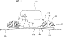
- FIG 12 is a partial enlarged view of the high-pressure air generation unit 5.
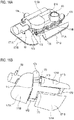
- FIG 13A shows a perspective view of the high-pressure air generation unit 5 connected to an adhesive unit 181, as seen from below.
- FIG. 13B shows a perspective view of the adhesive unit 181, as seen from below.
- FIG. 13C shows an exploded state of the members constituting the adhesive unit 181.
- the adhesive unit 181 includes a fixing member 181A, an adhesive member 181B, and a plurality of (three in this example) rubber dampers (an example of the connecting member) 181C.
- the fixing member 181A is formed in a plate shape and has a central plate 182 having a polygonal shape (regular hexagonal shape in this example), and a plurality of (three in this example) equally spaced attachment plates 183 extending continuously outward from an outer periphery of the central plate 182.
- the fixing member 181A is formed of an iron plate bracket, for example. Meanwhile, the fixing member 181A may be formed of a resin material.
- the adhesive member 181B constituted by, for example, a double-sided tape is attached on the surface (back surface) of the central plate 182 on the side facing the back door panel 200a.
- the adhesive member 181B includes an elastically deformable adhesion layer that has a predetermined thickness.
- the central plate 182 is fixed to the back door panel 200a via the adhesive member 181B.
- Each of the attachment plates 183 has an inclined portion 183A provided to be inclined, and a flat portion 183B provided parallel to the central plate 182.
- the flat portion 183B is provided with an attachment hole 184 to which the rubber damper 181C is attached.
- the inclined portion 183A is inclined upward such that a distance d in the vertical direction to the central plate 182 is increased away from the central plate 182.
- Each rubber damper 181C is formed of a rubber member having elasticity and is configured to connect the fixing member 181A and the housing 51. Meanwhile, the damper may be made of a resin having the same elasticity as the rubber damper 181C.
- the rubber damper 181C has a disc shape.
- a first groove 185A and a second groove 185B are provided on an outer peripheral portion of the rubber damper 181C.
- An inner peripheral portion of the attachment hole 184 of the attachment plate 183 of the fixing member 181A is fitted in the first groove 185A.
- An inner peripheral portion of the attachment hole 51D of the connecting portion 51C of the housing 51 is fitted in the second groove 185B.
- a through-hole 186 penetrating in the upper and lower direction is provided in the central portion of the rubber damper 181C. Further, the rubber damper 181C is provided with a crank-shaped portion 187 over the entire circumference of the rubber damper 181C.
- the housing 51 When attaching the housing 51 connected to the rubber dampers 181C to the back door panel 200a, the housing 51 is attached to the back door panel 200a via the fixing member 181A in surface contact with the back door panel 200a by elastically deforming the adhesive member 181B of the central plate 182 along at least a part of the surface shape of the back door panel 200a.
- the housing 51 is held in a state in which a sufficient gap h1 (see FIG. 12 ) is formed between the fixing member 181A and the housing 51.
- the housing 51 is connected to the rubber dampers 181C so that the position of the center of the housing 51 overlaps with the position of the center of the adhesive member 181B.
- the inclined portion 183A is inclined in a direction away from the back door panel 200a, in this example, a gap h2 is secured between the rubber dampers 181C and the back door panel 200a.
- the moving mechanism 65 inside the housing 51 is configured such that the piston 52 moves parallel to the surface where the fixing member 181A is attached to the back door panel 200a.
- the high-pressure air generation unit 5 is attached to the back door panel 200a in a state in which the gap h1 is formed between the back door panel 200a and the high-pressure air generation unit 5. Therefore, the sound and vibration due to the operation of the motor 55 of the high-pressure air generation unit 5 are reduced by the rubber dampers 181C capable of absorbing the vibration and are difficult to propagate to the back door panel 200a of the vehicle V. In this way, the sound and vibration due to the operation of the motor 55 of the high-pressure air generation unit 5 are prevented from being resonated by the back door panel 200a, and hence, the occurrence of abnormal noise can be suppressed.
- the plate-shaped adhesive member 181B including an elastically deformable adhesion layer can also function as a cushioning member. Therefore, the sound and vibration due to the operation of the motor 55 can be also buffered by the adhesive member 181B, so that the sound and vibration are further difficult to propagate to the back door panel 200a. In this way, the occurrence of abnormal noise due to the operation of the motor 55 is further suppressed.
- each rubber damper 181C is formed of an elastic member and is provided with the through-hole 186 and the crank-shaped portion 187, the rubber damper 181C is likely to be elastically deformed.
- Each of the plurality of rubber dampers 181C can disperse and reduce the sound and vibration due to the operation of the motor 55.
- each rubber damper 181C can disperse and reduce the impact.
- the housing 51 is connected to the rubber dampers 181C so that the position of the center of the housing 51 overlaps with the position of the center of the adhesive member 181B, the sound and vibration due to the operation of the motor 55 can be reduced by being equally dispersed to each of the rubber dampers 181C. Therefore, as compared with a case where sound and vibration are unevenly dispersed to the rubber dampers 181C, the occurrence of abnormal noise due to the operation of the motor 55 can be suppressed.
- the high-pressure air generation unit 5 is disposed at a position closer to the hinge mechanism 201 of the back door 200A than the in-vehicle camera 100, an impact force applied to the high-pressure air generation unit 5 at the time of opening and closing the back door 200A is small, as compared with a configuration in which the high-pressure air generation unit 5 is disposed at a position far from the hinge mechanism 201. In this way, it is possible to reduce a contact area for obtaining an adhesive force required for fixing the housing 51 on the back door panel 200a. Therefore, it is possible to further improve the versatility at the time of attaching the high-pressure air generation unit 5.
- the piston type moving mechanism 65 since the piston type moving mechanism 65 is adopted, high-pressure air can be generated by the small motor 55. Therefore, the high-pressure air generation unit 5 can be reduced in size and weight, and the sound and vibration due to the operation of the drive source can be reduced.
- the high-pressure air is continuously generated by moving the piston 52 at a high speed, it is possible to improve the performance of removing foreign matters from the lens 101.
- most of the reaction force applied to the housing 51 when the piston 52 is moved at a high speed is parallel to the surface (attaching surface) where the fixing member 181A is attached to the back door panel 200a, and the component of the reaction force in the direction intersecting with the attaching surface is relatively small. Therefore, for example, even when the piston 52 is continuously moved at a high speed and the reaction force at that time is continuously applied to the housing 51, the fixing member 181A is prevented from being detached from the back door panel 200a because the force of the component in the direction in which the fixing member 181A is detached from the back door panel 200a is small.
- a fixing member 191A may have a flange portion 192 that can be bent and deformed.
- a double-sided tape 191B is formed so as to correspond to the shape of the flange portion 192.
- the fixing member 191A is easily brought into contact with the back door panel 200a by being deformed following the curved portion or the uneven portion of the back door panel 200a particularly at the flange portion 192, the versatility during attachment is further improved.
- a fixing member 195A may have an attaching portion 193 to be attached by bolt fastening.
- the attaching portion 193 is formed of the same iron plate as the other portion of the fixing member 195A.
- the occurrence of abnormal noise due to the operation of the motor 55 can be suppressed by the rubber dampers 181C while securely fixing the fixing member 195A to the back door panel 200a by using a bolt.
- FIG. 15A shows the high-pressure air generation unit 5 attached to the back door panel 200a via an adhesive member 171.
- FIG. 15B is a plan view showing the high-pressure air generation unit 5 mounted on the adhesive member 171.
- FIGS.16A and 16B show a top perspective view and a bottom perspective view of FIG. 15B , respectively.
- FIGS. 17A and 17B are views in which the high-pressure air generation unit 5 in FIGS. 16A and 16B is removed, showing a perspective view of the adhesive member 171 as seen from above and a perspective view thereof as seen from below, respectively.
- the adhesive member 171 includes a fixing member 171A, an adhesion layer 171B, and a mounting portion 171C (see FIG. 17A ).
- the fixing member 171A is constituted by a plurality of (three in this example) plate-shaped members separated from each other.
- the adhesion layer 171B is formed on the surface of each fixing member 171A on the side facing the back door panel 200a.
- the adhesion layer 171B is formed of, for example, a double-sided tape having a predetermined thickness.
- the adhesion layer 171B is configured so as to be elastically deformable along at least a part of the surface shape of the back door panel 200a.
- the mounting portion (an example of the connecting member) 171C is a portion on which the housing 51 is mounted.
- the mounting portion 171C is formed continuously with each fixing member 171A via a continuous portion 173 formed so as to rise upward from each fixing member 171A. That is, the fixing members 171A are connected to each other via the mounting portion 171C and each continuous portion 173.
- the fixing member 171A and the mounting portion 171C are integrally formed of the same material.
- the mounting portion 171C is provided with a plurality of (three in this example) connecting portions 172 that connects the housing 51 and the mounting portion 171C.
- Each of the connecting portions 172 is configured to be elastically deformable (in a stepwise manner in this example).
- a planar attachment part 174 to which the housing 51 is attached is provided at a leading end of each connecting portion 172.
- Each attachment part 174 is provided in such a way that it is inclined in a direction away from the fixing member 171A as approaching its leading end.
- the attaching surface of each attachment part 174 is set at an inclination angle toward the center of gravity of the housing 51 (the high-pressure air generation unit 5) mounted thereon.
- the housing 51 having three attaching surfaces to be affixed to the attachment parts 174 is attached to the attachment parts 174 via an adhesive member such as a double-sided tape, for example.
- the housing 51 when attaching the housing 51 mounted on the mounting portion 171C of the adhesive member 171 to the back door panel 200a, the housing 51 is attached to the back door panel 200a via the adhesive member 171 in surface contact with the back door panel 200a by elastically deforming the adhesion layer 171B of the adhesive member 171.
- the housing 51 in a state of being mounted on the mounting portion 171C is held in a state in which a gap h3 (see FIG. 15A ) is formed between the fixing member 171 A and the housing 51.
- the housing 51 is formed in a substantially rectangular parallelepiped shape.
- the connector part 63 for supplying power to the motor 55 is formed on the upper surface 51A of the housing 51.
- the housing 51 is configured such that the lower surface 51B on the side opposite to the upper surface 51A on which the connector part 63 is formed is mounted on the mounting portion 171C of the adhesive member 171 so as to face the back door panel 200a.
- the adhesive member 171 is formed in a substantially plate shape.
- the adhesive member 171 is made of, for example, resin. Meanwhile, the adhesive member 171 may be made of metal.
- the fixing member 171A and the mounting portion 171C are integrally formed of the same material, the number of parts can be reduced and the cost can be reduced.
- the fixing member 171A is constituted by a plurality of plate-shaped members separated from each other. Therefore, even when an impact is applied to the housing 51 of the high-pressure air generation unit 5 due to, for example, an external factor such as when opening and closing the back door 200A, each of the plate-shaped members can disperse and reduce the impact.
- each attachment part 174 to which the housing 51 is attached is set at an inclination angle toward the center of gravity of the housing 51 (the high-pressure air generation unit 5). Therefore, the sound and vibration and the like can be effectively absorbed, so that it is possible to suppress the occurrence of abnormal noise due to the operation of the motor 55.
- the fixing member 171A is likely to be deformed along the curved portion or the uneven portion of the back door panel 200a, so that the versatility at the time of attaching the high-pressure air generation unit 5 can be further improved.
- the present invention is not limited to the above-described embodiments, but can be appropriately deformed or improved.
- the materials, shapes, dimensions, numerical values, modes, quantities, and locations and the like of the respective components in the above-described embodiments are arbitrary and not limited as long as they can achieve the present invention.
- the object to which the present invention is applied is not limited as long as it is a camera used outdoors.
- a camera mounted so as to be exposed to the outside of an airplane, a railroad, a ship, a robot, an outdoor installation object, a building and the like may be included.
Landscapes
- Engineering & Computer Science (AREA)
- Mechanical Engineering (AREA)
- General Engineering & Computer Science (AREA)
- Multimedia (AREA)
- Signal Processing (AREA)
- Combustion & Propulsion (AREA)
- Chemical & Material Sciences (AREA)
- Physics & Mathematics (AREA)
- Acoustics & Sound (AREA)
- Aviation & Aerospace Engineering (AREA)
- Studio Devices (AREA)
- Compressor (AREA)
- Compressors, Vaccum Pumps And Other Relevant Systems (AREA)
- Vibration Prevention Devices (AREA)
- Fittings On The Vehicle Exterior For Carrying Loads, And Devices For Holding Or Mounting Articles (AREA)
Applications Claiming Priority (3)
| Application Number | Priority Date | Filing Date | Title |
|---|---|---|---|
| JP2015131782 | 2015-06-30 | ||
| JP2015131781 | 2015-06-30 | ||
| PCT/JP2016/068573 WO2017002688A1 (ja) | 2015-06-30 | 2016-06-22 | 異物除去装置および当該異物除去装置を備える車両 |
Publications (3)
| Publication Number | Publication Date |
|---|---|
| EP3318453A1 true EP3318453A1 (de) | 2018-05-09 |
| EP3318453A4 EP3318453A4 (de) | 2019-03-27 |
| EP3318453B1 EP3318453B1 (de) | 2020-11-18 |
Family
ID=57608182
Family Applications (1)
| Application Number | Title | Priority Date | Filing Date |
|---|---|---|---|
| EP16817796.2A Active EP3318453B1 (de) | 2015-06-30 | 2016-06-22 | Fremdstoffbeseitigungsvorrichtung und damit ausgestattetes fahrzeug |
Country Status (5)
| Country | Link |
|---|---|
| US (1) | US10556571B2 (de) |
| EP (1) | EP3318453B1 (de) |
| JP (1) | JP6766043B2 (de) |
| CN (1) | CN107709105B (de) |
| WO (1) | WO2017002688A1 (de) |
Cited By (1)
| Publication number | Priority date | Publication date | Assignee | Title |
|---|---|---|---|---|
| CN107433915A (zh) * | 2017-07-07 | 2017-12-05 | 浙江大华技术股份有限公司 | 一种外置车载摄像装置和车辆 |
Families Citing this family (4)
| Publication number | Priority date | Publication date | Assignee | Title |
|---|---|---|---|---|
| JP7153462B2 (ja) * | 2017-07-31 | 2022-10-14 | 株式会社デンソーテン | 駆動装置の取付構造 |
| CN111032453B (zh) * | 2017-08-30 | 2023-10-20 | 株式会社小糸制作所 | 车辆用清洁器单元及带摄像头的转向指示灯 |
| DK180429B1 (en) * | 2018-11-20 | 2021-04-23 | Motional Ad Llc | Self-cleaning sensor housings |
| JP7470055B2 (ja) * | 2019-02-01 | 2024-04-17 | 株式会社小糸製作所 | 車両用クリーナ |
Family Cites Families (19)
| Publication number | Priority date | Publication date | Assignee | Title |
|---|---|---|---|---|
| JPH03102652A (ja) * | 1989-09-18 | 1991-04-30 | Canon Inc | 光学的情報記録再生装置 |
| US5546630A (en) | 1995-01-04 | 1996-08-20 | Long; Andre | Blast wiper for motor vehicle lights |
| CN2298172Y (zh) | 1997-04-22 | 1998-11-25 | 程元辉 | 汽车后景监视装置 |
| JPH11255018A (ja) * | 1998-03-11 | 1999-09-21 | Komatsu Ltd | 車両用後方監視カメラの洗浄装置 |
| JP2001171491A (ja) | 1999-12-16 | 2001-06-26 | Matsushita Electric Ind Co Ltd | 車載カメラ装置及び車載カメラの洗浄方法 |
| ATE340720T1 (de) | 2001-08-31 | 2006-10-15 | Kautex Textron Gmbh & Co Kg | Scheinwerferreinigungsanlage |
| JP2009083730A (ja) * | 2007-10-01 | 2009-04-23 | Panasonic Corp | 車載カメラ |
| JP4513889B2 (ja) * | 2008-04-03 | 2010-07-28 | 株式会社日本自動車部品総合研究所 | ウォッシャノズル付カメラおよびウォッシャノズル |
| RU2455177C2 (ru) | 2009-09-29 | 2012-07-10 | Денсо Корпорейшн | Оболочка бортового оптического сенсора и устройство бортового оптического сенсора |
| JP5056919B2 (ja) | 2009-09-29 | 2012-10-24 | 株式会社デンソー | 車載光学センサカバー及び車載光学センサ装置 |
| US20120117745A1 (en) | 2009-09-29 | 2012-05-17 | Denso Corporation | On-board optical sensor cover and on-board optical sensor apparatus |
| JP2012201122A (ja) | 2011-03-23 | 2012-10-22 | Asmo Co Ltd | 車載カメラ用ノズル装置、清掃装置付き車載カメラ、及び車載カメラ用清掃システム |
| JP5494743B2 (ja) | 2011-10-14 | 2014-05-21 | 株式会社デンソー | カメラ洗浄装置 |
| US9707896B2 (en) * | 2012-10-15 | 2017-07-18 | Magna Electronics Inc. | Vehicle camera lens dirt protection via air flow |
| US20150114431A1 (en) | 2013-10-31 | 2015-04-30 | Glacial Blaster, Inc. | Air blast wiper system and method |
| JP6551962B2 (ja) | 2013-11-28 | 2019-07-31 | Necエンベデッドプロダクツ株式会社 | 車載カメラの洗浄装置及び車載カメラの洗浄方法 |
| CN106163888B (zh) | 2014-04-14 | 2019-06-28 | 株式会社小糸制作所 | 异物除去装置 |
| EP2949520B1 (de) | 2014-05-27 | 2018-03-21 | Fico Transpar, S.A. | System zur Reinigung von an einem Fahrzeug montierten optischen Linsen |
| US10059280B2 (en) * | 2014-06-06 | 2018-08-28 | Joseph Richard Cooper | Obstruction-removal system and method for vehicle-camera lens |
-
2016
- 2016-06-22 EP EP16817796.2A patent/EP3318453B1/de active Active
- 2016-06-22 US US15/740,936 patent/US10556571B2/en active Active
- 2016-06-22 CN CN201680038229.1A patent/CN107709105B/zh active Active
- 2016-06-22 WO PCT/JP2016/068573 patent/WO2017002688A1/ja not_active Ceased
- 2016-06-22 JP JP2017526307A patent/JP6766043B2/ja active Active
Cited By (1)
| Publication number | Priority date | Publication date | Assignee | Title |
|---|---|---|---|---|
| CN107433915A (zh) * | 2017-07-07 | 2017-12-05 | 浙江大华技术股份有限公司 | 一种外置车载摄像装置和车辆 |
Also Published As
| Publication number | Publication date |
|---|---|
| EP3318453B1 (de) | 2020-11-18 |
| US10556571B2 (en) | 2020-02-11 |
| CN107709105B (zh) | 2020-09-08 |
| US20180194331A1 (en) | 2018-07-12 |
| JP6766043B2 (ja) | 2020-10-07 |
| CN107709105A (zh) | 2018-02-16 |
| JPWO2017002688A1 (ja) | 2018-06-21 |
| WO2017002688A1 (ja) | 2017-01-05 |
| EP3318453A4 (de) | 2019-03-27 |
Similar Documents
| Publication | Publication Date | Title |
|---|---|---|
| EP3318453A1 (de) | Fremdstoffbeseitigungsvorrichtung und damit ausgestattetes fahrzeug | |
| US20210362689A1 (en) | Foreign material removing device and vehicle provided with this foreign material removing device | |
| EP3318454B1 (de) | Fremdstoffbeseitigungsvorrichtung und damit ausgestattetes fahrzeug | |
| CN110214098B (zh) | 用于车辆的外部环境检测装置的安装结构 | |
| US10661761B2 (en) | Foreign matter removal device and vehicle equipped with foreign matter removal device | |
| US11535174B2 (en) | External sensor attachment portion structure | |
| JP5627435B2 (ja) | 電力制御装置の保護装置 | |
| JP5899182B2 (ja) | 電気車両 | |
| US7988224B2 (en) | Cowl cover assembly for a motor vehicle | |
| CN111605402A (zh) | 平视显示器装置及平视显示器装置的安装构造 | |
| JP5468163B2 (ja) | 自動車のボディシェルにバッテリモジュールを固定するためのデバイス | |
| JP4728906B2 (ja) | 車両のスポイラ構造 | |
| JP5195657B2 (ja) | バンパカバー支持構造 | |
| CN116533890B (zh) | 激光雷达支架和车辆 | |
| JP2012144125A (ja) | 車両用導風ガイド構造 | |
| JP5268702B2 (ja) | 車体前部構造 | |
| JP2005132325A (ja) | 車体のリアバンパー組立構造 | |
| CN109664948B (zh) | 车辆前部构造 | |
| JP4669743B2 (ja) | 自動車の前部車体構造 | |
| CN105916741A (zh) | 气囊装置 | |
| JP6460164B2 (ja) | 自動車の前部構造 | |
| WO2017002191A1 (ja) | Ecuブラケット及び車両 | |
| JP2017206044A (ja) | キャブの前面部構造 | |
| KR20130002782A (ko) | 펜더 조립 구조 및 방법 | |
| JP6624010B2 (ja) | 車両の前部構造 |
Legal Events
| Date | Code | Title | Description |
|---|---|---|---|
| STAA | Information on the status of an ep patent application or granted ep patent |
Free format text: STATUS: THE INTERNATIONAL PUBLICATION HAS BEEN MADE |
|
| PUAI | Public reference made under article 153(3) epc to a published international application that has entered the european phase |
Free format text: ORIGINAL CODE: 0009012 |
|
| STAA | Information on the status of an ep patent application or granted ep patent |
Free format text: STATUS: REQUEST FOR EXAMINATION WAS MADE |
|
| 17P | Request for examination filed |
Effective date: 20171228 |
|
| AK | Designated contracting states |
Kind code of ref document: A1 Designated state(s): AL AT BE BG CH CY CZ DE DK EE ES FI FR GB GR HR HU IE IS IT LI LT LU LV MC MK MT NL NO PL PT RO RS SE SI SK SM TR |
|
| AX | Request for extension of the european patent |
Extension state: BA ME |
|
| DAV | Request for validation of the european patent (deleted) | ||
| DAX | Request for extension of the european patent (deleted) | ||
| A4 | Supplementary search report drawn up and despatched |
Effective date: 20190222 |
|
| RIC1 | Information provided on ipc code assigned before grant |
Ipc: H04N 5/225 20060101ALI20190218BHEP Ipc: H04N 7/18 20060101ALI20190218BHEP Ipc: B60R 1/00 20060101AFI20190218BHEP Ipc: B60S 1/56 20060101ALI20190218BHEP Ipc: B60S 1/54 20060101ALI20190218BHEP |
|
| REG | Reference to a national code |
Ref country code: DE Ref legal event code: R079 Ref document number: 602016048212 Country of ref document: DE Free format text: PREVIOUS MAIN CLASS: B60S0001600000 Ipc: B60R0001000000 |
|
| RIC1 | Information provided on ipc code assigned before grant |
Ipc: B60S 1/56 20060101ALI20200608BHEP Ipc: H04N 7/18 20060101ALI20200608BHEP Ipc: B60S 1/54 20060101ALI20200608BHEP Ipc: H04N 5/225 20060101ALI20200608BHEP Ipc: B60R 1/00 20060101AFI20200608BHEP |
|
| GRAP | Despatch of communication of intention to grant a patent |
Free format text: ORIGINAL CODE: EPIDOSNIGR1 |
|
| STAA | Information on the status of an ep patent application or granted ep patent |
Free format text: STATUS: GRANT OF PATENT IS INTENDED |
|
| INTG | Intention to grant announced |
Effective date: 20200803 |
|
| GRAS | Grant fee paid |
Free format text: ORIGINAL CODE: EPIDOSNIGR3 |
|
| GRAA | (expected) grant |
Free format text: ORIGINAL CODE: 0009210 |
|
| STAA | Information on the status of an ep patent application or granted ep patent |
Free format text: STATUS: THE PATENT HAS BEEN GRANTED |
|
| AK | Designated contracting states |
Kind code of ref document: B1 Designated state(s): AL AT BE BG CH CY CZ DE DK EE ES FI FR GB GR HR HU IE IS IT LI LT LU LV MC MK MT NL NO PL PT RO RS SE SI SK SM TR |
|
| REG | Reference to a national code |
Ref country code: GB Ref legal event code: FG4D |
|
| REG | Reference to a national code |
Ref country code: CH Ref legal event code: EP |
|
| REG | Reference to a national code |
Ref country code: DE Ref legal event code: R096 Ref document number: 602016048212 Country of ref document: DE |
|
| REG | Reference to a national code |
Ref country code: IE Ref legal event code: FG4D |
|
| REG | Reference to a national code |
Ref country code: AT Ref legal event code: REF Ref document number: 1335416 Country of ref document: AT Kind code of ref document: T Effective date: 20201215 |
|
| REG | Reference to a national code |
Ref country code: AT Ref legal event code: MK05 Ref document number: 1335416 Country of ref document: AT Kind code of ref document: T Effective date: 20201118 |
|
| REG | Reference to a national code |
Ref country code: NL Ref legal event code: MP Effective date: 20201118 |
|
| PG25 | Lapsed in a contracting state [announced via postgrant information from national office to epo] |
Ref country code: FI Free format text: LAPSE BECAUSE OF FAILURE TO SUBMIT A TRANSLATION OF THE DESCRIPTION OR TO PAY THE FEE WITHIN THE PRESCRIBED TIME-LIMIT Effective date: 20201118 Ref country code: GR Free format text: LAPSE BECAUSE OF FAILURE TO SUBMIT A TRANSLATION OF THE DESCRIPTION OR TO PAY THE FEE WITHIN THE PRESCRIBED TIME-LIMIT Effective date: 20210219 Ref country code: PT Free format text: LAPSE BECAUSE OF FAILURE TO SUBMIT A TRANSLATION OF THE DESCRIPTION OR TO PAY THE FEE WITHIN THE PRESCRIBED TIME-LIMIT Effective date: 20210318 Ref country code: RS Free format text: LAPSE BECAUSE OF FAILURE TO SUBMIT A TRANSLATION OF THE DESCRIPTION OR TO PAY THE FEE WITHIN THE PRESCRIBED TIME-LIMIT Effective date: 20201118 Ref country code: NO Free format text: LAPSE BECAUSE OF FAILURE TO SUBMIT A TRANSLATION OF THE DESCRIPTION OR TO PAY THE FEE WITHIN THE PRESCRIBED TIME-LIMIT Effective date: 20210218 |
|
| PG25 | Lapsed in a contracting state [announced via postgrant information from national office to epo] |
Ref country code: IS Free format text: LAPSE BECAUSE OF FAILURE TO SUBMIT A TRANSLATION OF THE DESCRIPTION OR TO PAY THE FEE WITHIN THE PRESCRIBED TIME-LIMIT Effective date: 20210318 Ref country code: PL Free format text: LAPSE BECAUSE OF FAILURE TO SUBMIT A TRANSLATION OF THE DESCRIPTION OR TO PAY THE FEE WITHIN THE PRESCRIBED TIME-LIMIT Effective date: 20201118 Ref country code: LV Free format text: LAPSE BECAUSE OF FAILURE TO SUBMIT A TRANSLATION OF THE DESCRIPTION OR TO PAY THE FEE WITHIN THE PRESCRIBED TIME-LIMIT Effective date: 20201118 Ref country code: BG Free format text: LAPSE BECAUSE OF FAILURE TO SUBMIT A TRANSLATION OF THE DESCRIPTION OR TO PAY THE FEE WITHIN THE PRESCRIBED TIME-LIMIT Effective date: 20210218 Ref country code: AT Free format text: LAPSE BECAUSE OF FAILURE TO SUBMIT A TRANSLATION OF THE DESCRIPTION OR TO PAY THE FEE WITHIN THE PRESCRIBED TIME-LIMIT Effective date: 20201118 Ref country code: SE Free format text: LAPSE BECAUSE OF FAILURE TO SUBMIT A TRANSLATION OF THE DESCRIPTION OR TO PAY THE FEE WITHIN THE PRESCRIBED TIME-LIMIT Effective date: 20201118 |
|
| REG | Reference to a national code |
Ref country code: LT Ref legal event code: MG9D |
|
| PG25 | Lapsed in a contracting state [announced via postgrant information from national office to epo] |
Ref country code: HR Free format text: LAPSE BECAUSE OF FAILURE TO SUBMIT A TRANSLATION OF THE DESCRIPTION OR TO PAY THE FEE WITHIN THE PRESCRIBED TIME-LIMIT Effective date: 20201118 |
|
| PG25 | Lapsed in a contracting state [announced via postgrant information from national office to epo] |
Ref country code: CZ Free format text: LAPSE BECAUSE OF FAILURE TO SUBMIT A TRANSLATION OF THE DESCRIPTION OR TO PAY THE FEE WITHIN THE PRESCRIBED TIME-LIMIT Effective date: 20201118 Ref country code: EE Free format text: LAPSE BECAUSE OF FAILURE TO SUBMIT A TRANSLATION OF THE DESCRIPTION OR TO PAY THE FEE WITHIN THE PRESCRIBED TIME-LIMIT Effective date: 20201118 Ref country code: SM Free format text: LAPSE BECAUSE OF FAILURE TO SUBMIT A TRANSLATION OF THE DESCRIPTION OR TO PAY THE FEE WITHIN THE PRESCRIBED TIME-LIMIT Effective date: 20201118 Ref country code: LT Free format text: LAPSE BECAUSE OF FAILURE TO SUBMIT A TRANSLATION OF THE DESCRIPTION OR TO PAY THE FEE WITHIN THE PRESCRIBED TIME-LIMIT Effective date: 20201118 Ref country code: SK Free format text: LAPSE BECAUSE OF FAILURE TO SUBMIT A TRANSLATION OF THE DESCRIPTION OR TO PAY THE FEE WITHIN THE PRESCRIBED TIME-LIMIT Effective date: 20201118 Ref country code: RO Free format text: LAPSE BECAUSE OF FAILURE TO SUBMIT A TRANSLATION OF THE DESCRIPTION OR TO PAY THE FEE WITHIN THE PRESCRIBED TIME-LIMIT Effective date: 20201118 |
|
| REG | Reference to a national code |
Ref country code: DE Ref legal event code: R097 Ref document number: 602016048212 Country of ref document: DE |
|
| PG25 | Lapsed in a contracting state [announced via postgrant information from national office to epo] |
Ref country code: DK Free format text: LAPSE BECAUSE OF FAILURE TO SUBMIT A TRANSLATION OF THE DESCRIPTION OR TO PAY THE FEE WITHIN THE PRESCRIBED TIME-LIMIT Effective date: 20201118 |
|
| PLBE | No opposition filed within time limit |
Free format text: ORIGINAL CODE: 0009261 |
|
| STAA | Information on the status of an ep patent application or granted ep patent |
Free format text: STATUS: NO OPPOSITION FILED WITHIN TIME LIMIT |
|
| 26N | No opposition filed |
Effective date: 20210819 |
|
| PG25 | Lapsed in a contracting state [announced via postgrant information from national office to epo] |
Ref country code: AL Free format text: LAPSE BECAUSE OF FAILURE TO SUBMIT A TRANSLATION OF THE DESCRIPTION OR TO PAY THE FEE WITHIN THE PRESCRIBED TIME-LIMIT Effective date: 20201118 Ref country code: NL Free format text: LAPSE BECAUSE OF FAILURE TO SUBMIT A TRANSLATION OF THE DESCRIPTION OR TO PAY THE FEE WITHIN THE PRESCRIBED TIME-LIMIT Effective date: 20201118 Ref country code: IT Free format text: LAPSE BECAUSE OF FAILURE TO SUBMIT A TRANSLATION OF THE DESCRIPTION OR TO PAY THE FEE WITHIN THE PRESCRIBED TIME-LIMIT Effective date: 20201118 |
|
| PG25 | Lapsed in a contracting state [announced via postgrant information from national office to epo] |
Ref country code: SI Free format text: LAPSE BECAUSE OF FAILURE TO SUBMIT A TRANSLATION OF THE DESCRIPTION OR TO PAY THE FEE WITHIN THE PRESCRIBED TIME-LIMIT Effective date: 20201118 |
|
| PG25 | Lapsed in a contracting state [announced via postgrant information from national office to epo] |
Ref country code: ES Free format text: LAPSE BECAUSE OF FAILURE TO SUBMIT A TRANSLATION OF THE DESCRIPTION OR TO PAY THE FEE WITHIN THE PRESCRIBED TIME-LIMIT Effective date: 20201118 Ref country code: MC Free format text: LAPSE BECAUSE OF FAILURE TO SUBMIT A TRANSLATION OF THE DESCRIPTION OR TO PAY THE FEE WITHIN THE PRESCRIBED TIME-LIMIT Effective date: 20201118 |
|
| REG | Reference to a national code |
Ref country code: CH Ref legal event code: PL |
|
| GBPC | Gb: european patent ceased through non-payment of renewal fee |
Effective date: 20210622 |
|
| REG | Reference to a national code |
Ref country code: BE Ref legal event code: MM Effective date: 20210630 |
|
| PG25 | Lapsed in a contracting state [announced via postgrant information from national office to epo] |
Ref country code: LU Free format text: LAPSE BECAUSE OF NON-PAYMENT OF DUE FEES Effective date: 20210622 |
|
| PG25 | Lapsed in a contracting state [announced via postgrant information from national office to epo] |
Ref country code: LI Free format text: LAPSE BECAUSE OF NON-PAYMENT OF DUE FEES Effective date: 20210630 Ref country code: IE Free format text: LAPSE BECAUSE OF NON-PAYMENT OF DUE FEES Effective date: 20210622 Ref country code: GB Free format text: LAPSE BECAUSE OF NON-PAYMENT OF DUE FEES Effective date: 20210622 Ref country code: CH Free format text: LAPSE BECAUSE OF NON-PAYMENT OF DUE FEES Effective date: 20210630 |
|
| PG25 | Lapsed in a contracting state [announced via postgrant information from national office to epo] |
Ref country code: IS Free format text: LAPSE BECAUSE OF FAILURE TO SUBMIT A TRANSLATION OF THE DESCRIPTION OR TO PAY THE FEE WITHIN THE PRESCRIBED TIME-LIMIT Effective date: 20210318 |
|
| PG25 | Lapsed in a contracting state [announced via postgrant information from national office to epo] |
Ref country code: BE Free format text: LAPSE BECAUSE OF NON-PAYMENT OF DUE FEES Effective date: 20210630 |
|
| P01 | Opt-out of the competence of the unified patent court (upc) registered |
Effective date: 20230509 |
|
| PG25 | Lapsed in a contracting state [announced via postgrant information from national office to epo] |
Ref country code: CY Free format text: LAPSE BECAUSE OF FAILURE TO SUBMIT A TRANSLATION OF THE DESCRIPTION OR TO PAY THE FEE WITHIN THE PRESCRIBED TIME-LIMIT Effective date: 20201118 |
|
| PG25 | Lapsed in a contracting state [announced via postgrant information from national office to epo] |
Ref country code: HU Free format text: LAPSE BECAUSE OF FAILURE TO SUBMIT A TRANSLATION OF THE DESCRIPTION OR TO PAY THE FEE WITHIN THE PRESCRIBED TIME-LIMIT; INVALID AB INITIO Effective date: 20160622 |
|
| PG25 | Lapsed in a contracting state [announced via postgrant information from national office to epo] |
Ref country code: MK Free format text: LAPSE BECAUSE OF FAILURE TO SUBMIT A TRANSLATION OF THE DESCRIPTION OR TO PAY THE FEE WITHIN THE PRESCRIBED TIME-LIMIT Effective date: 20201118 |
|
| PG25 | Lapsed in a contracting state [announced via postgrant information from national office to epo] |
Ref country code: TR Free format text: LAPSE BECAUSE OF FAILURE TO SUBMIT A TRANSLATION OF THE DESCRIPTION OR TO PAY THE FEE WITHIN THE PRESCRIBED TIME-LIMIT Effective date: 20201118 |
|
| PG25 | Lapsed in a contracting state [announced via postgrant information from national office to epo] |
Ref country code: MT Free format text: LAPSE BECAUSE OF FAILURE TO SUBMIT A TRANSLATION OF THE DESCRIPTION OR TO PAY THE FEE WITHIN THE PRESCRIBED TIME-LIMIT Effective date: 20201118 |
|
| PGFP | Annual fee paid to national office [announced via postgrant information from national office to epo] |
Ref country code: DE Payment date: 20250429 Year of fee payment: 10 |
|
| PGFP | Annual fee paid to national office [announced via postgrant information from national office to epo] |
Ref country code: FR Payment date: 20250508 Year of fee payment: 10 |