EP3318744B1 - Moteur-fusée à liquide utilisant une pompe entraînée par un moteur électrique - Google Patents
Moteur-fusée à liquide utilisant une pompe entraînée par un moteur électrique Download PDFInfo
- Publication number
- EP3318744B1 EP3318744B1 EP16846860.1A EP16846860A EP3318744B1 EP 3318744 B1 EP3318744 B1 EP 3318744B1 EP 16846860 A EP16846860 A EP 16846860A EP 3318744 B1 EP3318744 B1 EP 3318744B1
- Authority
- EP
- European Patent Office
- Prior art keywords
- oxidant
- fuel
- electric motor
- line
- pump
- Prior art date
- Legal status (The legal status is an assumption and is not a legal conclusion. Google has not performed a legal analysis and makes no representation as to the accuracy of the status listed.)
- Active
Links
Images


Classifications
-
- F—MECHANICAL ENGINEERING; LIGHTING; HEATING; WEAPONS; BLASTING
- F02—COMBUSTION ENGINES; HOT-GAS OR COMBUSTION-PRODUCT ENGINE PLANTS
- F02K—JET-PROPULSION PLANTS
- F02K9/00—Rocket-engine plants, i.e. plants carrying both fuel and oxidant therefor; Control thereof
- F02K9/42—Rocket-engine plants, i.e. plants carrying both fuel and oxidant therefor; Control thereof using liquid or gaseous propellants
- F02K9/44—Feeding propellants
- F02K9/46—Feeding propellants using pumps
-
- F—MECHANICAL ENGINEERING; LIGHTING; HEATING; WEAPONS; BLASTING
- F02—COMBUSTION ENGINES; HOT-GAS OR COMBUSTION-PRODUCT ENGINE PLANTS
- F02K—JET-PROPULSION PLANTS
- F02K9/00—Rocket-engine plants, i.e. plants carrying both fuel and oxidant therefor; Control thereof
- F02K9/42—Rocket-engine plants, i.e. plants carrying both fuel and oxidant therefor; Control thereof using liquid or gaseous propellants
- F02K9/44—Feeding propellants
- F02K9/56—Control
-
- F—MECHANICAL ENGINEERING; LIGHTING; HEATING; WEAPONS; BLASTING
- F02—COMBUSTION ENGINES; HOT-GAS OR COMBUSTION-PRODUCT ENGINE PLANTS
- F02K—JET-PROPULSION PLANTS
- F02K9/00—Rocket-engine plants, i.e. plants carrying both fuel and oxidant therefor; Control thereof
- F02K9/95—Rocket-engine plants, i.e. plants carrying both fuel and oxidant therefor; Control thereof characterised by starting or ignition means or arrangements
-
- H—ELECTRICITY
- H02—GENERATION; CONVERSION OR DISTRIBUTION OF ELECTRIC POWER
- H02K—DYNAMO-ELECTRIC MACHINES
- H02K5/00—Casings; Enclosures; Supports
- H02K5/04—Casings or enclosures characterised by the shape, form or construction thereof
- H02K5/20—Casings or enclosures characterised by the shape, form or construction thereof with channels or ducts for flow of cooling medium
- H02K5/203—Casings or enclosures characterised by the shape, form or construction thereof with channels or ducts for flow of cooling medium specially adapted for liquids, e.g. cooling jackets
-
- F—MECHANICAL ENGINEERING; LIGHTING; HEATING; WEAPONS; BLASTING
- F05—INDEXING SCHEMES RELATING TO ENGINES OR PUMPS IN VARIOUS SUBCLASSES OF CLASSES F01-F04
- F05D—INDEXING SCHEME FOR ASPECTS RELATING TO NON-POSITIVE-DISPLACEMENT MACHINES OR ENGINES, GAS-TURBINES OR JET-PROPULSION PLANTS
- F05D2260/00—Function
- F05D2260/20—Heat transfer, e.g. cooling
- F05D2260/205—Cooling fluid recirculation, i.e. after cooling one or more components is the cooling fluid recovered and used elsewhere for other purposes
Definitions
- the present invention relates to a liquid rocket engine using a pump driven by an electric motor, according to the preamble of claim 1.
- turbopump type engines for rockets which use a liquid propellant, send an oxidant and a fuel at a high pressure to a main combustor by using a high-temperature gas generated from a gas generator, thereby generating thrust.
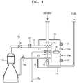
- a turbopump type engine for a rocket which uses a liquid propellant includes a main combustor 11 to combust an oxidant and a fuel, a main oxidant line 12 to guide an oxidant to the main combustor 11, a main fuel line 13 to guide a fuel to the main combustor 11, a gas generator 14 to generate a high-temperature and high-pressure gas, an auxiliary oxidant line 15 to guide a part of the oxidant to the gas generator 14, an auxiliary fuel line 16 to guide a part of the fuel to the gas generator 14, a turbine 17 to be rotated by the high-temperature and high-pressure gas of the gas generator 14, and an oxidant pump 18 and a fuel pump 19 that are coupled uniaxially to the turbine 17.
- the turbopump type engine for a rocket which uses a liquid propellant includes a main oxidant opening/closing valve 12a to turn on/off the oxidant guided to the main combustor 11, a main fuel opening/closing valve 13a to turn on/off the fuel guided to the main combustor 11, an auxiliary oxidant opening/closing valve 15a to turn on/off the oxidant guided to the gas generator 14, an auxiliary fuel opening/closing valve 16a to turn on/off the fuel guided to the gas generator 14, and a gas discharge pipe 17a to discharge gas passed through the turbine 17 to the outside.
- reference numeral "22” denotes a pyro starter or a turbine starter.
- the turbine 17 is driven by the turbine starter 22 to increase a pressure via the oxidant pump 18 and the fuel pump 19.
- the auxiliary oxidant valve 15a and the auxiliary fuel valve 16a are opened to supply the oxidant and the fuel (hereinafter, referred to as "propellant") to the gas generator 14.
- the supplied propellant is combusted in the gas generator 14 to generate a combustion gas, and the turbine 17 is driven again by a high-temperature combustion gas to rotate the oxidant pump 18 and the fuel pump 19 (hereinafter, collectively referred to as "pumps").
- the gas generator 14 is driven to open the main oxidant valve 12a and the main fuel valve 13a (hereinafter, collectively referred to as "main valves") when the pumps 18 and 19 produce a certain degree of pressure to supply the propellant to the main combustor 11.
- the supplied propellant is combusted in the main combustor 11 to be discharged as a high-temperature gas via nozzles to the outside.
- the turbopump type engine is started through these processes.
- the oxidant and the fuel need to be further loaded to drive the gas generator, and thus a launch weight is increased.
- a gas that drives the turbine is thrown out, and thus, energy loss occurs.
- Laid-open publication US 2014/0283499 A1 discloses a turbopump type engine which comprises an electric pump within a liquid oxygen tank to pump liquid oxygen, and an electric pump within a liquid hydrogen tank to pump liquid hydrogen.
- Patent publication US 6,457,306 B1 and laid-open publication US 2014/0260186 A1 disclose a liquid rocket engine according to the preamble of claim 1 that does not include a gas generator and a turbine assembly and includes an electric motor for driving a liquid propellant pump. However, a member for cooling the electric motor is not disclosed there, and thus a configuration for cooling an overheated electric motor or a battery for supplying power to a motor is needed.
- the invention solves this problem by providing a liquid rocked engine having the features of claim 1.
- Advantageous embodiments of the invention are mentioned in the dependent claims, the wording of which is herewith incorporated into the description by reference.
- the liquid rocked engine of the invention uses a pump driven by an electric motor instead of using a gas generator and a turbine so that a system may be simplified, and overheated electric motor may be efficiently cooled by circulating a propellant (an oxidant or a fuel).
- a pump in a liquid rocket engine using a pump driven by an electric motor and having the above-described configuration, a pump is driven by an electric motor instead of using a gas generator and a turbine, and thus, the amount of a propellant may be decreased, and an overheated electric motor may be efficiently cooled by circulating the propellant.
- An embodiment of the present invention provides a liquid rocket engine using a pump driven by an electric motor, the liquid rocket engine including: a main combustor to receive and combust an oxidant and a fuel; a main oxidant line to guide the oxidant accommodated in an oxidant tank to the main combustor; a main fuel line to guide the fuel accommodated in a fuel tank to the main combustor; an oxidant pump positioned at the main oxidant line; a fuel pump positioned at the main fuel line; an electric motor positioned between the oxidant pump and the fuel pump to uniaxially drive the oxidant pump and the fuel pump; a cooling line branched from a side of the main oxidant line to guide a part of the oxidant to the electric motor, or branched from a side of the main fuel line to guide a part of the fuel to the electric motor; a cooling part connected to the cooling line so as to allow fluid flow therebetween; and a condenser installed at the cooling line, in which
- an end of the cooling line may be branched from the main oxidant line between the main combustor and the oxidant pump, and another end thereof may be connected to the main oxidant line between the oxidant pump and the oxidant tank.
- an end of the cooling line may be branched from the main fuel line between the main combustor and the fuel pump, and another end thereof may be connected to the main fuel line between the fuel pump and the fuel tank.
- an end of the cooling line is connected to the oxidant pump and another end thereof is exposed to the outside, and thus the oxidant leaked from the oxidant pump may be heat-exchanged with the electric motor and discharged to the outside.
- At least one of the oxidant and the fuel may pass through the cooling part and then be condensed in the condenser.
- liquid rocket engine may further include an opening/closing valve positioned between the end of the cooling line and the electric motor.
- the cooling part may have a barrel shape to accommodate the electric motor and have a flow path therein.
- the liquid rocket engine may further include a gear box positioned between the electric motor and the oxidant pump to adjust a rotational speed of the oxidant pump, or positioned between the electric motor and the fuel pump to adjust a rotational speed of the fuel pump.
- the cooling part may have a coil shape wound on an outer circumferential surface of the electric motor, and be connected to the end of the cooling line and the other end of the cooling line.
- liquid rocket engine may further include a battery connected to a side of the cooling line and supplying power to the electric motor.
- liquid rocket engine may further include an igniter connected to the battery, and installed at a side of the main combustor to ignite the main combustor by electric spark.
- FIG. 1A is a conceptual view illustrating a structure of a liquid rocket engine 100 using a pump driven by an electric motor, according to a first embodiment of the present invention
- FIGS. 1B and 1C which correspond to FIG. 1A , are conceptual views respectively illustrating structures of liquid rocket engines 100 according to second and third embodiments of the present invention
- FIG. 2 is a longitudinal sectional view illustrating a structure of an electric motor casing for cooling according to the present invention.
- the liquid rocket engine 100 using a pump driven by an electric motor includes an electric motor instead of a turbine and a gas generator of an existing liquid rocket engine.
- the amount of a propellant (an oxidant and a fuel) further loaded to drive the gas generator may be reduced.
- the liquid rocket engine 100 further includes a cooling line and a cooling part to cool the electric motor.
- the liquid rocket engine 100 using a pump driven by an electric motor includes a main combustor 101 to receive and combust an oxidant and a fuel, a main oxidant line 110 to guide the oxidant accommodated in an oxidant tank to the main combustor 101, a main fuel line 120 to guide the fuel accommodated in a fuel tank to the main combustor, an oxidant pump 130 and a fuel pump 135 that are respectively installed at the main oxidant line 110 and the main fuel line 120, an electric motor 150 to drive the oxidant pump 130 and the fuel pump 135, a battery 151 to supply power to the electric motor 150, a cooling line 170, and a cooling part.
- a main combustor 101 to receive and combust an oxidant and a fuel
- a main oxidant line 110 to guide the oxidant accommodated in an oxidant tank to the main combustor 101
- a main fuel line 120 to guide the fuel accommodated in a fuel tank to the main combu
- the liquid rocket engine 100 includes a main oxidant opening/closing valve 115 to turn on/off the oxidant guided to the main combustor 101 and a main fuel opening/closing valve 121 to turn on/off the fuel guided to the main combustor 101.
- a process of operating the liquid rocket engine 100 using a pump driven by an electric motor according to the present invention will now be described.
- the electric motor 150 is driven when the main oxidant opening/closing valve 115 and the main fuel opening/closing valve 121 are opened, the oxidant and the fuel are supplied to the main combustor 101 via the main oxidant line 110 and the main fuel line 120, respectively, while the oxidant pump 130 and the fuel pump 135 are rotated.
- the oxidant and the fuel supplied to the main combustor 101 are combusted, converted into a high-temperature gas, and discharged to the outside.
- the electric motor 150 is overheated when continuously driven, and thus the cooling line 170 and the cooling part, which have been described above, are configured to cool the overheated electric motor 150.
- the cooling line 170 is connected to a side of the main oxidant line 110 so as to allow fluid flow therebetween and guides a part of the oxidant to the electric motor 150, and may include a supply part 171 to supply the oxidant to the cooling part, and a discharge part 175 to guide the oxidant discharged from the cooling part.
- the supply part 171 may be configured such that a cooling line opening/closing valve 173 is installed to supply the oxidant only when the electric motor 150 is overheated, or an opening/closing valve is omitted and a cooling operation is performed all the time.
- the cooling part is configured to cool the electric motor 150 by the oxidant supplied via the cooling line 170, and, as illustrated in FIG. 2 , may be an electric motor casing 180 for cooling having a barrel shape to accommodate the electric motor 150, and a flow path (not shown) may be formed in the electric motor casing 180.
- the main oxidant line 110 includes, with respect to the oxidant pump 130, an inlet-side oxidant line part 111 connected to the oxidant tank and an outlet-side oxidant line part 113 connected to the main combustor 101.
- the supply part 171 may be connected to the outlet-side oxidant line part 113, and the discharge part 175 may be connected to the inlet-side oxidant line part 111.
- This configuration is preferable because an internal pressure of the outlet-side oxidant line part 113 is higher than that of the inlet-side oxidant line part 111, and thus, cooling may be more efficiently performed without a pressure drop or a flow rate reduction in the inlet-side oxidant line part 111.
- a pressure or a flow rate of the oxidant supplied to the oxidant pump 130 is decreased, which results in reduced efficiency of the oxidant pump 130.
- the oxidant may be liquefied oxygen and be present as a liquid in the main oxidant line 110, however, it may diffuse into the electric motor casing 180 for cooling at the supply part and may be vaporized while being heated due to contact with the electric motor 150.
- the vaporized oxidant is converted back into a liquefied form through the condenser 177 installed at the discharge part 175 and introduced into the outlet-side oxidant line part 113, and thus, through this process, the oxidant cools the electric motor 150.
- the oxidant supplied to the electric motor casing 180 for cooling to cool the electric motor 150 is introduced back into the main oxidant line, and thus a liquid rocket engine system may operate without oxidant loss.
- gear boxes 155 and 156 may be installed between the electric motor 150 and the oxidant pump 130 or between the electric motor 150 and the fuel pump 135 to control a rotation speed of the oxidant pump 130 or the fuel pump 135 to be increased or decreased.
- an igniter 102 may be installed on a side of the main combustor 101.
- the igniter 102 is driven in an electric spark manner, and may receive a driving source from the battery 151.
- the battery 151 may transmit a driving force to the electric motor 150, and may be spaced apart from or positioned adjacent to the electric motor 150.
- a conventional liquid rocket engine can be ignited using a TEAL cartridge.
- a fuel flows into the TEAL cartridge, an internal pressure thereof increases, and then, when oxygen is introduced thereinto, spontaneous ignition occurs.
- the generated flame travels to a main combustor and, as a result, the liquid rocket engine is ignited.
- the number of engine ignition events is limited.
- a TEAL cartridge is required in accordance with the number of times of use.
- the TEAL cartridge is in the form of aluminum powder, and thus there is a possibility of explosion in handling, and a control valve must be further installed to control the TEAL cartridge.
- the liquid rocket engine 100 is ignited using electric spark, and thus may have improved stability.
- the igniter 102 may receive energy from the battery 151 configured to drive the electric motor 150, and thus system volume and weight may be reduced.
- the igniter 102 continuously receives an energy source from the battery 151, the engine may be reignited without installation of an additional cartridge, or the like.
- the second embodiment of the present invention differs from the above-described first embodiment in that a fuel is used as a coolant for cooling an electric motor or the like, instead of using an oxidant.
- a cooling line consists of the supply part 171 to supply the fuel to the cooling part, e.g., the electric motor casing 180 for cooling, and the discharge part 175 to guide the fuel discharged from the cooling part.
- the main fuel line 120 includes, with respect to a fuel pump, an inlet-side fuel line part 124 connected to the fuel tank and an outlet-side fuel line part 125 connected to a main combustor, and the supply part 171 is connected to the outlet-side fuel line part 125, and the discharge part 175 is connected to the inlet-side fuel line part 124.
- the third embodiment of the present invention is the same as the above-described first embodiment in that an oxidant is used as a coolant for cooling an electric motor or the like, but differs therefrom in that the oxidant used in cooling is discharged to the outside, instead of being bypassed.
- a side of the supply part 171 of a cooling line is connected to the oxidant pump 130 and another side thereof is connected to the cooling part, in particular, the casing 180, and thus the oxidant is supplied to the casing 180, and a side of the discharge part 175 is connected to the casing 180 and another thereof is exposed to the outside, and thus the oxidant is guided to be discharged to the outside.
- a reason why the a side of the supply part 171 is connected to the oxidant pump 130 is that, when the liquid rocket engine is operated, the oxidant is necessarily leaked from a side of the oxidant pump, but, through such a configuration, the leaked oxidant is used to cool an electric motor or the like and then discharged to the outside, instead of directly discharging the leaked oxidant to the outside.
- the cooling line may also be used to cool the battery 151 as well as the electric motor 150.
- FIG. 3 is a view illustrating a cooling part of the present invention having a different structure from that of FIG. 2 .
- the cooling part is wound on an outer circumferential surface of the electric motor 150, and is configured as a coil-shaped cooling pipe 185 having an end connected to the supply part 171 so as to allow fluid flow therebetween and another end connected to the discharge part 175 so as to allow fluid flow therebetween.
- the cooling pipe 185 has the same diameter as that of the supply part 171 and the discharge part 175, and thus allows a liquid oxidant as a coolant to be circulated therethrough without being vaporized.
- a liquid rocket engine in which the amount of a used propellant may be reduced, and an overheated electric motor may be efficiently cooled by circulating the propellant, is provided, and embodiments of the present invention may be applied to rocket engines, propulsion devices, aerospace equipment, and the like that use an industrially applicable liquid rocket engine.
Landscapes
- Engineering & Computer Science (AREA)
- Chemical & Material Sciences (AREA)
- Combustion & Propulsion (AREA)
- Mechanical Engineering (AREA)
- General Engineering & Computer Science (AREA)
- Power Engineering (AREA)
- Structures Of Non-Positive Displacement Pumps (AREA)
Claims (11)
- Moteur à propulseur liquide (100) utilisant une pompe entraînée par un moteur électrique, le moteur à propulseur liquide comprenant :une chambre de combustion principale (101) destinée à recevoir un agent oxydant et un combustible, et à en assurer la combustion ;une conduite principale d'agent oxydant (110) destinée à guider l'agent oxydant reçu dans un réservoir d'agent oxydant vers la chambre de combustion principale (101) ;une conduite principale de combustible (120) destinée à guider le combustible reçu dans un réservoir de combustible vers la chambre de combustion principale (101) ;une pompe d'agent oxydant (130) installée sur la conduite principale d'agent oxydant (110) ; etune pompe de combustible (135) installée sur la conduite principale de combustible (120) ;caractérisé par un moteur électrique (150) installé entre la pompe d'agent oxydant (130) et la pompe de combustible (135) et entraînant de manière uni-axiale la pompe d'agent oxydant (130) et la pompe de combustible (135) ;une conduite de refroidissement (170) dérivée depuis un côté de la conduite principale d'agent oxydant (110) pour guider une partie de l'agent oxydant vers le moteur électrique (150), ou dérivée depuis un côté de la conduite principale de combustible (120) pour guider une partie du combustible vers le moteur électrique (150) ; etune partie de refroidissement raccordée à la conduite de refroidissement (170), de façon à permettre un écoulement de fluide entre ces dernières, et installée au niveau du moteur électrique ;dans lequel au moins l'un de l'agent oxydant et du combustible est transféré vers la conduite de refroidissement (170) pour refroidir le moteur électrique (150) .
- Moteur à propulseur liquide selon la revendication 1, dans lequel la conduite de refroidissement (170) comporte une extrémité dérivée de la conduite principale d'agent oxydant (110) entre la chambre de combustion principale (101) et la pompe d'agent oxydant (130) et une autre extrémité raccordée à la conduite principale d'agent oxydant (110) entre la pompe d'agent oxydant (130) et le réservoir d'agent oxydant.
- Moteur à propulseur liquide selon la revendication 1, dans lequel la conduite de refroidissement (170) comporte une extrémité dérivée de la conduite principale de combustible (120) entre la chambre de combustion principale (101) et la pompe de combustible (135) et une autre extrémité raccordée à la conduite principale de combustible (120) entre la pompe de combustible (135) et le réservoir de combustible.
- Moteur à propulseur liquide selon la revendication 1, dans lequel la conduite de refroidissement (170) comporte une extrémité raccordée à la pompe d'agent oxydant (130) et une autre extrémité ouverte sur l'extérieur, dans lequel l'agent oxydant qui fuit de la pompe d'agent oxydant (130) fait l'objet d'un échange de chaleur avec le moteur électrique (150) et est déchargé vers l'extérieur.
- Moteur à propulseur liquide selon la revendication 1, comprenant en outre un condenseur (177) installé sur la conduite de refroidissement (170), dans lequel au moins l'un de l'agent oxydant et du combustible passe par la partie de refroidissement et est ensuite condensé dans le condenseur (177).
- Moteur à propulseur liquide selon la revendication 1, comprenant en outre une soupape à ouverture/fermeture (173) disposée entre une extrémité de la conduite de refroidissement (170) et le moteur électrique (150).
- Moteur à propulseur liquide selon la revendication 1, dans lequel la partie de refroidissement a une forme de fût pour recevoir le moteur électrique (150) et un trajet d'écoulement en son sein.
- Moteur à propulseur liquide selon la revendication 1, comprenant en outre :
une boîte à engrenages (155 ; 156) disposée entre le moteur électrique (150) et la pompe d'agent oxydant (130) pour régler une vitesse de rotation de la pompe d'agent oxydant (130), ou disposée entre le moteur électrique et la pompe de combustible (135) pour régler la vitesse de rotation de la pompe de combustible (135). - Moteur à propulseur liquide selon la revendication 1, dans lequel la partie de refroidissement a une forme de serpentin de par son enroulement autour d'une surface circonférentielle extérieure du moteur électrique (150), et est raccordée à une extrémité de la conduite de refroidissement (170) et à une autre extrémité de la conduite de refroidissement (170).
- Moteur à propulseur liquide selon la revendication 1, comprenant en outre une batterie (151) connectée à un côté de la conduite de refroidissement (170) et conçue pour alimenter le moteur électrique (150) en énergie.
- Moteur à propulseur liquide selon la revendication 10, comprenant en outre un allumeur (102) connecté à la batterie (151), et installé d'un côté de la chambre de combustion principale (101) pour assurer un allumage dans la chambre de combustion principale (101) au moyen d'une étincelle électrique.
Applications Claiming Priority (2)
| Application Number | Priority Date | Filing Date | Title |
|---|---|---|---|
| KR1020150129673A KR101682418B1 (ko) | 2015-09-14 | 2015-09-14 | 전기모터로 구동되는 펌프를 사용하는 액체로켓엔진 |
| PCT/KR2016/010317 WO2017048039A1 (fr) | 2015-09-14 | 2016-09-13 | Moteur-fusée à liquide utilisant une pompe entraînée par un moteur électrique |
Publications (3)
| Publication Number | Publication Date |
|---|---|
| EP3318744A1 EP3318744A1 (fr) | 2018-05-09 |
| EP3318744A4 EP3318744A4 (fr) | 2019-03-13 |
| EP3318744B1 true EP3318744B1 (fr) | 2021-02-17 |
Family
ID=57576084
Family Applications (1)
| Application Number | Title | Priority Date | Filing Date |
|---|---|---|---|
| EP16846860.1A Active EP3318744B1 (fr) | 2015-09-14 | 2016-09-13 | Moteur-fusée à liquide utilisant une pompe entraînée par un moteur électrique |
Country Status (4)
| Country | Link |
|---|---|
| US (1) | US20180230947A1 (fr) |
| EP (1) | EP3318744B1 (fr) |
| KR (1) | KR101682418B1 (fr) |
| WO (1) | WO2017048039A1 (fr) |
Families Citing this family (17)
| Publication number | Priority date | Publication date | Assignee | Title |
|---|---|---|---|---|
| KR102015602B1 (ko) * | 2018-04-20 | 2019-08-28 | 한국항공우주연구원 | 액체로켓엔진 |
| FR3082565B1 (fr) * | 2018-06-13 | 2021-01-01 | Arianegroup Sas | Procede de commande et dispositif de commande de moteur-fusee |
| FR3087228B1 (fr) * | 2018-10-11 | 2021-04-16 | Arianegroup Sas | Turbopompe avec moteur-generateur pour moteur-fusee |
| KR102101659B1 (ko) | 2018-11-29 | 2020-04-17 | (주)이노스페이스 | 전기모터 구동식 산화제 펌프를 사용하는 하이브리드 로켓엔진 |
| KR102166165B1 (ko) * | 2019-09-19 | 2020-10-15 | 주식회사 비츠로넥스텍 | 초전도 전기모터로 구동되는 액체로켓엔진의 추진제 공급 장치 |
| CN110594040A (zh) * | 2019-10-23 | 2019-12-20 | 哈尔滨工业大学 | 一种用于火箭发动机的燃料电池供给系统 |
| CN110792530A (zh) * | 2019-12-18 | 2020-02-14 | 九州云箭(北京)空间科技有限公司 | 液体火箭发动机系统 |
| CN111749815B (zh) * | 2020-06-02 | 2021-07-06 | 上海空间推进研究所 | 一种低温姿态控制发动机推进剂供应管路系统 |
| KR102473169B1 (ko) * | 2020-12-11 | 2022-12-01 | 한국항공우주연구원 | 하이브리드 터보펌프 시스템을 포함하는 액체 추진제 로켓 엔진 |
| KR102503348B1 (ko) | 2020-12-31 | 2023-02-23 | 한국항공우주연구원 | 액체추진제 로켓 엔진용 전기 펌프 |
| CN113250860B (zh) * | 2021-06-19 | 2022-03-04 | 中国人民解放军国防科技大学 | 一种变推力火箭发动机推力控制方法 |
| WO2023171549A1 (fr) * | 2022-03-10 | 2023-09-14 | 株式会社荏原製作所 | Système de pompe et système de moteur |
| JPWO2024089909A1 (fr) * | 2022-10-28 | 2024-05-02 | ||
| CN116025485A (zh) * | 2022-12-20 | 2023-04-28 | 上海空间推进研究所 | 基于电动泵的运载火箭姿控动力系统及其使用方法 |
| KR102745225B1 (ko) | 2024-01-31 | 2024-12-20 | 주식회사 우나스텔라 | 펌프를 구동하는 전기모터에 동축 연결된 압축기에 의해 일정한 압력의 가스를 공급받는 점화장치를 포함하는 액체로켓엔진 |
| CN118640115B (zh) * | 2024-08-06 | 2025-01-28 | 星驰空天(江苏)航天科技有限公司 | 一种变推力液体火箭发动机控制系统及方法 |
| CN120140063B (zh) * | 2025-03-27 | 2025-11-04 | 上海九州云箭航天科技有限公司 | 一种电动泵压式液体火箭发动机及运载火箭 |
Family Cites Families (7)
| Publication number | Priority date | Publication date | Assignee | Title |
|---|---|---|---|---|
| WO1999065769A2 (fr) * | 1998-06-15 | 1999-12-23 | Lockheed Martin Corporation | Circuit d'attaque pour pompes a propergol de moteur-fusee |
| KR100284427B1 (ko) * | 1998-08-03 | 2001-11-17 | 구자홍 | 맥동관냉동기의구동모터방열장치 |
| KR100925858B1 (ko) * | 2008-08-22 | 2009-11-06 | (주)씨앤스페이스 | 로켓 추진용 메탄엔진의 터보펌프 |
| FR2991391B1 (fr) * | 2012-05-30 | 2014-07-04 | Snecma | Dispositif et procede d'alimentation d'une chambre propulsive de moteur-fusee |
| KR101409938B1 (ko) * | 2013-01-16 | 2014-06-20 | 한국항공우주연구원 | 액체 추진제를 사용하는 로켓용 터보펌프 엔진의 압력 보정 장치 |
| JP6000159B2 (ja) * | 2013-02-19 | 2016-09-28 | 三菱重工業株式会社 | ロケットエンジン |
| US20140260186A1 (en) * | 2013-03-15 | 2014-09-18 | Patrick R.E. Bahn | Rocket engine systems with an independently regulated cooling system |
-
2015
- 2015-09-14 KR KR1020150129673A patent/KR101682418B1/ko active Active
-
2016
- 2016-09-13 US US15/750,776 patent/US20180230947A1/en not_active Abandoned
- 2016-09-13 EP EP16846860.1A patent/EP3318744B1/fr active Active
- 2016-09-13 WO PCT/KR2016/010317 patent/WO2017048039A1/fr not_active Ceased
Non-Patent Citations (1)
| Title |
|---|
| None * |
Also Published As
| Publication number | Publication date |
|---|---|
| EP3318744A1 (fr) | 2018-05-09 |
| WO2017048039A1 (fr) | 2017-03-23 |
| EP3318744A4 (fr) | 2019-03-13 |
| KR101682418B1 (ko) | 2016-12-05 |
| US20180230947A1 (en) | 2018-08-16 |
Similar Documents
| Publication | Publication Date | Title |
|---|---|---|
| EP3318744B1 (fr) | Moteur-fusée à liquide utilisant une pompe entraînée par un moteur électrique | |
| EP3318745B1 (fr) | Moteur-fusée à propergol liquide s'appuyant sur une pompe de suralimentation entraînée par un moteur électrique | |
| EP3447274B1 (fr) | Système de propulsion de fusée à ergols liquide assisté par énergie électrique | |
| JP4824814B2 (ja) | ロケット推進用メタンエンジン | |
| US8381508B2 (en) | Closed-cycle rocket engine assemblies and methods of operating such rocket engine assemblies | |
| JP2007205353A (ja) | ラムジェット/スクラムジェットエンジン始動装置及びその方法 | |
| KR102473169B1 (ko) | 하이브리드 터보펌프 시스템을 포함하는 액체 추진제 로켓 엔진 | |
| RU2648480C2 (ru) | Устройство запуска турбонасоса ракетного двигателя | |
| JP2017218899A (ja) | ロケットエンジン、飛しょう体、および、ロケットエンジンの動作方法 | |
| RU2382223C1 (ru) | Трехкомпонентный жидкостный ракетный двигатель и способ его работы | |
| CN113123883B (zh) | 一种涡轮发动机及其自起动方法 | |
| RU2390476C1 (ru) | Многоступенчатая ракета-носитель, трехкомпонентный ракетный двигатель, способ его запуска, турбонасосный агрегат и трехкомпонентный газогенератор | |
| RU2302547C1 (ru) | Жидкостный ракетный двигатель | |
| RU2300657C1 (ru) | Жидкостный ракетный двигатель | |
| RU2531833C1 (ru) | Жидкостный ракетный двигатель | |
| RU2495273C1 (ru) | Жидкостный ракетный двигатель | |
| US6014855A (en) | Light hydrocarbon fuel cooling system for gas turbine | |
| JP2017511857A (ja) | ターボ機械の緊急始動用システム | |
| RU2531835C1 (ru) | Жидкостный ракетный двигатель | |
| RU2562315C1 (ru) | Трехкомпонентный жидкостный ракетный двигатель | |
| KR102863651B1 (ko) | 다회점화가 가능한 액체로켓엔진 | |
| RU2443894C1 (ru) | Трехкомпонентный жидкостный ракетный двигатель и способ его работы | |
| RU2484287C1 (ru) | Трехкомпонентный жидкостный ракетный двигатель | |
| RU2514582C1 (ru) | Жидкостный ракетный двигатель | |
| RU2531831C1 (ru) | Жидкостный ракетный двигатель |
Legal Events
| Date | Code | Title | Description |
|---|---|---|---|
| STAA | Information on the status of an ep patent application or granted ep patent |
Free format text: STATUS: THE INTERNATIONAL PUBLICATION HAS BEEN MADE |
|
| PUAI | Public reference made under article 153(3) epc to a published international application that has entered the european phase |
Free format text: ORIGINAL CODE: 0009012 |
|
| STAA | Information on the status of an ep patent application or granted ep patent |
Free format text: STATUS: REQUEST FOR EXAMINATION WAS MADE |
|
| 17P | Request for examination filed |
Effective date: 20180130 |
|
| AK | Designated contracting states |
Kind code of ref document: A1 Designated state(s): AL AT BE BG CH CY CZ DE DK EE ES FI FR GB GR HR HU IE IS IT LI LT LU LV MC MK MT NL NO PL PT RO RS SE SI SK SM TR |
|
| AX | Request for extension of the european patent |
Extension state: BA ME |
|
| DAV | Request for validation of the european patent (deleted) | ||
| DAX | Request for extension of the european patent (deleted) | ||
| A4 | Supplementary search report drawn up and despatched |
Effective date: 20190212 |
|
| RIC1 | Information provided on ipc code assigned before grant |
Ipc: F02K 9/46 20060101AFI20190206BHEP Ipc: F02K 9/56 20060101ALI20190206BHEP |
|
| GRAP | Despatch of communication of intention to grant a patent |
Free format text: ORIGINAL CODE: EPIDOSNIGR1 |
|
| STAA | Information on the status of an ep patent application or granted ep patent |
Free format text: STATUS: GRANT OF PATENT IS INTENDED |
|
| INTG | Intention to grant announced |
Effective date: 20200925 |
|
| GRAS | Grant fee paid |
Free format text: ORIGINAL CODE: EPIDOSNIGR3 |
|
| GRAA | (expected) grant |
Free format text: ORIGINAL CODE: 0009210 |
|
| STAA | Information on the status of an ep patent application or granted ep patent |
Free format text: STATUS: THE PATENT HAS BEEN GRANTED |
|
| AK | Designated contracting states |
Kind code of ref document: B1 Designated state(s): AL AT BE BG CH CY CZ DE DK EE ES FI FR GB GR HR HU IE IS IT LI LT LU LV MC MK MT NL NO PL PT RO RS SE SI SK SM TR |
|
| REG | Reference to a national code |
Ref country code: GB Ref legal event code: FG4D |
|
| REG | Reference to a national code |
Ref country code: CH Ref legal event code: EP |
|
| REG | Reference to a national code |
Ref country code: DE Ref legal event code: R096 Ref document number: 602016052793 Country of ref document: DE |
|
| REG | Reference to a national code |
Ref country code: AT Ref legal event code: REF Ref document number: 1361805 Country of ref document: AT Kind code of ref document: T Effective date: 20210315 |
|
| REG | Reference to a national code |
Ref country code: IE Ref legal event code: FG4D |
|
| REG | Reference to a national code |
Ref country code: LT Ref legal event code: MG9D |
|
| REG | Reference to a national code |
Ref country code: NL Ref legal event code: MP Effective date: 20210217 |
|
| PG25 | Lapsed in a contracting state [announced via postgrant information from national office to epo] |
Ref country code: BG Free format text: LAPSE BECAUSE OF FAILURE TO SUBMIT A TRANSLATION OF THE DESCRIPTION OR TO PAY THE FEE WITHIN THE PRESCRIBED TIME-LIMIT Effective date: 20210517 Ref country code: LT Free format text: LAPSE BECAUSE OF FAILURE TO SUBMIT A TRANSLATION OF THE DESCRIPTION OR TO PAY THE FEE WITHIN THE PRESCRIBED TIME-LIMIT Effective date: 20210217 Ref country code: HR Free format text: LAPSE BECAUSE OF FAILURE TO SUBMIT A TRANSLATION OF THE DESCRIPTION OR TO PAY THE FEE WITHIN THE PRESCRIBED TIME-LIMIT Effective date: 20210217 Ref country code: FI Free format text: LAPSE BECAUSE OF FAILURE TO SUBMIT A TRANSLATION OF THE DESCRIPTION OR TO PAY THE FEE WITHIN THE PRESCRIBED TIME-LIMIT Effective date: 20210217 Ref country code: GR Free format text: LAPSE BECAUSE OF FAILURE TO SUBMIT A TRANSLATION OF THE DESCRIPTION OR TO PAY THE FEE WITHIN THE PRESCRIBED TIME-LIMIT Effective date: 20210518 Ref country code: NO Free format text: LAPSE BECAUSE OF FAILURE TO SUBMIT A TRANSLATION OF THE DESCRIPTION OR TO PAY THE FEE WITHIN THE PRESCRIBED TIME-LIMIT Effective date: 20210517 Ref country code: PT Free format text: LAPSE BECAUSE OF FAILURE TO SUBMIT A TRANSLATION OF THE DESCRIPTION OR TO PAY THE FEE WITHIN THE PRESCRIBED TIME-LIMIT Effective date: 20210617 |
|
| REG | Reference to a national code |
Ref country code: AT Ref legal event code: MK05 Ref document number: 1361805 Country of ref document: AT Kind code of ref document: T Effective date: 20210217 |
|
| PG25 | Lapsed in a contracting state [announced via postgrant information from national office to epo] |
Ref country code: SE Free format text: LAPSE BECAUSE OF FAILURE TO SUBMIT A TRANSLATION OF THE DESCRIPTION OR TO PAY THE FEE WITHIN THE PRESCRIBED TIME-LIMIT Effective date: 20210217 Ref country code: PL Free format text: LAPSE BECAUSE OF FAILURE TO SUBMIT A TRANSLATION OF THE DESCRIPTION OR TO PAY THE FEE WITHIN THE PRESCRIBED TIME-LIMIT Effective date: 20210217 Ref country code: RS Free format text: LAPSE BECAUSE OF FAILURE TO SUBMIT A TRANSLATION OF THE DESCRIPTION OR TO PAY THE FEE WITHIN THE PRESCRIBED TIME-LIMIT Effective date: 20210217 Ref country code: LV Free format text: LAPSE BECAUSE OF FAILURE TO SUBMIT A TRANSLATION OF THE DESCRIPTION OR TO PAY THE FEE WITHIN THE PRESCRIBED TIME-LIMIT Effective date: 20210217 Ref country code: NL Free format text: LAPSE BECAUSE OF FAILURE TO SUBMIT A TRANSLATION OF THE DESCRIPTION OR TO PAY THE FEE WITHIN THE PRESCRIBED TIME-LIMIT Effective date: 20210217 |
|
| PG25 | Lapsed in a contracting state [announced via postgrant information from national office to epo] |
Ref country code: IS Free format text: LAPSE BECAUSE OF FAILURE TO SUBMIT A TRANSLATION OF THE DESCRIPTION OR TO PAY THE FEE WITHIN THE PRESCRIBED TIME-LIMIT Effective date: 20210617 |
|
| PG25 | Lapsed in a contracting state [announced via postgrant information from national office to epo] |
Ref country code: EE Free format text: LAPSE BECAUSE OF FAILURE TO SUBMIT A TRANSLATION OF THE DESCRIPTION OR TO PAY THE FEE WITHIN THE PRESCRIBED TIME-LIMIT Effective date: 20210217 Ref country code: CZ Free format text: LAPSE BECAUSE OF FAILURE TO SUBMIT A TRANSLATION OF THE DESCRIPTION OR TO PAY THE FEE WITHIN THE PRESCRIBED TIME-LIMIT Effective date: 20210217 Ref country code: AT Free format text: LAPSE BECAUSE OF FAILURE TO SUBMIT A TRANSLATION OF THE DESCRIPTION OR TO PAY THE FEE WITHIN THE PRESCRIBED TIME-LIMIT Effective date: 20210217 Ref country code: SM Free format text: LAPSE BECAUSE OF FAILURE TO SUBMIT A TRANSLATION OF THE DESCRIPTION OR TO PAY THE FEE WITHIN THE PRESCRIBED TIME-LIMIT Effective date: 20210217 |
|
| REG | Reference to a national code |
Ref country code: DE Ref legal event code: R097 Ref document number: 602016052793 Country of ref document: DE |
|
| PG25 | Lapsed in a contracting state [announced via postgrant information from national office to epo] |
Ref country code: DK Free format text: LAPSE BECAUSE OF FAILURE TO SUBMIT A TRANSLATION OF THE DESCRIPTION OR TO PAY THE FEE WITHIN THE PRESCRIBED TIME-LIMIT Effective date: 20210217 Ref country code: RO Free format text: LAPSE BECAUSE OF FAILURE TO SUBMIT A TRANSLATION OF THE DESCRIPTION OR TO PAY THE FEE WITHIN THE PRESCRIBED TIME-LIMIT Effective date: 20210217 Ref country code: SK Free format text: LAPSE BECAUSE OF FAILURE TO SUBMIT A TRANSLATION OF THE DESCRIPTION OR TO PAY THE FEE WITHIN THE PRESCRIBED TIME-LIMIT Effective date: 20210217 |
|
| PLBE | No opposition filed within time limit |
Free format text: ORIGINAL CODE: 0009261 |
|
| STAA | Information on the status of an ep patent application or granted ep patent |
Free format text: STATUS: NO OPPOSITION FILED WITHIN TIME LIMIT |
|
| 26N | No opposition filed |
Effective date: 20211118 |
|
| PG25 | Lapsed in a contracting state [announced via postgrant information from national office to epo] |
Ref country code: AL Free format text: LAPSE BECAUSE OF FAILURE TO SUBMIT A TRANSLATION OF THE DESCRIPTION OR TO PAY THE FEE WITHIN THE PRESCRIBED TIME-LIMIT Effective date: 20210217 Ref country code: ES Free format text: LAPSE BECAUSE OF FAILURE TO SUBMIT A TRANSLATION OF THE DESCRIPTION OR TO PAY THE FEE WITHIN THE PRESCRIBED TIME-LIMIT Effective date: 20210217 |
|
| PG25 | Lapsed in a contracting state [announced via postgrant information from national office to epo] |
Ref country code: SI Free format text: LAPSE BECAUSE OF FAILURE TO SUBMIT A TRANSLATION OF THE DESCRIPTION OR TO PAY THE FEE WITHIN THE PRESCRIBED TIME-LIMIT Effective date: 20210217 |
|
| PG25 | Lapsed in a contracting state [announced via postgrant information from national office to epo] |
Ref country code: IT Free format text: LAPSE BECAUSE OF FAILURE TO SUBMIT A TRANSLATION OF THE DESCRIPTION OR TO PAY THE FEE WITHIN THE PRESCRIBED TIME-LIMIT Effective date: 20210217 |
|
| REG | Reference to a national code |
Ref country code: CH Ref legal event code: PL |
|
| REG | Reference to a national code |
Ref country code: BE Ref legal event code: MM Effective date: 20210930 |
|
| GBPC | Gb: european patent ceased through non-payment of renewal fee |
Effective date: 20210913 |
|
| PG25 | Lapsed in a contracting state [announced via postgrant information from national office to epo] |
Ref country code: IS Free format text: LAPSE BECAUSE OF FAILURE TO SUBMIT A TRANSLATION OF THE DESCRIPTION OR TO PAY THE FEE WITHIN THE PRESCRIBED TIME-LIMIT Effective date: 20210617 Ref country code: MC Free format text: LAPSE BECAUSE OF FAILURE TO SUBMIT A TRANSLATION OF THE DESCRIPTION OR TO PAY THE FEE WITHIN THE PRESCRIBED TIME-LIMIT Effective date: 20210217 |
|
| PG25 | Lapsed in a contracting state [announced via postgrant information from national office to epo] |
Ref country code: LU Free format text: LAPSE BECAUSE OF NON-PAYMENT OF DUE FEES Effective date: 20210913 Ref country code: IE Free format text: LAPSE BECAUSE OF NON-PAYMENT OF DUE FEES Effective date: 20210913 Ref country code: GB Free format text: LAPSE BECAUSE OF NON-PAYMENT OF DUE FEES Effective date: 20210913 Ref country code: BE Free format text: LAPSE BECAUSE OF NON-PAYMENT OF DUE FEES Effective date: 20210930 |
|
| PG25 | Lapsed in a contracting state [announced via postgrant information from national office to epo] |
Ref country code: LI Free format text: LAPSE BECAUSE OF NON-PAYMENT OF DUE FEES Effective date: 20210930 Ref country code: CH Free format text: LAPSE BECAUSE OF NON-PAYMENT OF DUE FEES Effective date: 20210930 |
|
| PG25 | Lapsed in a contracting state [announced via postgrant information from national office to epo] |
Ref country code: HU Free format text: LAPSE BECAUSE OF FAILURE TO SUBMIT A TRANSLATION OF THE DESCRIPTION OR TO PAY THE FEE WITHIN THE PRESCRIBED TIME-LIMIT; INVALID AB INITIO Effective date: 20160913 |
|
| PG25 | Lapsed in a contracting state [announced via postgrant information from national office to epo] |
Ref country code: CY Free format text: LAPSE BECAUSE OF FAILURE TO SUBMIT A TRANSLATION OF THE DESCRIPTION OR TO PAY THE FEE WITHIN THE PRESCRIBED TIME-LIMIT Effective date: 20210217 |
|
| PG25 | Lapsed in a contracting state [announced via postgrant information from national office to epo] |
Ref country code: MK Free format text: LAPSE BECAUSE OF FAILURE TO SUBMIT A TRANSLATION OF THE DESCRIPTION OR TO PAY THE FEE WITHIN THE PRESCRIBED TIME-LIMIT Effective date: 20210217 |
|
| PG25 | Lapsed in a contracting state [announced via postgrant information from national office to epo] |
Ref country code: MT Free format text: LAPSE BECAUSE OF FAILURE TO SUBMIT A TRANSLATION OF THE DESCRIPTION OR TO PAY THE FEE WITHIN THE PRESCRIBED TIME-LIMIT Effective date: 20210217 |
|
| PGFP | Annual fee paid to national office [announced via postgrant information from national office to epo] |
Ref country code: FR Payment date: 20250624 Year of fee payment: 10 |
|
| PGFP | Annual fee paid to national office [announced via postgrant information from national office to epo] |
Ref country code: DE Payment date: 20250624 Year of fee payment: 10 |
|
| PG25 | Lapsed in a contracting state [announced via postgrant information from national office to epo] |
Ref country code: TR Free format text: LAPSE BECAUSE OF FAILURE TO SUBMIT A TRANSLATION OF THE DESCRIPTION OR TO PAY THE FEE WITHIN THE PRESCRIBED TIME-LIMIT Effective date: 20210217 |