EP3318748A2 - Intermittierender neustart für ein automatisches motorstopp-/-startsystem - Google Patents
Intermittierender neustart für ein automatisches motorstopp-/-startsystem Download PDFInfo
- Publication number
- EP3318748A2 EP3318748A2 EP17199329.8A EP17199329A EP3318748A2 EP 3318748 A2 EP3318748 A2 EP 3318748A2 EP 17199329 A EP17199329 A EP 17199329A EP 3318748 A2 EP3318748 A2 EP 3318748A2
- Authority
- EP
- European Patent Office
- Prior art keywords
- engine
- engine speed
- restart
- stop
- initiating
- Prior art date
- Legal status (The legal status is an assumption and is not a legal conclusion. Google has not performed a legal analysis and makes no representation as to the accuracy of the status listed.)
- Withdrawn
Links
Images


Classifications
-
- F—MECHANICAL ENGINEERING; LIGHTING; HEATING; WEAPONS; BLASTING
- F02—COMBUSTION ENGINES; HOT-GAS OR COMBUSTION-PRODUCT ENGINE PLANTS
- F02N—STARTING OF COMBUSTION ENGINES; STARTING AIDS FOR SUCH ENGINES, NOT OTHERWISE PROVIDED FOR
- F02N11/00—Starting of engines by means of electric motors
- F02N11/08—Circuits specially adapted for starting of engines
- F02N11/0814—Circuits specially adapted for starting of engines comprising means for controlling automatic idle-start-stop
- F02N11/0818—Conditions for starting or stopping the engine or for deactivating the idle-start-stop mode
- F02N11/0822—Conditions for starting or stopping the engine or for deactivating the idle-start-stop mode related to action of the driver
-
- F—MECHANICAL ENGINEERING; LIGHTING; HEATING; WEAPONS; BLASTING
- F02—COMBUSTION ENGINES; HOT-GAS OR COMBUSTION-PRODUCT ENGINE PLANTS
- F02D—CONTROLLING COMBUSTION ENGINES
- F02D41/00—Electrical control of supply of combustible mixture or its constituents
- F02D41/02—Circuit arrangements for generating control signals
- F02D41/04—Introducing corrections for particular operating conditions
- F02D41/12—Introducing corrections for particular operating conditions for deceleration
- F02D41/123—Introducing corrections for particular operating conditions for deceleration the fuel injection being cut-off
-
- F—MECHANICAL ENGINEERING; LIGHTING; HEATING; WEAPONS; BLASTING
- F01—MACHINES OR ENGINES IN GENERAL; ENGINE PLANTS IN GENERAL; STEAM ENGINES
- F01L—CYCLICALLY OPERATING VALVES FOR MACHINES OR ENGINES
- F01L13/00—Modifications of valve-gear to facilitate reversing, braking, starting, changing compression ratio, or other specific operations
- F01L13/06—Modifications of valve-gear to facilitate reversing, braking, starting, changing compression ratio, or other specific operations for braking
-
- F—MECHANICAL ENGINEERING; LIGHTING; HEATING; WEAPONS; BLASTING
- F01—MACHINES OR ENGINES IN GENERAL; ENGINE PLANTS IN GENERAL; STEAM ENGINES
- F01L—CYCLICALLY OPERATING VALVES FOR MACHINES OR ENGINES
- F01L13/00—Modifications of valve-gear to facilitate reversing, braking, starting, changing compression ratio, or other specific operations
- F01L13/08—Modifications of valve-gear to facilitate reversing, braking, starting, changing compression ratio, or other specific operations for decompression, e.g. during starting; for changing compression ratio
-
- F—MECHANICAL ENGINEERING; LIGHTING; HEATING; WEAPONS; BLASTING
- F02—COMBUSTION ENGINES; HOT-GAS OR COMBUSTION-PRODUCT ENGINE PLANTS
- F02D—CONTROLLING COMBUSTION ENGINES
- F02D41/00—Electrical control of supply of combustible mixture or its constituents
- F02D41/02—Circuit arrangements for generating control signals
- F02D41/04—Introducing corrections for particular operating conditions
- F02D41/042—Introducing corrections for particular operating conditions for stopping the engine
-
- F—MECHANICAL ENGINEERING; LIGHTING; HEATING; WEAPONS; BLASTING
- F02—COMBUSTION ENGINES; HOT-GAS OR COMBUSTION-PRODUCT ENGINE PLANTS
- F02N—STARTING OF COMBUSTION ENGINES; STARTING AIDS FOR SUCH ENGINES, NOT OTHERWISE PROVIDED FOR
- F02N11/00—Starting of engines by means of electric motors
- F02N11/08—Circuits specially adapted for starting of engines
- F02N11/0814—Circuits specially adapted for starting of engines comprising means for controlling automatic idle-start-stop
- F02N11/0844—Circuits specially adapted for starting of engines comprising means for controlling automatic idle-start-stop with means for restarting the engine directly after an engine stop request, e.g. caused by change of driver mind
-
- F—MECHANICAL ENGINEERING; LIGHTING; HEATING; WEAPONS; BLASTING
- F02—COMBUSTION ENGINES; HOT-GAS OR COMBUSTION-PRODUCT ENGINE PLANTS
- F02N—STARTING OF COMBUSTION ENGINES; STARTING AIDS FOR SUCH ENGINES, NOT OTHERWISE PROVIDED FOR
- F02N19/00—Starting aids for combustion engines, not otherwise provided for
- F02N19/004—Aiding engine start by using decompression means or variable valve actuation
-
- F—MECHANICAL ENGINEERING; LIGHTING; HEATING; WEAPONS; BLASTING
- F01—MACHINES OR ENGINES IN GENERAL; ENGINE PLANTS IN GENERAL; STEAM ENGINES
- F01L—CYCLICALLY OPERATING VALVES FOR MACHINES OR ENGINES
- F01L2800/00—Methods of operation using a variable valve timing mechanism
- F01L2800/01—Starting
-
- F—MECHANICAL ENGINEERING; LIGHTING; HEATING; WEAPONS; BLASTING
- F01—MACHINES OR ENGINES IN GENERAL; ENGINE PLANTS IN GENERAL; STEAM ENGINES
- F01L—CYCLICALLY OPERATING VALVES FOR MACHINES OR ENGINES
- F01L2800/00—Methods of operation using a variable valve timing mechanism
- F01L2800/03—Stopping; Stalling
-
- F—MECHANICAL ENGINEERING; LIGHTING; HEATING; WEAPONS; BLASTING
- F02—COMBUSTION ENGINES; HOT-GAS OR COMBUSTION-PRODUCT ENGINE PLANTS
- F02D—CONTROLLING COMBUSTION ENGINES
- F02D41/00—Electrical control of supply of combustible mixture or its constituents
- F02D41/0002—Controlling intake air
- F02D2041/001—Controlling intake air for engines with variable valve actuation
-
- F—MECHANICAL ENGINEERING; LIGHTING; HEATING; WEAPONS; BLASTING
- F02—COMBUSTION ENGINES; HOT-GAS OR COMBUSTION-PRODUCT ENGINE PLANTS
- F02N—STARTING OF COMBUSTION ENGINES; STARTING AIDS FOR SUCH ENGINES, NOT OTHERWISE PROVIDED FOR
- F02N2200/00—Parameters used for control of starting apparatus
- F02N2200/02—Parameters used for control of starting apparatus said parameters being related to the engine
- F02N2200/022—Engine speed
-
- Y—GENERAL TAGGING OF NEW TECHNOLOGICAL DEVELOPMENTS; GENERAL TAGGING OF CROSS-SECTIONAL TECHNOLOGIES SPANNING OVER SEVERAL SECTIONS OF THE IPC; TECHNICAL SUBJECTS COVERED BY FORMER USPC CROSS-REFERENCE ART COLLECTIONS [XRACs] AND DIGESTS
- Y02—TECHNOLOGIES OR APPLICATIONS FOR MITIGATION OR ADAPTATION AGAINST CLIMATE CHANGE
- Y02T—CLIMATE CHANGE MITIGATION TECHNOLOGIES RELATED TO TRANSPORTATION
- Y02T10/00—Road transport of goods or passengers
- Y02T10/10—Internal combustion engine [ICE] based vehicles
- Y02T10/40—Engine management systems
Definitions
- One strategy for improving fuel efficiency is to reduce vehicle idle time.
- vehicles experience periods in which the vehicle is not moving, but the engine in idling. Idling conditions can occur when a vehicle is being operated in heavy traffic or as a result of traffic signals, such as stop signs, stop lights, railroad crossings, etc.
- traffic signals such as stop signs, stop lights, railroad crossings, etc.
- various systems and methods have been developed to automatically (1) stop the engine when the vehicle is stationary and certain operating conditions are met and (2) restart the engine based on operator input and/or other operating conditions.
- a method of automatically stopping and restarting a vehicle engine it is determined if one or more stop/start enablement conditions has been met. If the stop/start enablement condition or conditions have been met, the method initiates an engine shutdown. If a restart request is made before the engine comes to a complete stop, an intermittent engine restart is initiated. If the engine speed is greater than a threshold engine speed, then the restart begins before the engine comes to a complete stop. If the engine speed is less than a threshold engine speed, then the restart is delayed until the engine comes to a complete stop.
- a vehicle having an engine and an engine speed sensor configured to sense engine speed.
- a controller is configured to receive signals from the engine speed sensor and control delivery of fuel to the engine. Further, the controller is programmed to determine if a stop/start enablement condition has been met. The controller is also programmed to initiate an engine shutdown and to initiate an intermittent engine restart in response to a restart request made when engine speed > 0.
- routines described herein in the flowcharts may represent one or more of any number of processing strategies such as event-driven, interrupt-driven, multi-tasking, multi-threading, and the like.
- various acts or functions illustrated may be performed in the sequence illustrated, in parallel, or in some cases omitted.
- the order of processing is not necessarily required to achieve the features and advantages, but is provided for ease of illustration and description.
- one or more of the illustrated acts or functions may be repeatedly performed depending on the particular strategy being used.
- the present disclosure relates to a system and method for automatically stopping and then starting a vehicle engine. More specifically, the present relates to a system and method restarting a vehicle engine before the engine has come to a complete stop when certain conditions are present.
- systems and methods will be described with regard to an illustrative set of steps related to the stopping and then restarting a vehicle engine, one skilled in the relevant art will appreciate the disclosed embodiments are illustrative in nature and should not be construed as limiting.
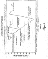
- FIGURE 1 shows a stop/start cycle 50 according to one example of a known stop/start method. Specifically, FIGURE 1 shows a plot of engine speed versus time during an exemplary stop/start cycle 50 of the stop/start method.
- the engine is stopped if stop enablement conditions are met. In the illustrated embodiment, the following stop enablement conditions must be met before a stop/start cycle is initiated:
- the operator input can be pressing the clutch, pressing the accelerator, or rotating the steering wheel slightly.
- the automatic start portion of the stop/start cycle starts the engine in a normal manner, i.e., engaging a starter motor with the engine to turn the engine, activating the fuel injection system, and sequentially providing a spark to each cylinder to ignite the air/fuel mixture in that cylinder (for engines that utilize spark plugs).
- FIGURE 2 a schematic diagram of a vehicle 100 with a representative embodiment of a stop/start system 102 according to the present disclosure is shown.
- the vehicle 100 includes an engine 110, which in the illustrated embodiment is a diesel engine for a heavy duty truck; however, it will be appreciated that the disclosed system is not limited to heavy duty trucks or diesel engines.
- the vehicle can be any type of vehicle, and the engine can be any internal combustion engine.
- the engine 110 includes fuel injectors 116 to provide fuel to the engine cylinders during operation.
- the engine further includes a variety of sensors, including a coolant temperature sensor 132 for sensing the temperature of the engine coolant, an engine speed sensor 130 for sensing engine speed, and a battery status sensor 142 for sensing the charge of the battery.
- the system 102 includes sensors and switches to sense and control various other operational characteristics of the vehicle 100. As shown in FIGURE 2 , the system 102 further include a stop/start switch 160 to allow an operator to engage or disengage the system 120, a vehicle speed sensor 134, an accelerator sensor 136, a brake pedal sensor 138, a steering wheel position sensor 140, and an ignition switch 150.
- the engine 110 can further include a decompression device 114.
- the decompression device 114 is selectively activated to decompress the cylinders of the engine 110 by opening the intake or exhaust valve for each cylinder. Such devices are known and are typically used during startup to reduce the load on the starter 112. With the decompression device 114 activated, instead of compressing air within the cylinders, the pistons reciprocating within the cylinders move air in and out of the cylinders through the open valves. In this manner, the decompression device 114 reduces the resistance on the reciprocating cylinders, thereby reducing the load on the starter during engine startup. With the decompression device 114 deactivated, the valves open and close according normal engine operating timing.
- the illustrated engine 110 includes a decompression device 114, it is contemplated the embodiments of the disclosed stop/start system 102 can also be utilized on engines that do not include a decompression device, and such variations should be considered within the scope of the present disclosure.
- a decompression device it takes approximately 4 seconds for the engine to come to a complete stop.
- engines that do no utilize a decompression device stop much more quickly due to the resistance provided by the gases in the cylinders.
- the vehicle 110 further includes a starter 112 that is configured to selectively engage the engine 110 during the engine startup.
- the starter 112 is a known starter that turns the engine 110 during startup to bring the engine to an operating speed, after which the starter disengages from the engine.
- the vehicle 100 has an engine control module 120 (ECM) 120 that controls various aspects of the engine (fuel delivery, etc.).
- the ECM 120 may include a processor, a memory, an I/O interface suitably interconnected via one or more buses, including but not limited to a Controller Area Network (CAN) bus.
- the memory may include read only memory (ROM), such as programmable ROM (PROM), an erasable programmable ROM (EPROM), and an electrically erasable PROM (EEPROM), etc., random access memory (RAM), and storage memory, such as a solid state hard drive, flash memory, etc.
- ROM read only memory
- PROM programmable ROM
- EPROM erasable programmable ROM
- EEPROM electrically erasable PROM
- RAM random access memory
- storage memory such as a solid state hard drive, flash memory, etc.
- processor is not limited to integrated circuits referred to in the art as a computer, but broadly refers to a microcontroller, a microcomputer, a microprocessor, a programmable logic controller, an application specific integrated circuit, and other programmable circuits, among others.
- ECM 120 engine control module 120
- the ECM 120 receives signals from the engine speed sensor 130 and the coolant temperature sensor 132 regarding the engine speed and coolant temperature, respectively.
- the ECM 120 is also in communication with the starter 112, the decompression device 114 and the fuel injectors 116 in order to affect these control the operation of these and other components.
- the ECM 120 may receive data from other sensors (not shown) indicative of engine operating parameters, etc., in order to affect appropriate timing and duration of fuel delivery, valve actuation, etc.
- the ECM 120 may also receive data generated directly or indirectly from operator inputs.
- FIGURE 3 shows a first exemplary stop/start cycle 60 and a second exemplary stop/start cycle 70 that can result from the presently disclosed stop/start method 200. More specifically, FIGURE 3 shows a plot of engine speed vs. time during the first stop/start cycle 60, in which an intermittent restart is initiated, and a second stop start cycle 70, in which an intermittent restart is requested but restart is delay.
- stop enablement conditions are exemplary, and various other conditions and combinations of conditions may be utilized. In this respect, the described conditions are should not be considered limiting.
- the automatic stop is activated.
- the ECM 120 controls the engine 102 to stop fuel delivery to cylinders via the fuel injectors 116. This can be accomplished by shutting off the fuel pump, closing a valve between the fuel pump and the fuel injectors, or any other suitable means.
- the ignition preferably stays on during the automatic stop; however, it embodiments are contemplated in which the ignition is turned off upon shutdown and turned on during restart.
- the automatic stop also includes activating the decompression device 114. With the decompression device activated, the inlet or exhaust valves on the cylinders are open, and load on the engine is reduced significantly. As a result, engine vibration during shutdown is reduced.
- intermittent restart is a restart requested and initiated before the engine has come to a complete stop, i.e., when V eng > 0.
- an intermittent restart is initiated when an engine restart is requested while the engine speed is still greater than a predetermined threshold.
- the predetermined threshold is approximately 300 rpm, however it will be appreciated that the threshold can be higher or lower than the illustrated embodiment, and systems employing different thresholds should be considered within the scope of the present disclosure.
- the engine restart is requested when the engine speed is above the threshold value.
- the engine restart request is initiated by the driver.
- the request can be initiated by turning the steering wheel slightly, pressing the clutch, pressing the brake pedal, or by any other suitable action performed by the operator.
- the request can also be initiated by two or more of these actions being performed simultaneously or in a particular sequence.
- One of ordinary skill in the art will appreciate that any number of different operator actions can be incorporated to signal a restart request.
- the decompression device 102 Upon initiation of the intermittent restart, the decompression device 102 is deactivated. As a result, the intake and exhaust valves open and close according to the normal engine operating sequence.
- the ECM 120 controls the engine 102 to restart fuel delivery to cylinders via the fuel injectors 116. For a diesel engine, the heat of compression in the cylinders ignites the fuel delivered to the cylinder, the engine 102 restarts, and normal vehicle operation resumes. It will be appreciated that for gasoline powered engines, the intermittent restart may also include restarting a sparking sequence to initiate combustion in the cylinders.
- the engine restart is requested while the engine is still rotating, but is below the threshold speed, i.e. V threshold > V eng > 0. Because the engine speed is too low to restart the engine without the use of a starter, the automatic start sequence restarts the engine according to a normal start sequence.
- the decompression device 114 is activated (or remains activated).
- the starter 112 engages the engine and turns the engine 110 to a start speed. With the engine 110 turning at a start speed, the decompression device 114 is deactivated so that the intake and exhaust valves open and close according to the normal engine operating sequence.
- the ECM 120 also controls the engine 110 to restart fuel delivery to cylinders via the fuel injectors 116. As previously noted, the ignition remains on throughout the stop/start cycle. As a result, upon deactivation of the decompression device 114 and restarting of the fuel delivery to the engine 110, the engine starts, and the starter 112 disengages from the engine.
- V threshold engine threshold speed
- the starter 112 is not utilized for an automatic start sequence
- the starter is utilized for an automatic start sequence
- V threshold engine threshold speed
- alternate embodiments are possible in which two engine threshold speeds are utilized.
- one alternate embodiment of a stop/start system may have an upper engine threshold speed and a lower engine threshold speed.
- the upper engine threshold speed is similar to the previously described single threshold, above which the starter 112 is not utilized during an automatic start sequence.
- the lower engine threshold speed is an engine speed above which the starter is not utilized for an automatic start sequence, nor is simply providing fuel to the engine sufficient to restart the engine. Below the lower engine threshold speed, the starter is utilized during an automatic start sequence.
- an automatic restart is not initiated. Instead, the system waits for the engine speed to drop below the lower engine threshold speed and then initiations an automatic restart sequence using the starter.
- the use of two thresholds allows for a the starter to be engaged at a lower engine speed than that at which the engine cannot be restarted without the use of a starter. This prevents the starter from being engaged in the "death zone," i.e., when the engine speed is higher than a speed at which the starter can be utilized without putting undue wear on the vehicle's drivetrain.
- the lower engine threshold speed can be 0 rpm, i.e., if the engine speed is below the upper engine threshold speed the starter 112 is not utilized for an automatic start sequence. If the engine speed is below the upper engine threshold speed, but the engine has not come to a complete stop, the automatic restart sequence will not begin until the engine stops.
- Such an embodiment is an improvement over known systems in that there is a time after an automatic stop is initiated that a restart is still possible before the engine comes to a complete stop.
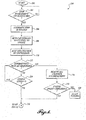
- the method 200 starts at block 202 and proceeds to block 204, in which it is determined whether or the enablement conditions of automatic stop have been met. If the enablement conditions have not been met, the method 200 waits until the enablement conditions have been met. When the enablement conditions of the automatic stop have been met, the method 200 proceeds to block 206, and the automatic stop is activated.
- the method 200 next proceeds to block 212, and it is determined whether an intermittent restart is requested. If an intermittent restart is not requested, the method proceeds to block 214, wherein the engine speed is checked. If the engine speed is greater than 0, then the method 200 returns to block 212. If the engine speed is not > 0, then the method proceeds through block 222 and block 302 ( FIGURE 5 ) to block 304.
- the method 200 moves to block 216.
- the decompression device is deactivated, and the valves operate according to a normal engine operating sequence.
- the method 200 next proceeds to block 218, wherein engine speed is compared to the threshold value. If the engine speed is greater than the threshold value, then the method 200 proceeds to block 220. In block 220, fueling is enabled, and the engine restarts. If the engine speed is less than the threshold value then the method 200 proceeds through block 222 and block 302 ( FIGURE 5 ) to block 304.
- the method 200 remains at block 304 until the restart enablement conditions are met.
- the method 200 moves to block 306, and the automatic start is activated.
- the method 200 proceeds to block 308, in which the decompression device is activated, and then to block 310, in which the starter engages the engine to rotate the engine to a start speed.
- the decompression device is deactivated in block 312, and then in block 314, fuel is delivered to the engine.
- block 318 it is determined whether the engine cranking time has reached a predetermined limit. If the limit has been reached, the method 200 proceeds to block 320, and the starter is disengaged from the engine and turned off. If the limit has not been reached, then the method 200 continues to block 322 and the engine cranking continues.
- the method 200 proceeds to block 324, in which it is determined if the engine is started. If the engine has not started, the method 200 returns to block 316 to continue the engine startup. If the engine has started, the method 200 moves to block 326, where the starter disengages the engine and is turned off. With the engine started and the starter turned off, the method 200 proceeds to block 328 and ends.
Landscapes
- Engineering & Computer Science (AREA)
- Mechanical Engineering (AREA)
- General Engineering & Computer Science (AREA)
- Chemical & Material Sciences (AREA)
- Combustion & Propulsion (AREA)
- Control Of Vehicle Engines Or Engines For Specific Uses (AREA)
- Output Control And Ontrol Of Special Type Engine (AREA)
Applications Claiming Priority (1)
| Application Number | Priority Date | Filing Date | Title |
|---|---|---|---|
| US15/341,320 US9957941B1 (en) | 2016-11-02 | 2016-11-02 | Intermittent restart for automatic engine stop start system |
Publications (2)
| Publication Number | Publication Date |
|---|---|
| EP3318748A2 true EP3318748A2 (de) | 2018-05-09 |
| EP3318748A3 EP3318748A3 (de) | 2018-06-27 |
Family
ID=60201423
Family Applications (1)
| Application Number | Title | Priority Date | Filing Date |
|---|---|---|---|
| EP17199329.8A Withdrawn EP3318748A3 (de) | 2016-11-02 | 2017-10-31 | Intermittierender neustart für ein automatisches motorstopp-/-startsystem |
Country Status (2)
| Country | Link |
|---|---|
| US (1) | US9957941B1 (de) |
| EP (1) | EP3318748A3 (de) |
Cited By (1)
| Publication number | Priority date | Publication date | Assignee | Title |
|---|---|---|---|---|
| EP4311920A3 (de) * | 2022-07-25 | 2024-03-20 | J.C. Bamford Excavators Limited | Wärmeverwaltungssystem |
Families Citing this family (7)
| Publication number | Priority date | Publication date | Assignee | Title |
|---|---|---|---|---|
| US10451022B2 (en) | 2016-11-02 | 2019-10-22 | Paccar Inc | Intermittent restart for automatic engine stop start system |
| JP6642459B2 (ja) * | 2017-01-13 | 2020-02-05 | トヨタ自動車株式会社 | 車両の制御装置 |
| US10690103B2 (en) | 2017-09-26 | 2020-06-23 | Paccar Inc | Systems and methods for using an electric motor in predictive and automatic engine stop-start systems |
| US10487762B2 (en) | 2017-09-26 | 2019-11-26 | Paccar Inc | Systems and methods for predictive and automatic engine stop-start control |
| US10746255B2 (en) | 2018-05-09 | 2020-08-18 | Paccar Inc | Systems and methods for reducing noise, vibration, and/or harshness during engine shutdown and restart |
| US10883566B2 (en) | 2018-05-09 | 2021-01-05 | Paccar Inc | Systems and methods for reducing noise, vibration and/or harshness associated with cylinder deactivation in internal combustion engines |
| JP7492325B2 (ja) * | 2019-11-05 | 2024-05-29 | 株式会社Subaru | エンジンシステム |
Citations (1)
| Publication number | Priority date | Publication date | Assignee | Title |
|---|---|---|---|---|
| WO2016014396A1 (en) | 2014-07-21 | 2016-01-28 | Cummins, Inc. | Smart automatic engine start-stop systems and methods |
Family Cites Families (10)
| Publication number | Priority date | Publication date | Assignee | Title |
|---|---|---|---|---|
| JP3788736B2 (ja) | 2000-12-18 | 2006-06-21 | スズキ株式会社 | エンジンの自動停止始動制御装置 |
| DE102009006664A1 (de) * | 2009-01-29 | 2010-09-02 | Dr.Ing.H.C.F.Porsche Aktiengesellschaft | Verfahren zum Starten einer Brennkraftmaschine |
| JP5149846B2 (ja) | 2009-03-19 | 2013-02-20 | 株式会社デンソー | 内燃機関の自動停止始動制御装置 |
| JP2010242621A (ja) * | 2009-04-06 | 2010-10-28 | Denso Corp | 内燃機関の自動停止始動制御装置 |
| JP5278753B2 (ja) | 2009-04-15 | 2013-09-04 | トヨタ自動車株式会社 | 内燃機関の自動停止始動制御装置 |
| JP5563958B2 (ja) * | 2010-11-12 | 2014-07-30 | 株式会社デンソー | エンジン自動停止始動制御装置 |
| EP2696053B1 (de) * | 2011-04-08 | 2018-01-17 | Toyota Jidosha Kabushiki Kaisha | Steuerungseinrichtung für eine brennkraftmaschine mit kompressor |
| JP5052684B1 (ja) * | 2011-05-17 | 2012-10-17 | 三菱電機株式会社 | エンジン自動停止再始動装置 |
| EP2578871B1 (de) * | 2011-10-03 | 2016-09-21 | C.R.F. Società Consortile per Azioni | Verfahren zur Steuerung einer Brennkraftmaschine mit einem variablen Einlassventilsystem. |
| JP6250484B2 (ja) * | 2014-06-20 | 2017-12-20 | 日立オートモティブシステムズ株式会社 | 内燃機関の自動停止/再始動制御システム及び可変動弁装置 |
-
2016
- 2016-11-02 US US15/341,320 patent/US9957941B1/en active Active
-
2017
- 2017-10-31 EP EP17199329.8A patent/EP3318748A3/de not_active Withdrawn
Patent Citations (1)
| Publication number | Priority date | Publication date | Assignee | Title |
|---|---|---|---|---|
| WO2016014396A1 (en) | 2014-07-21 | 2016-01-28 | Cummins, Inc. | Smart automatic engine start-stop systems and methods |
Cited By (2)
| Publication number | Priority date | Publication date | Assignee | Title |
|---|---|---|---|---|
| EP4311920A3 (de) * | 2022-07-25 | 2024-03-20 | J.C. Bamford Excavators Limited | Wärmeverwaltungssystem |
| US12359637B2 (en) | 2022-07-25 | 2025-07-15 | J.C. Bamford Excavators Limited | Thermal management system |
Also Published As
| Publication number | Publication date |
|---|---|
| EP3318748A3 (de) | 2018-06-27 |
| US9957941B1 (en) | 2018-05-01 |
| US20180119662A1 (en) | 2018-05-03 |
Similar Documents
| Publication | Publication Date | Title |
|---|---|---|
| US11421640B2 (en) | Intermittent restart for automatic engine stop start system | |
| US9957941B1 (en) | Intermittent restart for automatic engine stop start system | |
| JP4200987B2 (ja) | エンジンのアイドルストップ制御装置 | |
| JP2004197719A (ja) | エンジン始動装置 | |
| JP2012140895A (ja) | 車両の制御装置 | |
| CN113217209A (zh) | 用于怠速-停止后发动机起动的方法和系统 | |
| US9599088B2 (en) | System for cranking internal combustion engine by engagement of pinion with ring gear | |
| CN104213991B (zh) | 引擎控制单元 | |
| US20140350826A1 (en) | Engine start control system for vehicle with isg and method thereof | |
| JP2020118058A (ja) | 内燃機関の制御装置 | |
| JP6004810B2 (ja) | 制御装置 | |
| JP2013083185A (ja) | 内燃機関、及び内燃機関のピストン停止位置制御方法 | |
| JP2018145805A (ja) | 車両の制御装置 | |
| CN101205847B (zh) | 内燃机的运行方法和装置 | |
| JP2017110605A (ja) | 車両の制御装置 | |
| JP6877935B2 (ja) | エンジン制御装置 | |
| GB2511601A (en) | A starting method for a combustion engine of a motor vehicle | |
| JP2015048723A (ja) | 内燃機関の制御装置 | |
| JP6188346B2 (ja) | 内燃機関の制御装置 | |
| CN112228263B (zh) | 怠速启停系统和怠速启停的控制方法 | |
| JP6736207B2 (ja) | 内燃機関の制御装置 | |
| JP7218054B2 (ja) | 内燃機関の制御装置 | |
| JP2016113909A (ja) | 内燃機関の制御装置 | |
| JP2019060298A (ja) | 車両制御装置 | |
| JP2017020404A (ja) | エンジン始動制御装置 |
Legal Events
| Date | Code | Title | Description |
|---|---|---|---|
| PUAI | Public reference made under article 153(3) epc to a published international application that has entered the european phase |
Free format text: ORIGINAL CODE: 0009012 |
|
| STAA | Information on the status of an ep patent application or granted ep patent |
Free format text: STATUS: THE APPLICATION HAS BEEN PUBLISHED |
|
| AK | Designated contracting states |
Kind code of ref document: A2 Designated state(s): AL AT BE BG CH CY CZ DE DK EE ES FI FR GB GR HR HU IE IS IT LI LT LU LV MC MK MT NL NO PL PT RO RS SE SI SK SM TR |
|
| AX | Request for extension of the european patent |
Extension state: BA ME |
|
| PUAL | Search report despatched |
Free format text: ORIGINAL CODE: 0009013 |
|
| AK | Designated contracting states |
Kind code of ref document: A3 Designated state(s): AL AT BE BG CH CY CZ DE DK EE ES FI FR GB GR HR HU IE IS IT LI LT LU LV MC MK MT NL NO PL PT RO RS SE SI SK SM TR |
|
| AX | Request for extension of the european patent |
Extension state: BA ME |
|
| RIC1 | Information provided on ipc code assigned before grant |
Ipc: F02D 41/00 20060101ALN20180518BHEP Ipc: F02N 19/00 20100101ALI20180518BHEP Ipc: F02D 41/04 20060101ALI20180518BHEP Ipc: F02D 41/12 20060101ALI20180518BHEP Ipc: F02N 11/08 20060101AFI20180518BHEP Ipc: F01L 13/06 20060101ALI20180518BHEP |
|
| STAA | Information on the status of an ep patent application or granted ep patent |
Free format text: STATUS: REQUEST FOR EXAMINATION WAS MADE |
|
| 17P | Request for examination filed |
Effective date: 20181227 |
|
| RBV | Designated contracting states (corrected) |
Designated state(s): AL AT BE BG CH CY CZ DE DK EE ES FI FR GB GR HR HU IE IS IT LI LT LU LV MC MK MT NL NO PL PT RO RS SE SI SK SM TR |
|
| STAA | Information on the status of an ep patent application or granted ep patent |
Free format text: STATUS: THE APPLICATION IS DEEMED TO BE WITHDRAWN |
|
| 18D | Application deemed to be withdrawn |
Effective date: 20190103 |