EP3318861A2 - Capteur de pression d'orifice rempli de gel pour scellement multimédia robuste - Google Patents
Capteur de pression d'orifice rempli de gel pour scellement multimédia robuste Download PDFInfo
- Publication number
- EP3318861A2 EP3318861A2 EP17195307.8A EP17195307A EP3318861A2 EP 3318861 A2 EP3318861 A2 EP 3318861A2 EP 17195307 A EP17195307 A EP 17195307A EP 3318861 A2 EP3318861 A2 EP 3318861A2
- Authority
- EP
- European Patent Office
- Prior art keywords
- pressure
- isolation layer
- pressure sensor
- sensor
- media isolation
- Prior art date
- Legal status (The legal status is an assumption and is not a legal conclusion. Google has not performed a legal analysis and makes no representation as to the accuracy of the status listed.)
- Ceased
Links
- 238000007789 sealing Methods 0.000 title description 5
- 238000002955 isolation Methods 0.000 claims abstract description 112
- 239000000463 material Substances 0.000 claims abstract description 28
- 238000000034 method Methods 0.000 claims abstract description 24
- 238000012546 transfer Methods 0.000 claims abstract description 8
- 239000000853 adhesive Substances 0.000 claims description 31
- 230000001070 adhesive effect Effects 0.000 claims description 31
- 239000012530 fluid Substances 0.000 claims description 30
- 239000004033 plastic Substances 0.000 claims description 6
- 238000004891 communication Methods 0.000 claims description 4
- 229910052751 metal Inorganic materials 0.000 claims description 4
- 239000002184 metal Substances 0.000 claims description 4
- 238000003825 pressing Methods 0.000 claims description 3
- 239000010410 layer Substances 0.000 description 94
- LVROLHVSYNLFBE-UHFFFAOYSA-N 2,3,6-trichlorobiphenyl Chemical compound ClC1=CC=C(Cl)C(C=2C=CC=CC=2)=C1Cl LVROLHVSYNLFBE-UHFFFAOYSA-N 0.000 description 63
- VYPSYNLAJGMNEJ-UHFFFAOYSA-N Silicium dioxide Chemical compound O=[Si]=O VYPSYNLAJGMNEJ-UHFFFAOYSA-N 0.000 description 4
- 239000000919 ceramic Substances 0.000 description 3
- 230000007613 environmental effect Effects 0.000 description 3
- 239000003822 epoxy resin Substances 0.000 description 3
- 239000004615 ingredient Substances 0.000 description 3
- 229920000647 polyepoxide Polymers 0.000 description 3
- 230000008569 process Effects 0.000 description 3
- 239000012790 adhesive layer Substances 0.000 description 2
- XAGFODPZIPBFFR-UHFFFAOYSA-N aluminium Chemical compound [Al] XAGFODPZIPBFFR-UHFFFAOYSA-N 0.000 description 2
- IISBACLAFKSPIT-UHFFFAOYSA-N bisphenol A Chemical compound C=1C=C(O)C=CC=1C(C)(C)C1=CC=C(O)C=C1 IISBACLAFKSPIT-UHFFFAOYSA-N 0.000 description 2
- 239000003795 chemical substances by application Substances 0.000 description 2
- 230000006835 compression Effects 0.000 description 2
- 238000007906 compression Methods 0.000 description 2
- 230000005684 electric field Effects 0.000 description 2
- 238000005516 engineering process Methods 0.000 description 2
- 229920006332 epoxy adhesive Polymers 0.000 description 2
- 238000004519 manufacturing process Methods 0.000 description 2
- 238000012986 modification Methods 0.000 description 2
- 230000004048 modification Effects 0.000 description 2
- 238000012545 processing Methods 0.000 description 2
- 239000000126 substance Substances 0.000 description 2
- CTFKOMUXSHQLLL-UHFFFAOYSA-N 2,6-ditert-butyl-4-[[1-(hydroxymethyl)cyclopentyl]methyl]phenol Chemical compound CC(C)(C)C1=C(O)C(C(C)(C)C)=CC(CC2(CO)CCCC2)=C1 CTFKOMUXSHQLLL-UHFFFAOYSA-N 0.000 description 1
- RZVHIXYEVGDQDX-UHFFFAOYSA-N 9,10-anthraquinone Chemical compound C1=CC=C2C(=O)C3=CC=CC=C3C(=O)C2=C1 RZVHIXYEVGDQDX-UHFFFAOYSA-N 0.000 description 1
- 229910001369 Brass Inorganic materials 0.000 description 1
- RYGMFSIKBFXOCR-UHFFFAOYSA-N Copper Chemical compound [Cu] RYGMFSIKBFXOCR-UHFFFAOYSA-N 0.000 description 1
- 239000004593 Epoxy Substances 0.000 description 1
- ISWSIDIOOBJBQZ-UHFFFAOYSA-N Phenol Chemical compound OC1=CC=CC=C1 ISWSIDIOOBJBQZ-UHFFFAOYSA-N 0.000 description 1
- 230000004075 alteration Effects 0.000 description 1
- 229910052782 aluminium Inorganic materials 0.000 description 1
- 150000001408 amides Chemical class 0.000 description 1
- 229910021486 amorphous silicon dioxide Inorganic materials 0.000 description 1
- 230000000712 assembly Effects 0.000 description 1
- 238000000429 assembly Methods 0.000 description 1
- 230000004888 barrier function Effects 0.000 description 1
- 229940106691 bisphenol a Drugs 0.000 description 1
- 238000005422 blasting Methods 0.000 description 1
- 230000000903 blocking effect Effects 0.000 description 1
- 239000010951 brass Substances 0.000 description 1
- 239000006229 carbon black Substances 0.000 description 1
- 238000012512 characterization method Methods 0.000 description 1
- 238000002485 combustion reaction Methods 0.000 description 1
- 229910052802 copper Inorganic materials 0.000 description 1
- 239000010949 copper Substances 0.000 description 1
- 238000011161 development Methods 0.000 description 1
- ZBCBWPMODOFKDW-UHFFFAOYSA-N diethanolamine Chemical compound OCCNCCO ZBCBWPMODOFKDW-UHFFFAOYSA-N 0.000 description 1
- GYZLOYUZLJXAJU-UHFFFAOYSA-N diglycidyl ether Chemical compound C1OC1COCC1CO1 GYZLOYUZLJXAJU-UHFFFAOYSA-N 0.000 description 1
- KPUWHANPEXNPJT-UHFFFAOYSA-N disiloxane Chemical class [SiH3]O[SiH3] KPUWHANPEXNPJT-UHFFFAOYSA-N 0.000 description 1
- 239000000314 lubricant Substances 0.000 description 1
- 238000003754 machining Methods 0.000 description 1
- 239000007769 metal material Substances 0.000 description 1
- 238000012544 monitoring process Methods 0.000 description 1
- SLCVBVWXLSEKPL-UHFFFAOYSA-N neopentyl glycol Chemical compound OCC(C)(C)CO SLCVBVWXLSEKPL-UHFFFAOYSA-N 0.000 description 1
- TWNQGVIAIRXVLR-UHFFFAOYSA-N oxo(oxoalumanyloxy)alumane Chemical compound O=[Al]O[Al]=O TWNQGVIAIRXVLR-UHFFFAOYSA-N 0.000 description 1
- 238000011160 research Methods 0.000 description 1
- 239000000377 silicon dioxide Substances 0.000 description 1
- 235000012239 silicon dioxide Nutrition 0.000 description 1
- 229910000679 solder Inorganic materials 0.000 description 1
- 229910001220 stainless steel Inorganic materials 0.000 description 1
- 239000010935 stainless steel Substances 0.000 description 1
- 238000006467 substitution reaction Methods 0.000 description 1
- 238000012360 testing method Methods 0.000 description 1
- XLYOFNOQVPJJNP-UHFFFAOYSA-N water Substances O XLYOFNOQVPJJNP-UHFFFAOYSA-N 0.000 description 1
- 238000003466 welding Methods 0.000 description 1
Images



Classifications
-
- G—PHYSICS
- G01—MEASURING; TESTING
- G01L—MEASURING FORCE, STRESS, TORQUE, WORK, MECHANICAL POWER, MECHANICAL EFFICIENCY, OR FLUID PRESSURE
- G01L19/00—Details of, or accessories for, apparatus for measuring steady or quasi-steady pressure of a fluent medium insofar as such details or accessories are not special to particular types of pressure gauges
- G01L19/06—Means for preventing overload or deleterious influence of the measured medium on the measuring device or vice versa
- G01L19/0627—Protection against aggressive medium in general
- G01L19/0654—Protection against aggressive medium in general against moisture or humidity
-
- G—PHYSICS
- G01—MEASURING; TESTING
- G01L—MEASURING FORCE, STRESS, TORQUE, WORK, MECHANICAL POWER, MECHANICAL EFFICIENCY, OR FLUID PRESSURE
- G01L19/00—Details of, or accessories for, apparatus for measuring steady or quasi-steady pressure of a fluent medium insofar as such details or accessories are not special to particular types of pressure gauges
- G01L19/06—Means for preventing overload or deleterious influence of the measured medium on the measuring device or vice versa
- G01L19/0627—Protection against aggressive medium in general
-
- G—PHYSICS
- G01—MEASURING; TESTING
- G01L—MEASURING FORCE, STRESS, TORQUE, WORK, MECHANICAL POWER, MECHANICAL EFFICIENCY, OR FLUID PRESSURE
- G01L1/00—Measuring force or stress, in general
- G01L1/005—Measuring force or stress, in general by electrical means and not provided for in G01L1/06 - G01L1/22
-
- G—PHYSICS
- G01—MEASURING; TESTING
- G01L—MEASURING FORCE, STRESS, TORQUE, WORK, MECHANICAL POWER, MECHANICAL EFFICIENCY, OR FLUID PRESSURE
- G01L19/00—Details of, or accessories for, apparatus for measuring steady or quasi-steady pressure of a fluent medium insofar as such details or accessories are not special to particular types of pressure gauges
- G01L19/06—Means for preventing overload or deleterious influence of the measured medium on the measuring device or vice versa
- G01L19/0627—Protection against aggressive medium in general
- G01L19/0645—Protection against aggressive medium in general using isolation membranes, specially adapted for protection
-
- G—PHYSICS
- G01—MEASURING; TESTING
- G01L—MEASURING FORCE, STRESS, TORQUE, WORK, MECHANICAL POWER, MECHANICAL EFFICIENCY, OR FLUID PRESSURE
- G01L19/00—Details of, or accessories for, apparatus for measuring steady or quasi-steady pressure of a fluent medium insofar as such details or accessories are not special to particular types of pressure gauges
- G01L19/14—Housings
- G01L19/142—Multiple part housings
- G01L19/143—Two part housings
-
- G—PHYSICS
- G01—MEASURING; TESTING
- G01L—MEASURING FORCE, STRESS, TORQUE, WORK, MECHANICAL POWER, MECHANICAL EFFICIENCY, OR FLUID PRESSURE
- G01L7/00—Measuring the steady or quasi-steady pressure of a fluid or a fluent solid material by mechanical or fluid pressure-sensitive elements
- G01L7/02—Measuring the steady or quasi-steady pressure of a fluid or a fluent solid material by mechanical or fluid pressure-sensitive elements in the form of elastically-deformable gauges
- G01L7/08—Measuring the steady or quasi-steady pressure of a fluid or a fluent solid material by mechanical or fluid pressure-sensitive elements in the form of elastically-deformable gauges of the flexible-diaphragm type
Definitions
- Sensors are commonly used to sense environmental parameters such as pressure, temperature, humidity, flow, thermal conductivity, gas concentration, light, magnetic fields, electric fields, as well as many other environmental parameters.
- sensors are used in a wide variety of applications including, for example, medical applications, flight control applications, industrial process applications, combustion control applications, weather monitoring applications, water metering applications, as well as many other applications.
- a pressure sensor assembly may comprise a sensor unit having a pressure input port on one side, the sensor unit comprising a printed circuit board; a pressure sensor secured to a side of the printed circuit board; a support secured to the side of the printed circuit board, the support circumferentially surrounding the pressure sensor and defining the pressure input port; and a media isolation layer comprising a first media isolation layer applied adjacent to the pressure sensor, and a second media isolation layer comprising a material different from the first media isolation layer located between the first media isolation layer and the pressure input port, wherein the media isolation layer is configured to transfer a pressure caused by a sense media to the pressure sensor.
- a pressure sensor assembly may comprise a sensor unit having a pressure input port on one side, the sensor unit comprising a printed circuit board; a pressure sensor secured to a side of the printed circuit board; a support secured to the side of the printed circuit board, the support circumferentially surrounding the pressure sensor and defining the pressure input port; and at least one media isolation layer contained by the support, the media isolation layer configured to transfer a pressure caused by a sense media to the pressure sensor.
- a method of sensing pressure may comprise applying pressure to a pressure port of a sensor assembly, the sensor assembly comprising a sensor unit having a pressure input port on one side, the sensor unit comprising a printed circuit board; a pressure sensor secured to a side of the printed circuit board; a support secured to the side of the printed circuit board, the support circumferentially surrounding the pressure sensor and defining the pressure input port; and a media isolation layer comprising a first media isolation layer applied adjacent to the pressure sensor, and a second media isolation layer comprising a material different from the first media isolation layer located between the first media isolation layer and the pressure input port; deflecting at least a portion of the pressure sensor with the applied pressure; measuring the deflection of the pressure sensor; and determining a magnitude of the applied pressure based on the measured deflection of the sensor.
- Embodiments of the disclosure include methods and systems for detecting pressure by a pressure sensor.
- An exemplary pressure sensor may comprise a sensor unit comprising a support and one or more media isolation layers located within the support. The support and media isolation layers may be positioned adjacent to a sensor element of the sensor unit.
- Typical pressure sensors may employ one or more O-rings to seal sense media from the sensor.
- harsh or abrasive media may not be sealed well by an O-ring over a long use-life.
- a variety of O-rings may be needed for different types of sense media, and therefore the variety of O-rings should be stocked in a factory, increasing inventory.
- Embodiments of the disclosure may comprise sensor units comprising minimal sealing solutions configured to provide a seal for a wide variety of sense media applications.
- sealing solutions may comprise epoxy adhesives and/or welding methods.
- a support (which may be a metal and/or plastic ring) may provide sealing via the adhesive for a variety of sense media.
- a sensor may be attached to a printed circuit board (PCB) with a support filled with a first media isolation layer (which may comprise a soft gel). Additionally, to provide increased media resistance, a second media isolation layer (of gel) can be applied over the first media isolation layer (wherein the second media isolation layer may provide chemical resistance, abrasive resistance, or another type of resistance). For example, a diesel or lubricant media may be sealed by using a corresponding gel, such as fluorosilicone material.
- a corresponding gel such as fluorosilicone material.
- a sensor assembly 10 may include a sensor unit 20 having a first side 20a and a second side 20b, a pressure port 110 on the first side 20a of the sensor unit 20, and an electrical connector 120 on the second side 20b of the sensor unit 20, as best depicted in Figures 1-7 .
- pressure port 110 may be mechanically connected to sensor unit 20.
- electrical connector 120 may be mechanically and electrically connected to sensor unit 20, and at a second end 120b, the electrical connector 120 may mechanically and electrically connect to a cable harness or other device (not shown) that is configured to receive an output of the sensor unit 20.
- sensor assembly 10 may be any suitable type of sensor assembly.
- sensor assembly 10 may be a pressure sensor assembly, a humidity sensor assembly, a force sensor assembly, a pressure switch assembly, a light sensor assembly, a gas concentration sensor assembly, a magnetic or electrical field sensor assembly, a conductivity sensor assembly, or another other suitable sensor assembly.
- Figures 2 and 3 depict a first end 10a and a second end 10b of the sensor assembly 10.
- the first end 10a of the sensor assembly 10 may be configured to be mechanically connectable to a device having a media to be measured.
- the second end 10b of the sensor assembly 10 may be configured to be mechanically and electrically connected to a device configured to receive an output of the sensor unit 20.
- the pressure port 110 of the sensor assembly 10 may at least partially define a fluid path 34 that extends from an external side of the pressure port 110 to an internal side of the pressure port (e.g. to a media isolation layer 39 of the sensor unit 20), where one or more media isolation layers 38, 39 may cover or encase the sensor 22 within a support 50 of the sensor unit 20 (as shown in Figure 4 , for example).
- the support 50 may form a pressure input port 55 of the sensor unit 20, allowing the fluid path 34 to apply pressure to the media isolation layers 38, 39 and therefore the sensor 22.
- the pressure port 110 may include threads 114 and/or other connecting configuration for mechanically connecting the pressure port 110 and/or the sensor assembly 10 to one or more device having a fluid to be measured.
- pressure port 110 may be depicted as having a male-type connector, the pressure port may be configured with a female-type connector with threads or other connector configuration on an interior surface of the pressure port 110.
- the sensor assembly 10 may also comprise a snubber 35 located within the pressure port 110.
- the snubber 35 can be fitted within the fluid path 34 to protect the sensor unit 20 from large pressure spikes or variations, which may extend the use-life of the sensor unit 20.
- the electrical connector 120 may have an electrical connector body 124 (e.g., a housing) with a first end 124a and a second end 124b, a mechanical connector 130, and one or more electrical terminals 122.
- an electrical connector body 124 e.g., a housing
- the electrical terminals 122 may be exposed at first end 124a of electrical connector body 124
- one or more of the electrical terminals 122 may be exposed at second end 124b of electrical connector body 124.
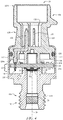
- Figure 4 depicts a cross-section of the sensor assembly 10 taken along line 4-4 in Figure 3 .
- the pressure port 110 may include walls 112 that extend around the sensor unit 20 and the first end 124a of the electrical connector body 124.
- the sensor assembly 10 may include walls and/or a housing separate from the pressure port 110 that may surround and/or mechanically connect to one or more of the electrical connector 120, the sensor unit 20, and the pressure port 110.
- the pressure port 110 and/or the walls 112 may be made out of any material.
- the pressure port 110 and/or the walls 112 may be made out of brass, aluminum, stainless steel, plastic, or any other suitable material.
- at least a portion of the pressure port 110 may have a textured surface or non-textured surface, where the textured surface may facilitate adhering pressure port 110 to another surface and may be formed from one or more processes including, for example, an abrasive etch, grit blasting, a chemical etch, a laser etch, machining, and/or any other suitable texturing technique.
- the support 50 may be secured to or secured relative to an internal side of the pressure port 110 (e.g., to or relative to a shoulder or other portion of the internal side of the pressure port 110) such that the fluid path 34 of the pressure port 110 is in fluid communication with the media isolation layers 38, 39.
- the sensor unit 20 may rest against the pressure port 110, as shown in Figure 4 .
- the pressure port 110 may include an indent or an indent/recess 116, as well as one or more raised portions 118.
- the sensor unit 20 may include a thick film printed ceramic or a printed circuit board (PCB) 24 (e.g., a PCB made, at least in part, of FR4 laminate and/or other material), a sensor 22 (e.g., a pressure sensor with a pressure sense element, or other sensor having a sense element) connected to the PCB, one or more media isolation layers 38, 39, and a support 50.
- the sensor 22 may be back-side mounted on a first side 24a of the PCB 24 and may be configured to perform top-side (of the sense die) sensing.
- top-side sensing may be when a sensed media either directly or indirectly (e.g., through a media isolation layer or other intermediary) interacts with a top-side of a sensor 22, where a back- or bottom-side of the sensor 22 is etched inward toward the top-side to form a sensing diaphragm.
- the media isolation layers 38, 39 may cover or substantially cover the sensor 22 such that media in the fluid path 34 does not directly contact the sensor 22 itself.
- the support 50 may entirely, or at least partially, extend around the media isolation layers 38, 39 and may be connected to the first side 24a of the PCB 24.
- the support 50 may be made from any type of material.
- the support 50 may be made from a plastic, a metal, a ceramic, and/or any other suitable material.
- Back-side mounting the sensor 22 to the first side 24a of the PCB 24 may facilitate creating a robust sensor unit 20, where the first side 24a (e.g., front side) may be facing the fluid path 34.
- back-side mounting the sensor 22 to the first side 24a of the PCB 24 may create a more robust sensor unit 20 because any sensed media acting on the sensor 22 acts to push the sensor 22 against the PCB 24. Additionally, such a configuration may allow for a smaller sensor 22 when compared to sensor units in which a sensor 22 is mounted to a second side of the PCB 24 that faces away from the fluid path.
- Such a smaller sensor 22 may be possible, at least in part, because less sense element surface area is needed to attached the sensor 22 to PCB 24 when the sense element is connected to a first side 24a of the PCB 24 facing the fluid path due to forces from the fluid path 34 pushing the sense element into the PCB 24 instead of pushing the sense element away from the PCB 24.
- the sensor 22 may be described herein as being back-side mounted to the first side 24a of the PCB 24, it is contemplated that the sensor 22 may be mounted relative to the PCB 24 in one or more other configurations.
- the sensor 22 may be mounted to the second side 24b of the PCB 24.
- the sensor 22 may be front side mounted and/or the sensor 22 may be mounted in any other suitable manner.
- the sensor 22 may be electrically connected to PCB 24 in any manner.
- the sensor 22 may be electrically connected to the PCB 24 via wire bonds, bump bonds, and/or in any other suitable manner.
- the sensor 22 When the sensor 22 is configured to sense a pressure in the fluid path 34, the sensor 22 may be arranged to sense an absolute pressure, as shown in Figure 4 , where there may be a vacuum on the back side of the sensor 22 (e.g. between the sensor 22 and the PCB 24).
- the sensor 22 may be configured in the sensor unit 20 as a gage pressure sensor, where a pressure of sensed media in the fluid path 34 is referenced against an atmospheric pressure or other reference pressure.
- the PCB 24 may include an opening extending through the PCB 24 (e.g., extending through the PCB 24 from the first side 24a to the second side 24b of the PCB 24) to allow a reference pressure to reach the back side of the sensor 22.
- Example sensors may include, but are not limited to, those described in U.S. patents: 7,503,221 ; 7,493,822 ; 7,216,547 ; 7,082,835 ; 6,923,069 ; 6,877,380 , and U.S. patent application publications: 2010/0180688 ; 2010/0064818 ; 2007/0095144 ; and 2003/0167851 , all of which are hereby incorporated by reference.
- the media isolation layers 38, 39 may be any type of material configured to transfer a pressure or changes in pressure caused by a sense media in the fluid path 34 to the sensor 22, while providing a barrier between the sensor 22 and the media in the fluid path 34.
- the media isolation layers 38, 39 may be a gel material layer (e.g., a non-compressible material) or other material.
- the sensor 22 and/or the media isolation layers 38, 39 may be surrounded by the support 50.
- the support 50 may be connect to the PCB 24 and provide support to the PCB 24 while maintaining the media isolation layers 38, 39 in a position over the sensor 22.
- the electrical connector 120 and/or the pressure port 110 may mechanically and/or electrically connect to the sensor unit 20.
- the electrical connector body 124 of the electrical connector 120 may abut the second side 24b of the PCB 24.
- the raised portion 118 of the pressure port 110 may abut the first side 24a of the PCB 24 and/or the support 50.
- the electrical connector body 124 may provide support to the PCB 24 against forces produced by the media in the fluid path 34 acting upon the sensor 22 and PCB 24.
- the support from the electrical connector body 124 on the second side 24b of the PCB 24 may align with support on the first side 24a of the PCB 24 from the support 50 and/or raised portion 118 of the pressure port 110, such that the PCB 24 may be sandwiched between the electrical connector body 124 and the support 50 and/or raised portion 118.
- This configuration may help support the PCB 24 and reduce stress at the sensor 22.
- the support acting on the PCB 24 may be sufficient such that a pressure source exerting a pressure of 1, 2, 4, 8, 10, 20, 40, 50, 100, 1000, 2000, 5000 PSI or more on the sensor 22 and/or PCB 24 does not affect the accuracy of the output of the sensor assembly 10, by, for example more than 0.01 percent, 0.1 percent, 1 percent, 5 percent, 10 percent or more, as desired.
- the support applied to the PCB 24 by the electrical connector 120, pressure port 110, and/or the support 50 may be configured or shaped to distribute forces that may be applied to PCB 24 such that the PCB 24 may remain sufficiently flat so as to cause less than a particular percentage error in the output of sensor 22 when a pressure is applied to the sensor 22.
- the particular percentage error may be ten percent (%) or less error in the output of sensor 22, or another desirable limit of error including, but not limited to, less than .001%, 0.01%, 0.1%, 1.0%, 2.0%, 5.0%, 10.0%, or 20.0%.
- the walls 112 of the pressure port 110 may receive the electrical connector 120.
- An O-ring 126 may be received in and/or at the first end 124a of the electrical connector body 124 to create a seal between the electrical connector body 124 and the walls 112 of the pressure port 110.
- the walls 112 of the pressure port may be formed (e.g., bent, crimped, etc.) around the electrical connector body 124 of the electrical connector 120. Such forming of the walls 112 may compress the O-ring 126 to create environmental and pneumatic seals in the sensor assembly 10.
- FIG. 5 is a detailed view of the sensor unit 20.
- the sensor unit 20 may comprise the PCB 24, sensor 22, media isolation layers 38 and 39, and support 50 (as described above).
- the sensor 22 may be directly attached to the PCB 24 via adhesive 56.
- the first media isolation layer 38 may be directly attached to the PCB 24 over the sensor 22.
- the support 50 may also be directly attached to the PCB 24, via one or more layers of adhesive 56.
- the sensor unit 20 may in some embodiments comprise a second media isolation layer 39, which may be applied over the first media isolation layer 38.
- the second media isolation layer 39 may comprise a suitable material for blocking media from entering the sensor unit 20, wherein the second media isolation layer 39 may be chosen based on the application and use of the sensor assembly 10.
- the sensor unit 20 may not comprise an O-ring within the sensor unit 20.
- the absence of an O-ring within the sensor unit 20 may simplify the manufacturing process of the sensor unit 20 (and therefore the sensor assembly 10) and may allow for more precise spacing between the elements of the sensor unit 20 and the sensor assembly 10 as a whole.
- the thickness of the media isolation layers 38 and 39 may be more precisely controlled without an O-ring.
- harsh or abrasive sense media may penetrate the seal with an O-ring, and the O-ring compression may set at higher temperatures, causing leakage over a period of time. Therefore, the media isolation layers 38, 39 and support 50 may be used without an O-ring.
- the support 50 may comprise an opening exposing the second media isolation layer 39 (and/or the first media isolation layer 38) to the fluid path 34.
- the support 50 may be attached to the raised portion 118 of the pressure port 110 using one or more layers of adhesive 54 between the support 50 and a shaped surface 52 of the raised portion 118.
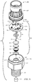
- FIG. 6 is an exploded perspective view of the sensor assembly 10.
- the sensor 22 may include an application specific integrated circuit (ASIC) 40.
- the ASIC 40 may be attached to the first side 24a of the PCB 24.
- the ASIC 40 may be electrically connected to the PCB 24 via wire bonds, bump bonds, electrical terminals, and/or any other suitable electrical connections.
- an attach or adhesive 56 may be used to mechanically and/or electrically connect one or more of the sensor 22, the support 50, and/or the ASIC 40 to the first side 24a of the PCB 24.
- the adhesives 56 and 54 described herein may be a single piece or layer of adhesive, or may include two or more pieces or layers of adhesive.
- Adhesive layer 56 may be any adhesive capable of facilitating assembly of sensor assembly 10, such as an epoxy adhesive or other similar or different adhesives.
- Illustrative example adhesives may include, but are not limited to, an adhesive having the ingredients of at least Bisphenol-A type epoxy resin, Diglycidyl ether of neopentyl glycol, cycloaliphatic/aliphatic amine, aluminum oxide, carbon black, and amorphous silicon dioxide; an adhesive having the ingredients of epoxy phenol novalac (25%-50% by weight), aluminum powder (10%-25% by weight), flexibilizer epoxy resin (10%-25% by weight), curing agent (2.5%-10% by weight), siloxane treated silicon dioxide (2.5%-10% by weight), silicon dioxide, chemically prepared ( ⁇ 2.5% by weight), and curing agent ( ⁇ 2.5% by weight); and an adhesive having the ingredients of epoxy resin (70%-90% by weight), non-volatile amide (10%-30% by weight) and amorphous silica (1%-5% by weight), or other suitable adhesives as desired.
- the support 50 may comprise a metal material, plastic material, [other material examples].
- the support 50 may be configured to form a secure vertical connection with the pressure port 110 via the layer(s) of adhesive 54.
- the adhesive configuration may provide a strong shear adhesive joint, increasing the strength of the sensor assembly 10 to withstand high burst pressures.
- the adhesive layers 54 and 56 may be chosen to withstand variations in temperature and pressure, as well as variations in media entering the pressure port 110.
- the sensor assembly 10 may also comprise the snubber 35 located within the pressure port 110.
- the snubber 35 can be fitted within the fluid path to protect the sensor unit 20 from large pressure spikes or variations, which may extend the use-life of the sensor unit 20.
- the PCB 24 may include one or more processing electronics and/or compensation circuitry connected to or on the second side 24b of the PCB 24, as best shown in Figures 6 and 8 .
- processing electronics may be electrically connected to the sensor 22 and/or electrical terminals 92 to process electrical signals from the sensor 22 and/or to transfer outputs from the sensor 22 to electrical terminals 122 (shown in Figure 4 ) of the electrical connector 120.
- the PCB 24 may include circuitry that may be configured to format the one or more output signals provided by the sensor 22 into a particular output format.
- circuitry of the PCB 24 e.g., circuitry on one or more of the first side 24a and the second side 24b of the PCB 24
- the circuitry of the PCB 24 may be configured to regulate an output voltage.
- Circuitry on the PCB 24 for providing a ratio-metric (or other) output may include traces and/or other circuitry that may serve as a conduit to test pads and/or for providing the ratio-metric (or other) output to electrical connector 120, where the circuitry does not necessarily reformat the output.
- the electrical connector 120 may include one or more connectors 128 (e.g., compliant pins, solder pins (e.g., with a thick film printed ceramic or in other instances), and/or other connectors) configured to mechanically and/or electrically engage the PCB 24.
- Connectors 128 may be connected to the electrical connector body 124 in any manner; for example, connectors 128 may be insert molded in the electrical connector body 124.
- the one or more connectors 128 may include a compliant pin that may be configured to mechanically engage and electrically connect to an electrical terminal 92 of the PCB 24.
- Compliant pins are discussed in greater depth in U.S. Patent No. 7,458,274, issued on December 2, 2008 to Lamb et al. and titled "Pressure Sensor Incorporating a Compliant Pin" which is hereby fully incorporated by reference.
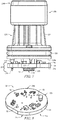
- Figure 7 depicts a view of the sensor unit 20 and the electrical connector 120 (without the pressure port 110 attached to the assembly).
- the PCB 24 of the sensor unit 20 is shown attached to the one or more electrical terminals 122 (via the one or more connectors 128).
- Figure 8 is a perspective view of the PCB 24, showing the second side 24b of the PCB 24.
- the PCB 24 may comprise any number of elements attached to the second side 24b.
- the PCB 24 may comprise electrical terminals 92 configured to receive the connectors 128, to mechanically and electrically connect the electrical connector 120 to the PCB 24.
- the sensor unit 20 may be calibrated and/or compensated prior to further assembly into the sensor assembly 10. Alternatively, or in addition, the sensor unit 20 may be calibrated and/or compensated after assembly into the sensor assembly 10.
- the sensor unit 20 of the sensor assembly 10 may be configured to determine pressure from a sense media, wherein the sense media may enter the pressure port 110 via the fluid path 34.
- the sense media may enter the sensor unit 20 via a pressure input port 55 of the support 50, and the sense media may contact the second media isolation layer 39, thereby compressing the media isolation layer 39 and the first media isolation layer 38.
- the compression of the media isolation layers 38 and 39 may deflect at least a portion (such as a diaphragm or other sense element) of the sensor 22.
- the sensor 22 may be configured to determine a pressure associated with the deflection of the sensor 22.
- the pressure port 110 may be configured to supply the sense media to the sensor unit 20.
- the electrical connector 120 may be configured to electrically connect with the sensor unit 20 to receive the determined pressure from the sensor unit 20.
- the electrical connector 120 may also connect the sensor unit 20 to another device configured to receive the determined pressure.
- the sensor assembly 10 may be assembled in one or more exemplary methods.
- One method begins by providing a PCB 24.
- Adhesive 56 may be applied to the first side 24a of the PCB 24.
- the sensor 22 may be placed on an associated piece of adhesive 56
- the ASIC 40 may be placed on an associated piece of adhesive 56
- the support 50 may be placed on an associated piece of adhesive 56.
- the adhesive(s) 56 may be cured.
- the sensor 22, the ASIC 40, and/or other electronic components may then be wire bonded or otherwise electrically connected to the PCB 24.
- a first media isolation layer 38 may then be applied to the sensor 22 and the PCB 24 through a pressure input port 55 in the support 50, where the support 50 may circumferentially or substantially circumferentially surround the sensor 22 (e.g., in such cases, the support 50 may be a ring or a gel ring supporting the media isolation layer 38 covering the sensor 22).
- the media isolation layer 38 may be cured.
- the media isolation layer 38 may be cured by applying a vacuum and/or applying a specific temperature to the media isolation layer 38.
- a second media isolation layer 39 may be applied over the first media isolation layer 38 through the pressure input port 55 in the support 50, where the support 50 may circumferentially or substantially circumferentially surround the sensor 22 and media isolation layers 38 and 39.
- the media isolation layer 39 may be cured. In some cases, the media isolation layer 39 may be cured by applying a vacuum and/or applying a specific temperature to the media isolation layer 39. In some embodiments, the first media isolation layer 38 and the second media isolation layer 39 may be cured separately. In some embodiments, the first media isolation layer 38 and the second media isolation layer 39 may be cured (at least partially) at the same time. Application and curing of the media isolation layers may form the sensor unit 20. In some cases, the sensor unit 20 may be calibrated over pressure at this stage, although this is not required.
- the electrical connector 120 may be prepped for connection to the sensor unit 20 by loading the O-ring 126 onto the electrical connector body 124.
- the electrical connector 120 may be connected to the sensor unit 20 by placing the connectors 128 into openings of electrical terminals 92 of the PCB 24 to mechanically and electrically connect the electrical connector 120 to the PCB 24.
- the electrical connector 120 and the sensor unit 20 may then be inserted into the pressure port 110.
- the raised portions 118 of the pressure port 110 may be coated with adhesive 54, the support 50 may be placed on the adhesive 54, and the adhesive 54 may be cured.
- the walls 112 may be formed (e.g., bent, crimped, etc.) around the electrical connector 120 to form the sensor assembly 10.
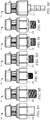
- Figures 9A-9G illustrate exemplary sensor assemblies 10, wherein the pressure port 110 of the sensor assembly 10 may comprise one of many variations in connector type.
- Figure 9A illustrates a 7/16-20 Female Schrader with deflator.
- Figure 9B illustrates a 1/4-18 NPT.
- Figure 9C illustrates a 1/8-27 NPT.
- Figure 9D illustrates a G 1/4 BSPP (ISO 228-1).
- Figure 9E illustrates a M12 X 1.5 (ISO 6149-3).
- Figure 9F illustrates an ISO 1179-2, G 1/4 A - L.
- Figure 9G illustrates a 1 ⁇ 4-inch OD copper tube.
- a pressure sensor assembly may comprise a sensor unit having a pressure input port on one side, the sensor unit comprising a printed circuit board; a pressure sensor secured to a side of the printed circuit board; a support secured to the side of the printed circuit board, the support circumferentially surrounding the pressure sensor and defining the pressure input port; and a media isolation layer comprising a first media isolation layer applied adjacent to the pressure sensor, and a second media isolation layer comprising a material different from the first media isolation layer located between the first media isolation layer and the pressure input port, wherein the media isolation layer is configured to transfer a pressure caused by a sense media to the pressure sensor.
- a second embodiment can include the pressure sensor assembly of the first embodiment, wherein the first media isolation layer comprises a first gel material, and wherein the second media isolation layer comprises a second gel material.
- a third embodiment can include the pressure sensor assembly of the first or second embodiments, wherein the second media isolation layer comprises a chemically resistant gel material.
- a fourth embodiment can include the pressure sensor assembly of any of the first to third embodiments, wherein the media isolation layer is contained by the support.
- a fifth embodiment can include the pressure sensor assembly of any of the first to fourth embodiments, further comprising a pressure port having a fluid path that extends from an external side of the pressure port to the pressure input port, wherein the support is secured relative to the pressure port such that the fluid path of the pressure port is in fluid communication with the media isolation layer.
- a sixth embodiment can include the pressure sensor assembly of the fifth embodiment, wherein the support is secured to a raised portion of the pressure port via adhesive.
- a seventh embodiment can include the pressure sensor assembly of the fifth or sixth embodiments, further comprising a snubber located within the fluid path of the pressure port.
- An eighth embodiment can include the pressure sensor assembly of any of the first to seventh embodiments, further comprising an electrical connector including one or more electrical terminals, wherein at least one of the one or more electrical terminals are electrically connected to an output of the sensor unit.
- a ninth embodiment can include the pressure sensor assembly of any of the first to eighth embodiments, wherein the support comprises a metal ring.
- a tenth embodiment can include the pressure sensor assembly of any of the first to ninth embodiments, wherein the support comprises a plastic ring.
- a pressure sensor assembly may comprise a sensor unit having a pressure input port on one side, the sensor unit comprising a printed circuit board; a pressure sensor secured to a side of the printed circuit board; a support secured to the side of the printed circuit board, the support circumferentially surrounding the pressure sensor and defining the pressure input port; and at least one media isolation layer contained by the support, the media isolation layer configured to transfer a pressure caused by a sense media to the pressure sensor.
- a twelfth embodiment can include the pressure sensor assembly of the eleventh embodiment, wherein the at least one media isolation layer comprises a first media isolation layer applied adjacent to the pressure sensor, and a second media isolation layer comprising a material different from the first media isolation layer located between the first media isolation layer and the pressure input port.
- a thirteenth embodiment can include the pressure sensor assembly of the twelfth embodiment, wherein the second media isolation layer comprises a chemically resistant gel material.
- a fourteenth embodiment can include the pressure sensor assembly of any of the eleventh to thirteenth embodiments, further comprising a pressure port having a fluid path that extends from an external side of the pressure port to the pressure input port, wherein the support is secured relative to the pressure port such that the fluid path of the pressure port is in fluid communication with the at least one media isolation layer.
- a fifteenth embodiment can include the pressure sensor assembly of any of the eleventh to fourteenth embodiments, wherein the circumference of the support is less than the circumference of the printed circuit board.
- a sixteenth embodiment can include the pressure sensor assembly of any of the eleventh to fifteenth embodiments, wherein the support comprises a lip configured to be secured to the printed circuit board via adhesive.
- a seventeenth embodiment can include the pressure sensor assembly of any of the eleventh to sixteenth embodiments, further comprising an electrical connector including one or more electrical terminals, wherein at least one of the one or more electrical terminals are electrically connected to an output of the sensor unit.
- a method of sensing pressure may comprise applying pressure to a pressure port of a sensor assembly, the sensor assembly comprising a sensor unit having a pressure input port on one side, the sensor unit comprising a printed circuit board; a pressure sensor secured to a side of the printed circuit board; a support secured to the side of the printed circuit board, the support circumferentially surrounding the pressure sensor and defining the pressure input port; and a media isolation layer comprising a first media isolation layer applied adjacent to the pressure sensor, and a second media isolation layer comprising a material different from the first media isolation layer located between the first media isolation layer and the pressure input port; deflecting at least a portion of the pressure sensor with the applied pressure; measuring the deflection of the pressure sensor; and determining a magnitude of the applied pressure based on the measured deflection of the sensor.
- a nineteenth embodiment can include the method of the eighteenth embodiment, wherein deflecting at least a portion of the pressure sensor comprises compressing the first media isolation layer and the second media isolation layer.
- a twentieth embodiment can include the method of the eighteenth or nineteenth embodiments, further comprising electrically communicating the determined magnitude of the applied pressure via an electrical connector.
Landscapes
- Physics & Mathematics (AREA)
- General Physics & Mathematics (AREA)
- Measuring Fluid Pressure (AREA)
- Pressure Sensors (AREA)
- Infusion, Injection, And Reservoir Apparatuses (AREA)
Applications Claiming Priority (1)
| Application Number | Priority Date | Filing Date | Title |
|---|---|---|---|
| US15/293,043 US9945747B1 (en) | 2016-10-13 | 2016-10-13 | Gel filled port pressure sensor for robust media sealing |
Publications (2)
| Publication Number | Publication Date |
|---|---|
| EP3318861A2 true EP3318861A2 (fr) | 2018-05-09 |
| EP3318861A3 EP3318861A3 (fr) | 2018-08-29 |
Family
ID=60037516
Family Applications (1)
| Application Number | Title | Priority Date | Filing Date |
|---|---|---|---|
| EP17195307.8A Ceased EP3318861A3 (fr) | 2016-10-13 | 2017-10-06 | Capteur de pression d'orifice rempli de gel pour scellement multimédia robuste |
Country Status (3)
| Country | Link |
|---|---|
| US (1) | US9945747B1 (fr) |
| EP (1) | EP3318861A3 (fr) |
| CN (1) | CN107941382B (fr) |
Cited By (1)
| Publication number | Priority date | Publication date | Assignee | Title |
|---|---|---|---|---|
| WO2018224278A1 (fr) * | 2017-06-08 | 2018-12-13 | Robert Bosch Gmbh | Ensemble capteur de pression micromécanique et procédé de fabrication d'un ensemble capteur de pression micromécanique |
Families Citing this family (13)
| Publication number | Priority date | Publication date | Assignee | Title |
|---|---|---|---|---|
| US10215655B2 (en) * | 2015-12-31 | 2019-02-26 | Honeywell International Inc. | Pressure sensor assembly |
| JP7107051B2 (ja) * | 2017-09-08 | 2022-07-27 | 富士電機株式会社 | 圧力センサ装置 |
| US10890502B2 (en) * | 2017-09-08 | 2021-01-12 | Fuji Electric Co., Ltd. | Pressure sensor device |
| US11105700B2 (en) * | 2018-05-15 | 2021-08-31 | Tyco Electronics Amp Korea Co., Ltd. | Snubber for pressure sensor and pressure sensor comprising the same |
| KR102665303B1 (ko) * | 2018-05-15 | 2024-05-13 | 타이코에이엠피 주식회사 | 압력 센서용 스누버 및 이를 포함하는 압력 센서 |
| DE102018222781A1 (de) * | 2018-12-21 | 2020-06-25 | Robert Bosch Gmbh | Drucksensoranordnung |
| TWI691881B (zh) * | 2019-01-24 | 2020-04-21 | 中光電智能感測股份有限公司 | 力量感測器 |
| US10830653B2 (en) | 2019-03-27 | 2020-11-10 | Honeywell International Inc. | Noninvasive blood pressure sensor |
| CN115426937A (zh) * | 2020-01-17 | 2022-12-02 | My01Ip控股公司 | 包含传感器和顺应结构的植入式传感器组件 |
| US10852166B1 (en) * | 2020-02-20 | 2020-12-01 | Honeywell International Inc. | Pressure sensor with contoured mating face |
| CN113945231A (zh) * | 2020-07-16 | 2022-01-18 | 霍尼韦尔国际公司 | 位置传感器 |
| WO2022137216A1 (fr) * | 2020-12-21 | 2022-06-30 | Padmini Vna Mechatronics Ltd. | Capteur de pression et de température d'urée à étanchéité améliorée |
| US20250085182A1 (en) * | 2023-09-11 | 2025-03-13 | Nxp Usa, Inc. | Low stress packaging for environmental sensors |
Citations (12)
| Publication number | Priority date | Publication date | Assignee | Title |
|---|---|---|---|---|
| JPH0212031A (ja) * | 1988-06-29 | 1990-01-17 | Seiko Epson Corp | 半導体センサユニットの構造 |
| US20030167851A1 (en) | 2002-01-30 | 2003-09-11 | Parker Gregory D. | Absolute micromachined silicon pressure sensor with backside hermetic cover and method of making the same |
| US6877380B2 (en) | 2002-10-01 | 2005-04-12 | Honeywell International Inc. | Diaphragm for bonded element sensor |
| US6923069B1 (en) | 2004-10-18 | 2005-08-02 | Honeywell International Inc. | Top side reference cavity for absolute pressure sensor |
| US7082835B2 (en) | 2003-06-18 | 2006-08-01 | Honeywell International Inc. | Pressure sensor apparatus and method |
| US20070095144A1 (en) | 2005-11-03 | 2007-05-03 | Honeywell International Inc. | Low cost high-pressure sensor |
| US7216547B1 (en) | 2006-01-06 | 2007-05-15 | Honeywell International Inc. | Pressure sensor with silicon frit bonded cap |
| US7458274B2 (en) | 2007-02-20 | 2008-12-02 | Honeywell International Inc. | Pressure sensor incorporating a compliant pin |
| US7493822B2 (en) | 2007-07-05 | 2009-02-24 | Honeywell International Inc. | Small gauge pressure sensor using wafer bonding and electrochemical etch stopping |
| US7503221B2 (en) | 2006-11-08 | 2009-03-17 | Honeywell International Inc. | Dual span absolute pressure sense die |
| US20100064818A1 (en) | 2005-09-27 | 2010-03-18 | Honeywell International Inc. | Method of flip chip mounting pressure sensor dies to substrates and pressure sensors formed thereby |
| US20100180688A1 (en) | 2009-01-21 | 2010-07-22 | Honeywell International Inc. | Media isolated pressure transducer having boss comprising single metal diaphragm |
Family Cites Families (12)
| Publication number | Priority date | Publication date | Assignee | Title |
|---|---|---|---|---|
| DE19637763A1 (de) * | 1996-09-16 | 1998-03-19 | Trw Fahrzeugelektrik | Drucksensoreinheit, insbesondere für die Kraftfahrzeugtechnik |
| US6255728B1 (en) | 1999-01-15 | 2001-07-03 | Maxim Integrated Products, Inc. | Rigid encapsulation package for semiconductor devices |
| JP3498665B2 (ja) * | 1999-03-12 | 2004-02-16 | 株式会社デンソー | 圧力検出装置およびその製造方法 |
| US6550337B1 (en) * | 2000-01-19 | 2003-04-22 | Measurement Specialties, Inc. | Isolation technique for pressure sensing structure |
| US7077008B2 (en) * | 2004-07-02 | 2006-07-18 | Honeywell International Inc. | Differential pressure measurement using backside sensing and a single ASIC |
| JP2006170650A (ja) * | 2004-12-13 | 2006-06-29 | Kawamoto Densan Kk | 圧力センサおよび圧力式水位計 |
| JP2006177859A (ja) * | 2004-12-24 | 2006-07-06 | Denso Corp | 圧力センサ |
| US7210346B1 (en) * | 2005-12-21 | 2007-05-01 | Honeywell International Inc. | Modular sensing apparatus |
| US7647835B2 (en) * | 2007-09-19 | 2010-01-19 | Honeywell International Inc. | Pressure sensor stress isolation pedestal |
| US8215176B2 (en) | 2009-05-27 | 2012-07-10 | Continental Automotive Systems, Inc. | Pressure sensor for harsh media sensing and flexible packaging |
| US8371176B2 (en) * | 2011-01-06 | 2013-02-12 | Honeywell International Inc. | Media isolated pressure sensor |
| US9593995B2 (en) | 2014-02-28 | 2017-03-14 | Measurement Specialties, Inc. | Package for a differential pressure sensing die |
-
2016
- 2016-10-13 US US15/293,043 patent/US9945747B1/en active Active
-
2017
- 2017-10-06 EP EP17195307.8A patent/EP3318861A3/fr not_active Ceased
- 2017-10-12 CN CN201710947198.8A patent/CN107941382B/zh active Active
Patent Citations (12)
| Publication number | Priority date | Publication date | Assignee | Title |
|---|---|---|---|---|
| JPH0212031A (ja) * | 1988-06-29 | 1990-01-17 | Seiko Epson Corp | 半導体センサユニットの構造 |
| US20030167851A1 (en) | 2002-01-30 | 2003-09-11 | Parker Gregory D. | Absolute micromachined silicon pressure sensor with backside hermetic cover and method of making the same |
| US6877380B2 (en) | 2002-10-01 | 2005-04-12 | Honeywell International Inc. | Diaphragm for bonded element sensor |
| US7082835B2 (en) | 2003-06-18 | 2006-08-01 | Honeywell International Inc. | Pressure sensor apparatus and method |
| US6923069B1 (en) | 2004-10-18 | 2005-08-02 | Honeywell International Inc. | Top side reference cavity for absolute pressure sensor |
| US20100064818A1 (en) | 2005-09-27 | 2010-03-18 | Honeywell International Inc. | Method of flip chip mounting pressure sensor dies to substrates and pressure sensors formed thereby |
| US20070095144A1 (en) | 2005-11-03 | 2007-05-03 | Honeywell International Inc. | Low cost high-pressure sensor |
| US7216547B1 (en) | 2006-01-06 | 2007-05-15 | Honeywell International Inc. | Pressure sensor with silicon frit bonded cap |
| US7503221B2 (en) | 2006-11-08 | 2009-03-17 | Honeywell International Inc. | Dual span absolute pressure sense die |
| US7458274B2 (en) | 2007-02-20 | 2008-12-02 | Honeywell International Inc. | Pressure sensor incorporating a compliant pin |
| US7493822B2 (en) | 2007-07-05 | 2009-02-24 | Honeywell International Inc. | Small gauge pressure sensor using wafer bonding and electrochemical etch stopping |
| US20100180688A1 (en) | 2009-01-21 | 2010-07-22 | Honeywell International Inc. | Media isolated pressure transducer having boss comprising single metal diaphragm |
Cited By (2)
| Publication number | Priority date | Publication date | Assignee | Title |
|---|---|---|---|---|
| WO2018224278A1 (fr) * | 2017-06-08 | 2018-12-13 | Robert Bosch Gmbh | Ensemble capteur de pression micromécanique et procédé de fabrication d'un ensemble capteur de pression micromécanique |
| US11397121B2 (en) | 2017-06-08 | 2022-07-26 | Robert Bosch Gmbh | Micromechanical pressure sensor system and method for manufacturing a micromechanical pressure sensor system |
Also Published As
| Publication number | Publication date |
|---|---|
| EP3318861A3 (fr) | 2018-08-29 |
| US9945747B1 (en) | 2018-04-17 |
| CN107941382A (zh) | 2018-04-20 |
| US20180106694A1 (en) | 2018-04-19 |
| CN107941382B (zh) | 2021-04-13 |
Similar Documents
| Publication | Publication Date | Title |
|---|---|---|
| US9945747B1 (en) | Gel filled port pressure sensor for robust media sealing | |
| US10215655B2 (en) | Pressure sensor assembly | |
| US8459125B2 (en) | Pressure sensor assembly | |
| US8934263B2 (en) | Protective cover for pressure sensor assemblies | |
| US8671753B2 (en) | Cable harness for a sensor | |
| US8656786B2 (en) | Interchangeable pressure sensor assembly and methods of assembly | |
| US8817483B2 (en) | Connector assembly for a sensor | |
| JP4550364B2 (ja) | 半導体圧力センサ | |
| EP2554966B1 (fr) | Joint entre un capteur de pression et l'orifice de pression d'un ensemble capteur | |
| US10466125B2 (en) | Pressure sensor sub assembly and fabrication | |
| EP2587241A2 (fr) | Capteur avec joint de support à sécurité intégrée | |
| KR20180013925A (ko) | 유체 매체의 압력 검출 장치, 및 상기 장치의 제조 방법 | |
| WO2009087767A1 (fr) | Capteur de pression et procédé pour sa fabrication | |
| KR101297141B1 (ko) | 압력 센서 및 압력 센서의 부착 구조 | |
| CN105628286B (zh) | 压力传感器 | |
| CN117906824A (zh) | 一种压力传感器 | |
| CN101657709A (zh) | 压力传感器方法和设备 | |
| CN115144124B (zh) | 传感器和阀组件 | |
| CN117906823A (zh) | 一种压力传感器 | |
| JP4622666B2 (ja) | 電子装置 | |
| CN219870100U (zh) | 压力传感器模块和压力测量装置 | |
| CN111279170A (zh) | 压力传感器 |
Legal Events
| Date | Code | Title | Description |
|---|---|---|---|
| PUAI | Public reference made under article 153(3) epc to a published international application that has entered the european phase |
Free format text: ORIGINAL CODE: 0009012 |
|
| STAA | Information on the status of an ep patent application or granted ep patent |
Free format text: STATUS: REQUEST FOR EXAMINATION WAS MADE |
|
| 17P | Request for examination filed |
Effective date: 20171006 |
|
| AK | Designated contracting states |
Kind code of ref document: A2 Designated state(s): AL AT BE BG CH CY CZ DE DK EE ES FI FR GB GR HR HU IE IS IT LI LT LU LV MC MK MT NL NO PL PT RO RS SE SI SK SM TR |
|
| AX | Request for extension of the european patent |
Extension state: BA ME |
|
| PUAL | Search report despatched |
Free format text: ORIGINAL CODE: 0009013 |
|
| AK | Designated contracting states |
Kind code of ref document: A3 Designated state(s): AL AT BE BG CH CY CZ DE DK EE ES FI FR GB GR HR HU IE IS IT LI LT LU LV MC MK MT NL NO PL PT RO RS SE SI SK SM TR |
|
| AX | Request for extension of the european patent |
Extension state: BA ME |
|
| RIC1 | Information provided on ipc code assigned before grant |
Ipc: G01L 19/06 20060101AFI20180724BHEP |
|
| STAA | Information on the status of an ep patent application or granted ep patent |
Free format text: STATUS: EXAMINATION IS IN PROGRESS |
|
| 17Q | First examination report despatched |
Effective date: 20190308 |
|
| STAA | Information on the status of an ep patent application or granted ep patent |
Free format text: STATUS: THE APPLICATION HAS BEEN REFUSED |
|
| 18R | Application refused |
Effective date: 20191130 |