EP3318941B1 - Analyse de machine de système d'automatisation industrielle pour une entreprise connectée - Google Patents
Analyse de machine de système d'automatisation industrielle pour une entreprise connectée Download PDFInfo
- Publication number
- EP3318941B1 EP3318941B1 EP17200073.9A EP17200073A EP3318941B1 EP 3318941 B1 EP3318941 B1 EP 3318941B1 EP 17200073 A EP17200073 A EP 17200073A EP 3318941 B1 EP3318941 B1 EP 3318941B1
- Authority
- EP
- European Patent Office
- Prior art keywords
- machine
- data
- industrial automation
- dashboard
- oem
- Prior art date
- Legal status (The legal status is an assumption and is not a legal conclusion. Google has not performed a legal analysis and makes no representation as to the accuracy of the status listed.)
- Active
Links
Images





Classifications
-
- G—PHYSICS
- G05—CONTROLLING; REGULATING
- G05B—CONTROL OR REGULATING SYSTEMS IN GENERAL; FUNCTIONAL ELEMENTS OF SUCH SYSTEMS; MONITORING OR TESTING ARRANGEMENTS FOR SUCH SYSTEMS OR ELEMENTS
- G05B19/00—Program-control systems
- G05B19/02—Program-control systems electric
- G05B19/418—Total factory control, i.e. centrally controlling a plurality of machines, e.g. direct or distributed numerical control [DNC], flexible manufacturing systems [FMS], integrated manufacturing systems [IMS] or computer integrated manufacturing [CIM]
- G05B19/4185—Total factory control, i.e. centrally controlling a plurality of machines, e.g. direct or distributed numerical control [DNC], flexible manufacturing systems [FMS], integrated manufacturing systems [IMS] or computer integrated manufacturing [CIM] characterised by the network communication
-
- G—PHYSICS
- G06—COMPUTING OR CALCULATING; COUNTING
- G06Q—INFORMATION AND COMMUNICATION TECHNOLOGY [ICT] SPECIALLY ADAPTED FOR ADMINISTRATIVE, COMMERCIAL, FINANCIAL, MANAGERIAL OR SUPERVISORY PURPOSES; SYSTEMS OR METHODS SPECIALLY ADAPTED FOR ADMINISTRATIVE, COMMERCIAL, FINANCIAL, MANAGERIAL OR SUPERVISORY PURPOSES, NOT OTHERWISE PROVIDED FOR
- G06Q10/00—Administration; Management
- G06Q10/06—Resources, workflows, human or project management; Enterprise or organisation planning; Enterprise or organisation modelling
- G06Q10/063—Operations research, analysis or management
- G06Q10/0631—Resource planning, allocation, distributing or scheduling for enterprises or organisations
-
- G—PHYSICS
- G05—CONTROLLING; REGULATING
- G05B—CONTROL OR REGULATING SYSTEMS IN GENERAL; FUNCTIONAL ELEMENTS OF SUCH SYSTEMS; MONITORING OR TESTING ARRANGEMENTS FOR SUCH SYSTEMS OR ELEMENTS
- G05B19/00—Program-control systems
- G05B19/02—Program-control systems electric
- G05B19/418—Total factory control, i.e. centrally controlling a plurality of machines, e.g. direct or distributed numerical control [DNC], flexible manufacturing systems [FMS], integrated manufacturing systems [IMS] or computer integrated manufacturing [CIM]
- G05B19/4185—Total factory control, i.e. centrally controlling a plurality of machines, e.g. direct or distributed numerical control [DNC], flexible manufacturing systems [FMS], integrated manufacturing systems [IMS] or computer integrated manufacturing [CIM] characterised by the network communication
- G05B19/41855—Total factory control, i.e. centrally controlling a plurality of machines, e.g. direct or distributed numerical control [DNC], flexible manufacturing systems [FMS], integrated manufacturing systems [IMS] or computer integrated manufacturing [CIM] characterised by the network communication by local area network [LAN], network structure
-
- G—PHYSICS
- G05—CONTROLLING; REGULATING
- G05B—CONTROL OR REGULATING SYSTEMS IN GENERAL; FUNCTIONAL ELEMENTS OF SUCH SYSTEMS; MONITORING OR TESTING ARRANGEMENTS FOR SUCH SYSTEMS OR ELEMENTS
- G05B19/00—Program-control systems
- G05B19/02—Program-control systems electric
- G05B19/18—Numerical control [NC], i.e. automatically operating machines, in particular machine tools, e.g. in a manufacturing environment, so as to execute positioning, movement or co-ordinated operations by means of program data in numerical form
- G05B19/406—Numerical control [NC], i.e. automatically operating machines, in particular machine tools, e.g. in a manufacturing environment, so as to execute positioning, movement or co-ordinated operations by means of program data in numerical form characterised by monitoring or safety
- G05B19/4063—Monitoring general control system
-
- G—PHYSICS
- G05—CONTROLLING; REGULATING
- G05B—CONTROL OR REGULATING SYSTEMS IN GENERAL; FUNCTIONAL ELEMENTS OF SUCH SYSTEMS; MONITORING OR TESTING ARRANGEMENTS FOR SUCH SYSTEMS OR ELEMENTS
- G05B19/00—Program-control systems
- G05B19/02—Program-control systems electric
- G05B19/418—Total factory control, i.e. centrally controlling a plurality of machines, e.g. direct or distributed numerical control [DNC], flexible manufacturing systems [FMS], integrated manufacturing systems [IMS] or computer integrated manufacturing [CIM]
- G05B19/4185—Total factory control, i.e. centrally controlling a plurality of machines, e.g. direct or distributed numerical control [DNC], flexible manufacturing systems [FMS], integrated manufacturing systems [IMS] or computer integrated manufacturing [CIM] characterised by the network communication
- G05B19/4186—Total factory control, i.e. centrally controlling a plurality of machines, e.g. direct or distributed numerical control [DNC], flexible manufacturing systems [FMS], integrated manufacturing systems [IMS] or computer integrated manufacturing [CIM] characterised by the network communication by protocol, e.g. MAP, TOP
-
- G—PHYSICS
- G05—CONTROLLING; REGULATING
- G05B—CONTROL OR REGULATING SYSTEMS IN GENERAL; FUNCTIONAL ELEMENTS OF SUCH SYSTEMS; MONITORING OR TESTING ARRANGEMENTS FOR SUCH SYSTEMS OR ELEMENTS
- G05B19/00—Program-control systems
- G05B19/02—Program-control systems electric
- G05B19/418—Total factory control, i.e. centrally controlling a plurality of machines, e.g. direct or distributed numerical control [DNC], flexible manufacturing systems [FMS], integrated manufacturing systems [IMS] or computer integrated manufacturing [CIM]
- G05B19/4188—Total factory control, i.e. centrally controlling a plurality of machines, e.g. direct or distributed numerical control [DNC], flexible manufacturing systems [FMS], integrated manufacturing systems [IMS] or computer integrated manufacturing [CIM] characterised by CIM planning or realisation
-
- G—PHYSICS
- G05—CONTROLLING; REGULATING
- G05B—CONTROL OR REGULATING SYSTEMS IN GENERAL; FUNCTIONAL ELEMENTS OF SUCH SYSTEMS; MONITORING OR TESTING ARRANGEMENTS FOR SUCH SYSTEMS OR ELEMENTS
- G05B23/00—Testing or monitoring of control systems or parts thereof
- G05B23/02—Electric testing or monitoring
- G05B23/0205—Electric testing or monitoring by means of a monitoring system capable of detecting and responding to faults
- G05B23/0208—Electric testing or monitoring by means of a monitoring system capable of detecting and responding to faults characterized by the configuration of the monitoring system
- G05B23/0216—Human interface functionality, e.g. monitoring system providing help to the user in the selection of tests or in its configuration
-
- G—PHYSICS
- G06—COMPUTING OR CALCULATING; COUNTING
- G06F—ELECTRIC DIGITAL DATA PROCESSING
- G06F16/00—Information retrieval; Database structures therefor; File system structures therefor
- G06F16/20—Information retrieval; Database structures therefor; File system structures therefor of structured data, e.g. relational data
- G06F16/25—Integrating or interfacing systems involving database management systems
-
- G—PHYSICS
- G06—COMPUTING OR CALCULATING; COUNTING
- G06F—ELECTRIC DIGITAL DATA PROCESSING
- G06F3/00—Input arrangements for transferring data to be processed into a form capable of being handled by the computer; Output arrangements for transferring data from processing unit to output unit, e.g. interface arrangements
- G06F3/01—Input arrangements or combined input and output arrangements for interaction between user and computer
- G06F3/048—Interaction techniques based on graphical user interfaces [GUI]
- G06F3/0484—Interaction techniques based on graphical user interfaces [GUI] for the control of specific functions or operations, e.g. selecting or manipulating an object, an image or a displayed text element, setting a parameter value or selecting a range
-
- G—PHYSICS
- G05—CONTROLLING; REGULATING
- G05B—CONTROL OR REGULATING SYSTEMS IN GENERAL; FUNCTIONAL ELEMENTS OF SUCH SYSTEMS; MONITORING OR TESTING ARRANGEMENTS FOR SUCH SYSTEMS OR ELEMENTS
- G05B19/00—Program-control systems
- G05B19/02—Program-control systems electric
- G05B19/418—Total factory control, i.e. centrally controlling a plurality of machines, e.g. direct or distributed numerical control [DNC], flexible manufacturing systems [FMS], integrated manufacturing systems [IMS] or computer integrated manufacturing [CIM]
- G05B19/41875—Total factory control, i.e. centrally controlling a plurality of machines, e.g. direct or distributed numerical control [DNC], flexible manufacturing systems [FMS], integrated manufacturing systems [IMS] or computer integrated manufacturing [CIM] characterised by quality surveillance of production
-
- G—PHYSICS
- G05—CONTROLLING; REGULATING
- G05B—CONTROL OR REGULATING SYSTEMS IN GENERAL; FUNCTIONAL ELEMENTS OF SUCH SYSTEMS; MONITORING OR TESTING ARRANGEMENTS FOR SUCH SYSTEMS OR ELEMENTS
- G05B2219/00—Program-control systems
- G05B2219/30—Nc systems
- G05B2219/31—From computer integrated manufacturing till monitoring
- G05B2219/31318—Data analysis, using different formats like table, chart
-
- G—PHYSICS
- G05—CONTROLLING; REGULATING
- G05B—CONTROL OR REGULATING SYSTEMS IN GENERAL; FUNCTIONAL ELEMENTS OF SUCH SYSTEMS; MONITORING OR TESTING ARRANGEMENTS FOR SUCH SYSTEMS OR ELEMENTS
- G05B2219/00—Program-control systems
- G05B2219/30—Nc systems
- G05B2219/31—From computer integrated manufacturing till monitoring
- G05B2219/31348—Gateway
-
- G—PHYSICS
- G05—CONTROLLING; REGULATING
- G05B—CONTROL OR REGULATING SYSTEMS IN GENERAL; FUNCTIONAL ELEMENTS OF SUCH SYSTEMS; MONITORING OR TESTING ARRANGEMENTS FOR SUCH SYSTEMS OR ELEMENTS
- G05B2219/00—Program-control systems
- G05B2219/30—Nc systems
- G05B2219/32—Operator till task planning
- G05B2219/32181—Monitor production, assembly apparatus with multiple sensors
-
- G—PHYSICS
- G06—COMPUTING OR CALCULATING; COUNTING
- G06F—ELECTRIC DIGITAL DATA PROCESSING
- G06F16/00—Information retrieval; Database structures therefor; File system structures therefor
-
- Y—GENERAL TAGGING OF NEW TECHNOLOGICAL DEVELOPMENTS; GENERAL TAGGING OF CROSS-SECTIONAL TECHNOLOGIES SPANNING OVER SEVERAL SECTIONS OF THE IPC; TECHNICAL SUBJECTS COVERED BY FORMER USPC CROSS-REFERENCE ART COLLECTIONS [XRACs] AND DIGESTS
- Y02—TECHNOLOGIES OR APPLICATIONS FOR MITIGATION OR ADAPTATION AGAINST CLIMATE CHANGE
- Y02P—CLIMATE CHANGE MITIGATION TECHNOLOGIES IN THE PRODUCTION OR PROCESSING OF GOODS
- Y02P90/00—Enabling technologies with a potential contribution to greenhouse gas [GHG] emissions mitigation
- Y02P90/02—Total factory control, e.g. smart factories, flexible manufacturing systems [FMS] or integrated manufacturing systems [IMS]
Definitions
- aspects of the disclosure are related to computing hardware and software technology, and in particular to industrial automation applications.
- Industrial controllers and their associated I/O devices are central to the operation of modem automation systems. These controllers interact with field devices on the plant floor to control automated processes relating to such objectives as product manufacture, material handling, batch processing, supervisory control, and other such applications. Industrial controllers store and execute user-defined control programs to effect decision-making in connection with the controlled process. Such programs can include, but are not limited to, ladder logic, sequential function charts, function block diagrams, structured text, or other such programming structures.
- OEMs original equipment manufacturers
- supplying equipment to a factory may want to review and analyze data collected by their equipment in order to troubleshoot, perform maintenance, and improve equipment performance in existing or future models.
- Traveling to physical plant locations where such equipment is installed is timeconsuming and can lead to mismatched analysis data when such data is collected over an extended period of time.
- Real-time analysis of equipment located in different physical plants is also difficult to achieve if the data for analysis is collected on-site.
- US 2013/211559 A1 discloses cloud-based diagnostic applications that can monitor the health of respective automation systems or their associated industrial devices across an entire plant, or across multiple industrial facilities that make up an enterprise.
- a gateway interface component can be configured to receive industrial data sent by one or more cloud gateways at respective industrial systems.
- a client interface component can be configured to deliver pre-configured display screens to remote devices having Internet connectivity, and to render selected subsets of the collected industrial data via the display screens.
- a context component can be configured to append contextual information to data received by the gateway interface component.
- An analytics component can be configured to analyze the received industrial data according to predefined criteria.
- the analytics component 210 can analyzed incoming industrial data substantially in real-time to determine whether a predefined event relating to an industrial system (or an aggregation of disparate industrial systems) has been met, for the purpose of generating and delivering alarm indications or notifications to selected devices.
- US 2015/316923 A1 discloses an apparatus that includes a first interface configured to communicate over a first industrial process control network using a first protocol.
- the apparatus also includes a second interface configured to communicate over a second industrial process control network using a second protocol.
- the apparatus further includes a third interface configured to communicate with at least one supervisory device over a third network.
- the apparatus includes at least one processing device configured to provide concurrent access for the at least one supervisory device to process control devices coupled to the first and second industrial process control networks during a migration of process control devices that use the first protocol to process control devices that use the second protocol.
- the present invention relates to one or more computer-readable storage media according to claim 1.
- the present invention further relates to method of generating a dashboard according to claim 8.
- the present invention further relates to a system to generate a dashboard according to claim 13.
- embodiments may include hardware, software, and electronic components that, for purposes of discussion, may be illustrated and described as if the majority of the components were implemented solely in hardware.
- electronic-based aspects of the embodiments may be implemented in software (e.g., stored on non-transitory computer-readable medium) executable by one or more electronic processors.
- FIG. 1 illustrates schematic block diagram of plant locations and equipment in an exemplary implementation.
- a first company 100 has a first plant 102 with a number of machines 104, 106 located in North America and a second plant 108 with a number of machines 110, 112 located in Europe.
- a second company 114 has a plant 116 with a number of machines 118, 120 also located in North America, and a third company 122 with a plant 124 has a number of machines 126, 128 located in Asia.
- an OEM that manufactured machines 104, 106, 110, 112, 118, 120 may want to acquire data from the machines in real time or in near real-time in order to analyze the performance, overall equipment effectiveness (OEE), current status, and other attributes of the machines. Such data may then be used by the OEM to analyze performance of the machines.
- OEM overall equipment effectiveness
- FIG. 2 shows a block diagram that illustrates an industrial automation environment 200 in an exemplary implementation is shown.
- Industrial automation environment 200 provides an example of an industrial automation environment set up in one or more of plants 102, 106, 116, and 124 that may be utilized to implement the data gathering and presentation operation disclosed herein, but other environments could also be used.
- Industrial automation environment 200 includes computing system 202, machine system 204, industrial controller 206, database system 208, and application integration platform 210.
- Machine system 204 and controller 206 are in communication over a communication link
- controller 206 and database system 208 communicate over a communication link
- database system 208 and application integration platform 210 communicate over a communication link
- application integration platform 210 and computing system 202 are in communication over a communication link. Note that there would typically be many more machine systems in most industrial automation environments as illustrated in FIG. 1 , but the number of machine systems shown in Figure 2 has been restricted for clarity.
- Industrial automation environment 200 comprises an automobile manufacturing factory, food processing plant, oil drilling operation, microprocessor fabrication facility, or some other type of industrial enterprise.
- Machine system 204 could comprise a sensor, drive, pump, filter, drill, motor, robot, fabrication machinery, mill, printer, or any other industrial automation equipment, including their associated control systems.
- Machine system 204 may comprise one or more of machines 104, 106, 110, 112, 118, 120, 126, 128 illustrated in FIG. 1 .
- a control system comprises, for example, industrial controller 206, which could include automation controllers, programmable logic controllers (PLCs), programmable automation controllers (PACs), or any other controllers used in automation control.
- PLCs programmable logic controllers
- PACs programmable automation controllers
- machine system 204 could comprise other industrial equipment, such as a brew kettle in a brewery, a reserve of coal or other resources, or any other element that may reside in an industrial automation environment 200.
- Machine system 204 continually produces operational data. This operational data populates a known data structure in controller 206 with data including: current machine state, current event, available time, running time, downtime, good parts produced, scrap parts produced, part count ratios, ideal cycle time, configurable process variables (e.g., temperature, voltage, energy use, etc.), and configurable counters (e.g., material consumed, machine cycles, etc.).
- Machine system 204 and/or controller 206 is capable of transferring the operational data over a communication link to database system 208, application integration platform 210, and computing system 202, typically via a communication network.
- Database system 208 could comprise a disk, tape, integrated circuit, server, or some other memory device. Database system 208 may reside in a single device or may be distributed among multiple memory devices.
- Application integration platform 210 comprises a processing system and a communication transceiver.
- Application integration platform 210 may also include other components such as a router, server, data storage system, and power supply.
- Application integration platform 210 may reside in a single device or may be distributed across multiple devices.
- Application integration platform 210 may be a discrete system or may be integrated within other systems - including other systems within industrial automation environment 200.
- application integration platform 210 could comprise a FACTORYTALK VANTAGEPOINT server system provided by Rockwell Automation, Inc.
- the communication links over which data is exchanged between machine system 204, industrial controller 206, database system 208, application integration platform 210, and communication interface 212 of computing system 202 could use metal, air, space, optical fiber such as glass or plastic, or some other material as the transport medium - including combinations thereof.
- the communication links could comprise multiple network elements such as routers, gateways, telecommunication switches, servers, processing systems, or other communication equipment and systems for providing communication and data services.
- These communication links could use various communication protocols, such as TDM, IP, Ethernet, telephony, optical networking, packet networks, wireless mesh networks (WMN), local area networks (LAN), metropolitan area networks (MAN), wide area networks (WAN), hybrid fiber coax (HFC), communication signaling, wireless protocols, communication signaling, peer-to-peer networking over Bluetooth, Bluetooth low energy, Wi-Fi Direct, near field communication (NFC), or some other communication format, including combinations thereof.
- the communication links could be direct links or may include intermediate networks, systems, or devices.
- Computing system 202 may be representative of any computing apparatus, system, or systems on which the event data saving processes disclosed herein or variations thereof may be suitably implemented.
- Computing system 202 provides an example of a computing system that could be used as either a server or a client device in some implementations, although such devices could have alternative configurations.
- Examples of computing system 202 include mobile computing devices, such as cell phones, tablet computers, laptop computers, and notebook computers, as well as any other type of mobile computing devices and any combination or variation thereof.
- Examples of computing system 202 also include desktop computers, server computers, and virtual machines, as well as any other type of computing system, variation, or combination thereof.
- computing system 202 could comprise a mobile device capable of operating in a server-like fashion which, among other uses, could be utilized in a wireless mesh network.
- Computing system 202 includes processing system 214, storage system 216, software 218, communication interface 212, and user interface 220.
- Processing system 214 is operatively coupled with storage system 216, communication interface 212, and user interface 220.
- Processing system 214 loads and executes software 218 from storage system 216.
- Software 218 includes application 222 and operating system 224.
- Application 222 may include operations appropriate for implementing industrial automation environments in some examples.
- user interface 220 includes display system 226, which itself may be part of a touch screen that also accepts user inputs via touches on its surface.
- Computing system 202 may optionally include additional devices, features, or functionality not discussed here for purposes of brevity.
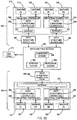
- FIGS. 3A and 3B illustrate a data analytics system environment 300 with alternative gateway configurations in exemplary implementations.
- a data analytics service 302 is configured to receive data gathered from machines and/or machine systems of plants (102, 106, 116, 124) and process, analyze, and present organized data to the machine stakeholders.
- data analytics service 302 is a cloud-based system accessible via the Internet or similar communication protocols; however, other types of systems are also contemplated herein.
- analytics data service 302 includes an analytics storage system 304 for data storage.
- Data analytics service 302 includes a processor system 306 configured to organize the data and perform various data analysis methods using the data to prepare the data for display to the machine stakeholders.
- the processor system 306 since it has access to the data from multiple machines (e.g., machines 104, 106, 110, 112, 118, 120, 126, 128), is able to integrate the data from the different locations where the machines are located and present the data to the machine stakeholders from a single source.
- the data processed by processor system 306 is accessible by a dashboard system 308 comprising one or more graphical dashboards configured to present the data to the machine stakeholders.
- the graphical dashboards are accessible by the machine stakeholders using OEM tools 310 such as FACTORYTALK Analytics for Machines software provided by Rockwell Automation, Inc.
- machines 104, 106 of plant 102 include an integrated controller 314, 316.
- Each controller 314, 316 is configured to generate a predefined data structure 318, 320 populated with specific data.
- the specific data include OEM identifying information, machine state information, actual part production or count information, ideal part production or count information, machine event information, and specific machine variable information.
- the OEM identifying information identifies the maker or builder of the machine and allows the analytics data service 302 to group or categorize the data for a single OEM together that is separated from the information of other OEMs.
- the machine OEM accesses the service 302 to view the stored data, only the data for the single OEM is delivered to the OEM dashboard, leaving machine data for other OEMs hidden or unaccessed by the dashboard tools.
- the OEM identifying information may also identify the particular machine make, model, or type together with other information machine specs. The location of the machine can also be included.
- the machine state information includes data identifying a history of the operating states of the machine and the times in which each of the operating states was encountered. This information includes pre-processed calculated information identifying the duration of each of the machine states as part of the data structure to reduce the need for the analytics data service 302 to calculate the information.
- the actual part count information includes data indicating how many parts has the particular machine has made over a period or periods of time.
- the part count information may include both the number of good parts produced as well as the number of bad parts produced.
- the ideal part count information includes the number of good parts that the machine should have produced during productive states such as, for example, when the machine was in one or more operational states and with adequate supplies to produce parts.
- the ideal part production or count information may be calculated based on a comparison of the duration of productive machine states with the ideal time it takes to produce a good part in a productive machine state.
- the machine event information includes information related to logged events in the machine. Events such as low or inadequate supplies, faults, operation starts and stops, and other flagged and stored events.
- the specific machine variable information may include the data values for specific variables that are important or of interest to the machine stakeholders and that should be included in at least one of the dahsboards.
- the format and configuration of data structures 318, 320 are the same, but the data contained therein is respective to each machine 104, 106.
- a respective gateway 322, 324 has access to the data structures 318, 320, and in one embodiment, to only the specific predefined data structures 318, 320. That is, access to other types of data structures or data information not organized according to the format of data structures 318, 320 by gateways 322, 324 is prohibited.
- Gateways 322, 324 communicate with controllers 314, 316 to obtain their respective data structures 318, 320 and upload the data structures 318, 320 to the data analytics service 302 for storage in the storage system 304.
- gateways 322, 324 (and all gateways described herein) simply facilitate the transfer of data structures 318, 320 from machines 104, 106 to the analytics data service 302.
- gateways 322, 324 include the protocols needed to communicate with machines 104, 106 and analytics data service 302 including security protocols, handshaking protocols, and the like.
- the gateway 322, 324 and controllers 314, 316 since the format and configuration of data structures 318, 320 are predefined and programmed into the gateway 322, 324 and controllers 314, 316, if a gateway 322, 324 fails to find a data structure 318, 320 in a controller 314, 316, the gateway 322, 324 does not have data to forward on to the analytics data service 302. That is, if the data structure 318, 320 is not populated or constructed by the controller 314, 316, the gateway 322, 324 does not acquire the relevant data parts through investigation of other parameters in the controller 314, 316.
- machines 110, 112 of plant 108 include an integrated controller 328, 330 configured to generate predefined data structures 332, 334 identical in format and configuration as those of data structures 318, 320.
- first gateway environment 312 includes a dedicated gateway 322, 324 for each machine 104, 106
- second gateway environment 326 includes a single gateway 336 for the plurality of machines 110, 112. Gateway 336 communicates with machines 110, 112 to obtain their respective data structures 318, 320 and upload the data structures 318, 320 to the data analytics service 302 for storage in the storage system 304.
- machines 118, 120 of plant 116 are controlled by a local industrial controller 340 while another plurality of machines 342, 344 is controlled by another local industrial controller 346.
- Machines 118, 120, 342, 344 are shown to include machines without an integrated controller; however, embodiments of the invention contemplate machines 118, 120, 342, 344 may have integrated controllers such as described above.
- industrial controllers 340, 342 are configured to generate predefined data structures 348, 350 including data acquired from respective machines 118, 120, 342, 344 and data generated during control thereof.
- Data structures 348, 350 are identical in format and configuration as those of data structures 318, 320, 332, 334 described above.
- a respective dedicated gateway 352, 354 has access to the data structures 348, 350 as described herein and uploads the unaltered data structures 318, 320 to the data analytics service 302 for storage in the storage system 304.
- a fourth gateway environment 356 another example of data transfer to analytics data service 302 is illustrated.
- machines 126, 128 of plant 124 are controlled by a local industrial controller 358 while another plurality of machines 360, 362 is controlled by another local industrial controller 364.
- Industrial controllers 358, 364 configured to generate predefined data structures 366, 368 identical in format and configuration as those of the other data structures described herein.
- third gateway environment 338 includes a dedicated gateway 352, 354 for each industrial controller 340, 346
- fourth gateway environment 356 includes a single gateway 370 for the plurality of industrial controllers 358, 364.
- Gateway 370 communicates with industrial controllers 358, 364 to obtain their respective data structures 366, 368 and upload them to the data analytics service 302 for storage in the storage system 304.
- FIG. 4 illustrates a data analytics operation 400 in an exemplary implementation.
- Operation 400 begins with outputting machine data to a gateway device at step 402.
- the gateway device e.g., gateway 322
- the gateway device receives the data from another point of data streaming in the industrial automation environment such as a database storage system, application integration platform, or the like.
- the industrial component e.g., controller, storage, etc.
- providing the machine data to the gateway device may, in one embodiment, provide the data according to a predefined data structure to facilitate downstream processing and analysis of the machine data.
- the gateway device itself may be configured to re-organize the machine data into the predefined data structure.
- the machine data output to the gateway device is provided, by the gateway device, to a data analysis/analytics service at step 404. While the gateway devices configured to send or output machine data to the data analytics service, the data analytics service and other external applications are prevented from reaching beyond the gateway device into the industrial automation environment in which the machines are located using the gateway device as a router or relay. In this manner, the gateway device provides a firewall to block external requests from accessing or probing the data and other aspects of the industrial automation environment.
- the data acquired from the machine system and populated in the known data structure in of the automation environment includes, for each machine: current machine state, current event, available time, running time, downtime, good parts produced, scrap parts produced, part count ratios, ideal cycle time, configurable process variables (e.g., temperature, voltage, energy use, etc.), and configurable counters (e.g., material consumed, machine cycles, etc.).
- properties of this machine information gathered by the gateway device and transmitted to the data analytics service include properties of the machines considered to be informational regarding operation of the machine without divulging information more sensitive to a company's interest who operates the machines.
- the data from a packing machine may include the number of successful operations for which the machine was designed (e.g., the number of successful packages created), the actual product within the successful packages may not be discernible therefrom. Accordingly, the machine builder or OEM who supplied the machine to the customer company may be able to analyze the operational data of a machine without knowing specific details regarding the customer company's product operated on or used in the machine's process.
- the machine data is stored in a memory system such as analytics storage system 304 and joined with other machine data such as customer, location, machine type and model number.
- the machine data is pre-processed at step 408 to make the raw machine data easier to query and easier to produce the calculations required to populate the dashboards.
- the processed data may be stored in analytics storage system 304 until a request is received at step 410 from a machine stakeholder's computing device to display on a display of the computing device one or more dashboards containing the machine's data and the calculated metrics.
- the machine stakeholder's computing device may include mobile computing devices, such as cell phones, tablet computers, laptop computers, and notebook computers, as well as any other type of mobile computing devices and any combination or variation thereof.
- the system queries the machine data for the requested machines and requested timeframe.
- Raw and summarized machine data are used at step 412 to calculate KPIs that appear on the dashboards such as Availability, Performance, Quality, overall equipment effectiveness (OEE), mean time in state (MTIS), mean time out of state (MTOS), actual cycle time, etc.
- One or more dashboards are populated at step 414 by the dashboard system or processor system with the machine and calculated data corresponding to the information designed to be visually displayed thereon. Following the dashboard population, the dashboard is delivered to the machine stakeholder's display device at step 416.
- FIG. 5 illustrates a dashboard 500 showing a plurality of machines machine 502-510 in a dashboard machine pane 512.
- Exemplary machine information illustrated for each machine 502-510 includes the machine's name 514, owner 516, address 518, and some of its metrics data 520 both graphical- and text-based.
- a legend 522 of machine states provides an explanation of the graphical depiction of metrics data 520.
- a geographical or political map 524 displayed in the dashboard 500 includes location markers 526 identifying the geographical location of the machines 502-510.
- the map 524 allows the machine stakeholder to view the machine locations in context with one another in an example. Differences, similarities, and other comparisons between the machines based on location may be discernible based on dashboard 500.
- a selection or other user input of one of the machines 502-510 causes a machinespecific dashboard 600 to be illustrated as shown in FIG. 6 .
- machinespecific data corresponding with "A Demo Machine 2" i.e., machine 504 is illustrated in dashboard 600.
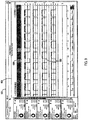
- Dashboard 600 may include, in one embodiment, a machine state timeline pane 602 in which the data corresponding with the machine's historical states are shown. In one example, as illustrated, a 24-hour period of machine states may be displayed. Additional machine state history may be illustrated by user-selection of a machine state history link 604, which, referring to FIG. 7 , illustrates a state history dashboard 700 for the selected machine (e.g., machine 504). In a state history pane 702, details regarding the operating states for the machine are displayed including the state type, start time, duration, category, and description in one embodiment. However, additional state history data may be displayed in addition to or in an alternative to that shown in state history dashboard 700.
- a machine state timeline pane 602 in which the data corresponding with the machine's historical states are shown. In one example, as illustrated, a 24-hour period of machine states may be displayed. Additional machine state history may be illustrated by user-selection of a machine state history link 604, which, referring to FIG. 7 , illustrates a state history dashboard
- dashboard 600 may also include a machine event pane 606 in which the data corresponding with machine events are shown.
- a listing of a top number of occurring events is displayed in graphical and tabular formats. The listing may display the top three events, the top five events, or some other number of top events as space and design allow.
- Additional machine event history may be illustrated by user-selection of a machine event history link 608, which, referring to FIG. 8 , illustrates an event history dashboard 800 for the selected machine.
- details regarding historical events for the machine are displayed including the event category, description, start time, and duration in one embodiment.
- additional state history data may be displayed in addition to or in an alternative to that shown in event history dashboard 800.
- dashboard 600 may also include a machine variables pane 610 in which one or more machine variables 612 together with their corresponding values are shown.
- a trend dashboard 900 as illustrated in FIG. 9 may be displayed in which the trends 902 for one or more process variables (e.g., TSV1, TSV2, TSV3, TSV4, TSV5) are shown in a trend pane 904.
- Trend pane 904 also includes a graphical representation 906 of the machine states of the selected machine corresponding with the process variable trend data.
- dashboard 600 may further include additional data panes illustrating machine system data acquired from the machines or calculated based on the acquired data.
- dashboard 600 includes a parts pane 908 that graphically illustrates the number of good parts and bad parts produced by the machine, a KPI pane 910 that displays KPI data, and a MTIS/MTOS pane 912 that displays MTIS and MTOS information calculated from the acquired machine data.
- Additional machine data acquired from the machines of the machine system 204 may be displayed according to the design of the various dashboards created to display machine information to the computing machines of the machine stakeholders.
- the dashboard designs are predefined and are not configurable by the machine stakeholders via their computing machines.
- feedback regarding dashboard data presentation may be accepted by the operator of the analytics data service 302 from the machine stakeholders to create dashboards helpful to their understanding and analysis of the operation of their machines in the field.
- FIG. 10 illustrates a computing system 1000, which is representative of any system or collection of systems in which the various applications, services, scenarios, and processes disclosed herein may be implemented.
- Examples of computing system 1000 include, but are not limited to, desktop computers, laptop computers, tablet computers, computers having hybrid form-factors, mobile phones, smart televisions, wearable devices, server computers, blade servers, rack servers, and any other type of computing system (or collection thereof) suitable for carrying out the application launching operations described herein.
- Such systems may employ one or more virtual machines, containers, or any other type of virtual computing resource in the context of supporting enhanced group collaboration.
- Computing system 1000 may be implemented as a single apparatus, system, or device or may be implemented in a distributed manner as multiple apparatuses, systems, or devices.
- Computing system 1000 includes, but is not limited to, processing system 1002, storage system 1004, software 1006, communication interface system 1008, and user interface system 1010.
- Processing system 1002 is operatively coupled with storage system 1004, communication interface system 1008, and user interface system 1010.
- Processing system 1002 loads and executes software 1006 from storage system 1004.
- Software 1006 includes application 1012, which is representative of a software application executed by a processor and programmed to execute the methods described herein.
- application 1012 When executed by processing system 1002 to facilitate and guide pre-booking requests, application 1012 directs processing system 1002 to operate as described herein for at least the various processes, operational scenarios, and sequences discussed in the foregoing implementations.
- Computing system 1000 may optionally include additional devices, features, or functionality not discussed for purposes of brevity.
- processing system 1002 may comprise a micro-processor and other circuitry that retrieves and executes software 1006 from storage system 1004.
- Processing system 1002 may be implemented within a single processing device, but may also be distributed across multiple processing devices or sub-systems that cooperate in executing program instructions. Examples of processing system 1002 include general purpose central processing units, application specific processors, and logic devices, as well as any other type of processing device, combinations, or variations thereof.
- Storage system 1004 may comprise any computer readable storage media readable by processing system 1002 and capable of storing software 1006.
- Storage system 1 004 may include volatile and nonvolatile, removable and non-removable media implemented in any method or technology for storage of information, such as computer readable instructions, data structures, program modules, or other data. Examples of storage media include random access memory, read only memory, magnetic disks, optical disks, flash memory, virtual memory and non-virtual memory, magnetic cassettes, magnetic tape, magnetic disk storage or other magnetic storage devices, or any other suitable storage media. In no case is the computer readable storage media a propagated signal.
- storage system 1004 may also include computer readable communication media over which at least some of software 1006 may be communicated internally or externally.
- Storage system 1004 may be implemented as a single storage device, but may also be implemented across multiple storage devices or sub-systems co-located or distributed relative to each other.
- Storage system 1004 may comprise additional elements, such as a controller, capable of communicating with processing system 1002 or possibly other systems.
- Software 1006 in general, and application 1012 in particular, may be implemented in program instructions and among other functions may, when executed by processing system 1002, direct processing system 1002 to operate as described with respect to the various operational scenarios, sequences, and processes illustrated herein.
- application 1012 may include program instructions for facilitating service provider booking procedures such at that described in method 400.
- program instructions may include various components or modules that cooperate or otherwise interact to carry out the various processes and operational scenarios described herein.
- the various components or modules may be embodied in compiled or interpreted instructions, or in some other variation or combination of instructions.
- Software 1006 may include additional processes, programs, or components, such as operating system software, virtual machine software, or other application software, in addition to or that include application 1012.
- Software 1006 may also comprise firmware or some other form of machine-readable processing instructions executable by processing system 1002.
- application 1012 may, when loaded into processing system 1002 and executed, transform a suitable apparatus, system, or device (of which computing system 1000 is representative) overall from a general-purpose computing system into a special-purpose computing system customized to enhance entity classification operations.
- encoding application 1012 on storage system 1004 may transform the physical structure of storage system 1004.
- the specific transformation of the physical structure may depend on various factors in different implementations of this description. Examples of such factors may include, but are not limited to, the technology used to implement the storage media of storage system 1004 and whether the computer-storage media are characterized as primary or secondary storage, as well as other factors.
- application 1012 may transform the physical state of the semiconductor memory when the program instructions are encoded therein, such as by transforming the state of transistors, capacitors, or other discrete circuit elements constituting the semiconductor memory.
- a similar transformation may occur with respect to magnetic or optical media.
- Other transformations of physical media are possible without departing from the scope of the present description, with the foregoing examples provided only to facilitate the present discussion.
- Communication interface system 1008 may include communication connections and devices that allow for communication with other computing systems (not shown) over communication networks (not shown). Examples of connections and devices that together allow for inter-system communication may include network interface cards, antennas, power amplifiers, RF circuitry, transceivers, and other communication circuitry. The connections and devices may communicate over communication media to exchange communications with other computing systems or networks of systems, such as metal, glass, air, or any other suitable communication media.
- the aforementioned media, connections, and devices are well known and need not be discussed at length here.
- User interface system 1010 may include a keyboard, a mouse, a voice input device, a touch input device for receiving a touch gesture from a user, a motion input device for detecting non-touch gestures and other motions by a user, and other comparable input devices and associated processing elements capable of receiving user input from a user.
- Output devices such as a display, speakers, haptic devices, and other types of output devices may also be included in user interface system 1010.
- the input and output devices may be combined in a single device, such as a display capable of displaying images and receiving touch gestures.
- the aforementioned user input and output devices are well known in the art and need not be discussed at length here.
- User interface system 1010 may also include associated user interface software executable by processing system 1002 in support of the various user input and output devices discussed above. Separately or in conjunction with each other and other hardware and software elements, the user interface software and user interface devices may support a graphical user interface, a natural user interface, or any other type of user interface, in which a user interface to an application may be presented.
- Communication between computing system 1000 and other computing systems may occur over a communication network or networks and in accordance with various communication protocols, combinations of protocols, or variations thereof. Examples include intranets, internets, the Internet, local area networks, wide area networks, wireless networks, wired networks, virtual networks, software defined networks, data center buses, computing backplanes, or any other type of network, combination of network, or variation thereof.
- the aforementioned communication networks and protocols are well-known and need not be discussed at length here. In any of the aforementioned examples in which data, content, or any other type of information is exchanged, the exchange of information may occur in accordance with any of a variety of well-known data transfer protocols.
Landscapes
- Engineering & Computer Science (AREA)
- Physics & Mathematics (AREA)
- General Physics & Mathematics (AREA)
- Business, Economics & Management (AREA)
- Human Resources & Organizations (AREA)
- General Engineering & Computer Science (AREA)
- Automation & Control Theory (AREA)
- Theoretical Computer Science (AREA)
- Quality & Reliability (AREA)
- Manufacturing & Machinery (AREA)
- Human Computer Interaction (AREA)
- Strategic Management (AREA)
- Economics (AREA)
- Entrepreneurship & Innovation (AREA)
- Educational Administration (AREA)
- Game Theory and Decision Science (AREA)
- Marketing (AREA)
- Operations Research (AREA)
- Tourism & Hospitality (AREA)
- General Business, Economics & Management (AREA)
- Development Economics (AREA)
- Databases & Information Systems (AREA)
- Data Mining & Analysis (AREA)
- Testing And Monitoring For Control Systems (AREA)
- General Factory Administration (AREA)
Claims (15)
- Un ou plusieurs support(s) de stockage lisible(s) par ordinateur sur lequel/lesquels sont stockées des instructions de programme, dans lequel/lesquels les instructions de programme, lorsqu'elles sont exécutées par un système informatique (302), ordonnent au système informatique de :recevoir (406) un ensemble de données de machine (318, 320, 332, 334) à partir d'un dispositif passerelle (322, 344, 336) dans un environnement d'automatisation industrielle (312, 326), l'ensemble de données de machine comprenant des données de fonctionnement d'une pluralité de machines d'automatisation industrielle (104, 106, 110, 112) contrôlées par au moins un contrôleur (314, 316, 328, 334) de l'environnement d'automatisation industrielle,où l'ensemble de données de machine est conforme à un format de données prédéfini et comprend :des informations d'identification de fabricant d'équipement d'origine, OEM, soit Original Equipment Manufacturer ;des informations d'état de machine identifiant :au moins un état de fonctionnement de la machine d'automatisation industrielle ; etune durée respective de l'au moins un état de fonctionnement ; etdes informations de production idéale identifiant un nombre de pièces que la machine d'automatisation industrielle aurait dû produire pendant un ou plusieurs état(s) de machine productif(s) de l'au moins un état de fonctionnement de la machine d'automatisation industrielle ;regrouper ou catégoriser ensemble les données de machine pour chaque OEM en utilisant les informations d'identification d'OEM ;recevoir (410) une demande d'un OEM pour afficher un tableau de bord ;générer (412) des données de métriques (520) sur la base de l'ensemble de données de machine associées à I'OEM ;stocker les données de métriques dans un support de stockage lisible par ordinateur ;générer (414) un tableau de bord de données (500 ; 600) sur la base des données de métriques stockées ; etdélivrer le tableau de bord de données à un dispositif d'affichage d'un dispositif configuré pour communiquer avec le système informatique, où le tableau de bord de données est accessible par I'OEM en utilisant des outils OEM (310).
- Un ou plusieurs support(s) de stockage lisible(s) par ordinateur de la revendication 1, dans lequel/lesquels les instructions de programme qui ordonnent au système informatique de recevoir l'ensemble de données de machine à partir du dispositif passerelle dans l'environnement d'automatisation industrielle, ordonnent au système informatique de recevoir un premier ensemble de données de machine (332) correspondant à une première machine (110) d'un premier environnement d'automatisation industrielle (326) à partir d'un premier dispositif passerelle (336) ; et
dans lequel/lesquels les instructions de programme ordonnent en outre au système informatique de recevoir un deuxième ensemble de données de machine (334) correspondant à une deuxième machine (112) du premier environnement d'automatisation industrielle à partir du premier dispositif passerelle. - Un ou plusieurs support(s) de stockage lisible(s) par ordinateur de la revendication 2, dans lequel/lesquels les instructions de programme ordonnent en outre au système informatique de recevoir un troisième ensemble de données de machine (318) correspondant à une première machine (104) d'un deuxième environnement d'automatisation industrielle (312) à partir d'un deuxième dispositif passerelle (318) ; et
dans lequel/lesquels le premier environnement d'automatisation industrielle est situé dans un emplacement géographique distinct d'un emplacement géographique du deuxième environnement d'automatisation industrielle. - Un ou plusieurs support(s) de stockage lisible(s) par ordinateur de la revendication 3, dans lequel/lesquels les instructions de programme ordonnent en outre au système informatique de générer un tableau de bord d'emplacement (500) configuré pour afficher les emplacements géographiques (526) des premier et deuxième environnements d'automatisation industrielle sur une carte (524).
- Un ou plusieurs support(s) de stockage lisible(s) par ordinateur de l'une des revendications 1 à 4, dans lequel/lesquels les instructions de programme qui ordonnent au système informatique de générer un tableau de bord de données sur la base des données de métriques stockées ordonnent au système informatique de générer le tableau de bord de données comprenant :un volet chronologique d'états de machine (602) comprenant un historique d'états de fonctionnement de machine ;un volet d'événements de machine (606) comprenant un historique d'événements de machine ; etun volet de variables de machine (610) comprenant une pluralité d'identifiants de variables de machine (612) avec des valeurs de variables correspondantes.
- Un ou plusieurs support(s) de stockage lisible(s) par ordinateur de l'une des revendications 1 à 5, dans lequel/lesquels l'ensemble de données de machine comprend des données de machine organisées selon une structure de données prédéfinie.
- Un ou plusieurs support(s) de stockage lisible(s) par ordinateur de l'une des revendications 1 à 6, dans lequel/lesquels les instructions de programme qui ordonnent au système informatique de générer des données de métriques ordonnent au système informatique de :déterminer une métrique de disponibilité de machine sur la base d'un temps d'exécution fonctionnel de la machine d'automatisation industrielle ;déterminer une métrique de performance de machine sur la base d'un temps de cycle de la machine d'automatisation industrielle ; etdéterminer une métrique de qualité de machine sur la base d'une comparaison du nombre de bonnes pièces produites par la machine d'automatisation industrielle avec le nombre de mauvaises pièces produites par la machine d'automatisation industrielle ; et/oudans lequel/lesquels les instructions de programme ordonnent en outre au système informatique de calculer une efficacité globale d'équipement de la machine d'automatisation industrielle sur la base de la métrique de disponibilité de machine, de la métrique de performance de machine et de la métrique de qualité de machine.
- Procédé de génération d'un tableau de bord (500 ; 600) comprenant des données de machine d'une machine d'automatisation industrielle (104, 106, 110, 112) dans un environnement d'automatisation industrielle (312, 326), le procédé comprenant :recevoir (406) un ensemble de données de machine (318, 320, 332, 334) à partir d'un dispositif passerelle (322, 324, 336) dans un environnement d'automatisation industrielle (312, 326), les données de machine comprenant des données de fonctionnement d'une machine d'automatisation industrielle (104, 106, 110, 112) contrôlée par au moins un contrôleur (314, 316, 328, 330) de l'environnement d'automatisation industrielle, où l'ensemble de données de machine est conforme à un format de données prédéfini et comprend :des informations d'identification de fabricant d'équipement d'origine, OEM, soit Original Equipment Manufacturer ;des informations d'état de machine identifiant :au moins un état de fonctionnement de la machine d'automatisation industrielle ; etune durée respective de l'au moins un état de fonctionnement ; etdes informations de production idéale identifiant un nombre de pièces que la machine d'automatisation industrielle aurait dû produire pendant un ou plusieurs état(s) de machine productif(s) de l'au moins un état de fonctionnement de la machine d'automatisation industrielle ;regrouper ou catégoriser ensemble les données de machine pour chaque OEM en utilisant les informations d'identification d'OEM ;recevoir (410) une demande d'un OEM pour afficher un tableau de bord ;générer (412) une pluralité de données de métriques sur la base des données de machine associées à I'OEM ;stocker la pluralité de données de métriques dans un support de stockage lisible par ordinateur ;générer (414) un tableau de bord de données (500 ; 600) sur la base de la pluralité de données de métriques stockée ; etdélivrer le tableau de bord de données à un dispositif d'affichage d'un dispositif, où le tableau de bord de données est accessible par I'OEM en utilisant des outils OEM (310).
- Procédé de la revendication 8, dans lequel la réception de l'ensemble de données de machine à partir du dispositif passerelle dans l'environnement d'automatisation industrielle comprend la réception d'un premier ensemble (332) de données de machine correspondant à une première machine (110) d'un premier environnement d'automatisation industrielle (326) à partir d'un premier dispositif passerelle (336) ; et
comprenant en outre la réception d'un deuxième ensemble de données de machine (334) correspondant à une deuxième machine (112) du premier environnement d'automatisation industrielle à partir du premier dispositif passerelle. - Procédé de la revendication 9, comprenant en outre la réception d'un troisième ensemble de données de machine (318) correspondant à une première machine (104) d'un deuxième environnement d'automatisation industrielle (312) à partir d'un deuxième dispositif passerelle (322) ; etdans lequel le premier environnement d'automatisation industrielle est situé dans un emplacement géographique distinct d'un emplacement géographique du deuxième environnement d'automatisation industrielle ; et/oucomprenant en outre la génération d'un tableau de bord d'emplacement (500) configuré pour afficher les emplacements géographiques (526) des premier et second environnements d'automatisation industrielle sur une carte (524).
- Procédé de l'une des revendications 8 à 10, dans lequel la génération du tableau de bord de données sur la base de la pluralité de données de métriques stockée comprend la génération du tableau de bord de données comprenant :un volet chronologique d'états de machine (604) comprenant un historique d'états de fonctionnement de machine ;un volet d'événements de machine (606) comprenant un historique d'événements de machine ; etun volet de variables de machine (610) comprenant une pluralité d'identifiants de variables de machine (612) avec des valeurs de variables correspondantes.
- Procédé de la revendication 8 à 11, dans lequel l'ensemble de données de machine comprend des données de machine organisées selon une structure de données prédéfinie.
- Système pour générer un tableau de bord comprenant des données de machine d'un système de machine d'automatisation industrielle dans un environnement d'automatisation industrielle, le système comprenant :un système informatique (302) d'un service de données analytiques ;un dispositif passerelle (322, 324, 336) configuré pour :acquérir (402) des données de machine générées par le système de machine d'automatisation industrielle (104, 106, 110, 112), où les données de machine sont conformes à un format de données prédéfini et comprennent :des informations d'identification de fabricant d'équipement d'origine, OEM, soit Original Equipment Manufacturer ;des informations d'état de machine identifiant :au moins un état de fonctionnement du système de machine d'automatisation industrielle ; etune durée respective de l'au moins un état de fonctionnement ; etdes informations de production idéale identifiant un nombre de pièces que le système de machine d'automatisation industrielle aurait dû produire pendant un ou plusieurs état(s) de machine productif(s) de l'au moins un état de fonctionnement du système de machine d'automatisation industrielle ;transmettre (404) les données de machine au système informatique ; etdans lequel le système informatique comprend :un support de stockage lisible par ordinateur (304) configuré pour stocker les données de machine ;un système de processeur (306) configuré pour :regrouper ou catégoriser ensemble les données de machine pour chaque OEM en utilisant les informations d'identification d'OEM ;recevoir (410) une demande d'un OEM pour afficher un tableau de bord ;générer (412) une pluralité de données de métriques sur la base des données de machine associées à I'OEM ; etstocker les données de métriques dans le support de stockage lisible par ordinateur ; etun système de tableau de bord (308) configuré pour :générer (414) un tableau de bord de données (500 ; 600) sur la base des données de métriques stockées ; etdélivrer (416) le tableau de bord de données à un dispositif d'affichage d'un dispositif demandant le tableau de bord de données au système informatique, où le tableau de bord de données est accessible par I'OEM en utilisant des outils OEM (310).
- Système de la revendication 13, dans lequel le dispositif passerelle est en outre configuré pour organiser les données de machine acquises sur la base d'une structure de données prédéfinie avant de transmettre les données de machine au système informatique ; oudans lequel le dispositif passerelle est en outre configuré pour acquérir les données de machine à partir d'un contrôleur industriel (314, 316, 328, 330) de l'environnement d'automatisation industrielle configuré pour contrôler le système de machine d'automatisation industrielle ; oudans lequel le dispositif passerelle est en outre configuré pour fournir des services de pare-feu pour bloquer l'accès externe à l'environnement d'automatisation industrielle.
- Système de la revendication 13 ou 14, dans lequel, pour une machine au sein du système de machine d'automatisation industrielle, le tableau de bord de données comprend :un volet chronologique d'états de machine (604) comprenant un historique d'états de fonctionnement de la machine ;un volet d'événements de machine (606) comprenant un historique d'événements de la machine ; etun volet de variables de machine (610) comprenant une pluralité d'identifiants de variables (612) avec des valeurs de variables correspondantes de la machine ; et/oudans lequel le système de processeur est en outre configuré pour calculer une efficacité globale d'équipement de la machine sur la base de :un temps d'exécution fonctionnel de la machine ;un temps de cycle de la machine ; etune comparaison du nombre de bonnes pièces produites par la machine avec le nombre de mauvaises pièces produites par la machine.
Applications Claiming Priority (2)
| Application Number | Priority Date | Filing Date | Title |
|---|---|---|---|
| US201662417713P | 2016-11-04 | 2016-11-04 | |
| US15/720,232 US20180129191A1 (en) | 2016-11-04 | 2017-09-29 | Industrial automation system machine analytics for a connected enterprise |
Publications (3)
| Publication Number | Publication Date |
|---|---|
| EP3318941A2 EP3318941A2 (fr) | 2018-05-09 |
| EP3318941A3 EP3318941A3 (fr) | 2018-05-30 |
| EP3318941B1 true EP3318941B1 (fr) | 2021-12-29 |
Family
ID=60268261
Family Applications (1)
| Application Number | Title | Priority Date | Filing Date |
|---|---|---|---|
| EP17200073.9A Active EP3318941B1 (fr) | 2016-11-04 | 2017-11-06 | Analyse de machine de système d'automatisation industrielle pour une entreprise connectée |
Country Status (3)
| Country | Link |
|---|---|
| US (1) | US20180129191A1 (fr) |
| EP (1) | EP3318941B1 (fr) |
| CN (1) | CN108021108B (fr) |
Families Citing this family (21)
| Publication number | Priority date | Publication date | Assignee | Title |
|---|---|---|---|---|
| WO2020018544A1 (fr) * | 2018-07-17 | 2020-01-23 | iT SpeeX LLC | Procédé, système et produit-programme informatique pour harmoniser des machines industrielles à l'aide d'un assistant industriel intelligent ayant un ensemble de commandes prédéfinies |
| US10715394B2 (en) * | 2018-10-29 | 2020-07-14 | Sap Portals Israel Ltd. | Data aggregation based on a heirarchical tree |
| CN113196189B (zh) * | 2018-11-01 | 2025-03-11 | 捷普有限公司 | 利用物联网工厂网关收集实时制造数据的系统和方法 |
| EP3977374A1 (fr) * | 2019-05-31 | 2022-04-06 | Abb Schweiz Ag | Procédé de configuration d'un système de surveillance utilisé pour surveiller des procédés industriels et des actifs industriels |
| CN113950696B (zh) * | 2019-06-14 | 2025-01-10 | 利乐拉瓦尔集团及财务有限公司 | 用于处理从放置在生产线中的传感器捕获的传感器输入数据的方法及其系统 |
| US11574219B2 (en) * | 2019-09-27 | 2023-02-07 | Rockwell Automation Technologies, Inc. | System and method for industrial automation rules engine |
| US11953887B2 (en) * | 2019-09-27 | 2024-04-09 | Rockwell Automation Technologies, Inc. | System and method for customer-specific naming conventions for industrial automation devices |
| EP3805882B1 (fr) * | 2019-10-10 | 2022-06-08 | Siemens Aktiengesellschaft | Système de guidage pour une installation technique pourvu de diagramme de courbe de tendance |
| JP7167072B2 (ja) * | 2020-02-19 | 2022-11-08 | 株式会社安川電機 | 生産システム、通信方法、及びプログラム |
| EP3920545B1 (fr) * | 2020-06-02 | 2024-02-14 | ABB Schweiz AG | Communication sans fil pour l'automatisation industrielle |
| CN112118299B (zh) * | 2020-09-04 | 2023-01-13 | 四川蜂巢智造云科技有限公司 | 一种用于设备管理数据与生产业务数据分离的系统 |
| US11835568B2 (en) | 2020-11-18 | 2023-12-05 | General Electric Company | Systems and methods for monitoring and diagnosing power system assets |
| US12346087B2 (en) * | 2020-12-04 | 2025-07-01 | Machinemetrics, Inc. | System and method for continuous machine monitoring at a KHz-scale |
| US12510876B2 (en) * | 2021-04-22 | 2025-12-30 | Baker Hughes Holdings Llc | Machine state visualization |
| CN113805531B (zh) * | 2021-09-22 | 2023-03-21 | 格致汽车科技股份有限公司 | 一种用于数控机床的全自动无人值守预警方法 |
| US20230205189A1 (en) * | 2021-12-23 | 2023-06-29 | Johnson Controls Tyco IP Holdings LLP | Connected equipment system |
| CN114545883A (zh) * | 2022-03-14 | 2022-05-27 | 湖南思特异科技有限公司 | 一种综合化工业设备运行状态监控系统 |
| EP4666142A1 (fr) * | 2023-03-31 | 2025-12-24 | Siemens Aktiengesellschaft | Procédé de configuration de modèle informatique d'indice de performance, procédé informatique, appareil, et dispositif informatique |
| US20240420391A1 (en) * | 2023-06-16 | 2024-12-19 | The Toronto-Dominion Bank | Intelligent dashboard search engine |
| TWI854947B (zh) * | 2023-08-09 | 2024-09-01 | 陽明海運股份有限公司 | 稽核運具運行和稽核改善運具運行的方法和伺服方法、客戶計算機、伺服器、電腦可讀取紀錄媒體 |
| CN119341956B (zh) * | 2024-12-20 | 2025-04-29 | 天信仪表集团有限公司 | 主从机轮询方法、设备、装置、存储介质及程序产品 |
Family Cites Families (27)
| Publication number | Priority date | Publication date | Assignee | Title |
|---|---|---|---|---|
| DE10152765B4 (de) * | 2001-07-13 | 2015-11-12 | Siemens Aktiengesellschaft | Verfahren zur elektronischen Bereitstellung von Diensten für Maschinen über eine Datenkommunikationsverbindung |
| US6975913B2 (en) * | 2001-07-13 | 2005-12-13 | Siemens Aktiengesellschaft | Database system and method for industrial automation services |
| US20040225955A1 (en) * | 2003-05-08 | 2004-11-11 | The Boeing Company | Intelligent information dashboard system and method |
| US8612864B2 (en) * | 2008-02-22 | 2013-12-17 | Applied Materials, Inc. | User interface with visualization of real and virtual data |
| KR20220155401A (ko) * | 2011-10-10 | 2022-11-22 | 프로그래시브 컴포넌츠 인터내셔널 코포레이션 | 툴링 활동들을 모니터링하기 위한 시스템 및 방법 |
| CN104025070A (zh) * | 2011-10-24 | 2014-09-03 | 施耐德电器工业公司 | 用于管理工业过程的系统和方法 |
| US9477936B2 (en) * | 2012-02-09 | 2016-10-25 | Rockwell Automation Technologies, Inc. | Cloud-based operator interface for industrial automation |
| US9405526B2 (en) * | 2012-08-07 | 2016-08-02 | Microsoft Technology Licensing, Llc | Initiating update operations |
| SG2012070017A (en) * | 2012-09-20 | 2014-04-28 | Rockwell Automation Asia Pacific Business Ctr Pte Ltd | Systems, methods, and software for presenting parameter set(s) for industrial automation devices |
| JP6423348B2 (ja) * | 2012-10-08 | 2018-11-14 | フィッシャー−ローズマウント システムズ,インコーポレイテッド | 動的に再使用可能なクラス |
| US10386827B2 (en) * | 2013-03-04 | 2019-08-20 | Fisher-Rosemount Systems, Inc. | Distributed industrial performance monitoring and analytics platform |
| US9665088B2 (en) * | 2014-01-31 | 2017-05-30 | Fisher-Rosemount Systems, Inc. | Managing big data in process control systems |
| US10026049B2 (en) * | 2013-05-09 | 2018-07-17 | Rockwell Automation Technologies, Inc. | Risk assessment for industrial systems using big data |
| US20140337277A1 (en) * | 2013-05-09 | 2014-11-13 | Rockwell Automation Technologies, Inc. | Industrial device and system attestation in a cloud platform |
| US9989958B2 (en) * | 2013-05-09 | 2018-06-05 | Rockwell Automation Technologies, Inc. | Using cloud-based data for virtualization of an industrial automation environment |
| US20140358256A1 (en) * | 2013-05-31 | 2014-12-04 | Rockwell Automation Technologies, Inc. | Systems, methods, and software to present human machine interfaces on a mobile device |
| US20150074749A1 (en) * | 2013-09-10 | 2015-03-12 | Rockwell Automation Technologies, Inc. | Remote asset management services for industrial assets |
| US9390246B2 (en) * | 2013-09-25 | 2016-07-12 | Intel Corporation | Creating secure original equipment manufacturer (OEM) identification |
| US20150106912A1 (en) * | 2013-10-16 | 2015-04-16 | Milacron Llc | Remote machine monitoring systems and services |
| EP3095013B1 (fr) * | 2014-01-16 | 2020-08-12 | ABB Schweiz AG | Procédé et système destinés à être utilisés en connexion avec un système de commande industriel |
| US9720404B2 (en) * | 2014-05-05 | 2017-08-01 | Honeywell International Inc. | Gateway offering logical model mapped to independent underlying networks |
| US11120371B2 (en) * | 2014-06-23 | 2021-09-14 | Sensia Netherlands B.V. | Systems and methods for cloud-based asset management and analysis regarding well devices |
| JP2016019281A (ja) * | 2014-07-07 | 2016-02-01 | ベドロック・オートメーション・プラットフォームズ・インコーポレーテッド | 産業用制御システムのオペレータ・アクション認証 |
| US9396015B2 (en) * | 2014-10-27 | 2016-07-19 | Ayla Networks, Inc. | Flexible device templates for connected consumer devices |
| US11243505B2 (en) * | 2015-03-16 | 2022-02-08 | Rockwell Automation Technologies, Inc. | Cloud-based analytics for industrial automation |
| US11513477B2 (en) * | 2015-03-16 | 2022-11-29 | Rockwell Automation Technologies, Inc. | Cloud-based industrial controller |
| US20160328808A1 (en) * | 2015-05-06 | 2016-11-10 | Kemeera Inc. Dba Fathom | Data aggregation and analytics for digital manufacturing |
-
2017
- 2017-09-29 US US15/720,232 patent/US20180129191A1/en not_active Abandoned
- 2017-11-02 CN CN201711064148.1A patent/CN108021108B/zh active Active
- 2017-11-06 EP EP17200073.9A patent/EP3318941B1/fr active Active
Non-Patent Citations (1)
| Title |
|---|
| None * |
Also Published As
| Publication number | Publication date |
|---|---|
| US20180129191A1 (en) | 2018-05-10 |
| EP3318941A3 (fr) | 2018-05-30 |
| CN108021108B (zh) | 2021-06-15 |
| CN108021108A (zh) | 2018-05-11 |
| EP3318941A2 (fr) | 2018-05-09 |
Similar Documents
| Publication | Publication Date | Title |
|---|---|---|
| EP3318941A2 (fr) | Analyse de machine de système d'automatisation industrielle pour une entreprise connectée | |
| US11227080B2 (en) | Industrial automation information contextualization method and system | |
| CN104142660B (zh) | 用于工业自动化的经由云平台的远程协助 | |
| US9929905B2 (en) | Cloud based drive monitoring solution | |
| CN107026894B (zh) | 用于通过工业资产递送自动通知的装置和方法 | |
| EP3822726A1 (fr) | Surveillance de composants de fabrication de systèmes d'application par rapport à des mesures spécifiques à l'application | |
| US20140337277A1 (en) | Industrial device and system attestation in a cloud platform | |
| US20160112283A1 (en) | Remote industrial monitoring and analytics using a cloud infrastructure | |
| US20160179359A1 (en) | Industrial automation visualization dashboard creation paradigm | |
| EP2704401A1 (fr) | Surveillance industrielle à distance utilisant une infrastructure en nuage | |
| US20130211870A1 (en) | Real-time tracking of product using a cloud platform | |
| US20160349967A1 (en) | Offline investigation in an industrial automation environment | |
| US20160349966A1 (en) | Device-to-device communication in an industrial automation environment | |
| US11822981B2 (en) | Common gateway platform | |
| US10847012B2 (en) | System and method for personalized alarm notifications in an industrial automation environment | |
| US11443467B2 (en) | Server systems and methods for utilizing a namespace property to correlate process tag values to corresponding events | |
| US20170108851A1 (en) | Industrial automation electronic pinboard | |
| US11449025B2 (en) | Unique UDTs to exploit the power of the connected enterprise |
Legal Events
| Date | Code | Title | Description |
|---|---|---|---|
| PUAI | Public reference made under article 153(3) epc to a published international application that has entered the european phase |
Free format text: ORIGINAL CODE: 0009012 |
|
| STAA | Information on the status of an ep patent application or granted ep patent |
Free format text: STATUS: THE APPLICATION HAS BEEN PUBLISHED |
|
| PUAL | Search report despatched |
Free format text: ORIGINAL CODE: 0009013 |
|
| AK | Designated contracting states |
Kind code of ref document: A2 Designated state(s): AL AT BE BG CH CY CZ DE DK EE ES FI FR GB GR HR HU IE IS IT LI LT LU LV MC MK MT NL NO PL PT RO RS SE SI SK SM TR |
|
| AX | Request for extension of the european patent |
Extension state: BA ME |
|
| AK | Designated contracting states |
Kind code of ref document: A3 Designated state(s): AL AT BE BG CH CY CZ DE DK EE ES FI FR GB GR HR HU IE IS IT LI LT LU LV MC MK MT NL NO PL PT RO RS SE SI SK SM TR |
|
| AX | Request for extension of the european patent |
Extension state: BA ME |
|
| RIC1 | Information provided on ipc code assigned before grant |
Ipc: H04L 29/06 20060101ALI20180423BHEP Ipc: G05B 19/418 20060101AFI20180423BHEP |
|
| STAA | Information on the status of an ep patent application or granted ep patent |
Free format text: STATUS: REQUEST FOR EXAMINATION WAS MADE |
|
| 17P | Request for examination filed |
Effective date: 20181130 |
|
| RBV | Designated contracting states (corrected) |
Designated state(s): AL AT BE BG CH CY CZ DE DK EE ES FI FR GB GR HR HU IE IS IT LI LT LU LV MC MK MT NL NO PL PT RO RS SE SI SK SM TR |
|
| STAA | Information on the status of an ep patent application or granted ep patent |
Free format text: STATUS: EXAMINATION IS IN PROGRESS |
|
| 17Q | First examination report despatched |
Effective date: 20190806 |
|
| REG | Reference to a national code |
Ref country code: DE Ref legal event code: R079 Ref document number: 602017051488 Country of ref document: DE Free format text: PREVIOUS MAIN CLASS: G05B0019418000 Ipc: G05B0019406300 |
|
| GRAP | Despatch of communication of intention to grant a patent |
Free format text: ORIGINAL CODE: EPIDOSNIGR1 |
|
| STAA | Information on the status of an ep patent application or granted ep patent |
Free format text: STATUS: GRANT OF PATENT IS INTENDED |
|
| RIC1 | Information provided on ipc code assigned before grant |
Ipc: G05B 19/4063 20060101AFI20210531BHEP Ipc: G06Q 10/06 20120101ALI20210531BHEP |
|
| INTG | Intention to grant announced |
Effective date: 20210621 |
|
| GRAS | Grant fee paid |
Free format text: ORIGINAL CODE: EPIDOSNIGR3 |
|
| GRAA | (expected) grant |
Free format text: ORIGINAL CODE: 0009210 |
|
| STAA | Information on the status of an ep patent application or granted ep patent |
Free format text: STATUS: THE PATENT HAS BEEN GRANTED |
|
| AK | Designated contracting states |
Kind code of ref document: B1 Designated state(s): AL AT BE BG CH CY CZ DE DK EE ES FI FR GB GR HR HU IE IS IT LI LT LU LV MC MK MT NL NO PL PT RO RS SE SI SK SM TR |
|
| REG | Reference to a national code |
Ref country code: GB Ref legal event code: FG4D |
|
| REG | Reference to a national code |
Ref country code: CH Ref legal event code: EP |
|
| REG | Reference to a national code |
Ref country code: AT Ref legal event code: REF Ref document number: 1459154 Country of ref document: AT Kind code of ref document: T Effective date: 20220115 |
|
| REG | Reference to a national code |
Ref country code: IE Ref legal event code: FG4D |
|
| REG | Reference to a national code |
Ref country code: DE Ref legal event code: R096 Ref document number: 602017051488 Country of ref document: DE |
|
| REG | Reference to a national code |
Ref country code: LT Ref legal event code: MG9D |
|
| PG25 | Lapsed in a contracting state [announced via postgrant information from national office to epo] |
Ref country code: RS Free format text: LAPSE BECAUSE OF FAILURE TO SUBMIT A TRANSLATION OF THE DESCRIPTION OR TO PAY THE FEE WITHIN THE PRESCRIBED TIME-LIMIT Effective date: 20211229 Ref country code: LT Free format text: LAPSE BECAUSE OF FAILURE TO SUBMIT A TRANSLATION OF THE DESCRIPTION OR TO PAY THE FEE WITHIN THE PRESCRIBED TIME-LIMIT Effective date: 20211229 Ref country code: FI Free format text: LAPSE BECAUSE OF FAILURE TO SUBMIT A TRANSLATION OF THE DESCRIPTION OR TO PAY THE FEE WITHIN THE PRESCRIBED TIME-LIMIT Effective date: 20211229 Ref country code: BG Free format text: LAPSE BECAUSE OF FAILURE TO SUBMIT A TRANSLATION OF THE DESCRIPTION OR TO PAY THE FEE WITHIN THE PRESCRIBED TIME-LIMIT Effective date: 20220329 |
|
| REG | Reference to a national code |
Ref country code: NL Ref legal event code: MP Effective date: 20211229 |
|
| REG | Reference to a national code |
Ref country code: AT Ref legal event code: MK05 Ref document number: 1459154 Country of ref document: AT Kind code of ref document: T Effective date: 20211229 |
|
| PG25 | Lapsed in a contracting state [announced via postgrant information from national office to epo] |
Ref country code: SE Free format text: LAPSE BECAUSE OF FAILURE TO SUBMIT A TRANSLATION OF THE DESCRIPTION OR TO PAY THE FEE WITHIN THE PRESCRIBED TIME-LIMIT Effective date: 20211229 Ref country code: NO Free format text: LAPSE BECAUSE OF FAILURE TO SUBMIT A TRANSLATION OF THE DESCRIPTION OR TO PAY THE FEE WITHIN THE PRESCRIBED TIME-LIMIT Effective date: 20220329 Ref country code: LV Free format text: LAPSE BECAUSE OF FAILURE TO SUBMIT A TRANSLATION OF THE DESCRIPTION OR TO PAY THE FEE WITHIN THE PRESCRIBED TIME-LIMIT Effective date: 20211229 Ref country code: HR Free format text: LAPSE BECAUSE OF FAILURE TO SUBMIT A TRANSLATION OF THE DESCRIPTION OR TO PAY THE FEE WITHIN THE PRESCRIBED TIME-LIMIT Effective date: 20211229 Ref country code: GR Free format text: LAPSE BECAUSE OF FAILURE TO SUBMIT A TRANSLATION OF THE DESCRIPTION OR TO PAY THE FEE WITHIN THE PRESCRIBED TIME-LIMIT Effective date: 20220330 |
|
| PG25 | Lapsed in a contracting state [announced via postgrant information from national office to epo] |
Ref country code: NL Free format text: LAPSE BECAUSE OF FAILURE TO SUBMIT A TRANSLATION OF THE DESCRIPTION OR TO PAY THE FEE WITHIN THE PRESCRIBED TIME-LIMIT Effective date: 20211229 |
|
| PG25 | Lapsed in a contracting state [announced via postgrant information from national office to epo] |
Ref country code: SM Free format text: LAPSE BECAUSE OF FAILURE TO SUBMIT A TRANSLATION OF THE DESCRIPTION OR TO PAY THE FEE WITHIN THE PRESCRIBED TIME-LIMIT Effective date: 20211229 Ref country code: SK Free format text: LAPSE BECAUSE OF FAILURE TO SUBMIT A TRANSLATION OF THE DESCRIPTION OR TO PAY THE FEE WITHIN THE PRESCRIBED TIME-LIMIT Effective date: 20211229 Ref country code: RO Free format text: LAPSE BECAUSE OF FAILURE TO SUBMIT A TRANSLATION OF THE DESCRIPTION OR TO PAY THE FEE WITHIN THE PRESCRIBED TIME-LIMIT Effective date: 20211229 Ref country code: PT Free format text: LAPSE BECAUSE OF FAILURE TO SUBMIT A TRANSLATION OF THE DESCRIPTION OR TO PAY THE FEE WITHIN THE PRESCRIBED TIME-LIMIT Effective date: 20220429 Ref country code: ES Free format text: LAPSE BECAUSE OF FAILURE TO SUBMIT A TRANSLATION OF THE DESCRIPTION OR TO PAY THE FEE WITHIN THE PRESCRIBED TIME-LIMIT Effective date: 20211229 Ref country code: EE Free format text: LAPSE BECAUSE OF FAILURE TO SUBMIT A TRANSLATION OF THE DESCRIPTION OR TO PAY THE FEE WITHIN THE PRESCRIBED TIME-LIMIT Effective date: 20211229 Ref country code: CZ Free format text: LAPSE BECAUSE OF FAILURE TO SUBMIT A TRANSLATION OF THE DESCRIPTION OR TO PAY THE FEE WITHIN THE PRESCRIBED TIME-LIMIT Effective date: 20211229 |
|
| PG25 | Lapsed in a contracting state [announced via postgrant information from national office to epo] |
Ref country code: PL Free format text: LAPSE BECAUSE OF FAILURE TO SUBMIT A TRANSLATION OF THE DESCRIPTION OR TO PAY THE FEE WITHIN THE PRESCRIBED TIME-LIMIT Effective date: 20211229 Ref country code: AT Free format text: LAPSE BECAUSE OF FAILURE TO SUBMIT A TRANSLATION OF THE DESCRIPTION OR TO PAY THE FEE WITHIN THE PRESCRIBED TIME-LIMIT Effective date: 20211229 |
|
| PG25 | Lapsed in a contracting state [announced via postgrant information from national office to epo] |
Ref country code: IS Free format text: LAPSE BECAUSE OF FAILURE TO SUBMIT A TRANSLATION OF THE DESCRIPTION OR TO PAY THE FEE WITHIN THE PRESCRIBED TIME-LIMIT Effective date: 20220429 |
|
| REG | Reference to a national code |
Ref country code: DE Ref legal event code: R097 Ref document number: 602017051488 Country of ref document: DE |
|
| PG25 | Lapsed in a contracting state [announced via postgrant information from national office to epo] |
Ref country code: DK Free format text: LAPSE BECAUSE OF FAILURE TO SUBMIT A TRANSLATION OF THE DESCRIPTION OR TO PAY THE FEE WITHIN THE PRESCRIBED TIME-LIMIT Effective date: 20211229 Ref country code: AL Free format text: LAPSE BECAUSE OF FAILURE TO SUBMIT A TRANSLATION OF THE DESCRIPTION OR TO PAY THE FEE WITHIN THE PRESCRIBED TIME-LIMIT Effective date: 20211229 |
|
| PLBE | No opposition filed within time limit |
Free format text: ORIGINAL CODE: 0009261 |
|
| STAA | Information on the status of an ep patent application or granted ep patent |
Free format text: STATUS: NO OPPOSITION FILED WITHIN TIME LIMIT |
|
| 26N | No opposition filed |
Effective date: 20220930 |
|
| PG25 | Lapsed in a contracting state [announced via postgrant information from national office to epo] |
Ref country code: SI Free format text: LAPSE BECAUSE OF FAILURE TO SUBMIT A TRANSLATION OF THE DESCRIPTION OR TO PAY THE FEE WITHIN THE PRESCRIBED TIME-LIMIT Effective date: 20211229 |
|
| PG25 | Lapsed in a contracting state [announced via postgrant information from national office to epo] |
Ref country code: IT Free format text: LAPSE BECAUSE OF FAILURE TO SUBMIT A TRANSLATION OF THE DESCRIPTION OR TO PAY THE FEE WITHIN THE PRESCRIBED TIME-LIMIT Effective date: 20211229 |
|
| P01 | Opt-out of the competence of the unified patent court (upc) registered |
Effective date: 20230404 |
|
| PG25 | Lapsed in a contracting state [announced via postgrant information from national office to epo] |
Ref country code: MC Free format text: LAPSE BECAUSE OF FAILURE TO SUBMIT A TRANSLATION OF THE DESCRIPTION OR TO PAY THE FEE WITHIN THE PRESCRIBED TIME-LIMIT Effective date: 20211229 |
|
| REG | Reference to a national code |
Ref country code: CH Ref legal event code: PL |
|
| REG | Reference to a national code |
Ref country code: BE Ref legal event code: MM Effective date: 20221130 |
|
| PG25 | Lapsed in a contracting state [announced via postgrant information from national office to epo] |
Ref country code: LI Free format text: LAPSE BECAUSE OF NON-PAYMENT OF DUE FEES Effective date: 20221130 Ref country code: CH Free format text: LAPSE BECAUSE OF NON-PAYMENT OF DUE FEES Effective date: 20221130 |
|
| PG25 | Lapsed in a contracting state [announced via postgrant information from national office to epo] |
Ref country code: LU Free format text: LAPSE BECAUSE OF NON-PAYMENT OF DUE FEES Effective date: 20221106 |
|
| PG25 | Lapsed in a contracting state [announced via postgrant information from national office to epo] |
Ref country code: IE Free format text: LAPSE BECAUSE OF NON-PAYMENT OF DUE FEES Effective date: 20221106 |
|
| PG25 | Lapsed in a contracting state [announced via postgrant information from national office to epo] |
Ref country code: BE Free format text: LAPSE BECAUSE OF NON-PAYMENT OF DUE FEES Effective date: 20221130 |
|
| PG25 | Lapsed in a contracting state [announced via postgrant information from national office to epo] |
Ref country code: HU Free format text: LAPSE BECAUSE OF FAILURE TO SUBMIT A TRANSLATION OF THE DESCRIPTION OR TO PAY THE FEE WITHIN THE PRESCRIBED TIME-LIMIT; INVALID AB INITIO Effective date: 20171106 |
|
| PG25 | Lapsed in a contracting state [announced via postgrant information from national office to epo] |
Ref country code: CY Free format text: LAPSE BECAUSE OF FAILURE TO SUBMIT A TRANSLATION OF THE DESCRIPTION OR TO PAY THE FEE WITHIN THE PRESCRIBED TIME-LIMIT Effective date: 20211229 |
|
| PG25 | Lapsed in a contracting state [announced via postgrant information from national office to epo] |
Ref country code: MK Free format text: LAPSE BECAUSE OF FAILURE TO SUBMIT A TRANSLATION OF THE DESCRIPTION OR TO PAY THE FEE WITHIN THE PRESCRIBED TIME-LIMIT Effective date: 20211229 |
|
| PG25 | Lapsed in a contracting state [announced via postgrant information from national office to epo] |
Ref country code: TR Free format text: LAPSE BECAUSE OF FAILURE TO SUBMIT A TRANSLATION OF THE DESCRIPTION OR TO PAY THE FEE WITHIN THE PRESCRIBED TIME-LIMIT Effective date: 20211229 |
|
| PG25 | Lapsed in a contracting state [announced via postgrant information from national office to epo] |
Ref country code: MT Free format text: LAPSE BECAUSE OF FAILURE TO SUBMIT A TRANSLATION OF THE DESCRIPTION OR TO PAY THE FEE WITHIN THE PRESCRIBED TIME-LIMIT Effective date: 20211229 |
|
| PGFP | Annual fee paid to national office [announced via postgrant information from national office to epo] |
Ref country code: DE Payment date: 20251022 Year of fee payment: 9 |
|
| PGFP | Annual fee paid to national office [announced via postgrant information from national office to epo] |
Ref country code: GB Payment date: 20251023 Year of fee payment: 9 |
|
| PGFP | Annual fee paid to national office [announced via postgrant information from national office to epo] |
Ref country code: FR Payment date: 20251023 Year of fee payment: 9 |