EP3319734B1 - System de distribution dosée d'un liquide et methode de fabrication - Google Patents
System de distribution dosée d'un liquide et methode de fabrication Download PDFInfo
- Publication number
- EP3319734B1 EP3319734B1 EP16738409.8A EP16738409A EP3319734B1 EP 3319734 B1 EP3319734 B1 EP 3319734B1 EP 16738409 A EP16738409 A EP 16738409A EP 3319734 B1 EP3319734 B1 EP 3319734B1
- Authority
- EP
- European Patent Office
- Prior art keywords
- container
- dispensing device
- frame
- housing
- fluid
- Prior art date
- Legal status (The legal status is an assumption and is not a legal conclusion. Google has not performed a legal analysis and makes no representation as to the accuracy of the status listed.)
- Active
Links
Images






Classifications
-
- B—PERFORMING OPERATIONS; TRANSPORTING
- B05—SPRAYING OR ATOMISING IN GENERAL; APPLYING FLUENT MATERIALS TO SURFACES, IN GENERAL
- B05B—SPRAYING APPARATUS; ATOMISING APPARATUS; NOZZLES
- B05B11/00—Single-unit hand-held apparatus in which flow of contents is produced by the muscular force of the operator at the moment of use
- B05B11/0005—Components or details
- B05B11/0027—Means for neutralising the actuation of the sprayer ; Means for preventing access to the sprayer actuation means
-
- B—PERFORMING OPERATIONS; TRANSPORTING
- B05—SPRAYING OR ATOMISING IN GENERAL; APPLYING FLUENT MATERIALS TO SURFACES, IN GENERAL
- B05B—SPRAYING APPARATUS; ATOMISING APPARATUS; NOZZLES
- B05B11/00—Single-unit hand-held apparatus in which flow of contents is produced by the muscular force of the operator at the moment of use
- B05B11/0005—Components or details
- B05B11/0037—Containers
- B05B11/0038—Inner container disposed in an outer shell or outer casing
-
- B—PERFORMING OPERATIONS; TRANSPORTING
- B05—SPRAYING OR ATOMISING IN GENERAL; APPLYING FLUENT MATERIALS TO SURFACES, IN GENERAL
- B05B—SPRAYING APPARATUS; ATOMISING APPARATUS; NOZZLES
- B05B11/00—Single-unit hand-held apparatus in which flow of contents is produced by the muscular force of the operator at the moment of use
- B05B11/0005—Components or details
- B05B11/0037—Containers
- B05B11/0039—Containers associated with means for compensating the pressure difference between the ambient pressure and the pressure inside the container, e.g. pressure relief means
- B05B11/0044—Containers associated with means for compensating the pressure difference between the ambient pressure and the pressure inside the container, e.g. pressure relief means compensating underpressure by ingress of atmospheric air into the container, i.e. with venting means
- B05B11/00446—Containers associated with means for compensating the pressure difference between the ambient pressure and the pressure inside the container, e.g. pressure relief means compensating underpressure by ingress of atmospheric air into the container, i.e. with venting means the means being located at the bottom of the container or of an enclosure surrounding the container
-
- B—PERFORMING OPERATIONS; TRANSPORTING
- B05—SPRAYING OR ATOMISING IN GENERAL; APPLYING FLUENT MATERIALS TO SURFACES, IN GENERAL
- B05B—SPRAYING APPARATUS; ATOMISING APPARATUS; NOZZLES
- B05B11/00—Single-unit hand-held apparatus in which flow of contents is produced by the muscular force of the operator at the moment of use
- B05B11/0005—Components or details
- B05B11/0059—Components or details allowing operation in any orientation, e.g. for discharge in inverted position
-
- B—PERFORMING OPERATIONS; TRANSPORTING
- B05—SPRAYING OR ATOMISING IN GENERAL; APPLYING FLUENT MATERIALS TO SURFACES, IN GENERAL
- B05B—SPRAYING APPARATUS; ATOMISING APPARATUS; NOZZLES
- B05B11/00—Single-unit hand-held apparatus in which flow of contents is produced by the muscular force of the operator at the moment of use
- B05B11/0005—Components or details
- B05B11/0089—Dispensing tubes
-
- B—PERFORMING OPERATIONS; TRANSPORTING
- B05—SPRAYING OR ATOMISING IN GENERAL; APPLYING FLUENT MATERIALS TO SURFACES, IN GENERAL
- B05B—SPRAYING APPARATUS; ATOMISING APPARATUS; NOZZLES
- B05B11/00—Single-unit hand-held apparatus in which flow of contents is produced by the muscular force of the operator at the moment of use
- B05B11/01—Single-unit hand-held apparatus in which flow of contents is produced by the muscular force of the operator at the moment of use characterised by the means producing the flow
- B05B11/02—Membranes or pistons acting on the contents inside the container, e.g. follower pistons
- B05B11/026—Membranes separating the content remaining in the container from the atmospheric air to compensate underpressure inside the container
-
- B—PERFORMING OPERATIONS; TRANSPORTING
- B05—SPRAYING OR ATOMISING IN GENERAL; APPLYING FLUENT MATERIALS TO SURFACES, IN GENERAL
- B05B—SPRAYING APPARATUS; ATOMISING APPARATUS; NOZZLES
- B05B11/00—Single-unit hand-held apparatus in which flow of contents is produced by the muscular force of the operator at the moment of use
- B05B11/01—Single-unit hand-held apparatus in which flow of contents is produced by the muscular force of the operator at the moment of use characterised by the means producing the flow
- B05B11/10—Pump arrangements for transferring the contents from the container to a pump chamber by a sucking effect and forcing the contents out through the dispensing nozzle
- B05B11/1042—Components or details
- B05B11/1073—Springs
- B05B11/1077—Springs characterised by a particular shape or material
-
- B—PERFORMING OPERATIONS; TRANSPORTING
- B29—WORKING OF PLASTICS; WORKING OF SUBSTANCES IN A PLASTIC STATE IN GENERAL
- B29C—SHAPING OR JOINING OF PLASTICS; SHAPING OF MATERIAL IN A PLASTIC STATE, NOT OTHERWISE PROVIDED FOR; AFTER-TREATMENT OF THE SHAPED PRODUCTS, e.g. REPAIRING
- B29C45/00—Injection moulding, i.e. forcing the required volume of moulding material through a nozzle into a closed mould; Apparatus therefor
- B29C45/16—Making multilayered or multicoloured articles
-
- B—PERFORMING OPERATIONS; TRANSPORTING
- B29—WORKING OF PLASTICS; WORKING OF SUBSTANCES IN A PLASTIC STATE IN GENERAL
- B29C—SHAPING OR JOINING OF PLASTICS; SHAPING OF MATERIAL IN A PLASTIC STATE, NOT OTHERWISE PROVIDED FOR; AFTER-TREATMENT OF THE SHAPED PRODUCTS, e.g. REPAIRING
- B29C49/00—Blow-moulding, i.e. blowing a preform or parison to a desired shape within a mould; Apparatus therefor
- B29C49/02—Combined blow-moulding and manufacture of the preform or the parison
- B29C49/04—Extrusion blow-moulding
-
- B—PERFORMING OPERATIONS; TRANSPORTING
- B29—WORKING OF PLASTICS; WORKING OF SUBSTANCES IN A PLASTIC STATE IN GENERAL
- B29C—SHAPING OR JOINING OF PLASTICS; SHAPING OF MATERIAL IN A PLASTIC STATE, NOT OTHERWISE PROVIDED FOR; AFTER-TREATMENT OF THE SHAPED PRODUCTS, e.g. REPAIRING
- B29C49/00—Blow-moulding, i.e. blowing a preform or parison to a desired shape within a mould; Apparatus therefor
- B29C49/22—Blow-moulding, i.e. blowing a preform or parison to a desired shape within a mould; Apparatus therefor using multilayered preforms or parisons
-
- B—PERFORMING OPERATIONS; TRANSPORTING
- B05—SPRAYING OR ATOMISING IN GENERAL; APPLYING FLUENT MATERIALS TO SURFACES, IN GENERAL
- B05B—SPRAYING APPARATUS; ATOMISING APPARATUS; NOZZLES
- B05B11/00—Single-unit hand-held apparatus in which flow of contents is produced by the muscular force of the operator at the moment of use
- B05B11/01—Single-unit hand-held apparatus in which flow of contents is produced by the muscular force of the operator at the moment of use characterised by the means producing the flow
- B05B11/10—Pump arrangements for transferring the contents from the container to a pump chamber by a sucking effect and forcing the contents out through the dispensing nozzle
- B05B11/1001—Piston pumps
- B05B11/1009—Piston pumps actuated by a lever
- B05B11/1011—Piston pumps actuated by a lever without substantial movement of the nozzle in the direction of the pressure stroke
-
- B—PERFORMING OPERATIONS; TRANSPORTING
- B05—SPRAYING OR ATOMISING IN GENERAL; APPLYING FLUENT MATERIALS TO SURFACES, IN GENERAL
- B05B—SPRAYING APPARATUS; ATOMISING APPARATUS; NOZZLES
- B05B15/00—Details of spraying plant or spraying apparatus not otherwise provided for; Accessories
- B05B15/30—Dip tubes
-
- B—PERFORMING OPERATIONS; TRANSPORTING
- B29—WORKING OF PLASTICS; WORKING OF SUBSTANCES IN A PLASTIC STATE IN GENERAL
- B29C—SHAPING OR JOINING OF PLASTICS; SHAPING OF MATERIAL IN A PLASTIC STATE, NOT OTHERWISE PROVIDED FOR; AFTER-TREATMENT OF THE SHAPED PRODUCTS, e.g. REPAIRING
- B29C49/00—Blow-moulding, i.e. blowing a preform or parison to a desired shape within a mould; Apparatus therefor
- B29C49/02—Combined blow-moulding and manufacture of the preform or the parison
- B29C2049/023—Combined blow-moulding and manufacture of the preform or the parison using inherent heat of the preform, i.e. 1 step blow moulding
-
- B—PERFORMING OPERATIONS; TRANSPORTING
- B29—WORKING OF PLASTICS; WORKING OF SUBSTANCES IN A PLASTIC STATE IN GENERAL
- B29C—SHAPING OR JOINING OF PLASTICS; SHAPING OF MATERIAL IN A PLASTIC STATE, NOT OTHERWISE PROVIDED FOR; AFTER-TREATMENT OF THE SHAPED PRODUCTS, e.g. REPAIRING
- B29C2949/00—Indexing scheme relating to blow-moulding
- B29C2949/07—Preforms or parisons characterised by their configuration
- B29C2949/0715—Preforms or parisons characterised by their configuration the preform having one end closed
-
- B—PERFORMING OPERATIONS; TRANSPORTING
- B29—WORKING OF PLASTICS; WORKING OF SUBSTANCES IN A PLASTIC STATE IN GENERAL
- B29C—SHAPING OR JOINING OF PLASTICS; SHAPING OF MATERIAL IN A PLASTIC STATE, NOT OTHERWISE PROVIDED FOR; AFTER-TREATMENT OF THE SHAPED PRODUCTS, e.g. REPAIRING
- B29C49/00—Blow-moulding, i.e. blowing a preform or parison to a desired shape within a mould; Apparatus therefor
- B29C49/02—Combined blow-moulding and manufacture of the preform or the parison
- B29C49/06—Injection blow-moulding
-
- B—PERFORMING OPERATIONS; TRANSPORTING
- B29—WORKING OF PLASTICS; WORKING OF SUBSTANCES IN A PLASTIC STATE IN GENERAL
- B29K—INDEXING SCHEME ASSOCIATED WITH SUBCLASSES B29B, B29C OR B29D, RELATING TO MOULDING MATERIALS OR TO MATERIALS FOR MOULDS, REINFORCEMENTS, FILLERS OR PREFORMED PARTS, e.g. INSERTS
- B29K2023/00—Use of polyalkenes or derivatives thereof as moulding material
- B29K2023/04—Polymers of ethylene
- B29K2023/06—PE, i.e. polyethylene
-
- B—PERFORMING OPERATIONS; TRANSPORTING
- B29—WORKING OF PLASTICS; WORKING OF SUBSTANCES IN A PLASTIC STATE IN GENERAL
- B29K—INDEXING SCHEME ASSOCIATED WITH SUBCLASSES B29B, B29C OR B29D, RELATING TO MOULDING MATERIALS OR TO MATERIALS FOR MOULDS, REINFORCEMENTS, FILLERS OR PREFORMED PARTS, e.g. INSERTS
- B29K2023/00—Use of polyalkenes or derivatives thereof as moulding material
- B29K2023/10—Polymers of propylene
- B29K2023/12—PP, i.e. polypropylene
-
- B—PERFORMING OPERATIONS; TRANSPORTING
- B29—WORKING OF PLASTICS; WORKING OF SUBSTANCES IN A PLASTIC STATE IN GENERAL
- B29K—INDEXING SCHEME ASSOCIATED WITH SUBCLASSES B29B, B29C OR B29D, RELATING TO MOULDING MATERIALS OR TO MATERIALS FOR MOULDS, REINFORCEMENTS, FILLERS OR PREFORMED PARTS, e.g. INSERTS
- B29K2067/00—Use of polyesters or derivatives thereof, as moulding material
- B29K2067/003—PET, i.e. poylethylene terephthalate
Definitions
- the invention relates to a system for dosed dispensing of a fluid, comprising a container for the fluid and a dispensing device connected therewith.
- a fluid dispensing system is commonly known and referred to as a trigger sprayer.
- Trigger sprayers are used for dispensing a variety of fluids, like e.g. detergents, air fresheners, etc. see as an example WO2012/136935 .
- Trigger sprayers are conventionally bought by end-users at normal retail outlets, e.g. supermarkets, gardening centres, DIY stores, etc. Transport of trigger sprayers from the plant where they are manufactured and filled to the final point of sale usually takes place in a specially designed or dimensioned packaging, in which the trigger sprayers are tightly packed and securely fixed in an upright position. Such a packaging is then usually unpacked at the point of sale by staff who place the trigger sprayers on shelves. End-users place the trigger sprayers in their shopping carts or baskets and after checkout are responsible for carrying the trigger sprayers to their homes or places of business. Since the trigger sprayers are normally transported in upright position, and since end-users will usually take good care of their purchases, trigger sprayers will not normally suffer during transport.
- the invention has for its object to provide a fluid dispensing system or trigger sprayer which is at least substantially free from leakage during transport, regardless of the position in which it is shipped. According to the invention, this is achieved in a fluid dispensing system of the type described above, in that the container comprises a form-retaining outer container and a flexible inner container connected therewith, wherein a space to be brought into fluid communication with the ambient atmosphere can be developed between the inner and outer containers, and wherein the dispensing device includes a housing and/or frame of which at least a part is integrally formed with the container.
- the invention proposes to structurally integrate with the container a part which functionally belongs to the dispensing device.
- the coupling between the dispensing device and the container is stabilized, which prevents deformation and leakage at or near the neck of the container.
- there is no need for any vent opening in the dispensing device which eliminates a further potential source of leakage.
- the integrated part of the dispensing device housing and/or frame may be integrally formed with the outer container.
- the outer container will often be made of a material that is stronger and more durable than that of the inner container.
- the integrated part of the dispensing device housing and/or frame may be integrally formed with the inner container.
- the material of the inner container may be more flexible and often less expensive than that of the outer container.
- one part of the housing and/or frame is integrated with the outer container, while another part is integrated with the inner container. In this way the most suitable material may be selected for each part.
- the outer container comprises PET and the inner container comprises a polyolefin, in particular PE or PP.
- PET may be selected for its gas barrier properties, its strength and its stability, as well as for its excellent finish, while polyolefins may be selected for their chemical resistance and flexibilty.
- the dispensing device comprises moveable parts, of which at least one is integrally formed with the container, the number of separate parts is further reduced, thus simplifying assembly of the fluid dispensing system.
- the moveable part may be integrally formed with one of the inner container and the outer container and the housing and/or frame part may be integrally formed with the other of the inner and outer container, so that the functions are separated and an optimum material may be selected for each function.
- the moveable part may comprises a biasing member which is integrally formed with the outer container while the housing and/or frame part is integrally formed with the inner container.
- a biasing member in PET may be relatively strong and stable.
- the fluid dispensing system may be manufactured very efficiently when the container is formed by injection moulding followed by blow moulding.
- the container may be formed by co-extrusion followed by blow moulding.
- the invention further relates to a method of manufacturing a system for dosed dispensing of a fluid, comprising the steps of:
- Such a method is conventionally used for manufacturing fluid dispensing systems such as trigger sprayers.
- This conventional method involves the use of a relatively great number of separate parts which have to be supplied to a manufacturing plant and/or kept in stock.
- the conventional method involves a relatively large number of steps, which renders it time-consuming and costly.
- some steps of the conventional manufacturing method entail a relatively large number of manufacturing errors or failures, leading to loss of production.
- the invention seeks to provide an improved method with which a fluid dispensing system may be made more efficiently, using a smaller number of parts and steps and reducing the failure rate.
- this is achieved in that at least a part of the dispensing device housing and/or frame is integrally formed with the container, and in that assembling the container and the dispensing device comprises mounting a non-integrated part of the dispensing device in the part of the dispensing device housing and/or frame which is integrally formed with the container.
- manufacturing the container comprises injection moulding a preform of the container and then blow moulding the preform into the container.
- injection moulding the preform may include injection moulding one of the inner and outer layers and then injection mouding the other of the inner and outer layers in two subsequent steps in a multi-component injection moulding process. In this way the number of assembly steps is reduced.
- injection moulding the preform may include injection moulding the inner and outer layers in separate injection moulding processes and the inner and outer layers may be assembled after said injection moulding. In this way relatively simple moulds may be used for injection moulding the layers.
- the interface I is normally at the neck of the container C, where the dispensing device D is screwed or snapped onto the container C. Deformation in this area (schematically illustrated by the bent arrows) may lead to leakage L of the contents of the container C.
- vent opening V which will normally be arranged in the cylinder of the dispensing device D and which will be exposed whenever the trigger T is depressed - which may occur inadvertently when the trigger sprayer TS is being transported in a packaging P with other articles A as part of an internet order.
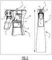
- Fig. 2 Part of the solution proposed by the invention is schematically shown in Fig. 2 .
- the so-called “shroud" - of the dispensing device 3 is formed as an integral part of the container or "bottle" 2, a stable fluid dispensing system 1 is obtained, where leakage in the neck area 16 of the container 2 is prevented. This is schematically represented by the straight or unbent arrow.
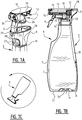
- the container 2 of the fluid dispensing system 1 comprises a flexible inner container or bag 4 and a form-retaining or stiff outer container 5 ( Fig. 3B ).
- the inner container may be made of a polyolefin, e.g. PE or PP, while the outer container 5 may be made of PET.
- Polyolefins have excellent chemical resistance and provide flexibility, while PET has good gas barrier properties and provides strength and stability, as well as an excellent finish.
- PET has good gas barrier properties and provides strength and stability, as well as an excellent finish.
- the inner and outer containers 4, 5 have complementary properties. It will be clear that other material may be selected for the inner and outer layers, depending on the intended use of the fluid dispensing system.
- the inner and outer containers 4, 5 are connected to each other at or near the neck 16.
- the inner and outer containers 4, 5 are further connected to each other at the bottom 17 of the container 2, e.g. in the way described in WO 2009/041809 A1 , the disclosure of which is incorporated herein by reference.
- This connection includes a protrusion 31 of the inner layer 24 which extends through the bottom 35 of the outer layer 25 of the preform 23.
- a space 18 between the inner and outer containers 4, 5 can be connected to the surrounding atmosphere by an opening 19.
- the opening 19 is formed in the bottom 17 near or around the connection between the inner and outer containers 4, 5.
- an opening could be formed in the neck area 16 or in any other part of the outer container 5. Since this opening allows ambient air to fill the space 18 whenever fluid is dispensed from the inner container 4, there is no need for any venting opening in fluid communication with the interior of the container, as is required in conventional containers. Thus a further potential source of leakage is eliminated.
- One of the layers of the container 2, i.e. either the inner container 4 or the outer container 5 extends beyond the neck area 16 to form the integrated part 6 of the housing and/or frame of the dispensing device 3.
- the inner container 4 made of PP, which extends and forms the shroud 36 of the dispensing device 3.
- the shroud 36 which from a functional point of view forms part of the dispensing device 3, is structurally integrated with the container 2.
- the part 7 of the dispensing device 3 that is not integrally moulded with the container 2 has a number of moving parts.
- the non-integrated part 7 of dispensing device 3 includes a one-piece body or frame 13 which includes a piston chamber 10 in which a piston 11 is arranged for reciprocating movement ( Fig. 9B ).
- the piston 11 is driven by a trigger 9 which is pivotably connected to the frame 13.
- Two biasing members 22 bias the trigger 9 to a standby position in which the piston 11 is in its extended position removed from an end wall of the piston chamber 10.
- the piston chamber 10 is connected to a fluid inlet 20, which can be connected to a dip tube 21 extending into the container 2.
- the piston chamber 10 is further connected to an outflow channel 14 that is formed in the frame 13.
- a precompression valve 12 e.g. a domed diaphragm valve as described in detail in WO 2008/116656 A1 , the disclosure of which is incorporated herein by reference, is arranged between the piston chamber 10 and the outflow channel 14.
- the precompression valve 12 is pretensioned by being arranged between the frame 13 and a wall 28 that has been integrally moulded with the shroud 36 and the container 2. This precompression valve 12 ensures that fluid is only dispensed when a predetermined pressure is reached in the piston chamber 10.
- the outflow channel 14 terminates in a nozzle 15 that converts the stream of pressurized fluid into a spray.
- the shroud 36 not only the shroud 36, but also the biasing members 22, which also form a functional part of the dispensing device 3, are integrally formed with the container 2. But while the shroud 36 is integrally formed with the inner container 4, the biasing members 22 are integrally formed with the outer container 5, i.e. the other of the two layers.
- the inner and outer containers 4, 5 are both formed by injection moulding followed by blow moulding. Injection moulding results in a preform 23 shaped like a test tube ( Fig. 4A , 5A, 5B ). This preform 23 has an inner layer 24 and an outer layer 25, which after blow moulding will form the inner container 4 and the outer container 5, respectively ( Fig. 4B , 6 ).
- the shroud 36 and the biasing member 22 are formed when the layers 24, 25 are injection moulded, and maintain their shape and dimensions during blow moulding.
- the inner and outer layers 24, 25 may be separately injection moulded and then connected, or they may be formed in a multi-component injection moulding process.
- the part 7 of the dispensing device 3 that is not integrally formed with the container 2 - in the illustrated embodiment the frame 13, trigger 9, piston 11 and nozzle 15 - is assembled with the container 2 - including the integrated part 6 of the housing, in this case the shroud 36, and the integrated biasing member 22 - by mechanical fastening.
- mechanical fastening can be contemplated, including snap-fitting by means of protrusions 34 on the frame 13 and recesses 33 in inside of the shroud 36 ( Fig. 7A ), screwing or connecting by a bayonet. All these fastening systems ensure excellent sealing between a lower edge 26 of the frame 13 and the neck 16 of the container 2.
- the nozzle 15 When the non-integrated part 7 of the dispensing device 3 is pressed onto the container 2 in the direction of the arrow, the nozzle 15 will be received in a recess 29 in the shroud 36, while the trigger 9 will protrude downwardly though an opening 30 in the shroud 36.
- the inlet 20 or dip tube 21 will always be in contact with the fluid, so that the fluid dispensing system 1 can be used in any possible orientation ( Fig. 7C ).
- the inlet 20 may be lengthened ( Fig. 8B ) or a dip tube 21 may be used ( Fig. 8A ), although such dip tube can be much shorter than dip tubes in conventional trigger sprayers, as will be discussed below.
- the dispensing device 3 of this fluid dispensing system 1 mainly differs from that of the first embodiment by the presence of a buffer 27.
- This buffer 27 serves to accommodate a surplus of fluid which has been pressurized in the piston chamber 10 but cannot pass the nozzle 15 at the rate at which it is supplied from the piston chamber 10.
- the piston chamber 10 is vertically arranged in the frame 13, rather than horizontally as in the previous embodiment. Consequently, the piston (not shown) also reciprocates in vertical direction.
- the precompression valve (not shown) is arranged between the outlet channel (which is not shown either but which also runs vertically) and the nozzle 15.
- the shroud 36 - of the dispensing device 3 is integrally formed with the container 2.
- the biasing members 22 are integrally formed with the trigger 9 and form part of the non-integrated portion 7 of the dispensing device 3.
- the shroud is integrally formed with the inner container 4, which again is made of PP, while the outer container 5 is made of PET.
- the inner and outer containers 4, 5 are again made by blow moulding inner and outer layers 24, 25 of a preform 23 ( Fig. 11, 12 ).
- the inner and outer layers 24, 25 are connected at or near the neck 16 of the preform 23 or container 2. They are further connected at or near the bottom 35 of the preform 23, which becomes part of the bottom 17 of the container 2 after blow moulding.
- a vent opening 19 is again arranged in the bottom 17 of the container 2.
- the shroud is made up of two parts, a first part 36 extending along approximately three quarters of the periphery of the dispensing system 1 and a second part 37 partially filling the gap left open by the first part 36.
- Two slots 38 are formed between the first and second shroud parts 36, 37. These slots 38 serve to accommodate edges 39 of the trigger 9 when the dispensing system 1 is in use and the trigger 9 is depressed.
- the second shroud part 37 also serves as a stop and as an additional biasing member acting on the trigger 9.
- the container 2 includes a recess 40 for accommodating a lower part of the trigger 9 when depressed, and also acts as a stop for limiting movement of the trigger.
- the neck 16 By integrating a part 6 (the shroud) of the housing and/or frame of the dispensing device 3 into the container 2, the neck 16 can be made smaller than in conventional trigger sprayers. This is due to the fact that the neck 16 only needs to form a seal with an edge 26 of the frame of the dispensing device 3 ( Fig. 13A ), but does not have to withstand any significant loads acting on the trigger sprayer or fluid dispensing device 1. Consequently, the non-integrated part 7 of the dispensing device 3 can be inserted further into the container 2, as indicated by the distance d.
- the entire fluid dispensing system 1 can be made more compact than the buffering trigger sprayer of WO 2013/043938 A2 , of which two variants are shown in Fig. 14A and Fig.
- the buffering trigger sprayer or fluid dispensing system 101 of WO 2013/043938 A2 which is marketed by the applicant under the trademark ImpressTM, has a dispensing device 103 which extends over a height h1 from a sealing edge 126 with the neck 116 of the container 102 ( Fig. 14A ).
- both the Impress and the Impress Mini dispensing systems rely on a connection between the container and the dispensing device that requires certain dimensions in order to ensure sufficient strength and stability.
- the invention allows the fluid dispensing system 1 to have a height h3 above the sealing edge 26 that is even smaller than that of the prior art Impress Mini buffering trigger sprayer.
- the non-integrated part 7 of the dispensing device 3 is assembled with the container 2 including the integrated part 6 by snap-fitting. And here again, venting into the space 18 between the inner and outer containers 4, 5 means that there is (substantially) no head of air, so that the fluid dispensing system 1 can be used in any desired orientation.
- the fluid dispensing system of the present invention and its method of manufacture present many advantages over conventional trigger sprayers and their method of manufacture, as illustrated in Fig. 15A and 15B and in Fig. 16A and 16B .
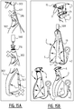
- Fig. 16 in the prior art misalignment of the (long) dip tube 321 when assembling and filling a fluid dispensing system 1 in a filling line was often a problem. Because the dip tube 321 had to extend all the way to the bottom of the container 302, it was relatively long. And since it also was relatively thin, it was flexible and not easy to direct into the neck 316 of the container 302 ( Fig. 15A at the top). As the fluid dispensing system 1 of the invention requires no dip tube or only a very limited length dip tube 21, this problem does not present itself anymore ( Fig. 15B at the top).
- FIG. 15A Another problem that arose when filling prior art containers 302 in a filling line was that due to the pressure at which the fluid was discharged from a filling spout 500, the fluid would start to foam ( Fig. 15A at the center). This foaming would lead to leakage and incomplete filling of the container 302.
- the container 2 of the present application is a double walled container having a space 18 between the inner container 4, which is to be filled with the fluid, and the outer container 5, foaming can be effectively suppressed. Pressurized air or another gas can be supplied to the space 18 by a pressure source 42, and the pressure in the space 18 will prevent the fluid being injected into the inner container 4 from foaming ( Fig. 15B at the center).
- the invention has been described by way of a number of exemplary embodiments, it will be clear that it is not limited to these embodiments.
- other parts of the housing and/or frame could be integrated with the container.
- parts of the housing and/or frame or moving parts of the dispensing device could be integrated with other layers of the double walled container than described and shown here.
- the double walled container is made by blow moulding a preform that has been made by injection moulding
- blow moulding could also be done on the basis of a double walled extrusion. In that case a part of the extrusion could be shaped e.g.
- the invention is not just applicable to trigger type fluid dispensers, but could be applied equally well to fluid dispensing systems which are operated by other types of actuators, such as pushbuttons or vertically movable levers.
- actuators such as pushbuttons or vertically movable levers.
- Such dispensing systems having vertically moveable actuators are often used for liquid soaps or lotions.
Landscapes
- Engineering & Computer Science (AREA)
- Manufacturing & Machinery (AREA)
- Mechanical Engineering (AREA)
- Containers And Packaging Bodies Having A Special Means To Remove Contents (AREA)
- Blow-Moulding Or Thermoforming Of Plastics Or The Like (AREA)
- Medical Preparation Storing Or Oral Administration Devices (AREA)
Claims (15)
- Système de distribution dosée d'un fluide, comprenant un contenant (2) pour le fluide et un dispositif de distribution (3) connecté à celui-ci, dans lequel le contenant (2) comprend un contenant externe (5) à conservation de forme et un contenant interne (4) souple connecté à celui-ci, dans lequel les contenants interne et externe (4, 5) sont mutuellement connectés à ou à proximité d'un col (16) du contenant (2), et
dans lequel un espace (18) à amener en communication fluidique avec l'atmosphère ambiante peut être développé entre les contenants interne et externe (4, 5),
caractérisé en ce que le dispositif de distribution (3) inclut un logement et/ou un cadre dont au moins une partie (6) est solidaire du contenant (2), dans lequel au moins un des contenants interne ou externe (4, 5) s'étend au-delà du col (16) pour former la partie (6) solidaire du logement et/ou du cadre du dispositif de distribution. - Système de distribution de fluide selon la revendication 1, dans lequel :la partie (6) solidaire du logement et/ou du cadre du dispositif de distribution est solidaire du contenant externe (5) ; oula partie (6) solidaire du logement et/ou du cadre du dispositif de distribution est solidaire du contenant interne (4).
- Système de distribution de fluide selon la revendication 1 ou 2, dans lequel une partie non solidaire (7) du dispositif de distribution (3) est fixée mécaniquement à la partie (6) du logement et/ou du cadre qui est solidaire du contenant (2).
- Système de distribution de fluide selon l'une quelconque des revendications précédentes, dans lequel le contenant externe (5) comprend du PET et le contenant interne (4) comprend une polyoléfine, en particulier du PE ou du PP.
- Système de distribution de fluide selon l'une quelconque des revendications précédentes, dans lequel le dispositif de distribution (3) comprend des parties mobiles, dont au moins une (22) est solidaire du contenant, facultativement dans lequel la partie mobile (22) est solidaire d'un du contenant interne (4) et du contenant externe (5) et la partie (6) du logement et/ou du cadre est solidaire de l'autre du contenant interne et externe (4, 5).
- Système de distribution de fluide selon la revendication 4 combinée à la revendication 5, dans lequel la partie mobile (22) comprend un élément de sollicitation qui est solidaire du contenant externe (5) tandis que la partie (6) du logement et/ou du cadre est solidaire du contenant interne.
- Système de distribution de fluide selon l'une quelconque des revendications précédentes, dans lequel le contenant est formé par :moulage par injection suivi par moulage par soufflage ; oucoextrusion suivie par moulage par soufflage.
- Procédé de fabrication d'un système de distribution dosée d'un fluide, comprenant les étapes de :- fabrication d'un contenant (2) pour le fluide, ledit contenant (2) comprenant un contenant externe (5) à conservation de forme et un contenant interne (4) souple connecté avec celui-ci, dans lequel la fabrication du contenant comprend la connexion mutuelle des contenants interne et externe (4, 5) à ou à proximité d'un col (16) du contenant ;- fabrication d'un dispositif de distribution (3) comprenant un logement et/ou un cadre ; et- assemblage du contenant (2) et du dispositif de distribution (3) ;caractérisé en ce que :au moins une partie (6) du logement et/ou du cadre du dispositif de distribution (3) est solidaire du contenant (2) ;la fabrication du contenant (2) comprend la formation d'au moins un des contenants interne ou externe (4, 5) de sorte qu'il s'étende au-delà du col (16) pour constituer la partie (6) solidaire du logement et/ou du cadre du dispositif de distribution (3) ; etl'assemblage du contenant (2) et du dispositif de distribution (3) comprend le montage d'une partie non solidaire (7) du dispositif de distribution (3) dans la partie (6) du logement et/ou du cadre du dispositif de distribution qui est solidaire du contenant (2).
- Procédé selon la revendication 8, dans lequel pendant la fabrication du contenant (2) :la partie (6) solidaire du logement et/ou du cadre du dispositif de distribution est solidaire du contenant externe (5) ; oula partie (6) solidaire du logement et/ou du cadre du dispositif de distribution est solidaire du contenant interne (4).
- Procédé selon la revendication 8 ou 9, dans lequel l'assemblage du contenant (2) et du dispositif de distribution (3) comprend la fixation mécanique de la partie non solidaire (7) du dispositif de distribution (3) à la partie (6) du logement et/ou du cadre qui est solidaire du contenant (2).
- Procédé selon l'une quelconque des revendications 8 à 10, dans lequel la fabrication du contenant (2) comprend la fabrication du contenant externe (5) à partir d'un matériau comprenant du PET et la fabrication du contenant interne (4) à partir d'un matériau comprenant une polyoléfine, en particulier du PE ou du PP.
- Procédé selon l'une quelconque des revendications 8 à 11, dans lequel :le dispositif de distribution (3) comprend des parties mobiles ;la fabrication du contenant (2) comprend la formation de manière solidaire d'au moins une (22) des parties mobiles ; etl'assemblage du contenant (2) et du dispositif de distribution (3) comprend la mise en prise de la partie mobile (22) solidaire avec la partie non solidaire (7) du dispositif de distribution (3) ;facultativement dans lequel :
la fabrication du contenant (2) comprend la formation de manière solidaire de la partie mobile (22) avec un du contenant interne (4) et du contenant externe (5) et la formation de manière solidaire de la partie (6) du logement et/ou du cadre avec l'autre du contenant interne et externe (4, 5). - Procédé selon la revendication 11 combinée à la revendication 12, dans lequel
la fabrication du contenant (2) comprend la formation de manière solidaire du contenant externe (5) d'un élément de sollicitation (22) qui constitue la partie mobile et la formation de manière solidaire du contenant interne (4) de la partie (6) du logement et/ou du cadre. - Procédé selon l'une quelconque des revendications 8 à 13, dans lequel la fabrication du contenant (2) comprend le moulage par injection d'une préforme (23) du contenant, puis le moulage par soufflage de la préforme (23) dans le contenant (2) ;
facultativement dans lequel la préforme (23) inclut une couche interne (24) et une couche externe (25) et dans lequel le moulage par injection de la préforme (23) inclut :le moulage par injection d'une des couches interne et externe (24, 25), puis le moulage par injection de l'autre des couches interne et externe (24, 25) dans deux étapes successives dans un processus de moulage par injection de plusieurs composants ; oule moulage par injection des couches interne et externe (24, 25) dans des processus de moulage par injection distincts et dans lequel les couches interne et externe (24, 25) sont assemblées après ledit moulage par injection. - Procédé selon l'une quelconque des revendications 8 à 13, dans lequel la fabrication du contenant (2) comprend la coextrusion d'un tube multicouche, puis le moulage par soufflage du tube multicouche dans le contenant (2).
Priority Applications (1)
| Application Number | Priority Date | Filing Date | Title |
|---|---|---|---|
| PL16738409T PL3319734T3 (pl) | 2015-07-09 | 2016-07-11 | Układ do dozowania porcji płynu i sposób jego wytwarzania |
Applications Claiming Priority (2)
| Application Number | Priority Date | Filing Date | Title |
|---|---|---|---|
| EP15176166 | 2015-07-09 | ||
| PCT/EP2016/066455 WO2017005938A1 (fr) | 2015-07-09 | 2016-07-11 | Système de distribution mesurée d'un liquide et procédé de fabrication |
Publications (2)
| Publication Number | Publication Date |
|---|---|
| EP3319734A1 EP3319734A1 (fr) | 2018-05-16 |
| EP3319734B1 true EP3319734B1 (fr) | 2020-04-22 |
Family
ID=53723999
Family Applications (1)
| Application Number | Title | Priority Date | Filing Date |
|---|---|---|---|
| EP16738409.8A Active EP3319734B1 (fr) | 2015-07-09 | 2016-07-11 | System de distribution dosée d'un liquide et methode de fabrication |
Country Status (13)
| Country | Link |
|---|---|
| US (2) | US11141749B2 (fr) |
| EP (1) | EP3319734B1 (fr) |
| JP (1) | JP6860270B2 (fr) |
| KR (1) | KR102932903B1 (fr) |
| CN (1) | CN108025322B (fr) |
| AU (1) | AU2016289525B2 (fr) |
| BR (1) | BR112018000455B1 (fr) |
| ES (1) | ES2800034T3 (fr) |
| MX (1) | MX2018000015A (fr) |
| PL (1) | PL3319734T3 (fr) |
| RU (1) | RU2734519C2 (fr) |
| WO (1) | WO2017005938A1 (fr) |
| ZA (1) | ZA201800128B (fr) |
Families Citing this family (13)
| Publication number | Priority date | Publication date | Assignee | Title |
|---|---|---|---|---|
| AU2016289525B2 (en) | 2015-07-09 | 2022-02-03 | Dispensing Technologies B.V. | System for dosed dispensing of a fluid and method of manufacturing |
| EP3618970A1 (fr) * | 2017-05-01 | 2020-03-11 | Dispensing Technologies B.V. | Dispositif, système et procédé de distribution d'un liquide a partir d'un contenant |
| CN111787951B (zh) * | 2018-03-01 | 2025-06-17 | Igm生物科学股份有限公司 | 影响IgM血清半衰期的IgM Fc和J链突变 |
| CN111438020B (zh) * | 2020-04-22 | 2024-09-13 | 青岛汉柏塑料科技有限公司 | 贮存杯以及喷枪液体贮存器 |
| DE102020007396A1 (de) | 2020-12-04 | 2022-06-09 | Aptar Dortmund Gmbh | Abgabeeinrichtung und Spender |
| EP4008442B1 (fr) | 2020-12-04 | 2024-07-17 | Aptar Dortmund GmbH | Agencement de distribution et distributeur |
| JP7745481B2 (ja) * | 2022-02-28 | 2025-09-29 | 株式会社吉野工業所 | トリガー式液体噴出器 |
| NL2034393B1 (en) * | 2023-03-21 | 2024-09-30 | Dispensing Tech Bv | Device and system for dispensing a liquid |
| NL2036667B1 (en) * | 2023-12-24 | 2025-07-09 | Dispensing Tech Bv | Device and system for dispensing a liquid |
| WO2025018884A1 (fr) * | 2023-07-15 | 2025-01-23 | Dispensing Technologies B.V. | Dispositif et système de distribution d'un liquide |
| WO2025114616A1 (fr) * | 2023-12-01 | 2025-06-05 | Dispensing Technologies B.V. | Dispositif et système de distribution de liquide |
| NL2036668B1 (en) * | 2023-12-24 | 2025-07-09 | Dispensing Tech Bv | Device and system for dispensing a liquid |
| NL2036669B1 (en) * | 2023-12-24 | 2025-07-09 | Dispensing Tech Bv | Device and system for dispensing a liquid |
Family Cites Families (24)
| Publication number | Priority date | Publication date | Assignee | Title |
|---|---|---|---|---|
| DE4139555A1 (de) * | 1991-09-18 | 1993-03-25 | Gaplast Gmbh | Behaelter |
| US5927566A (en) * | 1996-07-11 | 1999-07-27 | Aptargroup, Inc. | One-piece dispensing system and method for making same |
| CA2230768C (fr) * | 1997-02-28 | 2007-02-13 | John W. Safian | Contenant multicouche |
| FR2820121B1 (fr) * | 2001-01-30 | 2003-06-13 | Oreal | Flacon pompe a utilisation multidirectionnelle |
| US20050127107A1 (en) | 2001-09-21 | 2005-06-16 | Pierre Mbonyumuhire | Dosing device with a medium reservoir and a pump device |
| FR2833577B1 (fr) * | 2001-12-14 | 2004-03-12 | Lablabo | Dispositif a recipient rigide et poches multiples souples pour le conditionnement et la distribution de fluides |
| FR2864045B1 (fr) * | 2003-12-22 | 2006-03-31 | Valois Sas | Organe de distribution de produit fluide. |
| FR2866321B1 (fr) * | 2004-02-13 | 2007-05-18 | Lablabo | Poche souple deformable et dispositif pour le conditionnement et la distribution de produits fluides. |
| RU2008142552A (ru) * | 2006-03-28 | 2010-05-10 | Оцука Фармасьютикал Ко., Лтд. (Jp) | Контейнер для подачи жидкости и контейнер для глазных капель |
| EP2517797B1 (fr) | 2007-03-24 | 2020-05-27 | Afa Polytek B.V. | Système de précompression pour dispositif de distribution de liquides et procédé d'assemblage d'un tel système de précompression |
| GB0715224D0 (en) | 2007-08-02 | 2007-09-12 | Leafgreen Ltd | Manual pump type fluid dispenser and a method of manufacturing such a dispenser |
| CN101873978B (zh) | 2007-09-22 | 2013-03-06 | 分配技术有限公司 | 具有可变形内部容器的容器及其制造方法 |
| NL1035761C2 (nl) * | 2008-07-28 | 2010-02-05 | Dispensing Technologies Bv | Werkwijze en inrichting voor het gedoseerd afgeven van een vloeistof uit een houder. |
| NL1036085C (nl) * | 2008-10-17 | 2010-04-20 | Dispensing Technologies Bv | Werkwijze en inrichting voor het afgeven van een product. |
| IT1394925B1 (it) * | 2009-04-30 | 2012-07-27 | Patrini | Metodo per la realizzazione di un contenitore associabile a pompe airless |
| BR112012011566A2 (pt) | 2009-10-09 | 2016-06-28 | Py Daniel C | dispositivo com fecho co-moldado, válvulas de sentido único, câmara de armazenamento de volume variável e método relacionado |
| IT1401659B1 (it) * | 2010-09-16 | 2013-08-02 | Guala Dispensing Spa | Dispositivo di erogazione per liquidi |
| IT1402728B1 (it) * | 2010-11-22 | 2013-09-18 | Guala Dispensing Spa | Dispositivo di erogazione a grilletto |
| FR2973785B1 (fr) | 2011-04-07 | 2014-07-18 | Valois Sas | Distributeur de produit fluide et procede de fabrication d'un tel distributeur. |
| AU2012312279B2 (en) | 2011-09-20 | 2017-10-19 | Dispensing Technologies B.V. | Metered and active sprayer devices with aerosol functionality ("Flairosol II") |
| JP5882843B2 (ja) | 2012-06-21 | 2016-03-09 | 矢崎総業株式会社 | コネクタ、及び充填材の注入方法 |
| JP5996355B2 (ja) * | 2012-09-28 | 2016-09-21 | 株式会社吉野工業所 | 二重容器、その容器用プリフォーム、及びその容器の製造方法 |
| JP6011929B2 (ja) * | 2012-10-31 | 2016-10-25 | 株式会社吉野工業所 | 2軸延伸ブロー成形容器及びその製造方法 |
| AU2016289525B2 (en) | 2015-07-09 | 2022-02-03 | Dispensing Technologies B.V. | System for dosed dispensing of a fluid and method of manufacturing |
-
2016
- 2016-07-11 AU AU2016289525A patent/AU2016289525B2/en active Active
- 2016-07-11 KR KR1020187003990A patent/KR102932903B1/ko active Active
- 2016-07-11 CN CN201680040455.3A patent/CN108025322B/zh active Active
- 2016-07-11 EP EP16738409.8A patent/EP3319734B1/fr active Active
- 2016-07-11 JP JP2017567606A patent/JP6860270B2/ja active Active
- 2016-07-11 BR BR112018000455-3A patent/BR112018000455B1/pt active IP Right Grant
- 2016-07-11 WO PCT/EP2016/066455 patent/WO2017005938A1/fr not_active Ceased
- 2016-07-11 MX MX2018000015A patent/MX2018000015A/es unknown
- 2016-07-11 US US15/742,105 patent/US11141749B2/en active Active
- 2016-07-11 PL PL16738409T patent/PL3319734T3/pl unknown
- 2016-07-11 ES ES16738409T patent/ES2800034T3/es active Active
- 2016-07-11 RU RU2018104847A patent/RU2734519C2/ru active
-
2018
- 2018-01-08 ZA ZA2018/00128A patent/ZA201800128B/en unknown
-
2021
- 2021-09-03 US US17/467,064 patent/US11833534B2/en active Active
Non-Patent Citations (1)
| Title |
|---|
| None * |
Also Published As
| Publication number | Publication date |
|---|---|
| CN108025322A (zh) | 2018-05-11 |
| PL3319734T3 (pl) | 2020-09-21 |
| KR102932903B1 (ko) | 2026-02-27 |
| EP3319734A1 (fr) | 2018-05-16 |
| RU2018104847A (ru) | 2019-08-09 |
| AU2016289525B2 (en) | 2022-02-03 |
| KR20180040150A (ko) | 2018-04-19 |
| AU2016289525A1 (en) | 2018-02-22 |
| US20220126313A1 (en) | 2022-04-28 |
| BR112018000455A2 (pt) | 2018-09-11 |
| CN108025322B (zh) | 2021-04-13 |
| US11141749B2 (en) | 2021-10-12 |
| RU2734519C2 (ru) | 2020-10-19 |
| US20180193857A1 (en) | 2018-07-12 |
| JP2018520954A (ja) | 2018-08-02 |
| MX2018000015A (es) | 2018-06-20 |
| WO2017005938A1 (fr) | 2017-01-12 |
| ZA201800128B (en) | 2022-11-30 |
| BR112018000455B1 (pt) | 2021-10-19 |
| ES2800034T3 (es) | 2020-12-23 |
| JP6860270B2 (ja) | 2021-04-14 |
| RU2018104847A3 (fr) | 2019-08-27 |
| US11833534B2 (en) | 2023-12-05 |
Similar Documents
| Publication | Publication Date | Title |
|---|---|---|
| US11833534B2 (en) | System for dosed dispensing of a fluid and method of manufacturing such fluid dispensing system | |
| US11406996B2 (en) | Dip tube connectors and pump systems using the same | |
| US10174884B2 (en) | Valve stem for a compressible valve | |
| US20220184650A1 (en) | Recyclable pump dispenser | |
| EP2655893B1 (fr) | Dispositifs de pompe | |
| US20150108387A1 (en) | Compressible valve for a pressurized container | |
| US20110024452A1 (en) | Container associable with airless pumps and method for its production | |
| US20140144945A1 (en) | Dispenser pump button | |
| JP2009508774A (ja) | 形状維持容器から製造物を分配する方法及びアッセンブリ | |
| AU2016281711A1 (en) | Compressible valve and actuator for a pressurized container | |
| AU2016282798A1 (en) | Compressible valve for a pressurized container | |
| US10486892B1 (en) | Packages and arrays of packages for plastic aerosol dispensers | |
| US10618072B2 (en) | Inline vacuum spring sustained duration sprayer | |
| WO2022127908A1 (fr) | Ensemble récipient et système de stockage et de distribution le comprenant | |
| EP1144120B1 (fr) | Distributeur destine a un recipient et procede de fabrication et de remplissage de ce recipient au moyen d'une tete de dosage et/ou de remplissage | |
| US11691166B2 (en) | Trigger sprayer venting systems and methods for using the same | |
| WO2006111368A2 (fr) | Distributeur d'aerosol multirecipient et son procede de production | |
| US20160296958A1 (en) | Liquid dispenser with pump |
Legal Events
| Date | Code | Title | Description |
|---|---|---|---|
| STAA | Information on the status of an ep patent application or granted ep patent |
Free format text: STATUS: THE INTERNATIONAL PUBLICATION HAS BEEN MADE |
|
| PUAI | Public reference made under article 153(3) epc to a published international application that has entered the european phase |
Free format text: ORIGINAL CODE: 0009012 |
|
| STAA | Information on the status of an ep patent application or granted ep patent |
Free format text: STATUS: REQUEST FOR EXAMINATION WAS MADE |
|
| 17P | Request for examination filed |
Effective date: 20180117 |
|
| AK | Designated contracting states |
Kind code of ref document: A1 Designated state(s): AL AT BE BG CH CY CZ DE DK EE ES FI FR GB GR HR HU IE IS IT LI LT LU LV MC MK MT NL NO PL PT RO RS SE SI SK SM TR |
|
| AX | Request for extension of the european patent |
Extension state: BA ME |
|
| DAV | Request for validation of the european patent (deleted) | ||
| DAX | Request for extension of the european patent (deleted) | ||
| GRAP | Despatch of communication of intention to grant a patent |
Free format text: ORIGINAL CODE: EPIDOSNIGR1 |
|
| STAA | Information on the status of an ep patent application or granted ep patent |
Free format text: STATUS: GRANT OF PATENT IS INTENDED |
|
| INTG | Intention to grant announced |
Effective date: 20191111 |
|
| GRAS | Grant fee paid |
Free format text: ORIGINAL CODE: EPIDOSNIGR3 |
|
| GRAA | (expected) grant |
Free format text: ORIGINAL CODE: 0009210 |
|
| STAA | Information on the status of an ep patent application or granted ep patent |
Free format text: STATUS: THE PATENT HAS BEEN GRANTED |
|
| AK | Designated contracting states |
Kind code of ref document: B1 Designated state(s): AL AT BE BG CH CY CZ DE DK EE ES FI FR GB GR HR HU IE IS IT LI LT LU LV MC MK MT NL NO PL PT RO RS SE SI SK SM TR |
|
| REG | Reference to a national code |
Ref country code: CH Ref legal event code: EP |
|
| REG | Reference to a national code |
Ref country code: IE Ref legal event code: FG4D |
|
| REG | Reference to a national code |
Ref country code: DE Ref legal event code: R096 Ref document number: 602016034553 Country of ref document: DE |
|
| REG | Reference to a national code |
Ref country code: AT Ref legal event code: REF Ref document number: 1259384 Country of ref document: AT Kind code of ref document: T Effective date: 20200515 |
|
| REG | Reference to a national code |
Ref country code: NL Ref legal event code: FP |
|
| REG | Reference to a national code |
Ref country code: LT Ref legal event code: MG4D |
|
| PG25 | Lapsed in a contracting state [announced via postgrant information from national office to epo] |
Ref country code: SE Free format text: LAPSE BECAUSE OF FAILURE TO SUBMIT A TRANSLATION OF THE DESCRIPTION OR TO PAY THE FEE WITHIN THE PRESCRIBED TIME-LIMIT Effective date: 20200422 Ref country code: LT Free format text: LAPSE BECAUSE OF FAILURE TO SUBMIT A TRANSLATION OF THE DESCRIPTION OR TO PAY THE FEE WITHIN THE PRESCRIBED TIME-LIMIT Effective date: 20200422 Ref country code: NO Free format text: LAPSE BECAUSE OF FAILURE TO SUBMIT A TRANSLATION OF THE DESCRIPTION OR TO PAY THE FEE WITHIN THE PRESCRIBED TIME-LIMIT Effective date: 20200722 Ref country code: GR Free format text: LAPSE BECAUSE OF FAILURE TO SUBMIT A TRANSLATION OF THE DESCRIPTION OR TO PAY THE FEE WITHIN THE PRESCRIBED TIME-LIMIT Effective date: 20200723 Ref country code: IS Free format text: LAPSE BECAUSE OF FAILURE TO SUBMIT A TRANSLATION OF THE DESCRIPTION OR TO PAY THE FEE WITHIN THE PRESCRIBED TIME-LIMIT Effective date: 20200822 Ref country code: FI Free format text: LAPSE BECAUSE OF FAILURE TO SUBMIT A TRANSLATION OF THE DESCRIPTION OR TO PAY THE FEE WITHIN THE PRESCRIBED TIME-LIMIT Effective date: 20200422 Ref country code: PT Free format text: LAPSE BECAUSE OF FAILURE TO SUBMIT A TRANSLATION OF THE DESCRIPTION OR TO PAY THE FEE WITHIN THE PRESCRIBED TIME-LIMIT Effective date: 20200824 |
|
| REG | Reference to a national code |
Ref country code: AT Ref legal event code: MK05 Ref document number: 1259384 Country of ref document: AT Kind code of ref document: T Effective date: 20200422 |
|
| PG25 | Lapsed in a contracting state [announced via postgrant information from national office to epo] |
Ref country code: LV Free format text: LAPSE BECAUSE OF FAILURE TO SUBMIT A TRANSLATION OF THE DESCRIPTION OR TO PAY THE FEE WITHIN THE PRESCRIBED TIME-LIMIT Effective date: 20200422 Ref country code: RS Free format text: LAPSE BECAUSE OF FAILURE TO SUBMIT A TRANSLATION OF THE DESCRIPTION OR TO PAY THE FEE WITHIN THE PRESCRIBED TIME-LIMIT Effective date: 20200422 Ref country code: HR Free format text: LAPSE BECAUSE OF FAILURE TO SUBMIT A TRANSLATION OF THE DESCRIPTION OR TO PAY THE FEE WITHIN THE PRESCRIBED TIME-LIMIT Effective date: 20200422 Ref country code: BG Free format text: LAPSE BECAUSE OF FAILURE TO SUBMIT A TRANSLATION OF THE DESCRIPTION OR TO PAY THE FEE WITHIN THE PRESCRIBED TIME-LIMIT Effective date: 20200722 |
|
| REG | Reference to a national code |
Ref country code: ES Ref legal event code: FG2A Ref document number: 2800034 Country of ref document: ES Kind code of ref document: T3 Effective date: 20201223 |
|
| PG25 | Lapsed in a contracting state [announced via postgrant information from national office to epo] |
Ref country code: AL Free format text: LAPSE BECAUSE OF FAILURE TO SUBMIT A TRANSLATION OF THE DESCRIPTION OR TO PAY THE FEE WITHIN THE PRESCRIBED TIME-LIMIT Effective date: 20200422 |
|
| REG | Reference to a national code |
Ref country code: DE Ref legal event code: R097 Ref document number: 602016034553 Country of ref document: DE |
|
| PG25 | Lapsed in a contracting state [announced via postgrant information from national office to epo] |
Ref country code: RO Free format text: LAPSE BECAUSE OF FAILURE TO SUBMIT A TRANSLATION OF THE DESCRIPTION OR TO PAY THE FEE WITHIN THE PRESCRIBED TIME-LIMIT Effective date: 20200422 Ref country code: CZ Free format text: LAPSE BECAUSE OF FAILURE TO SUBMIT A TRANSLATION OF THE DESCRIPTION OR TO PAY THE FEE WITHIN THE PRESCRIBED TIME-LIMIT Effective date: 20200422 Ref country code: AT Free format text: LAPSE BECAUSE OF FAILURE TO SUBMIT A TRANSLATION OF THE DESCRIPTION OR TO PAY THE FEE WITHIN THE PRESCRIBED TIME-LIMIT Effective date: 20200422 Ref country code: DK Free format text: LAPSE BECAUSE OF FAILURE TO SUBMIT A TRANSLATION OF THE DESCRIPTION OR TO PAY THE FEE WITHIN THE PRESCRIBED TIME-LIMIT Effective date: 20200422 Ref country code: EE Free format text: LAPSE BECAUSE OF FAILURE TO SUBMIT A TRANSLATION OF THE DESCRIPTION OR TO PAY THE FEE WITHIN THE PRESCRIBED TIME-LIMIT Effective date: 20200422 Ref country code: SM Free format text: LAPSE BECAUSE OF FAILURE TO SUBMIT A TRANSLATION OF THE DESCRIPTION OR TO PAY THE FEE WITHIN THE PRESCRIBED TIME-LIMIT Effective date: 20200422 |
|
| PG25 | Lapsed in a contracting state [announced via postgrant information from national office to epo] |
Ref country code: SK Free format text: LAPSE BECAUSE OF FAILURE TO SUBMIT A TRANSLATION OF THE DESCRIPTION OR TO PAY THE FEE WITHIN THE PRESCRIBED TIME-LIMIT Effective date: 20200422 Ref country code: MC Free format text: LAPSE BECAUSE OF FAILURE TO SUBMIT A TRANSLATION OF THE DESCRIPTION OR TO PAY THE FEE WITHIN THE PRESCRIBED TIME-LIMIT Effective date: 20200422 |
|
| PLBE | No opposition filed within time limit |
Free format text: ORIGINAL CODE: 0009261 |
|
| REG | Reference to a national code |
Ref country code: CH Ref legal event code: PL |
|
| STAA | Information on the status of an ep patent application or granted ep patent |
Free format text: STATUS: NO OPPOSITION FILED WITHIN TIME LIMIT |
|
| 26N | No opposition filed |
Effective date: 20210125 |
|
| REG | Reference to a national code |
Ref country code: BE Ref legal event code: MM Effective date: 20200731 |
|
| PG25 | Lapsed in a contracting state [announced via postgrant information from national office to epo] |
Ref country code: LU Free format text: LAPSE BECAUSE OF NON-PAYMENT OF DUE FEES Effective date: 20200711 Ref country code: LI Free format text: LAPSE BECAUSE OF NON-PAYMENT OF DUE FEES Effective date: 20200731 Ref country code: CH Free format text: LAPSE BECAUSE OF NON-PAYMENT OF DUE FEES Effective date: 20200731 |
|
| PG25 | Lapsed in a contracting state [announced via postgrant information from national office to epo] |
Ref country code: BE Free format text: LAPSE BECAUSE OF NON-PAYMENT OF DUE FEES Effective date: 20200731 Ref country code: SI Free format text: LAPSE BECAUSE OF FAILURE TO SUBMIT A TRANSLATION OF THE DESCRIPTION OR TO PAY THE FEE WITHIN THE PRESCRIBED TIME-LIMIT Effective date: 20200422 |
|
| PG25 | Lapsed in a contracting state [announced via postgrant information from national office to epo] |
Ref country code: IE Free format text: LAPSE BECAUSE OF NON-PAYMENT OF DUE FEES Effective date: 20200711 |
|
| PG25 | Lapsed in a contracting state [announced via postgrant information from national office to epo] |
Ref country code: TR Free format text: LAPSE BECAUSE OF FAILURE TO SUBMIT A TRANSLATION OF THE DESCRIPTION OR TO PAY THE FEE WITHIN THE PRESCRIBED TIME-LIMIT Effective date: 20200422 Ref country code: MT Free format text: LAPSE BECAUSE OF FAILURE TO SUBMIT A TRANSLATION OF THE DESCRIPTION OR TO PAY THE FEE WITHIN THE PRESCRIBED TIME-LIMIT Effective date: 20200422 Ref country code: CY Free format text: LAPSE BECAUSE OF FAILURE TO SUBMIT A TRANSLATION OF THE DESCRIPTION OR TO PAY THE FEE WITHIN THE PRESCRIBED TIME-LIMIT Effective date: 20200422 |
|
| PG25 | Lapsed in a contracting state [announced via postgrant information from national office to epo] |
Ref country code: MK Free format text: LAPSE BECAUSE OF FAILURE TO SUBMIT A TRANSLATION OF THE DESCRIPTION OR TO PAY THE FEE WITHIN THE PRESCRIBED TIME-LIMIT Effective date: 20200422 |
|
| REG | Reference to a national code |
Ref country code: NL Ref legal event code: RC Free format text: DETAILS LICENCE OR PLEDGE: RIGHT OF PLEDGE, ESTABLISHED Name of requester: ABN AMRO BANK N.V. Effective date: 20221115 |
|
| P01 | Opt-out of the competence of the unified patent court (upc) registered |
Effective date: 20230526 |
|
| PGFP | Annual fee paid to national office [announced via postgrant information from national office to epo] |
Ref country code: PL Payment date: 20250618 Year of fee payment: 10 |
|
| PGFP | Annual fee paid to national office [announced via postgrant information from national office to epo] |
Ref country code: NL Payment date: 20250726 Year of fee payment: 10 |
|
| PGFP | Annual fee paid to national office [announced via postgrant information from national office to epo] |
Ref country code: ES Payment date: 20250801 Year of fee payment: 10 |
|
| PGFP | Annual fee paid to national office [announced via postgrant information from national office to epo] |
Ref country code: DE Payment date: 20250729 Year of fee payment: 10 |
|
| PGFP | Annual fee paid to national office [announced via postgrant information from national office to epo] |
Ref country code: IT Payment date: 20250721 Year of fee payment: 10 |
|
| PGFP | Annual fee paid to national office [announced via postgrant information from national office to epo] |
Ref country code: GB Payment date: 20250728 Year of fee payment: 10 |
|
| PGFP | Annual fee paid to national office [announced via postgrant information from national office to epo] |
Ref country code: FR Payment date: 20250725 Year of fee payment: 10 |