EP3319783B1 - Verbinden von objekten - Google Patents
Verbinden von objekten Download PDFInfo
- Publication number
- EP3319783B1 EP3319783B1 EP16738092.2A EP16738092A EP3319783B1 EP 3319783 B1 EP3319783 B1 EP 3319783B1 EP 16738092 A EP16738092 A EP 16738092A EP 3319783 B1 EP3319783 B1 EP 3319783B1
- Authority
- EP
- European Patent Office
- Prior art keywords
- profile body
- embedding
- objects
- portions
- anchoring
- Prior art date
- Legal status (The legal status is an assumption and is not a legal conclusion. Google has not performed a legal analysis and makes no representation as to the accuracy of the status listed.)
- Active
Links
Images

Classifications
-
- B—PERFORMING OPERATIONS; TRANSPORTING
- B29—WORKING OF PLASTICS; WORKING OF SUBSTANCES IN A PLASTIC STATE IN GENERAL
- B29C—SHAPING OR JOINING OF PLASTICS; SHAPING OF MATERIAL IN A PLASTIC STATE, NOT OTHERWISE PROVIDED FOR; AFTER-TREATMENT OF THE SHAPED PRODUCTS, e.g. REPAIRING
- B29C65/00—Joining or sealing of preformed parts, e.g. welding of plastics materials; Apparatus therefor
- B29C65/02—Joining or sealing of preformed parts, e.g. welding of plastics materials; Apparatus therefor by heating, with or without pressure
- B29C65/08—Joining or sealing of preformed parts, e.g. welding of plastics materials; Apparatus therefor by heating, with or without pressure using ultrasonic vibrations
-
- B—PERFORMING OPERATIONS; TRANSPORTING
- B29—WORKING OF PLASTICS; WORKING OF SUBSTANCES IN A PLASTIC STATE IN GENERAL
- B29C—SHAPING OR JOINING OF PLASTICS; SHAPING OF MATERIAL IN A PLASTIC STATE, NOT OTHERWISE PROVIDED FOR; AFTER-TREATMENT OF THE SHAPED PRODUCTS, e.g. REPAIRING
- B29C65/00—Joining or sealing of preformed parts, e.g. welding of plastics materials; Apparatus therefor
- B29C65/56—Joining or sealing of preformed parts, e.g. welding of plastics materials; Apparatus therefor using mechanical means or mechanical connections, e.g. form-fits
- B29C65/562—Joining or sealing of preformed parts, e.g. welding of plastics materials; Apparatus therefor using mechanical means or mechanical connections, e.g. form-fits using extra joining elements, i.e. which are not integral with the parts to be joined
- B29C65/564—Joining or sealing of preformed parts, e.g. welding of plastics materials; Apparatus therefor using mechanical means or mechanical connections, e.g. form-fits using extra joining elements, i.e. which are not integral with the parts to be joined hidden in the joint, e.g. dowels or Z-pins
-
- B—PERFORMING OPERATIONS; TRANSPORTING
- B29—WORKING OF PLASTICS; WORKING OF SUBSTANCES IN A PLASTIC STATE IN GENERAL
- B29C—SHAPING OR JOINING OF PLASTICS; SHAPING OF MATERIAL IN A PLASTIC STATE, NOT OTHERWISE PROVIDED FOR; AFTER-TREATMENT OF THE SHAPED PRODUCTS, e.g. REPAIRING
- B29C65/00—Joining or sealing of preformed parts, e.g. welding of plastics materials; Apparatus therefor
- B29C65/56—Joining or sealing of preformed parts, e.g. welding of plastics materials; Apparatus therefor using mechanical means or mechanical connections, e.g. form-fits
- B29C65/567—Joining or sealing of preformed parts, e.g. welding of plastics materials; Apparatus therefor using mechanical means or mechanical connections, e.g. form-fits using a tamping or a swaging operation, i.e. at least partially deforming the edge or the rim of a first part to be joined to clamp a second part to be joined
- B29C65/568—Joining or sealing of preformed parts, e.g. welding of plastics materials; Apparatus therefor using mechanical means or mechanical connections, e.g. form-fits using a tamping or a swaging operation, i.e. at least partially deforming the edge or the rim of a first part to be joined to clamp a second part to be joined using a swaging operation, i.e. totally deforming the edge or the rim of a first part to be joined to clamp a second part to be joined
-
- B—PERFORMING OPERATIONS; TRANSPORTING
- B29—WORKING OF PLASTICS; WORKING OF SUBSTANCES IN A PLASTIC STATE IN GENERAL
- B29C—SHAPING OR JOINING OF PLASTICS; SHAPING OF MATERIAL IN A PLASTIC STATE, NOT OTHERWISE PROVIDED FOR; AFTER-TREATMENT OF THE SHAPED PRODUCTS, e.g. REPAIRING
- B29C65/00—Joining or sealing of preformed parts, e.g. welding of plastics materials; Apparatus therefor
- B29C65/56—Joining or sealing of preformed parts, e.g. welding of plastics materials; Apparatus therefor using mechanical means or mechanical connections, e.g. form-fits
- B29C65/64—Joining a non-plastics element to a plastics element, e.g. by force
- B29C65/645—Joining a non-plastics element to a plastics element, e.g. by force using friction or ultrasonic vibrations
-
- B—PERFORMING OPERATIONS; TRANSPORTING
- B29—WORKING OF PLASTICS; WORKING OF SUBSTANCES IN A PLASTIC STATE IN GENERAL
- B29C—SHAPING OR JOINING OF PLASTICS; SHAPING OF MATERIAL IN A PLASTIC STATE, NOT OTHERWISE PROVIDED FOR; AFTER-TREATMENT OF THE SHAPED PRODUCTS, e.g. REPAIRING
- B29C66/00—General aspects of processes or apparatus for joining preformed parts
- B29C66/01—General aspects dealing with the joint area or with the area to be joined
- B29C66/03—After-treatments in the joint area
- B29C66/032—Mechanical after-treatments
- B29C66/0324—Reforming or reshaping the joint, e.g. folding over
-
- B—PERFORMING OPERATIONS; TRANSPORTING
- B29—WORKING OF PLASTICS; WORKING OF SUBSTANCES IN A PLASTIC STATE IN GENERAL
- B29C—SHAPING OR JOINING OF PLASTICS; SHAPING OF MATERIAL IN A PLASTIC STATE, NOT OTHERWISE PROVIDED FOR; AFTER-TREATMENT OF THE SHAPED PRODUCTS, e.g. REPAIRING
- B29C66/00—General aspects of processes or apparatus for joining preformed parts
- B29C66/01—General aspects dealing with the joint area or with the area to be joined
- B29C66/05—Particular design of joint configurations
- B29C66/10—Particular design of joint configurations particular design of the joint cross-sections
- B29C66/11—Joint cross-sections comprising a single joint-segment, i.e. one of the parts to be joined comprising a single joint-segment in the joint cross-section
- B29C66/112—Single lapped joints
- B29C66/1122—Single lap to lap joints, i.e. overlap joints
-
- B—PERFORMING OPERATIONS; TRANSPORTING
- B29—WORKING OF PLASTICS; WORKING OF SUBSTANCES IN A PLASTIC STATE IN GENERAL
- B29C—SHAPING OR JOINING OF PLASTICS; SHAPING OF MATERIAL IN A PLASTIC STATE, NOT OTHERWISE PROVIDED FOR; AFTER-TREATMENT OF THE SHAPED PRODUCTS, e.g. REPAIRING
- B29C66/00—General aspects of processes or apparatus for joining preformed parts
- B29C66/01—General aspects dealing with the joint area or with the area to be joined
- B29C66/05—Particular design of joint configurations
- B29C66/10—Particular design of joint configurations particular design of the joint cross-sections
- B29C66/13—Single flanged joints; Fin-type joints; Single hem joints; Edge joints; Interpenetrating fingered joints; Other specific particular designs of joint cross-sections not provided for in groups B29C66/11 - B29C66/12
- B29C66/135—Single hemmed joints, i.e. one of the parts to be joined being hemmed in the joint area
-
- B—PERFORMING OPERATIONS; TRANSPORTING
- B29—WORKING OF PLASTICS; WORKING OF SUBSTANCES IN A PLASTIC STATE IN GENERAL
- B29C—SHAPING OR JOINING OF PLASTICS; SHAPING OF MATERIAL IN A PLASTIC STATE, NOT OTHERWISE PROVIDED FOR; AFTER-TREATMENT OF THE SHAPED PRODUCTS, e.g. REPAIRING
- B29C66/00—General aspects of processes or apparatus for joining preformed parts
- B29C66/01—General aspects dealing with the joint area or with the area to be joined
- B29C66/05—Particular design of joint configurations
- B29C66/303—Particular design of joint configurations the joint involving an anchoring effect
- B29C66/3032—Particular design of joint configurations the joint involving an anchoring effect making use of protrusions or cavities belonging to at least one of the parts to be joined
- B29C66/30321—Particular design of joint configurations the joint involving an anchoring effect making use of protrusions or cavities belonging to at least one of the parts to be joined making use of protrusions belonging to at least one of the parts to be joined
-
- B—PERFORMING OPERATIONS; TRANSPORTING
- B29—WORKING OF PLASTICS; WORKING OF SUBSTANCES IN A PLASTIC STATE IN GENERAL
- B29C—SHAPING OR JOINING OF PLASTICS; SHAPING OF MATERIAL IN A PLASTIC STATE, NOT OTHERWISE PROVIDED FOR; AFTER-TREATMENT OF THE SHAPED PRODUCTS, e.g. REPAIRING
- B29C66/00—General aspects of processes or apparatus for joining preformed parts
- B29C66/01—General aspects dealing with the joint area or with the area to be joined
- B29C66/05—Particular design of joint configurations
- B29C66/303—Particular design of joint configurations the joint involving an anchoring effect
- B29C66/3032—Particular design of joint configurations the joint involving an anchoring effect making use of protrusions or cavities belonging to at least one of the parts to be joined
- B29C66/30325—Particular design of joint configurations the joint involving an anchoring effect making use of protrusions or cavities belonging to at least one of the parts to be joined making use of cavities belonging to at least one of the parts to be joined
-
- B—PERFORMING OPERATIONS; TRANSPORTING
- B29—WORKING OF PLASTICS; WORKING OF SUBSTANCES IN A PLASTIC STATE IN GENERAL
- B29C—SHAPING OR JOINING OF PLASTICS; SHAPING OF MATERIAL IN A PLASTIC STATE, NOT OTHERWISE PROVIDED FOR; AFTER-TREATMENT OF THE SHAPED PRODUCTS, e.g. REPAIRING
- B29C66/00—General aspects of processes or apparatus for joining preformed parts
- B29C66/01—General aspects dealing with the joint area or with the area to be joined
- B29C66/05—Particular design of joint configurations
- B29C66/303—Particular design of joint configurations the joint involving an anchoring effect
- B29C66/3034—Particular design of joint configurations the joint involving an anchoring effect making use of additional elements, e.g. meshes
- B29C66/30341—Particular design of joint configurations the joint involving an anchoring effect making use of additional elements, e.g. meshes non-integral with the parts to be joined, e.g. making use of extra elements
-
- B—PERFORMING OPERATIONS; TRANSPORTING
- B29—WORKING OF PLASTICS; WORKING OF SUBSTANCES IN A PLASTIC STATE IN GENERAL
- B29C—SHAPING OR JOINING OF PLASTICS; SHAPING OF MATERIAL IN A PLASTIC STATE, NOT OTHERWISE PROVIDED FOR; AFTER-TREATMENT OF THE SHAPED PRODUCTS, e.g. REPAIRING
- B29C66/00—General aspects of processes or apparatus for joining preformed parts
- B29C66/40—General aspects of joining substantially flat articles, e.g. plates, sheets or web-like materials; Making flat seams in tubular or hollow articles; Joining single elements to substantially flat surfaces
- B29C66/41—Joining substantially flat articles ; Making flat seams in tubular or hollow articles
-
- B—PERFORMING OPERATIONS; TRANSPORTING
- B29—WORKING OF PLASTICS; WORKING OF SUBSTANCES IN A PLASTIC STATE IN GENERAL
- B29C—SHAPING OR JOINING OF PLASTICS; SHAPING OF MATERIAL IN A PLASTIC STATE, NOT OTHERWISE PROVIDED FOR; AFTER-TREATMENT OF THE SHAPED PRODUCTS, e.g. REPAIRING
- B29C66/00—General aspects of processes or apparatus for joining preformed parts
- B29C66/40—General aspects of joining substantially flat articles, e.g. plates, sheets or web-like materials; Making flat seams in tubular or hollow articles; Joining single elements to substantially flat surfaces
- B29C66/47—Joining single elements to sheets, plates or other substantially flat surfaces
- B29C66/472—Joining single elements to sheets, plates or other substantially flat surfaces said single elements being substantially flat
-
- B—PERFORMING OPERATIONS; TRANSPORTING
- B29—WORKING OF PLASTICS; WORKING OF SUBSTANCES IN A PLASTIC STATE IN GENERAL
- B29C—SHAPING OR JOINING OF PLASTICS; SHAPING OF MATERIAL IN A PLASTIC STATE, NOT OTHERWISE PROVIDED FOR; AFTER-TREATMENT OF THE SHAPED PRODUCTS, e.g. REPAIRING
- B29C66/00—General aspects of processes or apparatus for joining preformed parts
- B29C66/50—General aspects of joining tubular articles; General aspects of joining long products, i.e. bars or profiled elements; General aspects of joining single elements to tubular articles, hollow articles or bars; General aspects of joining several hollow-preforms to form hollow or tubular articles
- B29C66/51—Joining tubular articles, profiled elements or bars; Joining single elements to tubular articles, hollow articles or bars; Joining several hollow-preforms to form hollow or tubular articles
- B29C66/52—Joining tubular articles, bars or profiled elements
- B29C66/524—Joining profiled elements
-
- B—PERFORMING OPERATIONS; TRANSPORTING
- B29—WORKING OF PLASTICS; WORKING OF SUBSTANCES IN A PLASTIC STATE IN GENERAL
- B29C—SHAPING OR JOINING OF PLASTICS; SHAPING OF MATERIAL IN A PLASTIC STATE, NOT OTHERWISE PROVIDED FOR; AFTER-TREATMENT OF THE SHAPED PRODUCTS, e.g. REPAIRING
- B29C66/00—General aspects of processes or apparatus for joining preformed parts
- B29C66/50—General aspects of joining tubular articles; General aspects of joining long products, i.e. bars or profiled elements; General aspects of joining single elements to tubular articles, hollow articles or bars; General aspects of joining several hollow-preforms to form hollow or tubular articles
- B29C66/51—Joining tubular articles, profiled elements or bars; Joining single elements to tubular articles, hollow articles or bars; Joining several hollow-preforms to form hollow or tubular articles
- B29C66/53—Joining single elements to tubular articles, hollow articles or bars
- B29C66/534—Joining single elements to open ends of tubular or hollow articles or to the ends of bars
-
- B—PERFORMING OPERATIONS; TRANSPORTING
- B29—WORKING OF PLASTICS; WORKING OF SUBSTANCES IN A PLASTIC STATE IN GENERAL
- B29C—SHAPING OR JOINING OF PLASTICS; SHAPING OF MATERIAL IN A PLASTIC STATE, NOT OTHERWISE PROVIDED FOR; AFTER-TREATMENT OF THE SHAPED PRODUCTS, e.g. REPAIRING
- B29C66/00—General aspects of processes or apparatus for joining preformed parts
- B29C66/50—General aspects of joining tubular articles; General aspects of joining long products, i.e. bars or profiled elements; General aspects of joining single elements to tubular articles, hollow articles or bars; General aspects of joining several hollow-preforms to form hollow or tubular articles
- B29C66/51—Joining tubular articles, profiled elements or bars; Joining single elements to tubular articles, hollow articles or bars; Joining several hollow-preforms to form hollow or tubular articles
- B29C66/53—Joining single elements to tubular articles, hollow articles or bars
- B29C66/534—Joining single elements to open ends of tubular or hollow articles or to the ends of bars
- B29C66/5346—Joining single elements to open ends of tubular or hollow articles or to the ends of bars said single elements being substantially flat
- B29C66/53461—Joining single elements to open ends of tubular or hollow articles or to the ends of bars said single elements being substantially flat joining substantially flat covers and/or substantially flat bottoms to open ends of container bodies
-
- B—PERFORMING OPERATIONS; TRANSPORTING
- B29—WORKING OF PLASTICS; WORKING OF SUBSTANCES IN A PLASTIC STATE IN GENERAL
- B29C—SHAPING OR JOINING OF PLASTICS; SHAPING OF MATERIAL IN A PLASTIC STATE, NOT OTHERWISE PROVIDED FOR; AFTER-TREATMENT OF THE SHAPED PRODUCTS, e.g. REPAIRING
- B29C66/00—General aspects of processes or apparatus for joining preformed parts
- B29C66/70—General aspects of processes or apparatus for joining preformed parts characterised by the composition, physical properties or the structure of the material of the parts to be joined; Joining with non-plastics material
- B29C66/73—General aspects of processes or apparatus for joining preformed parts characterised by the composition, physical properties or the structure of the material of the parts to be joined; Joining with non-plastics material characterised by the intensive physical properties of the material of the parts to be joined, by the optical properties of the material of the parts to be joined, by the extensive physical properties of the parts to be joined, by the state of the material of the parts to be joined or by the material of the parts to be joined being a thermoplastic or a thermoset
- B29C66/731—General aspects of processes or apparatus for joining preformed parts characterised by the composition, physical properties or the structure of the material of the parts to be joined; Joining with non-plastics material characterised by the intensive physical properties of the material of the parts to be joined, by the optical properties of the material of the parts to be joined, by the extensive physical properties of the parts to be joined, by the state of the material of the parts to be joined or by the material of the parts to be joined being a thermoplastic or a thermoset characterised by the intensive physical properties of the material of the parts to be joined
- B29C66/7311—Thermal properties
- B29C66/73115—Melting point
- B29C66/73116—Melting point of different melting point, i.e. the melting point of one of the parts to be joined being different from the melting point of the other part
-
- B—PERFORMING OPERATIONS; TRANSPORTING
- B29—WORKING OF PLASTICS; WORKING OF SUBSTANCES IN A PLASTIC STATE IN GENERAL
- B29C—SHAPING OR JOINING OF PLASTICS; SHAPING OF MATERIAL IN A PLASTIC STATE, NOT OTHERWISE PROVIDED FOR; AFTER-TREATMENT OF THE SHAPED PRODUCTS, e.g. REPAIRING
- B29C66/00—General aspects of processes or apparatus for joining preformed parts
- B29C66/70—General aspects of processes or apparatus for joining preformed parts characterised by the composition, physical properties or the structure of the material of the parts to be joined; Joining with non-plastics material
- B29C66/73—General aspects of processes or apparatus for joining preformed parts characterised by the composition, physical properties or the structure of the material of the parts to be joined; Joining with non-plastics material characterised by the intensive physical properties of the material of the parts to be joined, by the optical properties of the material of the parts to be joined, by the extensive physical properties of the parts to be joined, by the state of the material of the parts to be joined or by the material of the parts to be joined being a thermoplastic or a thermoset
- B29C66/739—General aspects of processes or apparatus for joining preformed parts characterised by the composition, physical properties or the structure of the material of the parts to be joined; Joining with non-plastics material characterised by the intensive physical properties of the material of the parts to be joined, by the optical properties of the material of the parts to be joined, by the extensive physical properties of the parts to be joined, by the state of the material of the parts to be joined or by the material of the parts to be joined being a thermoplastic or a thermoset characterised by the material of the parts to be joined being a thermoplastic or a thermoset
- B29C66/7392—General aspects of processes or apparatus for joining preformed parts characterised by the composition, physical properties or the structure of the material of the parts to be joined; Joining with non-plastics material characterised by the intensive physical properties of the material of the parts to be joined, by the optical properties of the material of the parts to be joined, by the extensive physical properties of the parts to be joined, by the state of the material of the parts to be joined or by the material of the parts to be joined being a thermoplastic or a thermoset characterised by the material of the parts to be joined being a thermoplastic or a thermoset characterised by the material of at least one of the parts being a thermoplastic
- B29C66/73921—General aspects of processes or apparatus for joining preformed parts characterised by the composition, physical properties or the structure of the material of the parts to be joined; Joining with non-plastics material characterised by the intensive physical properties of the material of the parts to be joined, by the optical properties of the material of the parts to be joined, by the extensive physical properties of the parts to be joined, by the state of the material of the parts to be joined or by the material of the parts to be joined being a thermoplastic or a thermoset characterised by the material of the parts to be joined being a thermoplastic or a thermoset characterised by the material of at least one of the parts being a thermoplastic characterised by the materials of both parts being thermoplastics
-
- B—PERFORMING OPERATIONS; TRANSPORTING
- B29—WORKING OF PLASTICS; WORKING OF SUBSTANCES IN A PLASTIC STATE IN GENERAL
- B29C—SHAPING OR JOINING OF PLASTICS; SHAPING OF MATERIAL IN A PLASTIC STATE, NOT OTHERWISE PROVIDED FOR; AFTER-TREATMENT OF THE SHAPED PRODUCTS, e.g. REPAIRING
- B29C66/00—General aspects of processes or apparatus for joining preformed parts
- B29C66/70—General aspects of processes or apparatus for joining preformed parts characterised by the composition, physical properties or the structure of the material of the parts to be joined; Joining with non-plastics material
- B29C66/74—Joining plastics material to non-plastics material
- B29C66/742—Joining plastics material to non-plastics material to metals or their alloys
-
- B—PERFORMING OPERATIONS; TRANSPORTING
- B29—WORKING OF PLASTICS; WORKING OF SUBSTANCES IN A PLASTIC STATE IN GENERAL
- B29C—SHAPING OR JOINING OF PLASTICS; SHAPING OF MATERIAL IN A PLASTIC STATE, NOT OTHERWISE PROVIDED FOR; AFTER-TREATMENT OF THE SHAPED PRODUCTS, e.g. REPAIRING
- B29C66/00—General aspects of processes or apparatus for joining preformed parts
- B29C66/80—General aspects of machine operations or constructions and parts thereof
- B29C66/83—General aspects of machine operations or constructions and parts thereof characterised by the movement of the joining or pressing tools
- B29C66/832—Reciprocating joining or pressing tools
- B29C66/8322—Joining or pressing tools reciprocating along one axis
-
- B—PERFORMING OPERATIONS; TRANSPORTING
- B29—WORKING OF PLASTICS; WORKING OF SUBSTANCES IN A PLASTIC STATE IN GENERAL
- B29C—SHAPING OR JOINING OF PLASTICS; SHAPING OF MATERIAL IN A PLASTIC STATE, NOT OTHERWISE PROVIDED FOR; AFTER-TREATMENT OF THE SHAPED PRODUCTS, e.g. REPAIRING
- B29C66/00—General aspects of processes or apparatus for joining preformed parts
- B29C66/90—Measuring or controlling the joining process
- B29C66/92—Measuring or controlling the joining process by measuring or controlling the pressure, the force, the mechanical power or the displacement of the joining tools
- B29C66/929—Measuring or controlling the joining process by measuring or controlling the pressure, the force, the mechanical power or the displacement of the joining tools characterized by specific pressure, force, mechanical power or displacement values or ranges
- B29C66/9292—Measuring or controlling the joining process by measuring or controlling the pressure, the force, the mechanical power or the displacement of the joining tools characterized by specific pressure, force, mechanical power or displacement values or ranges in explicit relation to another variable, e.g. pressure diagrams
- B29C66/92921—Measuring or controlling the joining process by measuring or controlling the pressure, the force, the mechanical power or the displacement of the joining tools characterized by specific pressure, force, mechanical power or displacement values or ranges in explicit relation to another variable, e.g. pressure diagrams in specific relation to time, e.g. pressure-time diagrams
-
- B—PERFORMING OPERATIONS; TRANSPORTING
- B29—WORKING OF PLASTICS; WORKING OF SUBSTANCES IN A PLASTIC STATE IN GENERAL
- B29C—SHAPING OR JOINING OF PLASTICS; SHAPING OF MATERIAL IN A PLASTIC STATE, NOT OTHERWISE PROVIDED FOR; AFTER-TREATMENT OF THE SHAPED PRODUCTS, e.g. REPAIRING
- B29C66/00—General aspects of processes or apparatus for joining preformed parts
- B29C66/01—General aspects dealing with the joint area or with the area to be joined
- B29C66/05—Particular design of joint configurations
- B29C66/302—Particular design of joint configurations the area to be joined comprising melt initiators
- B29C66/3022—Particular design of joint configurations the area to be joined comprising melt initiators said melt initiators being integral with at least one of the parts to be joined
- B29C66/30223—Particular design of joint configurations the area to be joined comprising melt initiators said melt initiators being integral with at least one of the parts to be joined said melt initiators being rib-like
-
- B—PERFORMING OPERATIONS; TRANSPORTING
- B29—WORKING OF PLASTICS; WORKING OF SUBSTANCES IN A PLASTIC STATE IN GENERAL
- B29C—SHAPING OR JOINING OF PLASTICS; SHAPING OF MATERIAL IN A PLASTIC STATE, NOT OTHERWISE PROVIDED FOR; AFTER-TREATMENT OF THE SHAPED PRODUCTS, e.g. REPAIRING
- B29C66/00—General aspects of processes or apparatus for joining preformed parts
- B29C66/01—General aspects dealing with the joint area or with the area to be joined
- B29C66/345—Progressively making the joint, e.g. starting from the middle
- B29C66/3452—Making complete joints by combining partial joints
-
- B—PERFORMING OPERATIONS; TRANSPORTING
- B29—WORKING OF PLASTICS; WORKING OF SUBSTANCES IN A PLASTIC STATE IN GENERAL
- B29C—SHAPING OR JOINING OF PLASTICS; SHAPING OF MATERIAL IN A PLASTIC STATE, NOT OTHERWISE PROVIDED FOR; AFTER-TREATMENT OF THE SHAPED PRODUCTS, e.g. REPAIRING
- B29C66/00—General aspects of processes or apparatus for joining preformed parts
- B29C66/40—General aspects of joining substantially flat articles, e.g. plates, sheets or web-like materials; Making flat seams in tubular or hollow articles; Joining single elements to substantially flat surfaces
- B29C66/41—Joining substantially flat articles ; Making flat seams in tubular or hollow articles
- B29C66/45—Joining of substantially the whole surface of the articles
-
- B—PERFORMING OPERATIONS; TRANSPORTING
- B29—WORKING OF PLASTICS; WORKING OF SUBSTANCES IN A PLASTIC STATE IN GENERAL
- B29C—SHAPING OR JOINING OF PLASTICS; SHAPING OF MATERIAL IN A PLASTIC STATE, NOT OTHERWISE PROVIDED FOR; AFTER-TREATMENT OF THE SHAPED PRODUCTS, e.g. REPAIRING
- B29C66/00—General aspects of processes or apparatus for joining preformed parts
- B29C66/70—General aspects of processes or apparatus for joining preformed parts characterised by the composition, physical properties or the structure of the material of the parts to be joined; Joining with non-plastics material
- B29C66/71—General aspects of processes or apparatus for joining preformed parts characterised by the composition, physical properties or the structure of the material of the parts to be joined; Joining with non-plastics material characterised by the composition of the plastics material of the parts to be joined
-
- B—PERFORMING OPERATIONS; TRANSPORTING
- B29—WORKING OF PLASTICS; WORKING OF SUBSTANCES IN A PLASTIC STATE IN GENERAL
- B29C—SHAPING OR JOINING OF PLASTICS; SHAPING OF MATERIAL IN A PLASTIC STATE, NOT OTHERWISE PROVIDED FOR; AFTER-TREATMENT OF THE SHAPED PRODUCTS, e.g. REPAIRING
- B29C66/00—General aspects of processes or apparatus for joining preformed parts
- B29C66/70—General aspects of processes or apparatus for joining preformed parts characterised by the composition, physical properties or the structure of the material of the parts to be joined; Joining with non-plastics material
- B29C66/72—General aspects of processes or apparatus for joining preformed parts characterised by the composition, physical properties or the structure of the material of the parts to be joined; Joining with non-plastics material characterised by the structure of the material of the parts to be joined
- B29C66/721—Fibre-reinforced materials
-
- B—PERFORMING OPERATIONS; TRANSPORTING
- B29—WORKING OF PLASTICS; WORKING OF SUBSTANCES IN A PLASTIC STATE IN GENERAL
- B29C—SHAPING OR JOINING OF PLASTICS; SHAPING OF MATERIAL IN A PLASTIC STATE, NOT OTHERWISE PROVIDED FOR; AFTER-TREATMENT OF THE SHAPED PRODUCTS, e.g. REPAIRING
- B29C66/00—General aspects of processes or apparatus for joining preformed parts
- B29C66/80—General aspects of machine operations or constructions and parts thereof
- B29C66/83—General aspects of machine operations or constructions and parts thereof characterised by the movement of the joining or pressing tools
- B29C66/836—Moving relative to and tangentially to the parts to be joined, e.g. transversely to the displacement of the parts to be joined, e.g. using a X-Y table
-
- B—PERFORMING OPERATIONS; TRANSPORTING
- B29—WORKING OF PLASTICS; WORKING OF SUBSTANCES IN A PLASTIC STATE IN GENERAL
- B29C—SHAPING OR JOINING OF PLASTICS; SHAPING OF MATERIAL IN A PLASTIC STATE, NOT OTHERWISE PROVIDED FOR; AFTER-TREATMENT OF THE SHAPED PRODUCTS, e.g. REPAIRING
- B29C66/00—General aspects of processes or apparatus for joining preformed parts
- B29C66/80—General aspects of machine operations or constructions and parts thereof
- B29C66/83—General aspects of machine operations or constructions and parts thereof characterised by the movement of the joining or pressing tools
- B29C66/836—Moving relative to and tangentially to the parts to be joined, e.g. transversely to the displacement of the parts to be joined, e.g. using a X-Y table
- B29C66/8362—Rollers, cylinders or drums moving relative to and tangentially to the parts to be joined
-
- B—PERFORMING OPERATIONS; TRANSPORTING
- B29—WORKING OF PLASTICS; WORKING OF SUBSTANCES IN A PLASTIC STATE IN GENERAL
- B29C—SHAPING OR JOINING OF PLASTICS; SHAPING OF MATERIAL IN A PLASTIC STATE, NOT OTHERWISE PROVIDED FOR; AFTER-TREATMENT OF THE SHAPED PRODUCTS, e.g. REPAIRING
- B29C66/00—General aspects of processes or apparatus for joining preformed parts
- B29C66/90—Measuring or controlling the joining process
- B29C66/95—Measuring or controlling the joining process by measuring or controlling specific variables not covered by groups B29C66/91 - B29C66/94
- B29C66/951—Measuring or controlling the joining process by measuring or controlling specific variables not covered by groups B29C66/91 - B29C66/94 by measuring or controlling the vibration frequency and/or the vibration amplitude of vibrating joining tools, e.g. of ultrasonic welding tools
- B29C66/9513—Measuring or controlling the joining process by measuring or controlling specific variables not covered by groups B29C66/91 - B29C66/94 by measuring or controlling the vibration frequency and/or the vibration amplitude of vibrating joining tools, e.g. of ultrasonic welding tools characterised by specific vibration frequency values or ranges
-
- B—PERFORMING OPERATIONS; TRANSPORTING
- B29—WORKING OF PLASTICS; WORKING OF SUBSTANCES IN A PLASTIC STATE IN GENERAL
- B29K—INDEXING SCHEME ASSOCIATED WITH SUBCLASSES B29B, B29C OR B29D, RELATING TO MOULDING MATERIALS OR TO MATERIALS FOR MOULDS, REINFORCEMENTS, FILLERS OR PREFORMED PARTS, e.g. INSERTS
- B29K2101/00—Use of unspecified macromolecular compounds as moulding material
- B29K2101/12—Thermoplastic materials
-
- B—PERFORMING OPERATIONS; TRANSPORTING
- B29—WORKING OF PLASTICS; WORKING OF SUBSTANCES IN A PLASTIC STATE IN GENERAL
- B29L—INDEXING SCHEME ASSOCIATED WITH SUBCLASS B29C, RELATING TO PARTICULAR ARTICLES
- B29L2031/00—Other particular articles
- B29L2031/30—Vehicles, e.g. ships or aircraft, or body parts thereof
- B29L2031/3055—Cars
Definitions
- the invention is in the fields of mechanical engineering and construction, especially mechanical construction, for example automotive engineering.
- DE 27 44 553 A and DE 37 24 253 A1 both disclose methods for manufacturing composite profile bars using plastic profiles material of which is driven into grooves of profile bars to be assembled with each other, wherein the grooves comprise undercuts.
- a method of bonding a first object to a second object wherein the first and second objects may have abutting surface portions that locally are to lie flattishly against each other, and the second object for example has a complex surface shape.
- an adhesive bond is used for the fastening.
- adhesive bonds have certain limitations.
- a profile body of a not liquefiable material is used as a connecting element between a first object and a second object.
- the profile body may especially be metallic and/or may be bendable.
- the profile body in contrast to a conventional wire, however, has a shape defining a first and a second undercut.
- the method comprises embedding the profile body in the second object so that the second undercut is within material of the second object, and embedding the profile body within material of the first object so that the first undercut is within the first object, and wherein at least embedding of the profile body in the first object is caused by mechanical energy impinging on the first object and/or on the second object while the first object and the second object are pressed against each other.
- the profile body may be a profiled wire or rod (the difference being that a wire is bendable, whereas a rod is essentially stiff and for this usually has a larger cross section), for example of a metal or a polymer that is not liquefiable or that is liquefiable only at a substantially higher temperature than both, the materials of the first and second objects, or it may be a folded metal sheet with a pattern of openings or a metal sheet with a plurality of partially cut-out and folded portions (tongues), etc.
- its aspect ratio i.e. ratio between the extension in its longitudinal direction compared to the extensions in radial directions with respect to a longitudinal axis
- its aspect ratio may be at least 5, at least 20, or, at least 100 if it is a wire.
- the profile body may be essentially one-dimensional, i.e. it may extend along the longitudinal direction with both its transversal dimensions being much smaller than the dimension in the longitudinal direction.
- it may be a two-dimensional object, extending along two in-plane dimensions.
- the profile body may be constituted by a plurality of sub-bodies secured to each other.
- such sub-bodies may in themselves define the first and second undercuts, and/or the first and second undercuts may be defined by the ensemble of the sub-bodies and their arrangement relative to each other.
- the profile body has a profile that defines the first and second undercuts, in contrast for example to the shape of a conventional wire having a more or less round cross section.
- the profile body may have the symmetry of an extruded body (translational symmetry), i.e. have a profile remaining constant along the longitudinal direction.
- Such bodies may for example be manufactured by extrusion but also by other methods.
- the undercut defining profile of the profile body is constituted by portions of a metal sheet appropriately folded, deformed, or may be constituted by a cast body (such as die cast), etc.
- the first and second undercuts interpenetrated by material of the second/first material secure, after re-solidification, the resulting arrangement against pulling the first/second objects apart (in out-of-plane directions relative to the surface portions around the location where the profile body is embedded; this out-of-plane axis is also called 'proximodistal' axis in this text, and corresponding directions are sometimes called "z-directions" or "axial directions").
- the undercuts may be undercuts with respect to the out-of-plane direction, which, relative to the longitudinal direction along which the profile body extends, is a transversal direction. Therefore, the profile body that extends in a longitudinal direction will be undercut with respect to at least one transversal direction.
- At least the first object comprises thermoplastic material that is capable of being made flowable by absorption of the mechanical energy while the objects are pressed against each other.
- the mechanical vibration energy is coupled through the first and/or second object to the interface with the profile body and may be further coupled through the profile body to the interface with the second/first object, respectively.
- external and possibly also internal friction will cause thermoplastic material to heat and become flowable, whereupon the profile body due to the pressure applied will be pressed into the material and become embedded thereby.
- the structure of the profile body having a profile in this may serve as energy director, i.e. the energy absorption and heat generation will automatically be focussed on the respective interface.
- the step of pressing may be carried out until the abutting surface portions of the first and second objects lie against each other, with the profile body embedded in the material of the first object and of the second object.
- the second object will comprise a thermoplastic material.
- objects may be initially positioned relative to one another with the profile body lying between them as an initially separate object.
- the embedding in the second object may then be caused in the same step as the embedding in the first object, i.e. by applying the mechanical vibration and the pressing force.
- the method of bonding a first object to a second object comprises:
- the step of coupling the pressing force and the mechanical vibration into the first/second object may be done by a sonotrode that is pressed against the respective object while the other object may be held directly or indirectly by a support (that may support held directly against the second object at the lateral position at which the sonotrode acts, or that may be constituted by a framework of a more complex object that holds the second object; such complex framework may for example by a body of an item to be assembled, such as a car body).
- a protection pad may be placed between the sonotrode and the respective object, for example to avoid that the sonotrode causes an impression on the respective object.
- the method is carried out so that the first and second undercuts are essentially simultaneously embedded in the thermoplastic materials of both objects, i.e. by the effect of the energy thermoplastic material portions of both objects start becoming flowable at a same stage.
- the material composition of the first and second objects and/or the shapes of the anchoring portions of the profile body, which anchoring portions comprise the respective undercut may be slightly different to compensate for the fact that without such measures the energy absorption could be higher at the interface between the profile body and that one of the objects into which the mechanical vibration energy is coupled.
- the method is carried out so that the anchoring portions, which comprise the respective undercuts, are embedded sequentially, one after the other.
- the profile body is provided to have a stabilizer portion, which may be an essentially flat portion extending, during the process, between the first and second surface portions and for example parallel thereto. From the stabilizer portion, first and second anchoring portions comprising the undercuts project into the directions of the first and second object, respectively.
- the profile body comprises an essentially flat stabilizer portion, at least one first anchoring portion forming the first undercut projecting from the stabilizer portion into a proximal direction, and at least one second anchoring portion forming the second undercut projecting from the stabilizer portion into a distal direction.
- the profile body may comprise at least two first anchoring portions and/or may comprise at least two second anchoring portions.
- a distance between two neighbouring ones of the anchoring portions projecting to one side may be chosen to be such that in the step of embedding the respective anchoring portion, thermoplastic material portions of the respective first/second object remain solid between the anchoring portions.
- a stabilizer portion may laterally extend further than a location from which the anchoring portion or anchoring portions project, for example so that thermoplastic material portions of the respective first/second object that come into contact with the laterally extending portion of the stabilizer portion remain solid.
- Profile bodies that have a stabilizer portion are especially suited for the approach in which the anchoring portions are not necessarily embedded simultaneously but are embedded sequentially, or where the course of embedding processes is not exactly known or varies and depends on other parameters. This is because the stabilizer portion serves as a stop for the relative movement of the profile body into the material of the respective object and thereby defines where the interface is. Therefore, the stabilizer portion will always cause the profile body to be sufficiently embedded in both objects, even if the embedding in one of the objects encounters much less resistance than the embedding in the other one of the objects.
- the pressing force may be caused to act until the stabilizer portion is clamped between the first and second object surface portions.
- the profile body may be placed relative to the first and second objects in a manner that it forms a closed path in the sense that at least the flow portion of at least one of the objects goes around the closed path without interruption so that a closed seal is formed, whereby the entry of moisture or other substance in a region between the first and second objects may be prevented.
- the shape (extension of the profile body in axial direction) can be quite small, depending on the material.
- a bonding path can for example be between 0.5 mm and 3 mm on each side, for example about 1 mm on each side.
- the bonding path is the movement done vertically (essentially perpendicularly to the surface portions) of the sonotrode that couples the mechanical vibration into the first or second object while the sonotrode exerts the pressing force.
- the method comprise embedding the profile body in the material of the second object prior to positioning the first object relative to the second object.
- the mechanical energy especially vibration energy
- the method comprise embedding the profile body in the material of the second object prior to positioning the first object relative to the second object.
- the mechanical energy especially vibration energy
- the first object is brought into contact with the profile body and pressed towards the second object while mechanical vibration energy impinges, for example on the first object.
- the method may comprise causing a weld between the first and second objects.
- the mechanical energy that impinges on the first/second object may be sufficient to make thermoplastic material portions flowable also at the interface between the first and second object, for example next to the profile body or, if the profile body extends two-dimensionally, in through openings thereof.
- the first and/or second object may comprise an energy directing structure that comes into contact with the other one of the objects when the objects are pressed against each other to embed the profile body.
- the disclosure also concerns a profile body for carrying out the invention.
- the profile body may comprise a stabilizer portion of the above-discussed kind, of which hereinafter principles and embodiments are described in more detail.
- Such stabilizer portion is a flat, for example strip-like portion of the profile body, from which portion to both sides each at least one anchoring portion projects, wherein the anchoring portion(s) on their own or together form the respective first/second undercut.
- the second object may for example be a part of an automobile body and wherein the first object may be a specific automobile part to be bonded to the automobile body.
- the liquefaction of the flow portion may be primarily caused by friction between the vibrating object and the surface of the respective other object, which friction heats the object that has the thermoplastic material superficially.
- thermoplastic material being capable of being made flowable e.g. by mechanical vibration
- liquefiable thermoplastic material or "liquefiable material” or “thermoplastic”
- thermoplastic is used for describing a material comprising at least one thermoplastic component, which material becomes liquid (flowable) when heated, in particular when heated through friction i.e. when arranged at one of a pair of surfaces (contact faces) being in contact with each other and vibrationally moved relative to each other, wherein the frequency of the vibration has the properties discussed hereinbefore.
- the material has an elasticity coefficient of more than 0.5 GPa.
- the elasticity coefficient may be below this value, as the vibration conducting properties of the first object thermoplastic material do not play a role in the process.
- the approach of the invention may also work for thermoplastic materials that are poor vibration conductors, such as thermoplastic materials with a low modulus of elasticity and/or with elastomeric properties. This is especially the case since the shape of the profile body may ensure that the contact with the respective object is essentially line-shaped. This has a high energy concentrating effect, making a local liquefaction possible even if the thermoplastic material has strong damping properties.
- thermoplastic materials are well-known in the automotive and aviation industry.
- especially thermoplastic materials known for applications in these industries may be used.
- thermoplastic material suitable for the method according to the invention is solid at room temperature (or at a temperature at which the method is carried out). It preferably comprises a polymeric phase (especially C, P, S or Si chain based) that transforms from solid into liquid or flowable above a critical temperature range, for example by melting, and re-transforms into a solid material when again cooled below the critical temperature range, for example by crystallization, whereby the viscosity of the solid phase is several orders of magnitude (at least three orders of magnitude) higher than of the liquid phase.
- the thermoplastic material will generally comprise a polymeric component that is not cross-linked covalently or cross-linked in a manner that the cross-linking bonds open reversibly upon heating to or above a melting temperature range.
- the polymer material may further comprise a filler, e.g. fibres or particles of material which has no thermoplastic properties or has thermoplastic properties including a melting temperature range which is considerably higher than the melting temperature range of the basic polymer.
- a non-liquefiable material is a material that does not liquefy at temperatures reached during the process, thus especially at temperatures at which the thermoplastic material of the first object is liquefied. This does not exclude the possibility that the non-liquefiable material would be capable of liquefying at temperatures that are not reached during the process, generally far (for example by at least 80°C) above a liquefaction temperature of the thermoplastic material or thermoplastic materials liquefied during the process.
- the liquefaction temperature is the melting temperature for crystalline polymers.
- the liquefaction temperature (also called “melting temperature in this text") is a temperature above the glass transition temperature at which the becomes sufficiently flowable, sometimes referred to as the 'flow temperature' (sometimes defined as the lowest temperature at which extrusion is possible), for example the temperature at which the viscosity drops to below 10 4 Pa*s (in embodiments, especially with polymers substantially without fiber reinforcement, to below 10 3 Pa*s)), of the thermoplastic material.
- non-liquefiable material may be a metal, such as aluminium or steel, or a hard plastic, for example a reinforced or not reinforced thermosetting polymer or a reinforced or not reinforced thermoplastic with a melting temperature (and/or glass transition temperature) considerably higher than the melting temperature/glass transition temperature of the liquefiable part, for example with a melting temperature and/or glass transition temperature higher by at least 50°C or 80°C.
- thermoplastic materials are: Polyetherketone (PEEK), polyesters, such as polybutylene terephthalate (PBT) or Polyethylenterephthalat (PET), Polyetherimide, a polyamide, for example Polyamide 12, Polyamide 11, Polyamide 6, or Polyamide 66, Polymethylmethacrylate (PMMA), Polyoxymethylene, or polycarbonateurethane, a polycarbonate or a polyester carbonate, or also an acrylonitrile butadiene styrene (ABS), an Acrylester-Styrol-Acrylnitril (ASA), Styrene-acrylonitrile, polyvinyl chloride (PVC), polyethylene, polypropylene, and polystyrene, or copolymers or mixtures of these.
- PEEK Polyetherketone
- PET Polybutylene terephthalate
- PET Polyethylenterephthalat
- Polyetherimide a polyamide, for example Polyamide 12, Polyamide 11, Polyamide 6, or
- the material pairing is chosen such that the melting temperature of the second object material is substantially higher than the melting temperature of the first object material, for example higher by at least 50°.
- Suitable material pairings are for example polycarbonate or PBT for the first object and PEEK for the second object.
- the thermoplastic material may also comprise a suitable filler, for example reinforcing fibers, such as glass and/or carbon fibers.
- the fibers may be short fibers. Long fibers or continuous fibers may be used especially for portions of the first and/or of the second object that are not liquefied during the process.
- the fiber material may be any material known for fiber reinforcement, especially carbon, glass, Kevlar, ceramic, e.g. mullite, silicon carbide or silicon nitride, high-strength polyethylene (Dyneema), etc..
- fillers not having the shapes of fibers, are also possible, for example powder particles.
- Mechanical vibration or oscillation suitable for the method according to the invention has preferably a frequency between 2 and 200 kHz (even more preferably ultrasonic vibration having a frequency between 10 and 100 kHz, or between 20 and 40 kHz) and a vibration energy of 0.2 to 20 W per square millimeter of active surface.
- the vibrating tool is e.g. designed such that its contact face oscillates predominantly in the direction of the tool axis (longitudinal vibration) and with an amplitude of between 1 and 100 ⁇ m, preferably around 30 to 60 ⁇ m.
- Such preferred vibrations are e.g. produced by ultrasonic devices as e.g. known from ultrasonic welding.
- proximal and distal are used to refer to directions and locations, namely “proximal” is the side of the bond from which an operator or machine applies the mechanical vibrations, whereas distal is the opposite side.
- a broadening of the connector on the proximal side in this text is called “head portion”, whereas a broadening at the distal side is the “foot portion”.
- Figure 1 very schematically illustrates that the second object 2 and the first object 1 may have a complex border shape.
- the present invention according is independent of a particular shape. More in particular, the first object 1 is shown with a first object surface portion 11 resting against a second object surface portion 21 of the second object, wherein the first and second objects in the depicted embodiment have shapes adapted to each other. In other embodiments, the first and second object surface portions follow shapes that are not entirely matched to each other, whereby the objects may be in physical contact with each other only locally.
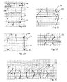
- Figure 2 shows a first possibility with the profile body 31 being a profiled metal wire.
- the profile body has a cross shaped cross section.
- the profile body 31 is initially embedded in the second object 2 so that the second undercut portion (in the depicted configuration formed by the lower half of the profile body) is immersed in the second object 2.
- the second object may be of any suitable material, including a thermoplastic or a thermosetting polymer, both with or without reinforcement, or also a metal.
- the material of the second object in which the profile body is embedded may but does not need to be liquefiable.
- the first object 1 is pressed against the second object while mechanical vibration energy is coupled into the first object and/or the second object. This is continued until in a region around the profile body 31 enough thermoplastic material of the first object 1 is made flowable for those parts of the profile body that are not within the second object to be immersed in the second object and the surfaces of the first and second objects lying against each other.
- Figure 3 shows the second possibility in which both, the first and second objects 1, 2 both comprise thermoplastic material and the profile body 31 is initially separate.
- Fig. 3 illustrates the mechanical vibration acting from the side of the first object 1 (sonotrode 6). However, it would also be possible to couple the vibration in from the second object side or from both sides.
- the application of the mechanical vibration causes materials of the first and second objects to flow around the profile body (metal wire) length to create a continuous positive-fit connection along a whole length of the profile body.
- a connection following a linear profile - defined by how the profile body is placed - may result.
- the connection may be watertight and replace a gluing connection.
- Figure 4 shows the resulting situation with the flow portion 12 re-solidified.
- the flow portion 12 is illustrated on both sides, i.e. in the first and in the second object, as is the case if the initial configuration is the one of Fig. 3 .
- the initial configuration is the one of Fig. 3 .
- the cross section of the profile body may be tuned to suit the different properties of these materials.
- the cross section and an edge profile thereof may be optimized for insertion with the help of the mechanical vibration to the specific melting characteristics of the materials.
- Figures 5-8 illustrate according alternative profiles.
- the profile shown in Figure 5 is may be especially suited if the first object 1 material is comparably hard and/or becomes flowable only at a somewhat more elevated temperature than the material of the second object.
- the one portion of the profile body (upper edge in Fig. 5 ) that faces the first object has a more cutting characteristic, whereas the portion that faces the second object is less cutting, in Fig. 5 by having two spaced-apart edges that are at an angle to the axial direction.
- Figs. 6-8 comprise barb-like structures that contribute to the undercut.
- Figure 9 depicts an embodiment in which in addition to connection by the profile body - which is shaped similarly to Fig. 3 - also a weld between the first and second objects is achieved.
- the first object surface portion 11 is provided with a plurality of energy directors, such as energy directing ridges running perpendicular to the drawing plane. After the flow portion has become flowable and the first and second object surface portions get into physical contact, the mechanical vibration energy and pressing force will cause thermoplastic material to become flowable also at the interface between the first and second objects and thereby cause a weld.
- Profile bodies 31 that are embedded in material of the two objects that are welded to each other also serve as reinforcement objects as described in somewhat more detail hereinafter.
- FIG 10 shows an embodiment in which the profile body 31 has the following further features:
- the embodiments of the disclosure involve coupling the mechanical vibration energy and the relative pressing force into the first object or the second object only (or, in special embodiments, also into the first object and the second object) but not directly into the profile body.
- the movement of the profile body relative to the first/second objects nor its position can be directly controlled, at least not in situations where initially the profile body is separate from both, the first and second objects (as in Fig. 3 ), i.e. is not firmly connected to any one of these.
- the profile body may be caused to be embedded in the second or first object first and only when it has penetrated to the desired level in this second/first object then material of the other one of the objects may be caused to become flowable in sufficient amount for the profile body to penetrate therein, too.
- a stabilizer portion 35 of the kind shown in Fig. 10 may be used to define the penetration depth and the position and orientation of the profile body relative to the first/second objects.
- the stabilizer portion extends over a substantial area parallel to the plane defined by the surface portions and substantially inhibits for example even prevents a material flow across this area over which it extends.
- the stabilizer portion may be sheet-like.
- FIG. 11 shows an average diameter d f of the flow portions caused by the first anchoring portions 36 in relation to the extension d of the stabilizer portion.
- the axial (z-) position of the stabilizer portion with respect to the first and second objects as well as its orientation are exactly defined by the respective surface portions. This also defines the penetration depth of the anchoring portions 36, 37.
- the anchoring portion stabilizer portion 35 serves as stop for the first face and thereafter may assist the energy transfer through the assembly.
- the embodiment of Fig. 11 has optional barb features 38 causing the undercuts and being caused by folded outermost portions of the anchoring portions.
- the uncercut could be caused by the anchoring portions 36, 37 projecting into a direction that is not parallel to the axial direction, as for example shown in Figure 12 .
- thermoplastic material starts becoming flowable if both, the first and the second object comprise thermoplastic material at least at the surface portions in contact with the profile body 31:
- these parameters may be used to level the differences out to ensure that the profile body is embedded in the two objects to a similar extent.
- one of the other mentioned parameters material properties, energy directing properties, angle
- the other parameters may be used to compensate.
- the profile body has a stabilizer portion, an asymmetry of the liquefaction properties may be desired, and the parameters may be used to ensure a controlled liquefaction and embedding process.
- Figure 14 depicts a profile body 31 with a stabilizer portion 35 that laterally extends further than the locations from which the anchoring portions 36, 37 project.
- a profile body of this kind has a stabilizing effect also if the neighbouring anchoring portions are close together, and even if they project from a same location (which would for example be the case if the profile body of Figures 2, 3, and 9 was provided with an additional stabilizer portion extending between the first and second objects, for example essentially parallel to their respective surfaces).
- the lateral extension of the stabilizer portion is sufficient so that thermoplastic material portions of the respective first/second object that come into contact with the laterally extending portions (laterally of the anchoring portion) of the stabilizer portion remain solid.
- Figure 15 shows an embodiment in which the profile body 31 in contrast to the previously discussed embodiments does not only substantially extend in one in-plane dimension, like a wire, but has a substantial extension in two in-plane dimensions.
- the x-z-cross section remains constant along the y direction, i.e. the profile body has a symmetry along the y axis.
- Two-dimensional profile bodies may be used to achieve a two-dimensional bond.
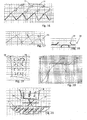
- Figure 16 shows an embodiment of a profile body 31 that is made of a folded metal sheet with a pattern of through holes 71 along the proximal and distal (upper and lower) edges.
- the portions around the holes 71 form the respective undercuts in that the material in contact with the respective edges when liquefied flows through the holes and into the space underneath the holes.
- This embodiment deals with the above-mentioned possible disadvantage in that it also locks the first and second objects to each other with respect to relative movements in y-direction.
- Figure 17 shows a section through a further embodiment of a profile body 31 (that extends into the y-direction perpendicular to the drawing plane). Given a sufficient lateral (x-direction) extension, the profile body 31 of the kind shown in Fig. 17 may completely separate the material of the first and second objects from each other, i.e. the first object material flows into the undercut structures on one side of the profile body, and the second object material flows in to the undercut structures on the other side only.
- the profile body 31 shown in section in Figure 18 and in top view in Figure 19 comprises a strip of a sheet material with a plurality of tongues 33 cut out of the sheet material and bent towards the proximal or distal side, respectively.
- the tongues and the direction towards which they are bent form a regular pattern.
- the profile body 31 could also be endless (i.e. capable of being cut in any shape) in both lateral dimensions.
- Figure 20 illustrates a process diagram.
- the figure shows the pressing force 91 and the vibration power 92 as a function of time.
- the pressing force 91 may be maintained for some time after the vibrations are switched off (post-pressing phase).
- the pressing force may even be raised (dashed line).
- Figure 21 yet illustrates the process of embedding the profile body 31 in thermoplastic material of the second object 2 for embodiments in which the first object 1 is positioned only after the profile body has been embedded in the second object, possibly after the flow portion of the second object thermoplastic material has re-solidified.
- the profile body 31 is illustrated to comprise a stabilizer portion 35 that during the step of embedding the profile body in the second object serves as a stop and that also during the subsequent step of embedding in the first object (compare Fig. 2 ) ensures that the first undercut is embedded in the first object, i.e. that the profile body is not driven further into the second object.
- the profile body comprising the stabilizer portion 35 also other measures could be taken to ensure this.
- the second object may be chosen to be the object that has the thermoplastic material with the higher liquefaction temperature.
- the measures discussed referring to Figures 12 and 13 and/or the placement of the sonotrode relative to the arrangement may be sued as such measure.
Landscapes
- Engineering & Computer Science (AREA)
- Mechanical Engineering (AREA)
- Physics & Mathematics (AREA)
- Thermal Sciences (AREA)
- Lining Or Joining Of Plastics Or The Like (AREA)
- Standing Axle, Rod, Or Tube Structures Coupled By Welding, Adhesion, Or Deposition (AREA)
- Casting Or Compression Moulding Of Plastics Or The Like (AREA)
- Food-Manufacturing Devices (AREA)
- Pressure Welding/Diffusion-Bonding (AREA)
Claims (12)
- Verfahren zum Verbinden eines ersten Objekts (1) mit einem zweiten Objekt (2), wobei das erste und das zweite Objekt jeweils einen Oberflächenabschnitt aufweisen, das Verfahren Folgendes umfassend:• Bereitstellen des ersten und des zweiten Objekts und weiterhin Bereitstellen eines Profilkörpers, der sich entlang einer Längsrichtung erstreckt und eine Gestalt aufweist, die einen ersten und einen zweiten Hinterschnitt definiert,• wobei das Verfahren gekennzeichnet ist durch Einbetten des Profilkörpers (31) in dem zweiten Objekt (2) entlang des zweiten Objektoberflächenabschnitts, so dass der zweite Hinterschnitt in einem Material des zweiten Objekts ist,• und Einbetten des Profilkörpers (31) in dem ersten Objekt (1) entlang des ersten Objektoberflächenabschnitts, so dass der erste Hinterschnitt in einem thermoplastischen Material des ersten Objekts ist,• wobei mindestens Einbetten des Profilkörpers (31) in dem ersten Objekt (1) durch mechanische Energie bewirkt wird, die auf dem ersten Objekt (1) und/oder auf dem zweiten Objekt (2) auftrifft, während das erste Objekt (1) und das zweite Objekt (2) gegeneinander gedrückt werden, und wobei mindestens eine der folgenden Bedingungen erfüllt ist:• Einbetten des Profilkörpers (31) in dem zweiten Objekt wird vor dem Einbetten des Profilkörpers in dem ersten Objekt ausgeführt, so dass, während des Schritts des Einbettens des Profilkörpers in dem ersten Objekt, der Profilkörper in dem zweiten Objekt eingebettet wird;• der Profilkörper umfasst einen Stabilisierungsmittelabschnitt (35) und mindestens einen ersten Verankerungsabschnitt (36), der den ersten Hinterschnitt ausbildet, der in einer ersten Richtung aus dem Stabilisierungsmittelabschnitt (35) vorsteht, und mindestens einen zweiten Verankerungsabschnitt (37), der den zweiten Hinterschnitt ausbildet, der in einer zweiten Richtung aus dem Stabilisierungsmittelabschnitt (35) vorsteht, wobei der Schritt des Einbettens des Profilkörpers in dem ersten Objekt und/oder in dem zweiten Objekt Bewirken umfasst, dass sich der Stabilisierungsmittelabschnitt zwischen dem ersten und dem zweiten Objektoberflächenabschnitt erstreckt.
- Verfahren nach Anspruch 1, wobei der Schritt des Einbettens des Profilkörpers (31) in dem ersten Objekt ausgeführt wird, bis der erste Objektoberflächenabschnitt und der zweite Objektoberflächenabschnitt gegeneinander liegen.
- Verfahren nach Anspruch 1 oder 2, wobei das zweite Objekt (2) entlang des zweiten Objektoberflächenabschnitts thermoplastisches Material aufweist und wobei Einbetten des Profilkörpers (31) in dem zweiten Objekt entlang des zweiten Objektoberflächenabschnitts Einbetten des Profilkörpers (31) in diesem thermoplastischen Material des zweiten Objekts umfasst.
- Verfahren nach Anspruch 3, wobei der Schritt des Einbettens des Profilkörpers (31) in dem zweiten Objekt (2) gleichzeitig mit dem Schritt des Einbettens des Profilkörpers in dem ersten Objekt (1) ausgeführt wird und durch die mechanische Energie bewirkt wird.
- Verfahren nach Anspruch 3 oder 4, wobei der Profilkörper (31), um in dem ersten und dem zweiten Objekt (1, 2) eingebettet zu werden, in Bezug auf das erste und das zweite Objekt zwischen den Oberflächenabschnitten des ersten und des zweiten Objekts angeordnet ist und wobei der Schritt des Einbettens des Profilkörpers in dem ersten Objekt und der Schritt des Einbettens des Profilkörpers in dem zweiten Objekt Koppeln einer Andruckkraft und mechanischer Schwingungsenergie in mindestens einem des ersten und des zweiten Objekts umfassen, wobei die Andruckkraft bewirkt, dass der Profilkörper zwischen dem ersten und dem zweiten Objekt geklemmt wird.
- Verfahren nach einem der vorhergehenden Ansprüche, wobei Bewirken, dass mechanische Energie auf das erste Objekt (1) und/oder auf das zweite Objekt (2) auftrifft, und Bewirken, dass das erste und das zweite Objekt gegeneinander gedrückt werden, Verwenden einer schwingenden Sonotrode (6) umfassen, um das erste und das zweite Objekt gegeneinander zu drücken.
- Verfahren nach einem der vorhergehenden Ansprüche, wobei der Stabilisierungsmittelabschnitt (35) im Wesentlichen eben ist und wobei der Schritt des Drückens und des Bewirkens, dass Energie auftrifft, ausgeführt wird, bis sowohl der erste Oberflächenabschnitt als auch der zweite Oberflächenabschnitt gegen den Stabilisierungsmittelabschnitt anliegen.
- Verfahren nach einem der vorhergehenden Ansprüche, wobei der Profilkörper (31) mindestens zwei erste Verankerungsabschnitte (36) und/oder mindestens zwei zweite Verankerungsabschnitte (37) umfasst und wobei beispielsweise in dem Schritt des Einbettens des Profilkörpers in dem ersten Objekt und/oder in dem zweiten Objekt ein Materialabschnitt des ersten Objekts (1) bzw. des zweiten Objekts (2) zwischen zwei benachbarten Verankerungsabschnitten fest bleibt.
- Verfahren nach einem der vorhergehenden Ansprüche, wobei das zweite Objekt (2) entlang des zweiten Objektoberflächenabschnitts thermoplastisches Material aufweist und wobei die Schritte des Einbettens des ersten Verankerungsabschnitts (36) in dem ersten Objekt (1) und des Einbettens des zweiten Verankerungsabschnitts (37) in dem zweiten Objekt sequenziell, einer nach dem anderen, ausgeführt werden.
- Verfahren nach einem der vorhergehenden Ansprüche und Bewirken einer Schweißung zwischen thermoplastischen Abschnitten des ersten und des zweiten Objekts (1, 2) an den Oberflächenabschnitten umfassend, wobei die Schweißung beispielsweise durch die mechanische Energie bewirkt wird.
- Verfahren nach einem der vorhergehenden Ansprüche, wobei der Profilkörper (31) ein profilierter Draht oder ein profilierter Stab ist.
- Verfahren nach einem der Ansprüche 1 bis 10, wobei der Profilkörper (31) ein zweidimensionales Objekt ist, das sich entlang von zwei Dimensionen in einer Ebene erstreckt, wobei der Profilkörper beispielsweise ein gefaltetes Metallblech mit mehreren durchgehenden Öffnungen (71) umfasst.
Priority Applications (1)
| Application Number | Priority Date | Filing Date | Title |
|---|---|---|---|
| PL16738092T PL3319783T3 (pl) | 2015-07-06 | 2016-07-05 | Zespajanie ze sobą przedmiotów |
Applications Claiming Priority (2)
| Application Number | Priority Date | Filing Date | Title |
|---|---|---|---|
| CH9822015 | 2015-07-06 | ||
| PCT/EP2016/065780 WO2017005721A1 (en) | 2015-07-06 | 2016-07-05 | Bonding objects together |
Publications (2)
| Publication Number | Publication Date |
|---|---|
| EP3319783A1 EP3319783A1 (de) | 2018-05-16 |
| EP3319783B1 true EP3319783B1 (de) | 2021-02-24 |
Family
ID=53546091
Family Applications (3)
| Application Number | Title | Priority Date | Filing Date |
|---|---|---|---|
| EP16736069.2A Active EP3319782B1 (de) | 2015-07-06 | 2016-07-05 | Verbinden von komponenten |
| EP20207213.8A Active EP3795338B1 (de) | 2015-07-06 | 2016-07-05 | Verbindung von objekten |
| EP16738092.2A Active EP3319783B1 (de) | 2015-07-06 | 2016-07-05 | Verbinden von objekten |
Family Applications Before (2)
| Application Number | Title | Priority Date | Filing Date |
|---|---|---|---|
| EP16736069.2A Active EP3319782B1 (de) | 2015-07-06 | 2016-07-05 | Verbinden von komponenten |
| EP20207213.8A Active EP3795338B1 (de) | 2015-07-06 | 2016-07-05 | Verbindung von objekten |
Country Status (13)
| Country | Link |
|---|---|
| US (2) | US10807313B2 (de) |
| EP (3) | EP3319782B1 (de) |
| JP (1) | JP6871904B2 (de) |
| KR (1) | KR102550934B1 (de) |
| CN (1) | CN107735242B (de) |
| AU (1) | AU2016289742B2 (de) |
| BR (1) | BR112017023782B1 (de) |
| ES (1) | ES2867774T3 (de) |
| MX (1) | MX2017015356A (de) |
| PL (1) | PL3319783T3 (de) |
| RU (1) | RU2731394C2 (de) |
| WO (2) | WO2017005721A1 (de) |
| ZA (1) | ZA201707295B (de) |
Families Citing this family (5)
| Publication number | Priority date | Publication date | Assignee | Title |
|---|---|---|---|---|
| US10464282B2 (en) * | 2016-01-21 | 2019-11-05 | GM Global Technology Operations LLC | Systems and processes for joining workpieces robustly using moguls and adhesive |
| MX2019011140A (es) * | 2017-03-20 | 2020-02-05 | Multimaterial Welding Ag | Union de objetos entre ellos. |
| DE102017211470A1 (de) | 2017-07-05 | 2019-01-10 | Bayerische Motoren Werke Aktiengesellschaft | Halteanordnung eines Beplankungsteils an einem Tragelement eines Kraftfahrzeugs, Haltevorrichtung für eine Halteanordnung und Verfahren zum Anordnen eines Beplankungsteils an einem Tragelement eines Kraftfahrzeugs |
| US10960611B2 (en) * | 2017-09-06 | 2021-03-30 | Divergent Technologies, Inc. | Methods and apparatuses for universal interface between parts in transport structures |
| JP6964502B2 (ja) * | 2017-12-07 | 2021-11-10 | 三菱重工業株式会社 | 複合材料の接合方法 |
Family Cites Families (22)
| Publication number | Priority date | Publication date | Assignee | Title |
|---|---|---|---|---|
| CH77816A (fr) | 1916-11-15 | 1918-06-01 | Aera Soc | Indicateur de vitesse |
| FR1519111A (fr) * | 1966-04-14 | 1968-03-29 | Cavitron Ultrasonics | Dispositif de fixation destinés à être introduits dans un élément de réception |
| NL7206781A (de) * | 1972-01-10 | 1973-07-12 | ||
| FR2291843A1 (fr) * | 1974-11-25 | 1976-06-18 | Peugeot & Renault | Fixation d'enjoliveurs sur pieces plastiques |
| US4058421A (en) | 1976-10-07 | 1977-11-15 | Branson Ultrasonics Corporation | Method of joining non-fusible workpieces using frictional energy |
| DE2744553C2 (de) * | 1977-10-04 | 1982-12-09 | W. Hartmann & Co (Gmbh & Co), 2000 Hamburg | Verbundprofilstab |
| US4358328A (en) * | 1979-04-17 | 1982-11-09 | Minnesota Mining And Manufacturing Company | Tape-cutting blade attaching method |
| DE3861531D1 (de) * | 1987-03-23 | 1991-02-21 | Ebauchesfabrik Eta Ag | Uhrengehaeuse, einheit zu dessen herstellung und verfahren zum bauen dieser einheit. |
| DE3724253A1 (de) * | 1987-07-22 | 1989-02-02 | Hartmann & Co W | Waermedaemmendes verbundprofil |
| DE3835640A1 (de) * | 1988-10-19 | 1990-04-26 | Bayerische Motoren Werke Ag | Verfahren zum formschluessigen verbinden zweier formteile |
| US6514593B1 (en) * | 1999-08-23 | 2003-02-04 | Northrop Grumman Corporation | Mechanically locking Z-pins |
| DE10210075B4 (de) * | 2002-03-08 | 2008-04-30 | Stapla Ultraschall-Technik Gmbh | Vorrichtung zum Abdichten und Trennen eines Rohrabschnitts |
| EP1614525A1 (de) * | 2004-07-07 | 2006-01-11 | Woodwelding AG | Verfahren zum Verbinden von zwei Teilen und entsprechendes Verbindungsteil |
| GB0704753D0 (en) * | 2007-03-13 | 2007-04-18 | Airbus Uk Ltd | Preparation of a component for use in a joint |
| US8518314B2 (en) | 2007-10-25 | 2013-08-27 | Woodwelding Ag | Method of fixation for a mechanical dowel |
| DE102008017822A1 (de) * | 2008-04-08 | 2009-10-15 | Continental Automotive Gmbh | Verfahren zum Herstellen eines hydraulischen Anschlusses für ein Fluidelement und Hydraulischer Anschluss für ein Fluidelement |
| DE102009044210A1 (de) * | 2009-10-08 | 2011-04-28 | Hettich-Heinze Gmbh & Co. Kg | Dübel und Verfahren zur Montage eines Dübels in eine Leichtbauplatte |
| CN102343673B (zh) * | 2010-07-23 | 2014-12-31 | 晟铭电子科技股份有限公司 | 金属板上设置轻量化接架的制程 |
| EP2447790A1 (de) * | 2010-10-27 | 2012-05-02 | The Swatch Group Research and Development Ltd. | Glas für die obere Abdeckung des Gehäuses eines tragbaren Gegenstands |
| DE102011086791B4 (de) * | 2011-11-22 | 2024-08-22 | Vitesco Technologies GmbH | Verfahren zum Verschließen einer Bohrung eines Werkstückes und Bohrungsverschlussvorrichtung |
| DE102012203878B3 (de) * | 2012-03-13 | 2013-04-04 | Bayerische Motoren Werke Aktiengesellschaft | Bauteilverbindung |
| KR102342932B1 (ko) | 2014-02-04 | 2021-12-24 | 부트벨딩 에스아 | 커넥터 및 이를 이용하는 방법 |
-
2016
- 2016-07-05 EP EP16736069.2A patent/EP3319782B1/de active Active
- 2016-07-05 ES ES16738092T patent/ES2867774T3/es active Active
- 2016-07-05 US US15/578,784 patent/US10807313B2/en active Active
- 2016-07-05 BR BR112017023782-2A patent/BR112017023782B1/pt not_active IP Right Cessation
- 2016-07-05 MX MX2017015356A patent/MX2017015356A/es unknown
- 2016-07-05 WO PCT/EP2016/065780 patent/WO2017005721A1/en not_active Ceased
- 2016-07-05 EP EP20207213.8A patent/EP3795338B1/de active Active
- 2016-07-05 PL PL16738092T patent/PL3319783T3/pl unknown
- 2016-07-05 RU RU2018102757A patent/RU2731394C2/ru active
- 2016-07-05 KR KR1020187001321A patent/KR102550934B1/ko active Active
- 2016-07-05 EP EP16738092.2A patent/EP3319783B1/de active Active
- 2016-07-05 US US15/564,601 patent/US20180071993A1/en not_active Abandoned
- 2016-07-05 AU AU2016289742A patent/AU2016289742B2/en not_active Ceased
- 2016-07-05 CN CN201680034470.7A patent/CN107735242B/zh active Active
- 2016-07-05 JP JP2018500439A patent/JP6871904B2/ja not_active Expired - Fee Related
- 2016-07-05 WO PCT/EP2016/065779 patent/WO2017005720A1/en not_active Ceased
-
2017
- 2017-10-26 ZA ZA2017/07295A patent/ZA201707295B/en unknown
Non-Patent Citations (1)
| Title |
|---|
| ANONYMOUS: "Profils extrudés en aluminium par filage - My Little Blog Fonderie", 26 February 2014 (2014-02-26), pages 1 - 14, XP055641174, Retrieved from the Internet <URL:http://souspression.canalblog.com/archives/2011/02/14/19995093.html> [retrieved on 20191111] * |
Also Published As
| Publication number | Publication date |
|---|---|
| CN107735242B (zh) | 2020-04-14 |
| AU2016289742A1 (en) | 2017-11-23 |
| JP2018520916A (ja) | 2018-08-02 |
| US10807313B2 (en) | 2020-10-20 |
| BR112017023782B1 (pt) | 2022-05-03 |
| KR102550934B1 (ko) | 2023-07-03 |
| JP6871904B2 (ja) | 2021-05-19 |
| EP3795338A1 (de) | 2021-03-24 |
| RU2731394C2 (ru) | 2020-09-02 |
| WO2017005720A1 (en) | 2017-01-12 |
| EP3319783A1 (de) | 2018-05-16 |
| WO2017005721A1 (en) | 2017-01-12 |
| PL3319783T3 (pl) | 2021-08-23 |
| EP3795338B1 (de) | 2023-05-17 |
| US20180111325A1 (en) | 2018-04-26 |
| ZA201707295B (en) | 2019-01-30 |
| KR20180026456A (ko) | 2018-03-12 |
| US20180071993A1 (en) | 2018-03-15 |
| CN107735242A (zh) | 2018-02-23 |
| EP3319782B1 (de) | 2020-12-02 |
| MX2017015356A (es) | 2018-03-28 |
| RU2018102757A (ru) | 2019-08-06 |
| EP3319782A1 (de) | 2018-05-16 |
| ES2867774T3 (es) | 2021-10-20 |
| AU2016289742B2 (en) | 2021-11-25 |
| BR112017023782A2 (pt) | 2018-07-17 |
| RU2018102757A3 (de) | 2019-10-28 |
Similar Documents
| Publication | Publication Date | Title |
|---|---|---|
| US10807313B2 (en) | Bonding objects together | |
| KR102455170B1 (ko) | 제2 물체를 제1 물체에 고정 | |
| EP3307520B1 (de) | Verankerung in einem leichtbauelement | |
| EP3307521B1 (de) | Befestigung eines zweiten objekts an einem ersten objekt | |
| WO2015117253A1 (en) | Connector and method of using the same | |
| EP3487686B1 (de) | Befestigung eines zweiten objekts an einem ersten objekt | |
| JP2020511339A (ja) | 物体の接合方法 | |
| US10337543B2 (en) | Securing a second object to a first object | |
| EP3606729B1 (de) | Verbindung von objekten | |
| EP3385551B1 (de) | Adapter zum befestigen von objekten aneinander | |
| US20230058504A1 (en) | Securing a second object to a first object |
Legal Events
| Date | Code | Title | Description |
|---|---|---|---|
| STAA | Information on the status of an ep patent application or granted ep patent |
Free format text: STATUS: THE INTERNATIONAL PUBLICATION HAS BEEN MADE |
|
| PUAI | Public reference made under article 153(3) epc to a published international application that has entered the european phase |
Free format text: ORIGINAL CODE: 0009012 |
|
| STAA | Information on the status of an ep patent application or granted ep patent |
Free format text: STATUS: REQUEST FOR EXAMINATION WAS MADE |
|
| 17P | Request for examination filed |
Effective date: 20171122 |
|
| AK | Designated contracting states |
Kind code of ref document: A1 Designated state(s): AL AT BE BG CH CY CZ DE DK EE ES FI FR GB GR HR HU IE IS IT LI LT LU LV MC MK MT NL NO PL PT RO RS SE SI SK SM TR |
|
| AX | Request for extension of the european patent |
Extension state: BA ME |
|
| DAV | Request for validation of the european patent (deleted) | ||
| DAX | Request for extension of the european patent (deleted) | ||
| RIN1 | Information on inventor provided before grant (corrected) |
Inventor name: KVIST, JOAKIM Inventor name: AESCHLIMANN, MARCEL Inventor name: LEHMANN, MARIO Inventor name: MAYER, JOERG Inventor name: POSCHNER, PATRICIA |
|
| STAA | Information on the status of an ep patent application or granted ep patent |
Free format text: STATUS: EXAMINATION IS IN PROGRESS |
|
| 17Q | First examination report despatched |
Effective date: 20191118 |
|
| REG | Reference to a national code |
Ref country code: DE Ref legal event code: R079 Ref document number: 602016053090 Country of ref document: DE Free format text: PREVIOUS MAIN CLASS: B29C0065080000 Ipc: B29C0065560000 |
|
| GRAP | Despatch of communication of intention to grant a patent |
Free format text: ORIGINAL CODE: EPIDOSNIGR1 |
|
| STAA | Information on the status of an ep patent application or granted ep patent |
Free format text: STATUS: GRANT OF PATENT IS INTENDED |
|
| RIC1 | Information provided on ipc code assigned before grant |
Ipc: B29C 65/56 20060101AFI20200826BHEP Ipc: B29C 65/64 20060101ALI20200826BHEP Ipc: B29C 65/08 20060101ALN20200826BHEP |
|
| RIC1 | Information provided on ipc code assigned before grant |
Ipc: B29C 65/64 20060101ALI20200903BHEP Ipc: B29C 65/56 20060101AFI20200903BHEP Ipc: B29C 65/08 20060101ALN20200903BHEP |
|
| INTG | Intention to grant announced |
Effective date: 20200918 |
|
| GRAS | Grant fee paid |
Free format text: ORIGINAL CODE: EPIDOSNIGR3 |
|
| GRAA | (expected) grant |
Free format text: ORIGINAL CODE: 0009210 |
|
| STAA | Information on the status of an ep patent application or granted ep patent |
Free format text: STATUS: THE PATENT HAS BEEN GRANTED |
|
| AK | Designated contracting states |
Kind code of ref document: B1 Designated state(s): AL AT BE BG CH CY CZ DE DK EE ES FI FR GB GR HR HU IE IS IT LI LT LU LV MC MK MT NL NO PL PT RO RS SE SI SK SM TR |
|
| REG | Reference to a national code |
Ref country code: CH Ref legal event code: EP |
|
| REG | Reference to a national code |
Ref country code: DE Ref legal event code: R096 Ref document number: 602016053090 Country of ref document: DE |
|
| REG | Reference to a national code |
Ref country code: AT Ref legal event code: REF Ref document number: 1363910 Country of ref document: AT Kind code of ref document: T Effective date: 20210315 |
|
| REG | Reference to a national code |
Ref country code: IE Ref legal event code: FG4D |
|
| REG | Reference to a national code |
Ref country code: SE Ref legal event code: TRGR |
|
| REG | Reference to a national code |
Ref country code: CH Ref legal event code: NV Representative=s name: FREI PATENTANWALTSBUERO AG, CH |
|
| REG | Reference to a national code |
Ref country code: LT Ref legal event code: MG9D |
|
| REG | Reference to a national code |
Ref country code: NL Ref legal event code: MP Effective date: 20210224 |
|
| PG25 | Lapsed in a contracting state [announced via postgrant information from national office to epo] |
Ref country code: NO Free format text: LAPSE BECAUSE OF FAILURE TO SUBMIT A TRANSLATION OF THE DESCRIPTION OR TO PAY THE FEE WITHIN THE PRESCRIBED TIME-LIMIT Effective date: 20210524 Ref country code: PT Free format text: LAPSE BECAUSE OF FAILURE TO SUBMIT A TRANSLATION OF THE DESCRIPTION OR TO PAY THE FEE WITHIN THE PRESCRIBED TIME-LIMIT Effective date: 20210624 Ref country code: FI Free format text: LAPSE BECAUSE OF FAILURE TO SUBMIT A TRANSLATION OF THE DESCRIPTION OR TO PAY THE FEE WITHIN THE PRESCRIBED TIME-LIMIT Effective date: 20210224 Ref country code: GR Free format text: LAPSE BECAUSE OF FAILURE TO SUBMIT A TRANSLATION OF THE DESCRIPTION OR TO PAY THE FEE WITHIN THE PRESCRIBED TIME-LIMIT Effective date: 20210525 Ref country code: HR Free format text: LAPSE BECAUSE OF FAILURE TO SUBMIT A TRANSLATION OF THE DESCRIPTION OR TO PAY THE FEE WITHIN THE PRESCRIBED TIME-LIMIT Effective date: 20210224 Ref country code: LT Free format text: LAPSE BECAUSE OF FAILURE TO SUBMIT A TRANSLATION OF THE DESCRIPTION OR TO PAY THE FEE WITHIN THE PRESCRIBED TIME-LIMIT Effective date: 20210224 Ref country code: BG Free format text: LAPSE BECAUSE OF FAILURE TO SUBMIT A TRANSLATION OF THE DESCRIPTION OR TO PAY THE FEE WITHIN THE PRESCRIBED TIME-LIMIT Effective date: 20210524 |
|
| PG25 | Lapsed in a contracting state [announced via postgrant information from national office to epo] |
Ref country code: RS Free format text: LAPSE BECAUSE OF FAILURE TO SUBMIT A TRANSLATION OF THE DESCRIPTION OR TO PAY THE FEE WITHIN THE PRESCRIBED TIME-LIMIT Effective date: 20210224 Ref country code: LV Free format text: LAPSE BECAUSE OF FAILURE TO SUBMIT A TRANSLATION OF THE DESCRIPTION OR TO PAY THE FEE WITHIN THE PRESCRIBED TIME-LIMIT Effective date: 20210224 Ref country code: NL Free format text: LAPSE BECAUSE OF FAILURE TO SUBMIT A TRANSLATION OF THE DESCRIPTION OR TO PAY THE FEE WITHIN THE PRESCRIBED TIME-LIMIT Effective date: 20210224 |
|
| PG25 | Lapsed in a contracting state [announced via postgrant information from national office to epo] |
Ref country code: IS Free format text: LAPSE BECAUSE OF FAILURE TO SUBMIT A TRANSLATION OF THE DESCRIPTION OR TO PAY THE FEE WITHIN THE PRESCRIBED TIME-LIMIT Effective date: 20210624 |
|
| REG | Reference to a national code |
Ref country code: ES Ref legal event code: FG2A Ref document number: 2867774 Country of ref document: ES Kind code of ref document: T3 Effective date: 20211020 |
|
| PG25 | Lapsed in a contracting state [announced via postgrant information from national office to epo] |
Ref country code: SM Free format text: LAPSE BECAUSE OF FAILURE TO SUBMIT A TRANSLATION OF THE DESCRIPTION OR TO PAY THE FEE WITHIN THE PRESCRIBED TIME-LIMIT Effective date: 20210224 Ref country code: EE Free format text: LAPSE BECAUSE OF FAILURE TO SUBMIT A TRANSLATION OF THE DESCRIPTION OR TO PAY THE FEE WITHIN THE PRESCRIBED TIME-LIMIT Effective date: 20210224 |
|
| REG | Reference to a national code |
Ref country code: DE Ref legal event code: R097 Ref document number: 602016053090 Country of ref document: DE |
|
| PG25 | Lapsed in a contracting state [announced via postgrant information from national office to epo] |
Ref country code: DK Free format text: LAPSE BECAUSE OF FAILURE TO SUBMIT A TRANSLATION OF THE DESCRIPTION OR TO PAY THE FEE WITHIN THE PRESCRIBED TIME-LIMIT Effective date: 20210224 Ref country code: SK Free format text: LAPSE BECAUSE OF FAILURE TO SUBMIT A TRANSLATION OF THE DESCRIPTION OR TO PAY THE FEE WITHIN THE PRESCRIBED TIME-LIMIT Effective date: 20210224 Ref country code: RO Free format text: LAPSE BECAUSE OF FAILURE TO SUBMIT A TRANSLATION OF THE DESCRIPTION OR TO PAY THE FEE WITHIN THE PRESCRIBED TIME-LIMIT Effective date: 20210224 |
|
| PLBE | No opposition filed within time limit |
Free format text: ORIGINAL CODE: 0009261 |
|
| STAA | Information on the status of an ep patent application or granted ep patent |
Free format text: STATUS: NO OPPOSITION FILED WITHIN TIME LIMIT |
|
| PG25 | Lapsed in a contracting state [announced via postgrant information from national office to epo] |
Ref country code: AL Free format text: LAPSE BECAUSE OF FAILURE TO SUBMIT A TRANSLATION OF THE DESCRIPTION OR TO PAY THE FEE WITHIN THE PRESCRIBED TIME-LIMIT Effective date: 20210224 |
|
| 26N | No opposition filed |
Effective date: 20211125 |
|
| PG25 | Lapsed in a contracting state [announced via postgrant information from national office to epo] |
Ref country code: SI Free format text: LAPSE BECAUSE OF FAILURE TO SUBMIT A TRANSLATION OF THE DESCRIPTION OR TO PAY THE FEE WITHIN THE PRESCRIBED TIME-LIMIT Effective date: 20210224 |
|
| PG25 | Lapsed in a contracting state [announced via postgrant information from national office to epo] |
Ref country code: MC Free format text: LAPSE BECAUSE OF FAILURE TO SUBMIT A TRANSLATION OF THE DESCRIPTION OR TO PAY THE FEE WITHIN THE PRESCRIBED TIME-LIMIT Effective date: 20210224 |
|
| REG | Reference to a national code |
Ref country code: BE Ref legal event code: MM Effective date: 20210731 |
|
| PG25 | Lapsed in a contracting state [announced via postgrant information from national office to epo] |
Ref country code: IS Free format text: LAPSE BECAUSE OF FAILURE TO SUBMIT A TRANSLATION OF THE DESCRIPTION OR TO PAY THE FEE WITHIN THE PRESCRIBED TIME-LIMIT Effective date: 20210624 Ref country code: LU Free format text: LAPSE BECAUSE OF NON-PAYMENT OF DUE FEES Effective date: 20210705 |
|
| PG25 | Lapsed in a contracting state [announced via postgrant information from national office to epo] |
Ref country code: IE Free format text: LAPSE BECAUSE OF NON-PAYMENT OF DUE FEES Effective date: 20210705 Ref country code: BE Free format text: LAPSE BECAUSE OF NON-PAYMENT OF DUE FEES Effective date: 20210731 |
|
| REG | Reference to a national code |
Ref country code: AT Ref legal event code: UEP Ref document number: 1363910 Country of ref document: AT Kind code of ref document: T Effective date: 20210224 |
|
| PG25 | Lapsed in a contracting state [announced via postgrant information from national office to epo] |
Ref country code: HU Free format text: LAPSE BECAUSE OF FAILURE TO SUBMIT A TRANSLATION OF THE DESCRIPTION OR TO PAY THE FEE WITHIN THE PRESCRIBED TIME-LIMIT; INVALID AB INITIO Effective date: 20160705 |
|
| PG25 | Lapsed in a contracting state [announced via postgrant information from national office to epo] |
Ref country code: CY Free format text: LAPSE BECAUSE OF FAILURE TO SUBMIT A TRANSLATION OF THE DESCRIPTION OR TO PAY THE FEE WITHIN THE PRESCRIBED TIME-LIMIT Effective date: 20210224 |
|
| P01 | Opt-out of the competence of the unified patent court (upc) registered |
Effective date: 20230616 |
|
| PG25 | Lapsed in a contracting state [announced via postgrant information from national office to epo] |
Ref country code: MK Free format text: LAPSE BECAUSE OF FAILURE TO SUBMIT A TRANSLATION OF THE DESCRIPTION OR TO PAY THE FEE WITHIN THE PRESCRIBED TIME-LIMIT Effective date: 20210224 |
|
| PG25 | Lapsed in a contracting state [announced via postgrant information from national office to epo] |
Ref country code: TR Free format text: LAPSE BECAUSE OF FAILURE TO SUBMIT A TRANSLATION OF THE DESCRIPTION OR TO PAY THE FEE WITHIN THE PRESCRIBED TIME-LIMIT Effective date: 20210224 |
|
| PGFP | Annual fee paid to national office [announced via postgrant information from national office to epo] |
Ref country code: CZ Payment date: 20240627 Year of fee payment: 9 |
|
| PG25 | Lapsed in a contracting state [announced via postgrant information from national office to epo] |
Ref country code: MT Free format text: LAPSE BECAUSE OF FAILURE TO SUBMIT A TRANSLATION OF THE DESCRIPTION OR TO PAY THE FEE WITHIN THE PRESCRIBED TIME-LIMIT Effective date: 20210224 |
|
| PGFP | Annual fee paid to national office [announced via postgrant information from national office to epo] |
Ref country code: GB Payment date: 20240725 Year of fee payment: 9 |
|
| PGFP | Annual fee paid to national office [announced via postgrant information from national office to epo] |
Ref country code: CH Payment date: 20240801 Year of fee payment: 9 Ref country code: ES Payment date: 20240828 Year of fee payment: 9 |
|
| PGFP | Annual fee paid to national office [announced via postgrant information from national office to epo] |
Ref country code: AT Payment date: 20240722 Year of fee payment: 9 |
|
| PGFP | Annual fee paid to national office [announced via postgrant information from national office to epo] |
Ref country code: PL Payment date: 20240701 Year of fee payment: 9 |
|
| PGFP | Annual fee paid to national office [announced via postgrant information from national office to epo] |
Ref country code: SE Payment date: 20240719 Year of fee payment: 9 |
|
| PGFP | Annual fee paid to national office [announced via postgrant information from national office to epo] |
Ref country code: DE Payment date: 20250722 Year of fee payment: 10 |
|
| PGFP | Annual fee paid to national office [announced via postgrant information from national office to epo] |
Ref country code: IT Payment date: 20250724 Year of fee payment: 10 |
|
| PGFP | Annual fee paid to national office [announced via postgrant information from national office to epo] |
Ref country code: FR Payment date: 20250725 Year of fee payment: 10 |
|
| PG25 | Lapsed in a contracting state [announced via postgrant information from national office to epo] |
Ref country code: CZ Free format text: LAPSE BECAUSE OF NON-PAYMENT OF DUE FEES Effective date: 20250705 |
|
| REG | Reference to a national code |
Ref country code: CH Ref legal event code: H13 Free format text: ST27 STATUS EVENT CODE: U-0-0-H10-H13 (AS PROVIDED BY THE NATIONAL OFFICE) Effective date: 20260224 |
|
| REG | Reference to a national code |
Ref country code: AT Ref legal event code: MM01 Ref document number: 1363910 Country of ref document: AT Kind code of ref document: T Effective date: 20250705 |
|
| GBPC | Gb: european patent ceased through non-payment of renewal fee |
Effective date: 20250705 |
|
| PG25 | Lapsed in a contracting state [announced via postgrant information from national office to epo] |
Ref country code: GB Free format text: LAPSE BECAUSE OF NON-PAYMENT OF DUE FEES Effective date: 20250705 |
|
| PG25 | Lapsed in a contracting state [announced via postgrant information from national office to epo] |
Ref country code: AT Free format text: LAPSE BECAUSE OF NON-PAYMENT OF DUE FEES Effective date: 20250705 |
|
| PG25 | Lapsed in a contracting state [announced via postgrant information from national office to epo] |
Ref country code: CH Free format text: LAPSE BECAUSE OF NON-PAYMENT OF DUE FEES Effective date: 20250731 |
|
| PG25 | Lapsed in a contracting state [announced via postgrant information from national office to epo] |
Ref country code: SE Free format text: LAPSE BECAUSE OF NON-PAYMENT OF DUE FEES Effective date: 20250706 |