EP3319902B1 - Robinet avec valve de distribution de liquide et membre perforateur pour poche - Google Patents
Robinet avec valve de distribution de liquide et membre perforateur pour poche Download PDFInfo
- Publication number
- EP3319902B1 EP3319902B1 EP16741451.5A EP16741451A EP3319902B1 EP 3319902 B1 EP3319902 B1 EP 3319902B1 EP 16741451 A EP16741451 A EP 16741451A EP 3319902 B1 EP3319902 B1 EP 3319902B1
- Authority
- EP
- European Patent Office
- Prior art keywords
- bag
- fitment
- piercing member
- piercing
- wall
- Prior art date
- Legal status (The legal status is an assumption and is not a legal conclusion. Google has not performed a legal analysis and makes no representation as to the accuracy of the status listed.)
- Active
Links
Images






Classifications
-
- B—PERFORMING OPERATIONS; TRANSPORTING
- B65—CONVEYING; PACKING; STORING; HANDLING THIN OR FILAMENTARY MATERIAL
- B65D—CONTAINERS FOR STORAGE OR TRANSPORT OF ARTICLES OR MATERIALS, e.g. BAGS, BARRELS, BOTTLES, BOXES, CANS, CARTONS, CRATES, DRUMS, JARS, TANKS, HOPPERS, FORWARDING CONTAINERS; ACCESSORIES, CLOSURES, OR FITTINGS THEREFOR; PACKAGING ELEMENTS; PACKAGES
- B65D77/00—Packages formed by enclosing articles or materials in preformed containers, e.g. boxes, cartons, sacks or bags
- B65D77/04—Articles or materials enclosed in two or more containers disposed one within another
- B65D77/06—Liquids or semi-liquids or other materials or articles enclosed in flexible containers disposed within rigid containers
- B65D77/062—Flexible containers disposed within polygonal containers formed by folding a carton blank
- B65D77/065—Spouts, pouring necks or discharging tubes fixed to or integral with the flexible container
- B65D77/067—Spouts, pouring necks or discharging tubes fixed to or integral with the flexible container combined with a valve, a tap or a piercer
-
- B—PERFORMING OPERATIONS; TRANSPORTING
- B67—OPENING, CLOSING OR CLEANING BOTTLES, JARS OR SIMILAR CONTAINERS; LIQUID HANDLING
- B67B—APPLYING CLOSURE MEMBERS TO BOTTLES JARS, OR SIMILAR CONTAINERS; OPENING CLOSED CONTAINERS
- B67B7/00—Hand- or power-operated devices for opening closed containers
- B67B7/24—Hole-piercing devices
- B67B7/26—Hole-piercing devices combined with spouts
-
- B—PERFORMING OPERATIONS; TRANSPORTING
- B67—OPENING, CLOSING OR CLEANING BOTTLES, JARS OR SIMILAR CONTAINERS; LIQUID HANDLING
- B67D—DISPENSING, DELIVERING OR TRANSFERRING LIQUIDS, NOT OTHERWISE PROVIDED FOR
- B67D3/00—Apparatus or devices for controlling flow of liquids under gravity from storage containers for dispensing purposes
- B67D3/0058—Details
- B67D3/0061—Details of liquid containers, e.g. filling, emptying, closing or opening means
- B67D3/0067—Details of liquid containers, e.g. filling, emptying, closing or opening means relating to shape or materials, e.g. bag-in-box packages [BIB], pouches
-
- B—PERFORMING OPERATIONS; TRANSPORTING
- B67—OPENING, CLOSING OR CLEANING BOTTLES, JARS OR SIMILAR CONTAINERS; LIQUID HANDLING
- B67D—DISPENSING, DELIVERING OR TRANSFERRING LIQUIDS, NOT OTHERWISE PROVIDED FOR
- B67D3/00—Apparatus or devices for controlling flow of liquids under gravity from storage containers for dispensing purposes
- B67D3/04—Liquid-dispensing taps or cocks adapted to seal and open tapping holes of casks, e.g. for beer
- B67D3/043—Liquid-dispensing taps or cocks adapted to seal and open tapping holes of casks, e.g. for beer with a closing element having a linear movement, in a direction perpendicular to the seat
Definitions
- This invention relates generally to flexible packages and more particularly to flexible packages including a fitment for dispensing a metered amount of liquid within the packages.
- bag-in-box packages include a rigid, generally parallelepiped outer container which houses and protects a flexible bag therein. The flexible bag is sealed and holds the liquid to be dispensed via an externally located tap or fitment that is connected to the bag.
- One of the most popular types of "bag-in-box” constructions is used for wines, water and other liquids dispensed in commercial environments.
- the external attachment of the tap and/or dispensing fitment to the flexible bag permits storage of liquid in air-tight and even sterile condition until, and possibly even after, such time as fluid is dispensed.
- packages including fitments as claimed are provided.
- a package 10 constructed not part of this invention.
- the package is arranged for holding and dispensing a flowable material, e.g., a liquid, therefrom by means of a dispensing fitment 20 constructed in accordance with this invention.
- the package 10 is in the form of a bag or pouch formed of flexible sheet material bounding a hollow interior 12 ( Fig. 3 ) in which the liquid to be dispensed is located.
- the bag or pouch 10 may form a portion of a conventional "bag-in-box", wherein the bag or pouch 10 is located within an outer container, e.g., a box (not shown).
- the bag or pouch can be of any conventional construction, e.g., it may be formed of a polymeric film of one or more layers.
- the fitment 20 is fixedly mounted, e.g., welded, on an exterior surface 12 of a portion of one of the walls making up the bag or pouch.
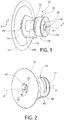
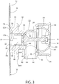
- the fitment 20 basically comprises an assembly of a body or housing 22, a plunger 24, a valve 26, an actuator 28, and a piercing member 30.
- the body 22 is a molded, hollow component having a planar flange 32 configured to be fixedly secured, e.g., welded, to the outer surface of a portion of the wall 14 of the bag 10.
- the portion of the body 22 contiguous with the flange is in the form of a collar 34.
- the collar 34 includes a flange 34A projecting outward from its proximal end.
- the flange 34A is configured to receive a portion of the wall of the box between it and the flange 32, when the fitment is used as a part of a bag-in-box package. It should be pointed out that such use is merely exemplary, such that the fitment of this invention can be used for other applications than bag-in-box.
- the body 22 of the fitment includes a central passageway 36 extending partially through it.
- the passageway is centered about a longitudinally extending axis A.
- the passageway 36 is at the end of the body 22 contiguous with the flange 32 and is open, whereupon a portion 14A of the wall 14 of the bag is in communication with the passageway 36. That portion 14A forms a frangible penetration zone in the bag (i.e., the portion of the bag that will be penetrated by the piercing member 30, as will be described later).
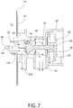
- the open end of the central passageway is best seen in Figs. 2 and 3 and forms the inlet to the fitment through which the liquid in the bag may enter when the frangible penetration zone of the bag is pierced.
- the opposite end of the fitment's body 22 is in the form of a hollow tubular throat 38, which is centered on the axis A and whose inside diameter is larger than the inside diameter of the passageway 36.
- the portion of the body 22 located between the tubular throat 38 and the collar 34 is in the form of an outlet or spout 40.
- the spout 40 constitutes a tubular portion of the body which extends generally perpendicularly to the longitudinal central axis A and has an open end 42 which forms the outlet of the fitment 20.
- a passageway 44 extends through the spout from the open end 42 to the central passageway 36. It is through the spout that the liquid is dispensed from the bag.
- the valve 26 basically comprises a valve member 46 and a valve seat 48.
- the valve member forms an integral portion of the plunger and is preferably molded of a suitable plastic material, e.g., high density polyethylene.
- the valve member is configured to move with the plunger between a closed and open position, and vice versa. The movement of the valve member from the closed position to the open position selectively opens the valve to enable the liquid within the bag to be dispensed from the bag. Conversely, when the valve is moved to its closed state it halts the flow of liquid from the bag.
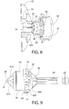
- the valve member is best seen in Figs. 9 and 10 and basically comprises a flanged projection located at the distal end portion of the plunger.
- the valve body has a sloping, e.g., 45 degree, proximally facing surface.
- a peripheral portion of that proximally facing surface is designated by the reference number 46A and cooperates with a portion of the valve seat 48 to form a first circular compression seal when the valve is closed.
- a 90 degree angled annular ledge 46B is located immediately proximally of the sloped surface 46A and forms a second circular compression seal with an associated portion of the valve seat 48 when the valve is closed.
- the distal surface of the valve member is planar and includes two walls 72 and 74 projecting outward therefrom.
- the top surfaces of those walls are coplanar and form pusher surfaces which are arranged to engage the proximal end surface of the piercing member (to be described later) to push the piercing member through the frangible zone 14A of the bag when the fitment is first used.
- the wall 74 includes a recess 76 to serve as a fluid passageway when the walls 72 and 74 are in engagement with the proximal surface of the piercing member.
- the valve seat 48 is best seen in Figs. 3 , 4 , 7 and 8 and is in the form of an annular wall projecting inward radially from the fitment's body 22 into the central passageway 36 at the portion of that passageway that merges with the passageway 44 of the spout 40.
- the annular wall 48 tapers in cross-section to a relatively sharp free edge.
- the valve body is an integral member molded of a suitable plastic, e.g., linear low density polyethylene.
- the inwardly projecting valve seat is somewhat flexible.
- the valve member is configured to be moved between a closed state and an open state, and vice versa, in response to the operation of the actuator.
- the free end of the tapered valve seat 48 will be flexed and disposed in intimate engagement within the annular ledge 46A of the valve member to form the first of the aforementioned compression seals.
- the portion of the valve seat contiguous with its sharpened inner edge will be flexed and in intimate engagement with the contiguous portion sloping proximal surface 46A of the valve member 46 to form the second of the aforementioned compression seals.
- the plunger 24 is an elongated rod-like member of generally cruciform cross-section having a distal end and a proximal end.
- the plunger is disposed within the fitment's central passageway 36 centered along the longitudinal axis A for reciprocating (e.g., sliding) movement therealong.
- the plunger is coupled to the actuator 28 so that manual depression of the actuator by a user causes the plunger to move through the central passageway 36 along the axis A in the distal direction to its extended position, whereupon the valve 26 is open.
- the plunger is also configured to be moved through the central passageway 36 along the central longitudinal axis A in the proximal direction to its retracted position in automatic response to the release of the actuator.
- the valve is closed.
- the proximal end of the plunger 24 is connected to the actuator 28.
- the actuator comprises a depressible member configured to be repeatedly depressed and released to effect its operation.
- the actuator is in the form of a compressible bulb 50 formed of any suitable resilient material, e.g., a thermoplastic polyester elastomer such as HYTREL® of DuPont.
- the compressible bulb is of generally hemispheric shape having an annular peripheral flanged rim 52 ( Figs. 3 and 6 ) which is secured within a correspondingly shaped annular recess 54 ( Fig.3 ) located at the bottom of the throat 28.
- the apex of the compressible bulb 54 is in the form of a slight depression 56.
- the inner surface of the bulb 50 at the location of the depression 56 is in the form of a socket 58 in which the proximal end 60 of the plunger is fixedly secured.
- the bulb 50 is configured to be pressed by a user's finger or thumb to collapse the bulb. This action has the effect of sliding the plunger through the body of the fitment along the axis A to the extended position, whereupon the valve member 46 is brought out of engagement with the valve seat 48, like shown in Fig. 7 , to thereby open the valve 26.
- the compressible bulb is formed of a resilient material, the release of pressure on the bulb by the user enables the bulb to automatically reassume its normal un-collapsed state, whereupon the plunger 24 is carried back to its retracted position, thereby closing the valve 26.
- the piercing member 30 is releasably disposed on the plunger and configured so that when the plunger is initially moved (e.g., slid) to the extended position it will push a tip portion of the piercing member through the frangible zone 14A of the bag's wall 14 to pierce or penetrate that wall portion, whereupon the tip and a contiguous portion of the piercing member will be located within the interior of the bag.
- the plunger will move back to its retracted position, leaving the piercing tip permanently located within the hollow interior of the bag, with another portion of the piercing member permanently located outside the outer surface of the bag.
- the piercing member (which had been temporarily disposed on the valve member of the plunger) will be freed from the plunger so that it will not move with any subsequent movement of the plunger in opening and closing the valve.
- the decoupling of the piercing member from the plunger enables the plunger to move the valve to its open or closed position, without affecting the positioning of the piercing member.
- the valve can be operated independently to enable liquid from the bag to flow out of the fitment's spout when desired and to halt such flow when that action is desired.
- the piercing member 30 is disposed within the central passageway 36 of the body at the location of the distal end-surface of the valve member, i.e., on the planar surfaces of the pusher walls 72 and 74, but is not secured to the valve member.
- the piercing member basically comprises a tubular proximally located section 62 and a pointed distally located tip 64.
- the piercing member is an integral unit molded of the same plastic material as that making up the integral plunger and valve member.
- the tubular section 62 has a central passageway 66 extending therethrough and a flange 68 located at its proximal end.
- the tip 64 comprises an extension of the distal end of the tubular section 62 and includes plural, e.g., 3, legs 64A merging together at a point. The space between adjacent legs is in fluid communication with the passageway 66 of the tubular section 62.
- a shallow annular recess 62A is located in the outer surface of the tubular section 62.
- the flange 68 includes plural notches 68A equidistantly spaced about the periphery of the flange and a planar rear surface 68B. The notches 68A are arranged to receive respective linear rails 70 ( Fig.
- the tip section 64 When the piercing member 30 is in its extended position, its tip section 64 will be located within the bag and the flange 68 of its tubular section 62 will be located outside the outer surface of the wall of the bag contiguous with the frangible penetration zone 14A but still within the central passageway 36, as best seen in Fig 5 . Moreover, a portion of the bag's wall contiguous with the frangible zone will be in engagement with the undercut annular recess 62A as shown in Fig. 4 . This action effectively locks the piercing member in position and thus ensures that the portion of the piercing member within the bag's interior remains therein.
- the length of the plunger 24 is selected so that before first use of the fitment its piercing member 30 is spaced from the frangible zone of the bag's wall and the valve 26 is in its normally closed state, such as shown in Figs. 2 and 3 .
- the movement of the plunger in that direction causes the pusher surfaces of the walls 72 and 74 to engage the planar proximal surface 68A of the piercing member, thereby concomitantly moving the piercing member along the axis A, whereupon the pointed distal section 64 of the piercing member penetrates the wall of the bag at the frangible zone.
- the plunger has been moved to its maximum extended position the piercing member's tip section 64 and the contiguous portion of the tubular section 62 will be located within the bag's interior with its flange 68 located on the outer surface of the wall of the bag. This action permanently locks those portions of the piercing member within the bag's interior.
- the movement of the plunger in the distal direction causes the valve member 46 to move away from its valve seat 48, thereby bringing the fitment's central passageway 36 into fluid communication with the passageway 44 of the spout 40.
- the liquid within the bag which is represented by the arrows in Fig. 7 can flow through those spaces, into the communicating passageway 66 and from there into the central passageway 36 of the fitment 20.
- the liquid can flow outward through the passageway between the recess 76 of the pusher wall 74 and the proximal surface 68A of the piercing member, through the space between the valve member 46 and the valve seat 48 to the passageway 44 in the spout and hence out the spout's open end 42.
- the valve will be maintained in its open state so that the desired amount of liquid can be dispensed through the fitment.
- the actuator has been initially depressed to cause the piercing member to pierce through the frangible zone of the bag so that a portion of the piercing member is permanently located within the bag
- the presence of that portion of the piercing member will hold any wall portion of the bag from the fitment's inlet, thereby ensuring that so long as there is any liquid within the bag it will be enable to flow out when the valve is in the open state.
- the presence of the piercing member within the bag tends to spread open a larger outlet in the bag to enhance flow as compared to merely having a slit in the bag.
- Figs. 12 - 21 there is shown an exemplary package 110 constructed in accordance with this invention.
- the package 110 is arranged for holding and dispensing a flowable material, e.g., a liquid, therefrom by means of a more preferred embodiment of a dispensing fitment 120 constructed in accordance with this invention.
- the package 110 in the form of a bag or pouch which is identical in construction to the bag 10 described heretofore.
- the fitment 120 is fixedly mounted, e.g., welded, on an exterior surface 12 of a portion of one of the walls making up the bag or pouch.
- the fitment 120 is similar in many respects to the fitment 20, except that it does not make use of a separate plunger and piercing member, wherein a portion of that piercing member is permanently located within the interior of the bag after first use of the fitment like the fitment 20. Rather, as will be described later, the fitment 120 makes use of a single piercing member coupled to the actuator, and which piercing member is configured to be extended by depressing the actuator to cause it to pierce through the wall of the bag to enable the contents of the bag, e.g., the liquid, to flow out of the fitment's spout.
- the piercing member automatically retracts out of the bag and back into the fitment upon release of the actuator, whereupon a portion of the piercing member cooperates with two annular, circumferential seals to close the outlet port of the spout and thereby prevent the liquid from flowing or dripping out of the fitment.
- the piercing member includes two piercing portions, to be described later, which are configured to sequentially penetrate the wall of the bag at the penetration zone to facilitate the formation of an opening in the wall of the bag through which the liquid can flow.
- two piercing portions to be described later, which are configured to sequentially penetrate the wall of the bag at the penetration zone to facilitate the formation of an opening in the wall of the bag through which the liquid can flow.
- the piercing member includes a first piercing portion or point which is a leading portion of the piercing member and serves to initially penetrate the wall of the bag.
- the second piercing portion is in the form plural, secondary piercing points followed by elongated cutting edges located proximally of the first piercing point and which serve to produce cross-sectioned flaps from the material forming the wall of the bag at the penetration zone. Those flaps are easily folded away (backward into the interior of the bag) from the small opening created by the first piercing portion as the piercing member is extended into the bag.
- the fitment 120 basically comprises an assembly of a body or housing 122, an actuator 124, and a piercing member 126 ( Fig. 13 ).
- the body 122 is a molded, hollow component which is formed of the same material as the body 22 and has a planar flange 132 configured to be fixedly secured, e.g., welded, to the outer surface of a portion of the wall 14 of the bag 10.
- the portion of the body 122 contiguous with the flange is in the form of a collar 134.
- the collar 134 includes a flange 134A projecting outward from its proximal end.
- the flange 134A is configured to receive a portion of the wall of the box between it and the flange 132, when the fitment 120 is used as a part of a bag-in-box package. It should be pointed out that such use is merely exemplary, such that the fitment 120 can be used for other applications than bag-in-box.
- the body 122 of the fitment 120 includes a central passageway 136 extending partially through it.
- the passageway is centered about a longitudinally extending axis A.
- the passageway 136 is at the end of the body 122 contiguous with the flange 132 and is open, whereupon the frangible penetration zone 14A of the wall 14 of the bag is in communication with the passageway 136.
- the open end of the central passageway 136 is best seen in Figs. 13 and 14 and forms the inlet to the fitment 120 through which the liquid in the bag may enter when the frangible penetration zone of the bag is pierced.
- the opposite end of the fitment's body 122 is in the form of a hollow tubular throat 128, which is centered on the axis A and whose inside diameter is larger than the inside diameter of the passageway 136.
- the actuator 124 which is in the form of a depressable bulb (which will be described later), is located within the throat 128.
- the throat 128 includes a pair of diametrically opposed recesses 128A to facilitate the actuation (depression) of the bulb.
- the throat includes a pair of tabs or flanges 128B projecting outward from the exterior surface of the throat between the recesses.
- the flanges 128B serves as a means which can be held by a user's index finger and middle finger, while the user's thumb presses on the bulb to operate the actuator.
- the portion of the body 122 located between the throat 128 and the collar 134 is in the form of a spout 140. It is through the spout that the liquid is dispensed from the interior 12 of the bag 10.
- the spout 140 constitutes a tubular portion of the body having a passageway 142 which extends generally perpendicularly to the longitudinal central axis A.
- the inner end of the passageway 142 forms the outlet port 142A of the fitment 120 and is in fluid communication with the passageway 136.
- the outer end 142B of the passageway 142 is open so that any liquid from the interior of the bag that enters the outlet port 142A from the passageway 136 will exit the spout at the open end 142B.
- the piercing member 126 which will be described in detail shortly, is located within the central passageway 136 of the body 122 and includes wall portions which are configured to close the outlet port 142A and thus block the spout to prevent any liquid from entering the spout when the piercing member is in its retracted (normal) state, like shown in Fig. 14 .
- those wall portions of the piercing member are configured to engage two annular circumferential seals (also to be described later) in the passageway 136 to ensure that there is no leakage or dripping of the liquid from the spout when the piercing member is in the retracted state.
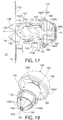
- the piercing member 126 is best seen in Figs. 18 , 20 and 21 and is preferably formed as an integral unit of the same material as that making up the piercing member 30 of the fitment 20.
- the piercing member 126 basically comprises a cylindrical or barrel shaped body having a circular sidewall 150 bounding a hollow interior in which is divided into four passageways 152 by four walls 154.
- the walls 154 extend perpendicularly to each other to form a cruciform wall structure within the bounds of the sidewall 150.
- the passageways 152 extend the length of the sidewall 150 from its open distal end 150A to its open proximal end 150B and thus form paths through the piercing member through which the liquid from the bag can pass when the piercing member is in its extended position, as will be described later.
- the distal end of the walls 154 of the piercing member are in the form of a sharp piercing point or tip 156.
- the tip 156 forms the heretofore mentioned leading portion of the piercing member and is configured to initially penetrate the material, e.g., film, making up the wall 14 of the bag 10 at the penetration zone 14A.
- each of the walls 154 is V-shaped in cross-section to form an elongated sharp cutting edge 154A.
- Each cutting edge 154A tapers toward the piercing tip 156 from the distal end of the sidewall 150 to the tip 156.
- a V-shaped notch 158 is located contiguous proximally to the piercing point 156 in each cutting edge 154A to form respective secondary piercing points 160 at the distal end of each of the cutting edges 154A but proximally of the piercing tip 156.
- the secondary piercing points and the contiguous cutting edges 154 located proximally thereof serve to create the cross-sectioned flaps, designated by the reference number 14B, in the material making up wall of the bag at the frangible penetration zone 14A when the piercing member is extended through the wall of the bag.
- An annular flange 162 ( Figs 20 and 21 ) extends about the periphery of the sidewall 150 at the proximal end of the cutting edges 154.
- the proximal end surface 162A of the flange 162 is conical and tapers downward in the proximal direction.
- the proximal end of the walls 154 of the piercing member 126 terminate at a central rod 164 that extends along the axis A from the point at which the walls 154 merge together.
- the proximal end of the rod 164 includes an annular recess 164A that is configured to be fixedly secured to the actuator 124.
- the actuator 124 comprises a depressible member configured to be repeatedly depressed and released to effect its operation.
- the actuator is in the form of a compressible bulb 166 formed of any suitable resilient material, e.g., the same material as used for bulb 50 of the fitment 20 and is similarly constructed to the bulb 20.
- the bulb 166 is of generally hemispheric shape having an annular peripheral flanged rim 166A ( Figs. 14 , 15 , and 18 ) which is secured within a correspondingly shaped annular recess 128C located at the bottom of the throat 128.
- the apex of the compressible bulb 166 is in the form of a slight depression 166B.
- the inner surface of the bulb at the location of the depression 166B is in the form of a socket 166C in which the proximal end of the rod 164 is fixedly secured.
- the bulb 166 is configured to be depressed by the user to collapse the bulb. This action has the effect of sliding the piercing member 126 through the central passageway 136 in body of the fitment 120 along the axis A to its extended position, whereupon the distal or leading piercing point 156 engages the wall of the bag at the penetration zone 14A to pierce through it. Further inward movement of the piercing member by the depression of the bulb 166 causes the secondary piercing tips 160 to engage the wall of the bag contiguous with the portion that the leading piercing tip 156 engaged, thereby beginning the formation of four, triangularly shaped flaps 14B at the penetration zone.
- the liquid (or other flowable contents of the bag 10) can flow through the now pierced wall 14 of the bag into and through the passageways 152 and out of those passageways at the proximal end of the sidewall 150 in the flow path as shown by the arrows in Fig. 15 .
- the proximal end of the sidewall 150 will be located distally of the outlet port 142A so that the outlet port 142A will be open and the liquid from the passageways 152 can enter it, from whence that liquid will flow through the passageway 142 and out of the open end 142B of the spout.
- the passageway 136 includes a first seal in the form of a circumferential wedge-shaped fin 170 extending inward into the passageway 136 located immediately adjacent the proximal side of the outlet port 142A.
- the fin 170 is shaped somewhat like the valve seat 48 of the fitment 20 and is oriented to that it extends generally perpendicularly to the axis A.
- the seal 170 is configured to form a fluid-tight interface with the proximal end surface 150B of the sidewall 150 when the piercing member is in the retracted position or state, like shown in Fig. 14 .
- the second seal is in the form of a circumferential fin 172 extending inward into the passageway 136 located immediately adjacent the distal side of the outlet port 142A.
- the fin 172 is wedge shaped and oriented so that it extends generally parallel to the axis A.
- the seal 172 is configured to form a fluid-tight interface with the proximal end surface 162A of the annular flange 162 of sidewall 150 when the piercing member is in the retracted position or state, like shown in Fig. 14 .
- the compressible bulb 166 is formed of a resilient material
- the release of pressure on the bulb by the user enables the bulb to automatically reassume (e.g., flex back) its normal un-collapsed state, whereupon the piercing member 126 is carried back to its retracted position. That action brings the proximal end surface 162A of the annular flange 162 of the piercing member into a fluid-tight sealing engagement with the fin 172 and proximal end surface 150B of the sidewall 150 into a fluid-tight sealing engagement with the fin 170, whereupon the outlet port 142A is isolated from the central passageway 136 so that the flow of liquid out of the fitment is halted.
- the fitment 120 When it is desired to initially dispense liquid from the interior of the bag 10, the user merely presses on the depression 166 at the apex of the bulb 166 to collapse the bulb. This action causes the piercing member 126 to slide along the central passageway 136 from the retracted position shown in Fig. 14 , to the extended position shown in Fig. 15 .
- the movement of the piercing member in that direction first causes the pointed distal end 156 of the piercing member to penetrate the wall of the bag at the frangible zone 14A to initially penetrate it, whereupon the secondary piercing points 160 and their adjacent cutting edges 154A cut into the wall material to form the four flaps 14B and to fold those flaps backward into the interior 12 of the bag.
- This action forms a port in the bag (referred to hereinafter as the "film port") through which the liquid can exit the bag.
- the liquid within the bag which is represented by the arrows in Fig. 15 can flow through the film port into and through the passageways 152 in the piercing member, from whence it flows out of the end of those passageways and into the outlet port 142A.
- the fitment 120 From there the liquid flows out of the open end of the spout, as long as the bulb remains depressed by the user. Thus, as long as the bulb remains depressed by the user, the fitment 120 will be maintained in its open state so that a desired amount of liquid can be dispensed through the fitment 120.
- the exemplary embodiments of the fitment as described above are merely examples of many types of fitments that can be constructed in accordance with this invention.
- the annular seals 170 and 172 may form respective portions of the piercing member, rather than forming portions of the body 122.
- other types of sealing arrangements can be used so that when the piercing member is in its retracted position, the flow of liquid through the fitment is stopped, e.g., the outlet port is sealed.
- the piercing member be constructed as described above to produce the heretofore identified flaps, other cutting arrangements can be used in the piercing member to achieve the same end.
Landscapes
- Engineering & Computer Science (AREA)
- Mechanical Engineering (AREA)
- Containers And Packaging Bodies Having A Special Means To Remove Contents (AREA)
Claims (9)
- Raccord (120) pour un emballage (110) contenant un liquide à l'intérieur de celui-ci, ledit raccord (120) étant configuré pour distribuer sélectivement une quantité du liquide depuis l'emballage (110), l'emballage (110) comprenant un sac souple (10) ayant un intérieur creux (12) dans lequel le liquide est disposé et une paroi (14) contigüe à l'intérieur creux (12), ledit raccord (120) comprenant :un corps (122) ayant une portion configurée pour sa fixation à la paroi (14) du sac (10), un passage (136) et un orifice de sortie (142A) en communication avec ledit passage (136) ;un actionneur (124) comprenant un organe configuré pour être enfoncé et relâché à plusieurs reprises ; etun organe de perçage étant configuré pour être déplacé dans une direction à travers ledit passage (136) et à travers une zone de pénétration de ladite paroi (14) dudit sac (10) contigüe audit intérieur creux (12) jusqu'à une position étendue à l'enfoncement dudit actionneur (124) et déplacé dans une seconde direction opposée de retour à travers ladite paroi (14) dudit sac (10) et à travers ledit passage (136) jusqu'à une position complètement rétractée en réponse automatique au relâchement dudit actionneur (124),caractérisé en ce queledit organe de perçage (126) comprend une coupe cylindrique creuse (150) ayant une surface extérieure et étant couplée audit actionneur (124), etl'un dudit passage (136) et de ladite surface extérieure de ladite coupe cylindrique creuse (150) dudit organe de perçage (126) comprenant au moins un joint annulaire (170, 172), ladite surface extérieure dudit organe de perçage (126) et ledit au moins un joint (170, 172) formant une interface étanche au fluide entre eux, ledit organe de perçage (126) incluant une portion bloquant ledit orifice de sortie (142A) lorsque ledit organe de perçage (126) est à ladite position complètement rétractée, et débloquant ledit orifice de sortie (142A) lorsque ledit organe de perçage (126) est déplacé jusqu'à ladite position étendue, en permettant de ce fait au liquide dans l'intérieur creux (12) du sac (10) de s'écouler hors du sac (10) à travers ladite coupe cylindrique creuse (150) dudit organe de perçage (126) et ledit passage (136) jusqu'audit orifice de sortie (142A).
- Raccord selon la revendication 1, dans lequel ledit corps (122) et ladite surface extérieure dudit organe de perçage (126) fournissent ledit passage (136).
- Raccord selon la revendication 2, dans lequel ledit au moins un joint (170, 172) comprend un joint circonférentiel.
- Raccord selon la revendication 3, dans lequel ledit au moins un joint annulaire (170, 172) comprend deux joints circonférentiels, l'un (172) desdits joints circonférentiels étant situé sur un côté dudit orifice de sortie (142A) entre ledit orifice de sortie (142A) et ladite portion dudit corps (122) configurée pour sa fixation à la paroi (14) du sac (10), et l'autre (170) desdits joints circonférentiels étant situé sur un côté opposé dudit orifice de sortie (142A) entre ledit orifice de sortie (142A) et ledit actionneur (124).
- Raccord selon la revendication 1, dans lequel ledit organe de perçage (126) comprend une pointe de perçage avant et plusieurs pointes de perçage secondaires situées à proximité de ladite pointe de perçage avant, ladite pointe de perçage avant étant configurée pour percer à travers ladite zone de pénétration lorsque ledit organe de perçage (126) est d'abord déplacé jusqu'à ladite position étendue, après quoi lesdites pointes de perçage secondaires percent à travers ladite zone de pénétration pour créer des rabats de coupe transversale à la portion de la paroi (14) du sac (10) qui est percée par l'organe de perçage (126), les rabats créés par lesdites pointes de perçage secondaires étant repliables pour faciliter des extensions suivantes de ladite pointe de perçage jusqu'à ladite position étendue et pour fournir un chemin de fluide amélioré à travers la paroi (14) percée de l'emballage (110).
- Raccord selon la revendication 5, dans lequel ledit organe de perçage (126) comprend une portion d'extrémité distale pour maintenir lesdits rabats dans un état plié améliorant le chemin de fluide à travers ladite zone de pénétration lors de déplacements suivants dudit organe de perçage (126) jusqu'à ladite position étendue après le déplacement initial dudit organe de perçage (126) jusqu'à ladite position étendue.
- Raccord selon la revendication 4, dans lequel ledit organe de perçage (126) comprend une pointe de perçage avant et plusieurs pointes de perçage secondaires situées à proximité de ladite pointe de perçage avant, ladite pointe de perçage avant étant configurée pour percer à travers ladite zone de pénétration lorsque ledit organe de perçage (126) est d'abord déplacé jusqu'à ladite position étendue, après quoi lesdites pointes de perçage secondaires percent à travers la paroi (14) du sac (10) pour créer des rabats de coupe transversale à la portion de la paroi (14) du sac (10) qui est percée par l'organe de perçage (126), les rabats créés par lesdites pointes de perçage secondaires étant repliables pour faciliter des extensions suivantes de ladite pointe de perçage jusqu'à ladite position étendue.
- Raccord selon la revendication 1, dans lequel ledit actionneur (124) comprend une ampoule formée d'un matériau élastique.
- Combinaison d'un sac souple (10) et d'un raccord de distribution (120) selon l'une quelconque des revendications précédentes, apte à contenir et distribuer une quantité d'un liquide depuis celle-ci, dans laquelle
ledit sac souple (10) a un intérieur creux (12) dans lequel le liquide est situé et une paroi (14) contigüe audit intérieur creux (12), et
ladite zone de pénétration comprend une portion de la paroi (14) du sac (10) à pénétrer par l'organe de perçage (126) ou ladite zone de pénétration est interposée entre ledit raccord (120) et l'intérieur creux (12) dudit sac (10) ou ladite zone de pénétration isole l'intérieur creux (12) dudit sac (10) du milieu ambiant.
Applications Claiming Priority (3)
| Application Number | Priority Date | Filing Date | Title |
|---|---|---|---|
| US201562189428P | 2015-07-07 | 2015-07-07 | |
| US15/201,767 US9862533B2 (en) | 2015-07-07 | 2016-07-05 | Pierce at first use fluid dispensing valve and flexible package including the same |
| PCT/US2016/041077 WO2017007804A1 (fr) | 2015-07-07 | 2016-07-06 | Robinet avec valve de distribution de liquide et élément de perçage pour sachet |
Publications (2)
| Publication Number | Publication Date |
|---|---|
| EP3319902A1 EP3319902A1 (fr) | 2018-05-16 |
| EP3319902B1 true EP3319902B1 (fr) | 2021-02-17 |
Family
ID=56497868
Family Applications (1)
| Application Number | Title | Priority Date | Filing Date |
|---|---|---|---|
| EP16741451.5A Active EP3319902B1 (fr) | 2015-07-07 | 2016-07-06 | Robinet avec valve de distribution de liquide et membre perforateur pour poche |
Country Status (5)
| Country | Link |
|---|---|
| US (2) | US9862533B2 (fr) |
| EP (1) | EP3319902B1 (fr) |
| CA (1) | CA2991585C (fr) |
| ES (1) | ES2868352T3 (fr) |
| WO (1) | WO2017007804A1 (fr) |
Families Citing this family (17)
| Publication number | Priority date | Publication date | Assignee | Title |
|---|---|---|---|---|
| WO2013119332A2 (fr) | 2012-02-09 | 2013-08-15 | Stout Medical Group, L.P. | Dispositif embolique et procédés d'utilisation |
| CA2943487C (fr) * | 2014-03-25 | 2023-10-24 | The Coca-Cola Company | Buse de distribution a debit eleve et a mousse reduite |
| JP6241969B2 (ja) | 2014-05-28 | 2017-12-06 | ストライカー ヨーロピアン ホールディングス I,エルエルシーStryker European Holdings I,Llc | 血管閉塞器具及びその使用方法 |
| US9862533B2 (en) * | 2015-07-07 | 2018-01-09 | Fres-Co System Usa, Inc. | Pierce at first use fluid dispensing valve and flexible package including the same |
| GB201600894D0 (en) * | 2016-01-18 | 2016-03-02 | Obrist Closures Switzerland | Dispensing closure |
| WO2017210151A1 (fr) * | 2016-05-31 | 2017-12-07 | Carrier Commercial Refrigeration, Inc. | Ensemble soupape pour un récipient de produit alimentaire d'un distributeur de produits alimentaires |
| IT201600123495A1 (it) * | 2016-12-06 | 2017-03-06 | Vitop Moulding Srl | Rubinetto erogatore in materiale plastico per l'erogazione di liquidi da contenitori |
| US10766053B2 (en) * | 2017-01-04 | 2020-09-08 | Red Devil, Inc. | Material dispensing system and method |
| SE543593C2 (sv) | 2017-09-27 | 2021-04-06 | Asept Int Ab | Kopplingsanordning för anslutning till en flexibel container för utmatning av livsmedelsprodukt |
| CN108840296B (zh) * | 2018-08-02 | 2020-03-31 | 浙江大学 | 一种全柔性开瓶器 |
| US11390516B2 (en) | 2020-05-08 | 2022-07-19 | Illinois Tool Works Inc. | Tap assembly |
| US11878903B2 (en) | 2020-06-11 | 2024-01-23 | Illinois Tool Works Inc. | Tap assembly |
| IT202000018889A1 (it) * | 2020-07-31 | 2022-01-31 | Itap Int S R L | Dispositivo di erogazione per contenitori, preferibilmente contenitori flessibili per liquidi, ed assieme comprendente un contenitore e tale dispositivo |
| US11667512B2 (en) * | 2021-03-26 | 2023-06-06 | Henkel Ag & Co. Kgaa | Dispensing system for dispensing a liquid from a replacement container |
| US12054334B2 (en) | 2021-11-19 | 2024-08-06 | Red Devil, Inc. | Sausage package dispensing system, device and method |
| US12344470B1 (en) | 2022-06-16 | 2025-07-01 | Alvaro Parahyba | Condiment package storage and opening device |
| CN116969066B (zh) * | 2023-07-28 | 2026-04-03 | 扎赉诺尔煤业有限责任公司 | 袋装润滑脂用外接导管 |
Citations (1)
| Publication number | Priority date | Publication date | Assignee | Title |
|---|---|---|---|---|
| AU541628B2 (en) * | 1980-07-03 | 1985-01-17 | Wrightcel Limited | Liquid container tap |
Family Cites Families (24)
| Publication number | Priority date | Publication date | Assignee | Title |
|---|---|---|---|---|
| US3696969A (en) | 1969-12-18 | 1972-10-10 | Auberge Corp | Beverage dispensing system |
| US4314654A (en) | 1980-01-29 | 1982-02-09 | Gaubert R J | Bulk liquid container having a pivotable tap |
| IT1141363B (it) | 1980-02-07 | 1986-10-01 | Grace Italiana Spa | Sacca di materiale plastico di tipo perfezionato e metodo di conservazione e distribuzione di liquidi usando la sacca stessa |
| US4440316A (en) | 1980-02-27 | 1984-04-03 | Trinity Associates | Combined piercer and valve for flexible bag |
| US4416395A (en) | 1980-05-05 | 1983-11-22 | Gaubert Rene Jean Marie | Bulk liquid container, tap and tap assembly therefore |
| GB2082152A (en) | 1980-06-24 | 1982-03-03 | A C I Operations | Tap assembly for a container |
| US4469249A (en) | 1980-12-04 | 1984-09-04 | Diemoulders Proprietary Limited | Apparatus for dispensing liquids |
| DK163583A (da) | 1982-04-30 | 1983-10-31 | Diemoulders Pty Ltd | Aftapningshane |
| US4452378A (en) | 1982-06-16 | 1984-06-05 | Trinity Associates | Gussetted bottom pouch |
| US4475670A (en) | 1982-07-09 | 1984-10-09 | Rutter Christopher C | Fluid dispenser |
| CA1206924A (fr) | 1983-03-30 | 1986-07-02 | Paul F. Roos | Robinet |
| US5111970A (en) | 1991-03-12 | 1992-05-12 | Rapak, Inc. | Fluid dispenser having a removable sealing diaphragm |
| GB2263693B (en) * | 1992-01-30 | 1995-11-01 | Waddington & Duval Ltd | Improvements in and relating to dispensing taps |
| AUPP274198A0 (en) | 1998-04-01 | 1998-04-30 | Technosearch Pty. Limited | Nozzle-valve arrangement for liner bags for containers |
| DE19837947A1 (de) | 1998-08-21 | 2000-02-24 | Kunststoffwerk & Formenbau Art | Entnahmevorrichtung für einen Flüssigkeitsbehälter |
| US6131767A (en) | 1998-09-09 | 2000-10-17 | Scholle Corporation | Tap for dispensing fluid |
| US6986324B2 (en) | 2001-10-19 | 2006-01-17 | Hydropac/Lab Products, Inc. | Fluid delivery valve system and method |
| WO2005040034A2 (fr) | 2003-10-23 | 2005-05-06 | Don Miller | Receptacle destine a contenir et distribuer des fluides ensaches |
| GB0505304D0 (en) | 2005-03-15 | 2005-04-20 | Ds Smith Plastics Ltd | Tap for liquid containers |
| US7708164B2 (en) | 2006-11-06 | 2010-05-04 | Fres-Co System Usa, Inc. | Volumetric dispensing fitment and package including the same |
| US8353428B2 (en) * | 2009-07-21 | 2013-01-15 | Fres-Co System Usa, Inc. | Volumetric metering fitment and package including the same |
| US8967430B2 (en) | 2010-04-19 | 2015-03-03 | Illinois Tool Works, Inc. | Tap assembly |
| US8695851B2 (en) | 2010-09-15 | 2014-04-15 | Fres-Co System Usa, Inc. | External fitment with anti-flow blocking feature for aseptic package and method of use |
| US9862533B2 (en) * | 2015-07-07 | 2018-01-09 | Fres-Co System Usa, Inc. | Pierce at first use fluid dispensing valve and flexible package including the same |
-
2016
- 2016-07-05 US US15/201,767 patent/US9862533B2/en active Active
- 2016-07-06 WO PCT/US2016/041077 patent/WO2017007804A1/fr not_active Ceased
- 2016-07-06 CA CA2991585A patent/CA2991585C/fr active Active
- 2016-07-06 ES ES16741451T patent/ES2868352T3/es active Active
- 2016-07-06 EP EP16741451.5A patent/EP3319902B1/fr active Active
-
2017
- 2017-12-06 US US15/833,485 patent/US10301096B2/en active Active
Patent Citations (1)
| Publication number | Priority date | Publication date | Assignee | Title |
|---|---|---|---|---|
| AU541628B2 (en) * | 1980-07-03 | 1985-01-17 | Wrightcel Limited | Liquid container tap |
Also Published As
| Publication number | Publication date |
|---|---|
| CA2991585A1 (fr) | 2017-01-12 |
| ES2868352T3 (es) | 2021-10-21 |
| US9862533B2 (en) | 2018-01-09 |
| CA2991585C (fr) | 2019-05-07 |
| US20180093808A1 (en) | 2018-04-05 |
| US20170008685A1 (en) | 2017-01-12 |
| WO2017007804A1 (fr) | 2017-01-12 |
| EP3319902A1 (fr) | 2018-05-16 |
| US10301096B2 (en) | 2019-05-28 |
Similar Documents
| Publication | Publication Date | Title |
|---|---|---|
| EP3319902B1 (fr) | Robinet avec valve de distribution de liquide et membre perforateur pour poche | |
| US10696535B2 (en) | Pierce at first use dispensing tap for flexible bag with filling gland and bag including the same | |
| CA2711117C (fr) | Accessoire de mesure volumetrique et paquet le comportant | |
| US6447476B1 (en) | Prefilled telescoping ampoule device | |
| US6547101B1 (en) | Multi-chambered ampoule for dispensing a mixture comprising several substances | |
| US2219604A (en) | Dispensing device | |
| US4440316A (en) | Combined piercer and valve for flexible bag | |
| US9149775B2 (en) | Mixer for mixing at least two flowable components and dispensing apparatus | |
| EP1918683A1 (fr) | Dispositif de distribution volumétrique et emballage l'incluant | |
| US10179677B2 (en) | Aseptic package fluid dispensing apparatus and methods of dispensing liquids from flexible packages | |
| US20020166864A1 (en) | Drink spout system | |
| US20020121525A1 (en) | Drink spout system | |
| US10639464B2 (en) | Discharger | |
| EP0046754B1 (fr) | Organe de percage et valve combines pour sac flexible | |
| US10426701B2 (en) | Single use connectors | |
| US6155465A (en) | Dispensing device for a fluid container | |
| US8528783B2 (en) | Sterile dispensing package with coupling insert for receipt of piercing member and method of using the same | |
| GB2335179A (en) | A dispenser having two compartments | |
| KR101890655B1 (ko) | 주사기 방식의 이종 물질 혼합기 및 그 조립방법 | |
| CN205366598U (zh) | 包装瓶 | |
| JPH0236463B2 (fr) | ||
| US20180086544A1 (en) | Telescoping Syringe with One-Way Valve | |
| HK1153450B (en) | Volumetric metering fitment and package including the same |
Legal Events
| Date | Code | Title | Description |
|---|---|---|---|
| STAA | Information on the status of an ep patent application or granted ep patent |
Free format text: STATUS: THE INTERNATIONAL PUBLICATION HAS BEEN MADE |
|
| PUAI | Public reference made under article 153(3) epc to a published international application that has entered the european phase |
Free format text: ORIGINAL CODE: 0009012 |
|
| STAA | Information on the status of an ep patent application or granted ep patent |
Free format text: STATUS: REQUEST FOR EXAMINATION WAS MADE |
|
| 17P | Request for examination filed |
Effective date: 20180122 |
|
| AK | Designated contracting states |
Kind code of ref document: A1 Designated state(s): AL AT BE BG CH CY CZ DE DK EE ES FI FR GB GR HR HU IE IS IT LI LT LU LV MC MK MT NL NO PL PT RO RS SE SI SK SM TR |
|
| AX | Request for extension of the european patent |
Extension state: BA ME |
|
| DAV | Request for validation of the european patent (deleted) | ||
| DAX | Request for extension of the european patent (deleted) | ||
| GRAP | Despatch of communication of intention to grant a patent |
Free format text: ORIGINAL CODE: EPIDOSNIGR1 |
|
| STAA | Information on the status of an ep patent application or granted ep patent |
Free format text: STATUS: GRANT OF PATENT IS INTENDED |
|
| INTG | Intention to grant announced |
Effective date: 20200908 |
|
| RAP1 | Party data changed (applicant data changed or rights of an application transferred) |
Owner name: FRES-CO SYSTEM USA, INC. |
|
| GRAS | Grant fee paid |
Free format text: ORIGINAL CODE: EPIDOSNIGR3 |
|
| GRAA | (expected) grant |
Free format text: ORIGINAL CODE: 0009210 |
|
| STAA | Information on the status of an ep patent application or granted ep patent |
Free format text: STATUS: THE PATENT HAS BEEN GRANTED |
|
| AK | Designated contracting states |
Kind code of ref document: B1 Designated state(s): AL AT BE BG CH CY CZ DE DK EE ES FI FR GB GR HR HU IE IS IT LI LT LU LV MC MK MT NL NO PL PT RO RS SE SI SK SM TR |
|
| REG | Reference to a national code |
Ref country code: GB Ref legal event code: FG4D |
|
| REG | Reference to a national code |
Ref country code: CH Ref legal event code: EP |
|
| REG | Reference to a national code |
Ref country code: DE Ref legal event code: R096 Ref document number: 602016052576 Country of ref document: DE |
|
| REG | Reference to a national code |
Ref country code: AT Ref legal event code: REF Ref document number: 1361214 Country of ref document: AT Kind code of ref document: T Effective date: 20210315 |
|
| REG | Reference to a national code |
Ref country code: IE Ref legal event code: FG4D |
|
| REG | Reference to a national code |
Ref country code: LT Ref legal event code: MG9D |
|
| REG | Reference to a national code |
Ref country code: NL Ref legal event code: MP Effective date: 20210217 |
|
| PG25 | Lapsed in a contracting state [announced via postgrant information from national office to epo] |
Ref country code: FI Free format text: LAPSE BECAUSE OF FAILURE TO SUBMIT A TRANSLATION OF THE DESCRIPTION OR TO PAY THE FEE WITHIN THE PRESCRIBED TIME-LIMIT Effective date: 20210217 Ref country code: HR Free format text: LAPSE BECAUSE OF FAILURE TO SUBMIT A TRANSLATION OF THE DESCRIPTION OR TO PAY THE FEE WITHIN THE PRESCRIBED TIME-LIMIT Effective date: 20210217 Ref country code: GR Free format text: LAPSE BECAUSE OF FAILURE TO SUBMIT A TRANSLATION OF THE DESCRIPTION OR TO PAY THE FEE WITHIN THE PRESCRIBED TIME-LIMIT Effective date: 20210518 Ref country code: NO Free format text: LAPSE BECAUSE OF FAILURE TO SUBMIT A TRANSLATION OF THE DESCRIPTION OR TO PAY THE FEE WITHIN THE PRESCRIBED TIME-LIMIT Effective date: 20210517 Ref country code: PT Free format text: LAPSE BECAUSE OF FAILURE TO SUBMIT A TRANSLATION OF THE DESCRIPTION OR TO PAY THE FEE WITHIN THE PRESCRIBED TIME-LIMIT Effective date: 20210617 Ref country code: BG Free format text: LAPSE BECAUSE OF FAILURE TO SUBMIT A TRANSLATION OF THE DESCRIPTION OR TO PAY THE FEE WITHIN THE PRESCRIBED TIME-LIMIT Effective date: 20210517 Ref country code: LT Free format text: LAPSE BECAUSE OF FAILURE TO SUBMIT A TRANSLATION OF THE DESCRIPTION OR TO PAY THE FEE WITHIN THE PRESCRIBED TIME-LIMIT Effective date: 20210217 |
|
| REG | Reference to a national code |
Ref country code: AT Ref legal event code: MK05 Ref document number: 1361214 Country of ref document: AT Kind code of ref document: T Effective date: 20210217 |
|
| PG25 | Lapsed in a contracting state [announced via postgrant information from national office to epo] |
Ref country code: SE Free format text: LAPSE BECAUSE OF FAILURE TO SUBMIT A TRANSLATION OF THE DESCRIPTION OR TO PAY THE FEE WITHIN THE PRESCRIBED TIME-LIMIT Effective date: 20210217 Ref country code: PL Free format text: LAPSE BECAUSE OF FAILURE TO SUBMIT A TRANSLATION OF THE DESCRIPTION OR TO PAY THE FEE WITHIN THE PRESCRIBED TIME-LIMIT Effective date: 20210217 Ref country code: RS Free format text: LAPSE BECAUSE OF FAILURE TO SUBMIT A TRANSLATION OF THE DESCRIPTION OR TO PAY THE FEE WITHIN THE PRESCRIBED TIME-LIMIT Effective date: 20210217 Ref country code: NL Free format text: LAPSE BECAUSE OF FAILURE TO SUBMIT A TRANSLATION OF THE DESCRIPTION OR TO PAY THE FEE WITHIN THE PRESCRIBED TIME-LIMIT Effective date: 20210217 Ref country code: LV Free format text: LAPSE BECAUSE OF FAILURE TO SUBMIT A TRANSLATION OF THE DESCRIPTION OR TO PAY THE FEE WITHIN THE PRESCRIBED TIME-LIMIT Effective date: 20210217 |
|
| PG25 | Lapsed in a contracting state [announced via postgrant information from national office to epo] |
Ref country code: IS Free format text: LAPSE BECAUSE OF FAILURE TO SUBMIT A TRANSLATION OF THE DESCRIPTION OR TO PAY THE FEE WITHIN THE PRESCRIBED TIME-LIMIT Effective date: 20210617 |
|
| REG | Reference to a national code |
Ref country code: ES Ref legal event code: FG2A Ref document number: 2868352 Country of ref document: ES Kind code of ref document: T3 Effective date: 20211021 |
|
| PG25 | Lapsed in a contracting state [announced via postgrant information from national office to epo] |
Ref country code: EE Free format text: LAPSE BECAUSE OF FAILURE TO SUBMIT A TRANSLATION OF THE DESCRIPTION OR TO PAY THE FEE WITHIN THE PRESCRIBED TIME-LIMIT Effective date: 20210217 Ref country code: CZ Free format text: LAPSE BECAUSE OF FAILURE TO SUBMIT A TRANSLATION OF THE DESCRIPTION OR TO PAY THE FEE WITHIN THE PRESCRIBED TIME-LIMIT Effective date: 20210217 Ref country code: SM Free format text: LAPSE BECAUSE OF FAILURE TO SUBMIT A TRANSLATION OF THE DESCRIPTION OR TO PAY THE FEE WITHIN THE PRESCRIBED TIME-LIMIT Effective date: 20210217 Ref country code: AT Free format text: LAPSE BECAUSE OF FAILURE TO SUBMIT A TRANSLATION OF THE DESCRIPTION OR TO PAY THE FEE WITHIN THE PRESCRIBED TIME-LIMIT Effective date: 20210217 |
|
| REG | Reference to a national code |
Ref country code: DE Ref legal event code: R097 Ref document number: 602016052576 Country of ref document: DE |
|
| PG25 | Lapsed in a contracting state [announced via postgrant information from national office to epo] |
Ref country code: DK Free format text: LAPSE BECAUSE OF FAILURE TO SUBMIT A TRANSLATION OF THE DESCRIPTION OR TO PAY THE FEE WITHIN THE PRESCRIBED TIME-LIMIT Effective date: 20210217 Ref country code: SK Free format text: LAPSE BECAUSE OF FAILURE TO SUBMIT A TRANSLATION OF THE DESCRIPTION OR TO PAY THE FEE WITHIN THE PRESCRIBED TIME-LIMIT Effective date: 20210217 Ref country code: RO Free format text: LAPSE BECAUSE OF FAILURE TO SUBMIT A TRANSLATION OF THE DESCRIPTION OR TO PAY THE FEE WITHIN THE PRESCRIBED TIME-LIMIT Effective date: 20210217 |
|
| PLBE | No opposition filed within time limit |
Free format text: ORIGINAL CODE: 0009261 |
|
| STAA | Information on the status of an ep patent application or granted ep patent |
Free format text: STATUS: NO OPPOSITION FILED WITHIN TIME LIMIT |
|
| 26N | No opposition filed |
Effective date: 20211118 |
|
| PG25 | Lapsed in a contracting state [announced via postgrant information from national office to epo] |
Ref country code: AL Free format text: LAPSE BECAUSE OF FAILURE TO SUBMIT A TRANSLATION OF THE DESCRIPTION OR TO PAY THE FEE WITHIN THE PRESCRIBED TIME-LIMIT Effective date: 20210217 |
|
| PG25 | Lapsed in a contracting state [announced via postgrant information from national office to epo] |
Ref country code: SI Free format text: LAPSE BECAUSE OF FAILURE TO SUBMIT A TRANSLATION OF THE DESCRIPTION OR TO PAY THE FEE WITHIN THE PRESCRIBED TIME-LIMIT Effective date: 20210217 |
|
| REG | Reference to a national code |
Ref country code: CH Ref legal event code: PL |
|
| GBPC | Gb: european patent ceased through non-payment of renewal fee |
Effective date: 20210706 |
|
| PG25 | Lapsed in a contracting state [announced via postgrant information from national office to epo] |
Ref country code: MC Free format text: LAPSE BECAUSE OF FAILURE TO SUBMIT A TRANSLATION OF THE DESCRIPTION OR TO PAY THE FEE WITHIN THE PRESCRIBED TIME-LIMIT Effective date: 20210217 |
|
| REG | Reference to a national code |
Ref country code: BE Ref legal event code: MM Effective date: 20210731 |
|
| PG25 | Lapsed in a contracting state [announced via postgrant information from national office to epo] |
Ref country code: LI Free format text: LAPSE BECAUSE OF NON-PAYMENT OF DUE FEES Effective date: 20210731 Ref country code: GB Free format text: LAPSE BECAUSE OF NON-PAYMENT OF DUE FEES Effective date: 20210706 Ref country code: CH Free format text: LAPSE BECAUSE OF NON-PAYMENT OF DUE FEES Effective date: 20210731 |
|
| PG25 | Lapsed in a contracting state [announced via postgrant information from national office to epo] |
Ref country code: IS Free format text: LAPSE BECAUSE OF FAILURE TO SUBMIT A TRANSLATION OF THE DESCRIPTION OR TO PAY THE FEE WITHIN THE PRESCRIBED TIME-LIMIT Effective date: 20210617 Ref country code: LU Free format text: LAPSE BECAUSE OF NON-PAYMENT OF DUE FEES Effective date: 20210706 |
|
| PG25 | Lapsed in a contracting state [announced via postgrant information from national office to epo] |
Ref country code: IE Free format text: LAPSE BECAUSE OF NON-PAYMENT OF DUE FEES Effective date: 20210706 Ref country code: BE Free format text: LAPSE BECAUSE OF NON-PAYMENT OF DUE FEES Effective date: 20210731 |
|
| PG25 | Lapsed in a contracting state [announced via postgrant information from national office to epo] |
Ref country code: HU Free format text: LAPSE BECAUSE OF FAILURE TO SUBMIT A TRANSLATION OF THE DESCRIPTION OR TO PAY THE FEE WITHIN THE PRESCRIBED TIME-LIMIT; INVALID AB INITIO Effective date: 20160706 |
|
| P01 | Opt-out of the competence of the unified patent court (upc) registered |
Effective date: 20230503 |
|
| PG25 | Lapsed in a contracting state [announced via postgrant information from national office to epo] |
Ref country code: CY Free format text: LAPSE BECAUSE OF FAILURE TO SUBMIT A TRANSLATION OF THE DESCRIPTION OR TO PAY THE FEE WITHIN THE PRESCRIBED TIME-LIMIT Effective date: 20210217 |
|
| PG25 | Lapsed in a contracting state [announced via postgrant information from national office to epo] |
Ref country code: MK Free format text: LAPSE BECAUSE OF FAILURE TO SUBMIT A TRANSLATION OF THE DESCRIPTION OR TO PAY THE FEE WITHIN THE PRESCRIBED TIME-LIMIT Effective date: 20210217 |
|
| PG25 | Lapsed in a contracting state [announced via postgrant information from national office to epo] |
Ref country code: TR Free format text: LAPSE BECAUSE OF FAILURE TO SUBMIT A TRANSLATION OF THE DESCRIPTION OR TO PAY THE FEE WITHIN THE PRESCRIBED TIME-LIMIT Effective date: 20210217 |
|
| PG25 | Lapsed in a contracting state [announced via postgrant information from national office to epo] |
Ref country code: MT Free format text: LAPSE BECAUSE OF FAILURE TO SUBMIT A TRANSLATION OF THE DESCRIPTION OR TO PAY THE FEE WITHIN THE PRESCRIBED TIME-LIMIT Effective date: 20210217 |
|
| PGFP | Annual fee paid to national office [announced via postgrant information from national office to epo] |
Ref country code: ES Payment date: 20250819 Year of fee payment: 10 |
|
| PGFP | Annual fee paid to national office [announced via postgrant information from national office to epo] |
Ref country code: DE Payment date: 20250725 Year of fee payment: 10 |
|
| PGFP | Annual fee paid to national office [announced via postgrant information from national office to epo] |
Ref country code: IT Payment date: 20250731 Year of fee payment: 10 |
|
| PGFP | Annual fee paid to national office [announced via postgrant information from national office to epo] |
Ref country code: FR Payment date: 20250723 Year of fee payment: 10 |