EP3320219B1 - Schraube mit extensometrischen dehnungsmessern zum messen der zug- und/oder scherdehnung der schraube - Google Patents
Schraube mit extensometrischen dehnungsmessern zum messen der zug- und/oder scherdehnung der schraube Download PDFInfo
- Publication number
- EP3320219B1 EP3320219B1 EP16757275.9A EP16757275A EP3320219B1 EP 3320219 B1 EP3320219 B1 EP 3320219B1 EP 16757275 A EP16757275 A EP 16757275A EP 3320219 B1 EP3320219 B1 EP 3320219B1
- Authority
- EP
- European Patent Office
- Prior art keywords
- gauges
- screw
- conical hole
- screw head
- head
- Prior art date
- Legal status (The legal status is an assumption and is not a legal conclusion. Google has not performed a legal analysis and makes no representation as to the accuracy of the status listed.)
- Active
Links
Images

Classifications
-
- F—MECHANICAL ENGINEERING; LIGHTING; HEATING; WEAPONS; BLASTING
- F16—ENGINEERING ELEMENTS AND UNITS; GENERAL MEASURES FOR PRODUCING AND MAINTAINING EFFECTIVE FUNCTIONING OF MACHINES OR INSTALLATIONS; THERMAL INSULATION IN GENERAL
- F16B—DEVICES FOR FASTENING OR SECURING CONSTRUCTIONAL ELEMENTS OR MACHINE PARTS TOGETHER, e.g. NAILS, BOLTS, CIRCLIPS, CLAMPS, CLIPS OR WEDGES; JOINTS OR JOINTING
- F16B31/00—Screwed connections specially modified in view of tensile load; Break-bolts
- F16B31/02—Screwed connections specially modified in view of tensile load; Break-bolts for indicating the attainment of a particular tensile load or limiting tensile load
-
- G—PHYSICS
- G01—MEASURING; TESTING
- G01L—MEASURING FORCE, STRESS, TORQUE, WORK, MECHANICAL POWER, MECHANICAL EFFICIENCY, OR FLUID PRESSURE
- G01L1/00—Measuring force or stress, in general
- G01L1/20—Measuring force or stress, in general by measuring variations in ohmic resistance of solid materials or of electrically-conductive fluids; by making use of electrokinetic cells, i.e. liquid-containing cells wherein an electrical potential is produced or varied upon the application of stress
- G01L1/22—Measuring force or stress, in general by measuring variations in ohmic resistance of solid materials or of electrically-conductive fluids; by making use of electrokinetic cells, i.e. liquid-containing cells wherein an electrical potential is produced or varied upon the application of stress using resistance strain gauges
-
- G—PHYSICS
- G01—MEASURING; TESTING
- G01L—MEASURING FORCE, STRESS, TORQUE, WORK, MECHANICAL POWER, MECHANICAL EFFICIENCY, OR FLUID PRESSURE
- G01L5/00—Apparatus for, or methods of, measuring force, work, mechanical power, or torque, specially adapted for specific purposes
- G01L5/24—Apparatus for, or methods of, measuring force, work, mechanical power, or torque, specially adapted for specific purposes for determining value of torque or twisting moment for tightening a nut or other member which is similarly stressed
-
- F—MECHANICAL ENGINEERING; LIGHTING; HEATING; WEAPONS; BLASTING
- F16—ENGINEERING ELEMENTS AND UNITS; GENERAL MEASURES FOR PRODUCING AND MAINTAINING EFFECTIVE FUNCTIONING OF MACHINES OR INSTALLATIONS; THERMAL INSULATION IN GENERAL
- F16B—DEVICES FOR FASTENING OR SECURING CONSTRUCTIONAL ELEMENTS OR MACHINE PARTS TOGETHER, e.g. NAILS, BOLTS, CIRCLIPS, CLAMPS, CLIPS OR WEDGES; JOINTS OR JOINTING
- F16B31/00—Screwed connections specially modified in view of tensile load; Break-bolts
- F16B31/02—Screwed connections specially modified in view of tensile load; Break-bolts for indicating the attainment of a particular tensile load or limiting tensile load
- F16B2031/022—Screwed connections specially modified in view of tensile load; Break-bolts for indicating the attainment of a particular tensile load or limiting tensile load using an ultrasonic transducer
Definitions
- the present invention relates to the field of tightening screws and door, in particular, a screw having means for knowing the stresses present therein during and / or after tightening.
- the screw may be subjected to shear by the parts to which it is screwed, for example because of a misalignment of the holes in which the screw is screwed or simply solicitations experienced in operation said parts.
- This shear will create shear stresses internal to the screw, which can lead to loosening or, in the worst case, to a rupture of the screw.
- Taiwanese patent TW 1310810 proposes a screw 100, represented on the Figure 1 formed of a threaded cylindrical body 101 and a head 102 having a strain gauge 103 on the lateral wall 104 of said head, the gauge 103 being connected by a cable 105 to processing and display means 106 disposed on the upper face 107 of the screw head 102.
- the end user can thus periodically check that the clamping force remains adequate over time.
- the gauge 103 may be damaged by the clamping means during tightening, such as a key.
- a screw 200 shown on the Figure 2 formed of a threaded cylindrical body 201 and a head 202, comprising at least one strain gauge 203 disposed in an annular groove 204 formed on the lower face 205 of the screw head 202 and adjacent to the cylindrical body 201.
- the gauge or gauges 203 may transmit their measured values to a display device external to the screw, either wired by a cable passing through a hole drilled in the screw head 202, or wirelessly, in which case each gauge 203 incorporates electronics with wireless transmission.
- the present invention aims to solve the problems encountered with the measuring gage screws described above, and thus to provide a screw whose measurement of internal stresses is easier and more reliable for better control in time of the clamping provided by the screws and whose gauges are less likely to be damaged.
- the present invention relates to a screw having a screw head and a threaded cylindrical body, the screw head being provided with strain gauges arranged to deform with the deformation of the screw head, in order to measure a constraint. internal to the screw, said gauges being for this purpose connected or able to be connected to a power supply and to determining means for determining the value of at least one internal stress to the screw from the deformations of said gauges, characterized in that the screw head has, on its upper face, a conical hole whose axis of revolution is aligned with the axis of revolution of the cylindrical body of the screw, and that said gauges are disposed on the wall of the conical hole so as to deform with the deformation of the conical hole, said gauges being oriented so as to measure at least one type of stress internal to the screw selected from the traction and the shear in order to know the forces present in the cylindrical body.
- the solution according to the present invention allows an amplification of the strain of the strain gauges when the screw is under stress, to make more reliable the tensile and / or shear stress measurements, without parasitic measures, the gauges being otherwise protected deterioration.
- the screw head is provided with four strain gauges, said for traction, two gauges are each arranged with their main direction of measurement aligned with a generatrix of said conical hole, the two generatrices being diametrically opposed , and the two other gauges are each arranged with their main measurement direction on a circle formed at the intersection of the wall of said conical hole and an imaginary plane parallel to the upper face of the screw head, and are distributed at equidistant from each other on the circumference of said circle, preferably each being centered on a respective one of said two generatrices, the four gauges being connected by a Wheatstone bridge connected or adapted to be connected to the power supply and to the means of determination, said gauges for measuring the internal tensile stress when shear is not applied in the screw head.
- the screw head is provided with four first strain gauges, known as tensile gauges, and four second strain gauges, also known as tensile gauges, said first gauges are each arranged with their main direction of tension. measurement aligned with a generator of said conical hole and are distributed at a uniform angle between them, and said second gauges are each arranged with their main measurement direction on a circle formed at the intersection of the wall of said conical hole and a plane imaginary parallel to the upper face of the screw head, and are distributed equidistant from each other on the circumference of said circle, said first gauges forming two groups of gauges each comprising two first adjacent gauges connected electrically in series and said second gauges forming two other groups of gauges each comprising two adjacent gauges connected electrically in series, the four groups of gauges being connected by a Wheatstone bridge connected or adapted to be connected to the power supply and the determination means, said first and second gauges for measuring the internal tensile stress in the screw head in order to know the forces present
- the screw head is a hexagonal head and the main direction of measurement of each of said first gauges forms an angle of between 30 and 10 degrees, preferably 15 degrees, with respect to a generator connecting the top of the conical hole to a point of intersection of the generator circle of the conical hole with a line segment connecting two opposing vertices of the hexagon defining the contour of the upper face of the screw head.
- Each second gauge may be located between the main measurement directions of two adjacent first gauges.
- each second gauge is centered on the main direction of measurement of a corresponding one of said first gages.
- the term "centered" means that the main direction of measurement of the first gauge passes through the center of the second gauge, taken in the main direction of measurement of the latter.
- each second gauge is in one piece with the corresponding first gauge, in the form of a double gauge rosette.
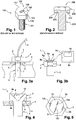
- the screw head is provided with four strain gage gauges, the first and third gages being arranged each parallel to two generatrices located at 45 ° on either side of a main generator of the conical hole, the two other gauges being arranged each parallel to two generatrices located at 45 ° on either side of another main generatrix of the conical hole diametrically opposite said main generator of the conical hole, the four gauges being connected by a Wheatstone bridge connected or adapted to be connected to the power supply and to the determination means, said gauges making it possible to measure the internal shear stress in the screw head in order to know the forces present in the cylindrical body.
- the conical hole has a height less than or equal to that of the screw head.
- the apex angle of the cone is between 70 and 150 degrees, preferably between 75 and 120 degrees, and most preferably is 90 degrees.
- the four shear gauges can be arranged in conjunction with the strain gauges, or be disposed without the strain gauges.
- a groove is formed on the lower surface of the screw head and concentrically and adjacent to the threaded cylindrical body.
- strain gauges may be connected or adapted to be connected to the power supply and the wired determination means.
- the strain gauges may be connected or adapted to be connected to the power supply and the wireless determination means, the gauges being connected to a first near-field communication (NFC) type wireless transmitter / receiver, and the power supply and the determining means being connected to a second NFC-type wireless transmitter / receiver, the first and second transceivers being able to transfer energy and information wirelessly between them.
- NFC near-field communication
- FIG. 3a a principle view of a screw 1 according to the present invention, which has a head 2 and a threaded cylindrical body 3 and which connects a first part 4 having a through hole 5 and a second piece 6 having a threaded blind hole 7 whose thread corresponds to the thread of the threaded body 3.
- the screw 1 can undergo a tensile stress according to the arrow T, a shear stress according to the two-way arrow C, or the two joint stresses.
- the screw 1 comprises a set of strain gauges 8 connected to a power supply and internal stress determining means (s) (not shown).
- the means for determining internal stress are here a voltmeter for measuring the voltage across a Wheatstone bridge, which bridge will be described in more detail in the following description.
- the gauge assembly 8 may be connected to said power supply and to said determining means, either by a wire connection 9, as shown in FIG. Figure 3a either by a wireless link as shown on the Figure 3b .
- the gauge assembly 8 is connected to a first NFC-type wireless transmitter / receiver 8a (near-field communication), and the power supply 8b and the determination means 8c are connected to a second transmitter NFC type 8d wireless receiver, the first and second transceivers 8a, 8d being able to transfer energy and information wirelessly between them.
- the first wireless transmitter / receiver 8a is formed of an amplifier 8e, an NFC chip 8f and a circular antenna 8g surrounding the amplifier 8e, these elements being integrated in the gage assembly 8, and forming the upper part of the latter.
- the second wireless transceiver 8b includes similar elements (not shown).
- the advantage of such wireless communication is to allow, during the lifetime of the screw 1, to place at any time the second transmitter / receiver 8b near the screw 1 to read the value of stress of the screw 1, so as to verify that the latter is tight, and proceed to a tightening in the opposite case.
- the gauge assembly 8 comprises strain gauges which are installed in a conical hole 10 made on the upper face 2a of the head 2 and whose axis of revolution is aligned with that of the cylindrical body 3 , so that the hole 10 is made in the center of the head 2.
- the gauges are fixed in the conical hole 10 by gluing.
- the bonding must be done accurately, so that the deformation of the gauge reflects the deformation of the piece as close as possible.
- the height of the conical hole 10 is here substantially equal to that of the screw head 2, but it can be lower.
- the angle at the top of the conical hole 10 is here 90 degrees. It is emphasized here that this dimension of the conical hole 10 is not limiting and is given solely by way of example, and the appended figures are non-limiting schematic views.
- the conical hole 10 makes it possible to amplify the deformations experienced by the gauges when the screw head 2 is stressed.
- the gauges are disposed on a side face of the screw head, or in a groove formed on its underside.
- Gauges placed in the conical hole 10 will be more deformed than the screw gauges of the prior art, because the bottom of the conical hole 10 will be pulled down in the case of a pull down, and therefore the generatrix of the conical hole 10 will extend more significantly than a side face of the screw head or throat.
- the arrangement of the gauges in the conical hole 10 makes it possible, if necessary, to control the latter in an easy and fast manner, which is not possible with the screws of the prior art.
- the placement of the gauges in the conical hole 10 protects them. Indeed, contrary to the prior art, the gauges can not be damaged by a tool or by too much tightening.
- the first transmitter / receiver when present, may be attached to the wall of the conical hole 10, for example by gluing the edges of the NFC chip against said wall, or otherwise may be glued to the upper face 2a of the head 2, covering the conical hole 10, in the case of screws of smaller size.
- a groove 11 is formed on the lower face 2b of the head 2 and is adjacent to the threaded cylindrical body 3.
- the groove 11 ensures that the support of the screw head 2 is not too close to the threaded cylindrical body 3 and that the deformation of the screw head 2 does not depend on its installation. Indeed, the hole 5 of the support 4 in which the screw passes is generally slightly wider than the screw, to facilitate the passage thereof. There is therefore a clearance between the screw and said hole, and the screw can be positioned offset in said hole, so that the game is not the same over the entire circumference of the hole.
- the bearing surface of the screw head depends on said clearance, and if the bearing surface decreases, the stresses will be greater, and the deformation greater.
- the groove 11 makes it possible to ensure that the same bearing surface 11a bears on the support 4, whatever the position of the screw 1 in the hole 5.
- strain gauges in particular four strain gauges 12a-12d, are fixed in the conical hole 10.
- Each of the gauges 12a-12d has a main direction of measurement, represented by the orientation of the schematic segment forming each of the gauges 12a-12d on the Figures 4 and 5 .
- the main direction of measurement of a gauge is here the longitudinal direction of the gauge, according to which the gauge lengthens or is shortened.
- First two gauges 12a, 12c are each arranged with their main direction of measurement aligned with a generatrix of said conical hole 10, said generatrices being diametrically opposed.
- Two second gauges 12b-12d are each arranged with their main measurement direction on a circle formed at the intersection of the wall of said conical hole 10 and an imaginary plane parallel to the upper face 2a of the screw head 2, and are diametrically opposed.
- the four gauges 12a-12d are electrically connected according to a Wheatstone bridge 13 powered electrically by the two-point power supply 13a and 13b, the Wheatstone bridge 13 being in contact with each other. further connected to the internal stress determining means (s), here a voltmeter, in two points 13c and 13d.
- s internal stress determining means
- R1-R4 are used to define the value of the resistance of the gauges 12a-12d.
- R 1 R 12 at ;
- R 2 R 12 b ;
- R 3 R 12 c ;
- R 4 R 12 d .
- the gauges 12a-12d In the initial state, that is to say when no stress is applied on the screw 1, the gauges 12a-12d have the same resistance value.
- each of the gauges has the same resistance value R in the initial state.
- the resistance value of an extensometry gauge is proportional to its length, and increases as the gauge lengthens and decreases as the gauge narrows.
- the resistance value of the first gages 12a, 12c increases by a given value, for example A
- the resistance value of the second gages 12b, 12d decreases by a given value, for example -B.
- Equation (3) is not satisfied, and a non-zero voltage Vs is measured.
- the tensile stress is related to the voltage Vs by a linear mathematical relation.
- the tensile stress is proportional to the measured voltage.
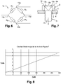
- FIG. 8 An example of a voltage / stress calibration line is shown on the Figure 8 .
- different traction forces are applied known on the screw 1 and the voltage at the Wheatstone bridge 13 is measured for each one.
- the tensile force can be known by knowing the voltage measured at the bridge 13.
- the screw head 2 When applying a shear force alone to the screw 1, the screw head 2 shortens in the shear direction and elongates in the direction orthogonal to the shear. In such a case, the first gauges 12a, 12c are only very slightly deformed and the second gauges 12b, 12d lengthen or shorten depending on the shear direction.
- the gauges 12b and 12d shorten.
- the resistance value of the gauges 12a, 12c is not modified, or will be negligible, and the resistance value of the second gauges 12b, 12d decreases by the same value -C.
- Equation (3) is not satisfied, and a non-zero voltage Vs is measured, whereby shear is measured.
- the screw according to the first embodiment makes it possible to accurately measure a tensile stress, under the condition that no shear is present.
- the two constraints can be exerted, and the second and third embodiments make it possible respectively to measure a tensile stress and a shear stress, even in the case where these two constraints are exerted simultaneously.
- the screw head 2 has eight gauges 14a-14h strain gauge fixed in the conical hole 10.
- Each of the gauges 14a-14h has a main direction of measurement, represented by the orientation of the schematic segment forming each of the gauges 14a-14h on the Figures 9 .
- first gauges 14a-14d are each arranged with their main measurement direction aligned with a generator of said conical hole 10 and are distributed at a uniform angle between them.
- the measuring direction of one of the gauges 14a-14d is at right angles to that of the two gauges 14a-14d which are adjacent to it, when the screw 1 is seen from above, as on the Figure 9 .
- gauges 14e-14h are each arranged with their main direction of measurement on a circle formed at the intersection of the wall of said conical hole 10 and an imaginary plane parallel to the upper face 2a of the screw head 2, and are distributed equidistant from each other on the circumference of said circle.
- the gauges 14e-14h are opposed two by two and one of the gauges 14e-14h is a quarter of a circle of the two gauges 14e-14h which are adjacent thereto.
- the second gauges are fixed perpendicularly to said generators and centered on the latter. In other words, each of the generators crosses a second gauge, perpendicularly and at its center.
- the screw head 2 is a hexagonal head
- the main direction of measurement of each of said first gauges 14a-14d forms an angle of 15 degrees with respect to a generator connecting the apex of the conical hole 10 at a point of intersection of the generator circle of the conical hole 10 with a line segment connecting two opposite vertices of the hexagon defining the contour of the upper face 2a of the screw head 2.
- the direction main measuring one of the first gauges 14a-14d is rotated 15 degrees relative to a straight line passing through two opposite peaks of the hexagon forming the head 2 of the screw 1, taking the top of the conical hole 10 as center of rotation. Since each of the first gauges 14a-14d is 90 degrees from its two adjacent gauges, each of the gauges 14a-14d is oriented at 15 degrees from a straight line passing through two opposite vertices of the hexagon forming the screw head 2 .
- the second gauges 14e-14h are each placed in a zone of the same inertia as the others.
- the second gauges 14e-14h may be arranged near the first gauges 14a-14d, as shown in FIG. Figure 9 , or be in one piece with them, as shown on the Figure 10 where four double gauge rosettes are used.
- the orientation at 15 degrees allows to have the same inertia on each gauge 14a-14h during tightening. Indeed, the fact that the screw head 2 is of hexagonal shape induced during its tightening constraints of different intensities depending on the measurement location.
- the quantity of material to be displaced is greater, and consequently, the moment of inertia to be applied is greater than on a mediator of two opposite sides of the head 2.
- the orientation at 15 degrees thus makes it possible to obtain an identical moment of inertia for each of the gauges 14a-14h.
- the device 8 may also comprise a temperature sensor 14t, which makes it possible to measure the temperature variations of the screw head 2.
- a change in temperature causes expansion or contraction of the material forming the screw head 2, which lengthens or retracts the gauges 12a-12h, and a temperature variation causes a change in the elasticity of the material forming the screw 1.
- the sensitivity of the gauge also depends on the temperature, as the thermal drift of the zero in which the resistance of a gauge increases with temperature, in the absence of stress. It is therefore necessary to take into account the temperature during the measurement.
- the compensation of the resistance value as a function of the temperature can be done in the amplifier 8e, in the case of a wireless measurement, or in the determination means, in the case of a wire measurement. In both cases, the temperature compensation follows a rule established empirically or by learning.
- gauges 14a-14h which gauges 14a-14h are connected in series in pairs, so that the resistance values of these add together, and form groups of gauges connected by a Wheatstone bridge 13.
- Such a device 8 can be implemented, for example, on screws of size M4 according to ISO 4017, namely a screw whose distance between two opposite sides of the hexagon forming the head is 7 mm.
- R 1 R 14 at + R 14 b ;
- R 2 R 14 e + R 14 f ;
- R 3 R 14 c + R 14 d ;
- R 4 R 14 g + R 14 h .
- the first gauges 14a-14d are elongated while the second gauges 14e-14h shorten.
- the resistance value of the first gages 14a-14d increases by a value D
- the resistance value of the second gages 14e-14h decreases by a value -E.
- Equation (3) is not satisfied, and a non-zero voltage Vs is measured, and thus the tensile stress can be deduced therefrom.
- the screw head 2 When applying a shear force alone to the screw 1, the screw head 2 shortens in the shear direction and elongates in the direction orthogonal to the shear. In such a case, the first gauges 14a-14d are only slightly deformed and the second gauges 14e-14h lengthen or shorten depending on the shear direction.
- the gauges 14e and 14g when shear oriented along an axis passing through the gauges 14e and 14g is applied, the latter elongate and the gauges 14f and 14h shorten.
- the resistance value of the first gauges 14a-14d is not modified, that of the gauges 14e and 14g increases and the gauges 14f and 14h decreases.
- the resistance value of the gauges 14e and 14g increases by the same value F and the resistance value of the second gauges 14f and 14h decreases by the same value - G.
- equation (3) is satisfied, and no voltage is measured.
- the screw 1 is tightened with a nut 16 between a first plate 4 having a through hole 5 and a second plate 17 having a through hole 18.
- Each of the gauges 15a-15d has a main direction of measurement, represented by the orientation of the schematic segment forming each of the gauges 15a-15d on the Figures 11 to 13 .
- the first and second gauges 15a, 15b are arranged so that their main directions of measurement are at 45 ° on either side of a first generatrix of the conical hole 10, and the third and fourth gauges 15c, 15d are disposed of the same way at 45 ° on either side of another generatrix diametrically opposed to said first generatrix of the conical hole 10.
- the four gauges 15a-15d are electrically connected according to the Wheatstone bridge 13.
- the screw head 2 When a tensile force T is exerted on the screw 1, in particular during its tightening, the screw head 2 is deformed in such a manner that its upper surface 2a becomes concave. In such a case, the gauges 15a-15d all elongate, and of the same value.
- Equation (3) is satisfied, and a zero voltage Vs is measured.
- the screw according to the third mode of Therefore, the embodiment of the present invention does not make it possible to measure a tensile stress alone.
- the gauges 15a and 15b are elongated and the gauges 15c and 15d shorten.
- the resistance value of the gauges 15a and 15b increases by the same value I and the resistance value of the second gauges 15c and 15d decreases by the same value J.
- the gauges 15a and 15c are elongated and the gauges 15b and 15d shorten.
- the resistance value of the gauges 15a and 15c increases by the same value I and the resistance value of the second gauges 15b and 15d decreases by the same value J.
- the screw 1 according to the third embodiment therefore makes it possible to measure a shear by knowing its direction beforehand in order to measure the stresses it exerts in the screw head 2.
- the screw 1 may comprise both strain gauges 12a-12d or 14a-14h, and shear gauges 15a-15d, each connected by a Wheatstone bridge 13 as described above.
Landscapes
- Engineering & Computer Science (AREA)
- General Engineering & Computer Science (AREA)
- Physics & Mathematics (AREA)
- General Physics & Mathematics (AREA)
- Mechanical Engineering (AREA)
- Force Measurement Appropriate To Specific Purposes (AREA)
Claims (11)
- Schraube (1) mit einem Schraubenkopf (2) und einem gewindeten zylindrischen Körper (3), wobei der Schraubenkopf (2) mit extensometrischen Dehnungsmessern (12a-12d; 14a-14h; 15a-15d) ausgestattet ist, die derart angeordnet sind, dass sie sich mit der Verformung des Schraubenkopfs (2) verformen, um eine interne Beanspruchung der Schraube (1) zu messen, wobei die Dehnungsmesser (12a-12d; 14a-14h; 15a-15d) zu diesem Zweck mit einer elektrischen Versorgung und mit Bestimmungsmitteln verbunden sind oder imstande sind, verbunden zu sein, um den Wert von mindestens einer internen Beanspruchung der Schraube ausgehend von den Verformungen der Dehnungsmesser (12a-12d; 14a-14h; 15a-15d) zu bestimmen, dadurch gekennzeichnet, dass der Schraubenkopf (2) auf seiner oberen Fläche (2a) ein konisches Loch (10) aufweist, dessen Drehachse mit der Drehachse des zylindrischen Körpers (3) der Schraube (1) fluchtet, und dass die Dehnungsmesser (12a-12d; 14a-14h; 15a-15d) auf der Wand des konischen Lochs (10) derart angeordnet sind, dass sie sich mit der Verformung des konischen Lochs (10) verformen, wobei die Dehnungsmesser (12a-12d; 14a-14h; 15a-15d) derart ausgerichtet sind, dass sie mindestens einen Typ einer internen Beanspruchung der Schraube (1) messen, der aus der Zugbeanspruchung und der Scherbeanspruchung ausgewählt ist, um die in dem zylindrischen Körper (3) vorhandenen Kräfte zu kennen.
- Schraube (1) nach Anspruch 1, dadurch gekennzeichnet, dass der Schraubenkopf mit vier ersten extensometrischen Zugbeanspruchungs-Dehnungsmessern (14a-14d) und vier zweiten ebenfalls extensometrischen Zugbeanspruchungs-Dehnungsmessern (14e-14h) ausgestattet ist, wobei die ersten Dehnungsmesser (14a-14d) jeweils mit ihrer Hauptmessrichtung mit einer Mantellinie des konischen Lochs (10) fluchtend angeordnet sind und gemäß einem gleichmäßigen Winkel untereinander verteilt sind, und die zweiten Dehnungsmesser (14e-14h) jeweils mit ihrer Hauptmessrichtung auf einem Kreis angeordnet sind, der am Schnittpunkt der Wand des konischen Lochs (10) und einer imaginären Ebene, die parallel zu der oberen Fläche (2a) des Schraubenkopfs (2) ist, gebildet ist, und gleichbeabstandet voneinander auf dem Umfang des Kreises verteilt sind, wobei die ersten Dehnungsmesser (14a-14d) zwei Dehnungsmessergruppen bilden, umfassend jeweils zwei benachbarte erste Dehnungsmesser (14a-14d), die elektrisch in Reihe verbunden sind, und wobei die zweiten Dehnungsmesser (14e-14h), die zwei andere Dehnungsmessergruppen bilden, jeweils zwei benachbarte zweite Dehnungsmesser (12e-12h) umfassen, die elektrisch in Reihe verbunden sind, wobei die vier Dehnungsmessergruppen durch eine Wheatstonesche Messbrücke (13) verbunden sind, die mit der elektrischen Versorgung und mit den Bestimmungsmitteln verbunden ist oder imstande ist, verbunden zu sein, wobei die ersten und zweiten Dehnungsmesser (14a-14h) das Messen der internen Zugbeanspruchung im Schraubenkopf (2) erlauben, um die in dem zylindrischen Körper (3) vorhandenen Kräfte zu kennen.
- Schraube (1) nach Anspruch 2, dadurch gekennzeichnet, dass der Schraubenkopf (2) ein Sechskantkopf ist und die Hauptmessrichtung jeder der ersten Dehnungsmesser (14a-14d) einen Winkel bildet, der zwischen 30 und 10 Grad, vorzugsweise bei 15 Grad, in Bezug auf eine Mantellinie liegt, welche die Spitze des konischen Lochs (10) an einem Schnittpunkt des Kreises, der das konische Loch (10) bildet, mit einem Segment einer Geraden, welche zwei gegenüberliegende Spitzen des Sechsecks verbindet, welches die Kontur der oberen Fläche (2a) des Schraubenkopfs (2) definiert.
- Schraube (1) nach einem der Ansprüche 2 und 3, dadurch gekennzeichnet, dass jeder zweite Dehnungsmesser (14e-14h) auf der Hauptmessrichtung von einem entsprechenden der ersten Dehnungsmesser (14a-14d) zentriert ist.
- Schraube (1) nach Anspruch 4, dadurch gekennzeichnet, dass jeder zweite Dehnungsmesser (14e-14h) zusammenhängend mit dem entsprechenden ersten Dehnungsmesser (14a-14d) in Form einer doppelten Dehnungsmesserrosette ist.
- Schraube (1) nach einem der Ansprüche 1 bis 5, dadurch gekennzeichnet, dass der Schraubenkopf (2) mit vier extensometrischen Scherbeanspruchungs-Dehnungsmessern (15a-15d) ausgestattet ist, wobei der erste (15a) und dritte Dehnungsmesser (15c) jeweils parallel zu zwei Mantellinien angeordnet ist, die sich bei 45° beiderseits einer Hauptmantellinie des konischen Lochs (10) befinden, wobei die zwei anderen Dehnungsmesser (15b, 15d) jeweils parallel zu zwei Mantellinien angeordnet sind, die sich bei 45° beiderseits einer anderen Hauptmantellinie des konischen Lochs (10) diametral gegenüberliegend zu der anderen Hauptmantellinie des konischen Lochs (10) befinden, wobei die vier Dehnungsmesser (15a-15d) durch eine Wheatstonesche Messbrücke (18) verbunden sind, die mit der elektrischen Versorgung und mit den Bestimmungsmitteln verbunden ist oder imstande ist, verbunden zu sein, wobei die Dehnungsmesser (15a-15d) das Messen der internen Scherbeanspruchung im Schraubenkopf (2) erlauben, um die in dem zylindrischen Körper (3) vorhandenen Kräfte zu kennen.
- Schraube (1) nach Anspruch 1, dadurch gekennzeichnet, dass der Schraubenkopf mit vier extensometrischen Zugbeanspruchungs-Dehnungsmessern (12a-12d) ausgestattet ist, wobei zwei Dehnungsmesser (12a, 12c) jeweils mit ihrer Hauptmessrichtung mit einer Mantellinie des konischen Lochs (10) fluchtend angeordnet sind, wobei die zwei Mantellinien diametral gegenüberliegend sind, und die zwei anderen Dehnungsmesser (12b, 12d) jeweils mit ihrer Hauptmessrichtung auf einem Kreis angeordnet sind, der am Schnittpunkt der Wand des konischen Lochs (10) und einer imaginären Ebene, die parallel zu der oberen Fläche (2a) des Schraubenkopfs (2) ist, gebildet ist, und gleichbeabstandet voneinander auf dem Umfang des Kreises verteilt sind, wobei sie dabei vorzugsweise jeweils auf einer jeweiligen der zwei Mantellinien zentriert sind, wobei die vier Dehnungsmesser (12a-12d) durch eine Wheatstonesche Messbrücke (13) verbunden sind, die mit der elektrischen Versorgung und mit den Bestimmungsmitteln verbunden ist oder imstande ist, verbunden zu sein, wobei die Dehnungsmesser (12a-12d) das Messen der internen Zugbeanspruchung erlauben, wenn keine Scherbeanspruchung in dem Schraubenkopf (2) anliegt.
- Schraube (1) nach einem der Ansprüche 1 bis 7, dadurch gekennzeichnet, dass das konische Loch (10) eine Höhe hat, die kleiner als oder gleich wie die des Schraubenkopfs (2) ist.
- Schraube (1) nach einem der Ansprüche 1 bis 8, dadurch gekennzeichnet, dass der Winkel der Spitze des Konus zwischen 70 und 150 Grad, vorzugsweise zwischen 75 und 120 Grad, liegt und in der am meisten bevorzugten Art 90 Grad beträgt.
- Schraube (1) nach einem der Ansprüche 1 bis 9, dadurch gekennzeichnet, dass eine Nut (11) auf der unteren Oberfläche des Schraubenkopfs (2) ausgebildet und konzentrisch und benachbart zum gewindeten zylindrischen Körper (3) ist.
- Schraube (1) nach einem der Ansprüche 1 bis 10, dadurch gekennzeichnet, dass die extensometrischen Dehnungsmessern (12a-12d; 14a-14h; 15a-15d) mit der elektrischen Versorgung und den Bestimmungsmitteln drahtlos verbunden sind oder imstande sind, verbunden zu sein, wobei die Dehnungsmesser (12a-12d; 14a-14h; 15a-15d) mit einem ersten drahtlosen Sender/Empfänger vom Typ Nahfeldkommunikation (NFC) verbunden sind, und die elektrische Versorgung und die Bestimmungsmittel mit einem zweiten drahtlosen Sender/Empfänger vom Typ NFC verbunden sind, wobei der erste und zweite Sender/Empfänger imstande sind, zwischen sich Energie und Informationen drahtlos zu übertragen.
Applications Claiming Priority (2)
| Application Number | Priority Date | Filing Date | Title |
|---|---|---|---|
| FR1556518A FR3038671B1 (fr) | 2015-07-09 | 2015-07-09 | Vis munie de jauges d'extensometrie pour mesurer la contrainte de traction et/ou de cisaillement subie(s) par la vis |
| PCT/FR2016/051749 WO2017006068A1 (fr) | 2015-07-09 | 2016-07-08 | Vis munie de jauges d'extensometrie pour mesurer la contrainte de traction et/ou de cisaillement subie(s) par la vis |
Publications (2)
| Publication Number | Publication Date |
|---|---|
| EP3320219A1 EP3320219A1 (de) | 2018-05-16 |
| EP3320219B1 true EP3320219B1 (de) | 2019-09-11 |
Family
ID=54066111
Family Applications (1)
| Application Number | Title | Priority Date | Filing Date |
|---|---|---|---|
| EP16757275.9A Active EP3320219B1 (de) | 2015-07-09 | 2016-07-08 | Schraube mit extensometrischen dehnungsmessern zum messen der zug- und/oder scherdehnung der schraube |
Country Status (7)
| Country | Link |
|---|---|
| US (1) | US10731693B2 (de) |
| EP (1) | EP3320219B1 (de) |
| JP (1) | JP6810142B2 (de) |
| CN (1) | CN107850103B (de) |
| ES (1) | ES2760610T3 (de) |
| FR (1) | FR3038671B1 (de) |
| WO (1) | WO2017006068A1 (de) |
Families Citing this family (17)
| Publication number | Priority date | Publication date | Assignee | Title |
|---|---|---|---|---|
| JP6989667B2 (ja) * | 2016-02-12 | 2022-01-05 | 株式会社サンノハシ | 構造物で使われる力学部材 |
| JP6864499B2 (ja) * | 2017-02-28 | 2021-04-28 | 株式会社サンノハシ | 軸力を検出するための締結ボルト装置 |
| US11529208B2 (en) * | 2018-07-19 | 2022-12-20 | Warsaw Orthopedic, Inc. | Break-off set screw |
| US11298162B2 (en) * | 2018-07-19 | 2022-04-12 | Warsaw Orthopedic, Inc. | Load sensing assembly for a spinal implant |
| US12396679B2 (en) | 2018-07-19 | 2025-08-26 | Warsaw Orthopedic, Inc. | System and method for post-operative assessment of spinal motion and implant-based strain correlation |
| US12508097B2 (en) | 2018-07-19 | 2025-12-30 | Warsaw Orthopedic, Inc. | Set screw with strain gauges |
| US11707299B2 (en) * | 2018-07-19 | 2023-07-25 | Warsaw Orthopedic, Inc. | Antenna placement for a digital set screw |
| US10893915B2 (en) * | 2019-05-07 | 2021-01-19 | Warsaw Orthopedic, Inc. | Surgical system and method |
| US12514617B2 (en) | 2018-07-19 | 2026-01-06 | Warsaw Orthopedic, Inc. | Modular set screw design for housing microelectronics |
| US11589905B2 (en) | 2018-07-19 | 2023-02-28 | Warsaw Orthopedic, Inc. | Set screw sensor placement |
| EP3736552A1 (de) * | 2019-05-08 | 2020-11-11 | Hilti Aktiengesellschaft | Scherensensorkragelement |
| CN110543036B (zh) * | 2019-08-15 | 2021-07-06 | Tcl华星光电技术有限公司 | 液晶显示屏 |
| CN112179553B (zh) * | 2020-09-09 | 2021-06-22 | 西南交通大学 | 一种超声同步测量螺栓轴向力和剪切力的方法 |
| PL241682B1 (pl) * | 2020-11-27 | 2022-11-21 | Shm System Spolka Z Ograniczona Odpowiedzialnoscia Spolka Komandytowa | Sposób i detektor do wykrywania momentu uplastycznienia materiału |
| CN113567014A (zh) * | 2021-08-05 | 2021-10-29 | 东风汽车集团股份有限公司 | 车辆底盘紧固连接系统失效检测方法及装置 |
| US12599412B2 (en) | 2022-04-12 | 2026-04-14 | Warsaw Orthopedic, Inc. | Intra-operative options for smart implants |
| US12465408B2 (en) | 2022-04-12 | 2025-11-11 | Warsaw Orthopedic, Inc. | Spinal rod connecting components with active sensing capabilities |
Family Cites Families (18)
| Publication number | Priority date | Publication date | Assignee | Title |
|---|---|---|---|---|
| US2600029A (en) * | 1946-11-12 | 1952-06-10 | Gerotor May Corp | Stress indicating bolt or stud |
| US3201977A (en) * | 1961-02-20 | 1965-08-24 | Kutsay Ali Umit | Strain gauge |
| USRE30183E (en) * | 1976-09-24 | 1980-01-08 | Radio-frequency tuned-circuit microdisplacement transducer | |
| SE424573B (sv) * | 1978-11-13 | 1982-07-26 | Atlas Copco Ab | Bult for axialkraftoverforing |
| DE4410722A1 (de) * | 1994-03-28 | 1995-10-05 | Bosch Gmbh Robert | Vorrichtung zur berührungsfreien Bestimmung der Vorspannkraft |
| US7441462B2 (en) * | 2001-01-29 | 2008-10-28 | Innovation Plus, Llc | Load indicating member with identifying element |
| CA2567475C (en) * | 2004-05-19 | 2013-08-06 | Vibrosystm Inc. | Shear component breakage detection |
| US7293466B2 (en) * | 2005-07-19 | 2007-11-13 | Hitachi, Ltd. | Bolt with function of measuring strain |
| TW200840950A (en) * | 2007-04-04 | 2008-10-16 | Kabo Tool Co | Engineering screwing device with torque display |
| US20080253858A1 (en) * | 2007-04-12 | 2008-10-16 | Chih-Ching Hsieh | Screwing device with function of twisting force measurement |
| US8521448B1 (en) * | 2009-10-21 | 2013-08-27 | The Boeing Company | Structural analysis using measurement of fastener parameters |
| TWI334464B (en) * | 2007-12-13 | 2010-12-11 | Ind Tech Res Inst | Fixing element and inspection system thereof |
| JP2010053927A (ja) * | 2008-08-27 | 2010-03-11 | Asahi Electric Works Ltd | 締め付け装置およびその軸力検出システム |
| CN101354300A (zh) * | 2008-09-19 | 2009-01-28 | 清华大学 | 螺栓受力检测装置 |
| US8584957B2 (en) * | 2012-01-23 | 2013-11-19 | Silicon Valley Microe Corp. | Intelligent fastener |
| TWI495800B (zh) * | 2013-03-06 | 2015-08-11 | Kabo Tool Co | A screw with a locking force |
| JP6324405B2 (ja) * | 2013-11-22 | 2018-05-16 | 株式会社サンノハシ | ボルト、ナット、および歪測定システム |
| CN203745120U (zh) * | 2014-01-06 | 2014-07-30 | 潍柴动力股份有限公司 | 螺栓受力检测装置 |
-
2015
- 2015-07-09 FR FR1556518A patent/FR3038671B1/fr not_active Expired - Fee Related
-
2016
- 2016-07-08 CN CN201680039781.2A patent/CN107850103B/zh active Active
- 2016-07-08 US US15/742,090 patent/US10731693B2/en active Active
- 2016-07-08 WO PCT/FR2016/051749 patent/WO2017006068A1/fr not_active Ceased
- 2016-07-08 JP JP2018520032A patent/JP6810142B2/ja active Active
- 2016-07-08 ES ES16757275T patent/ES2760610T3/es active Active
- 2016-07-08 EP EP16757275.9A patent/EP3320219B1/de active Active
Non-Patent Citations (1)
| Title |
|---|
| None * |
Also Published As
| Publication number | Publication date |
|---|---|
| JP2018527585A (ja) | 2018-09-20 |
| CN107850103B (zh) | 2019-09-13 |
| US20180195547A1 (en) | 2018-07-12 |
| EP3320219A1 (de) | 2018-05-16 |
| FR3038671B1 (fr) | 2017-07-21 |
| FR3038671A1 (fr) | 2017-01-13 |
| JP6810142B2 (ja) | 2021-01-06 |
| US10731693B2 (en) | 2020-08-04 |
| WO2017006068A1 (fr) | 2017-01-12 |
| ES2760610T3 (es) | 2020-05-14 |
| CN107850103A (zh) | 2018-03-27 |
Similar Documents
| Publication | Publication Date | Title |
|---|---|---|
| EP3320219B1 (de) | Schraube mit extensometrischen dehnungsmessern zum messen der zug- und/oder scherdehnung der schraube | |
| EP2883784B1 (de) | Dynamometrisches Fahrradpedal | |
| EP0611193B1 (de) | Vorrichtung zum Messen der Beanspruchung auf mechanischen Teilen und Verfahren zum Binden | |
| WO1984002577A1 (fr) | Procede ultrasonique de mesure de contrainte dans un boulon ou piece analogue, adapte a ce procede | |
| NO330778B1 (no) | Fremgangsmate og anordning for lastindikerende festesystemer | |
| FR2852879A1 (fr) | Cle a serrage controle | |
| CA2006937A1 (fr) | Capteur extensometrique de mesure de contraintes agissant sur un element de forage et dispositif de montage d'un tel capteur | |
| EP1488192A2 (de) | Ausdehnungsmesssonde | |
| FR2799837A1 (fr) | Procede et dispositif de mesure d'efforts en presence d'une pression exterieure | |
| EP1883799A1 (de) | Ring zur messung der seitlichen verformung eines prüflings in uniaxialen oder triaxialen kompressionstests | |
| EP3289329A1 (de) | Drehmomentmesser zur messung von verformungen | |
| FR2972255A1 (fr) | Methode et dispositif de serrage d'un ensemble visse | |
| EP0766077A1 (de) | Kraftsensor zur Kontrolle des Festziehens von verschraubten Teilen | |
| WO2017203188A1 (fr) | Capteur pour mesurer une force de serrage appliquée sur un organe d'assemblage a vis | |
| CH692559A5 (fr) | Capteur d'effort de compression. | |
| EP2384970A1 (de) | Flugsteuerungssystem, dieses System enthaltende Flugzeugsteuerungsvorrichtung, und Verwendung dieses Systems | |
| FR3012605A1 (fr) | Dispositif de mesure deportee de deformation en torsion et/ou en traction | |
| EP3428055B1 (de) | Verfahren und vorrichtung zur bestimmung der richtung und amplitude einer angelegten kraft auf eine antriebsgondel für ein boot | |
| FR2911528A1 (fr) | Outil de vissage incluant un ou plusieurs capteurs de couple montes pour mesurer des deformations dans un plan perpendiculaire a un axe de revolution, et support de capteur correspondant | |
| EP3388808B1 (de) | Druckerfassungsvorrichtung mit mechanischer entkoppelung | |
| FR3047681A1 (fr) | Presse de serrage mecanique a dynamometre | |
| FR3005731A1 (fr) | Capteur de choc destructif | |
| FR2708101A1 (fr) | Capteur de force à deux voies et application notamment à la mesure d'un torseur de forces. | |
| WO2024038235A1 (fr) | Vis d'assemblage instrumentee | |
| EP0026682A1 (de) | Hydraulischer Kraftmesser |
Legal Events
| Date | Code | Title | Description |
|---|---|---|---|
| STAA | Information on the status of an ep patent application or granted ep patent |
Free format text: STATUS: THE INTERNATIONAL PUBLICATION HAS BEEN MADE |
|
| PUAI | Public reference made under article 153(3) epc to a published international application that has entered the european phase |
Free format text: ORIGINAL CODE: 0009012 |
|
| STAA | Information on the status of an ep patent application or granted ep patent |
Free format text: STATUS: REQUEST FOR EXAMINATION WAS MADE |
|
| 17P | Request for examination filed |
Effective date: 20180209 |
|
| AK | Designated contracting states |
Kind code of ref document: A1 Designated state(s): AL AT BE BG CH CY CZ DE DK EE ES FI FR GB GR HR HU IE IS IT LI LT LU LV MC MK MT NL NO PL PT RO RS SE SI SK SM TR |
|
| AX | Request for extension of the european patent |
Extension state: BA ME |
|
| RIN1 | Information on inventor provided before grant (corrected) |
Inventor name: DEMEOCQ, ETIENNE |
|
| DAV | Request for validation of the european patent (deleted) | ||
| DAX | Request for extension of the european patent (deleted) | ||
| GRAP | Despatch of communication of intention to grant a patent |
Free format text: ORIGINAL CODE: EPIDOSNIGR1 |
|
| STAA | Information on the status of an ep patent application or granted ep patent |
Free format text: STATUS: GRANT OF PATENT IS INTENDED |
|
| INTG | Intention to grant announced |
Effective date: 20190305 |
|
| RAP1 | Party data changed (applicant data changed or rights of an application transferred) |
Owner name: TEXYS.FR Owner name: DEMEOCQ, ETIENNE |
|
| GRAS | Grant fee paid |
Free format text: ORIGINAL CODE: EPIDOSNIGR3 |
|
| GRAA | (expected) grant |
Free format text: ORIGINAL CODE: 0009210 |
|
| STAA | Information on the status of an ep patent application or granted ep patent |
Free format text: STATUS: THE PATENT HAS BEEN GRANTED |
|
| AK | Designated contracting states |
Kind code of ref document: B1 Designated state(s): AL AT BE BG CH CY CZ DE DK EE ES FI FR GB GR HR HU IE IS IT LI LT LU LV MC MK MT NL NO PL PT RO RS SE SI SK SM TR |
|
| REG | Reference to a national code |
Ref country code: GB Ref legal event code: FG4D Free format text: NOT ENGLISH |
|
| REG | Reference to a national code |
Ref country code: CH Ref legal event code: EP |
|
| REG | Reference to a national code |
Ref country code: AT Ref legal event code: REF Ref document number: 1178820 Country of ref document: AT Kind code of ref document: T Effective date: 20190915 |
|
| REG | Reference to a national code |
Ref country code: DE Ref legal event code: R096 Ref document number: 602016020476 Country of ref document: DE Ref country code: IE Ref legal event code: FG4D Free format text: LANGUAGE OF EP DOCUMENT: FRENCH |
|
| REG | Reference to a national code |
Ref country code: NL Ref legal event code: MP Effective date: 20190911 |
|
| REG | Reference to a national code |
Ref country code: LT Ref legal event code: MG4D |
|
| PG25 | Lapsed in a contracting state [announced via postgrant information from national office to epo] |
Ref country code: LT Free format text: LAPSE BECAUSE OF FAILURE TO SUBMIT A TRANSLATION OF THE DESCRIPTION OR TO PAY THE FEE WITHIN THE PRESCRIBED TIME-LIMIT Effective date: 20190911 Ref country code: HR Free format text: LAPSE BECAUSE OF FAILURE TO SUBMIT A TRANSLATION OF THE DESCRIPTION OR TO PAY THE FEE WITHIN THE PRESCRIBED TIME-LIMIT Effective date: 20190911 Ref country code: BG Free format text: LAPSE BECAUSE OF FAILURE TO SUBMIT A TRANSLATION OF THE DESCRIPTION OR TO PAY THE FEE WITHIN THE PRESCRIBED TIME-LIMIT Effective date: 20191211 Ref country code: SE Free format text: LAPSE BECAUSE OF FAILURE TO SUBMIT A TRANSLATION OF THE DESCRIPTION OR TO PAY THE FEE WITHIN THE PRESCRIBED TIME-LIMIT Effective date: 20190911 Ref country code: NO Free format text: LAPSE BECAUSE OF FAILURE TO SUBMIT A TRANSLATION OF THE DESCRIPTION OR TO PAY THE FEE WITHIN THE PRESCRIBED TIME-LIMIT Effective date: 20191211 Ref country code: FI Free format text: LAPSE BECAUSE OF FAILURE TO SUBMIT A TRANSLATION OF THE DESCRIPTION OR TO PAY THE FEE WITHIN THE PRESCRIBED TIME-LIMIT Effective date: 20190911 |
|
| PG25 | Lapsed in a contracting state [announced via postgrant information from national office to epo] |
Ref country code: RS Free format text: LAPSE BECAUSE OF FAILURE TO SUBMIT A TRANSLATION OF THE DESCRIPTION OR TO PAY THE FEE WITHIN THE PRESCRIBED TIME-LIMIT Effective date: 20190911 Ref country code: GR Free format text: LAPSE BECAUSE OF FAILURE TO SUBMIT A TRANSLATION OF THE DESCRIPTION OR TO PAY THE FEE WITHIN THE PRESCRIBED TIME-LIMIT Effective date: 20191212 Ref country code: LV Free format text: LAPSE BECAUSE OF FAILURE TO SUBMIT A TRANSLATION OF THE DESCRIPTION OR TO PAY THE FEE WITHIN THE PRESCRIBED TIME-LIMIT Effective date: 20190911 Ref country code: AL Free format text: LAPSE BECAUSE OF FAILURE TO SUBMIT A TRANSLATION OF THE DESCRIPTION OR TO PAY THE FEE WITHIN THE PRESCRIBED TIME-LIMIT Effective date: 20190911 |
|
| REG | Reference to a national code |
Ref country code: AT Ref legal event code: MK05 Ref document number: 1178820 Country of ref document: AT Kind code of ref document: T Effective date: 20190911 |
|
| PG25 | Lapsed in a contracting state [announced via postgrant information from national office to epo] |
Ref country code: RO Free format text: LAPSE BECAUSE OF FAILURE TO SUBMIT A TRANSLATION OF THE DESCRIPTION OR TO PAY THE FEE WITHIN THE PRESCRIBED TIME-LIMIT Effective date: 20190911 Ref country code: PT Free format text: LAPSE BECAUSE OF FAILURE TO SUBMIT A TRANSLATION OF THE DESCRIPTION OR TO PAY THE FEE WITHIN THE PRESCRIBED TIME-LIMIT Effective date: 20200113 Ref country code: EE Free format text: LAPSE BECAUSE OF FAILURE TO SUBMIT A TRANSLATION OF THE DESCRIPTION OR TO PAY THE FEE WITHIN THE PRESCRIBED TIME-LIMIT Effective date: 20190911 Ref country code: AT Free format text: LAPSE BECAUSE OF FAILURE TO SUBMIT A TRANSLATION OF THE DESCRIPTION OR TO PAY THE FEE WITHIN THE PRESCRIBED TIME-LIMIT Effective date: 20190911 Ref country code: NL Free format text: LAPSE BECAUSE OF FAILURE TO SUBMIT A TRANSLATION OF THE DESCRIPTION OR TO PAY THE FEE WITHIN THE PRESCRIBED TIME-LIMIT Effective date: 20190911 Ref country code: PL Free format text: LAPSE BECAUSE OF FAILURE TO SUBMIT A TRANSLATION OF THE DESCRIPTION OR TO PAY THE FEE WITHIN THE PRESCRIBED TIME-LIMIT Effective date: 20190911 |
|
| REG | Reference to a national code |
Ref country code: ES Ref legal event code: FG2A Ref document number: 2760610 Country of ref document: ES Kind code of ref document: T3 Effective date: 20200514 |
|
| PG25 | Lapsed in a contracting state [announced via postgrant information from national office to epo] |
Ref country code: IS Free format text: LAPSE BECAUSE OF FAILURE TO SUBMIT A TRANSLATION OF THE DESCRIPTION OR TO PAY THE FEE WITHIN THE PRESCRIBED TIME-LIMIT Effective date: 20200224 Ref country code: SK Free format text: LAPSE BECAUSE OF FAILURE TO SUBMIT A TRANSLATION OF THE DESCRIPTION OR TO PAY THE FEE WITHIN THE PRESCRIBED TIME-LIMIT Effective date: 20190911 Ref country code: SM Free format text: LAPSE BECAUSE OF FAILURE TO SUBMIT A TRANSLATION OF THE DESCRIPTION OR TO PAY THE FEE WITHIN THE PRESCRIBED TIME-LIMIT Effective date: 20190911 Ref country code: CZ Free format text: LAPSE BECAUSE OF FAILURE TO SUBMIT A TRANSLATION OF THE DESCRIPTION OR TO PAY THE FEE WITHIN THE PRESCRIBED TIME-LIMIT Effective date: 20190911 |
|
| REG | Reference to a national code |
Ref country code: DE Ref legal event code: R097 Ref document number: 602016020476 Country of ref document: DE |
|
| PLBE | No opposition filed within time limit |
Free format text: ORIGINAL CODE: 0009261 |
|
| STAA | Information on the status of an ep patent application or granted ep patent |
Free format text: STATUS: NO OPPOSITION FILED WITHIN TIME LIMIT |
|
| PG2D | Information on lapse in contracting state deleted |
Ref country code: IS |
|
| PG25 | Lapsed in a contracting state [announced via postgrant information from national office to epo] |
Ref country code: DK Free format text: LAPSE BECAUSE OF FAILURE TO SUBMIT A TRANSLATION OF THE DESCRIPTION OR TO PAY THE FEE WITHIN THE PRESCRIBED TIME-LIMIT Effective date: 20190911 Ref country code: IS Free format text: LAPSE BECAUSE OF FAILURE TO SUBMIT A TRANSLATION OF THE DESCRIPTION OR TO PAY THE FEE WITHIN THE PRESCRIBED TIME-LIMIT Effective date: 20200112 |
|
| 26N | No opposition filed |
Effective date: 20200615 |
|
| PG25 | Lapsed in a contracting state [announced via postgrant information from national office to epo] |
Ref country code: SI Free format text: LAPSE BECAUSE OF FAILURE TO SUBMIT A TRANSLATION OF THE DESCRIPTION OR TO PAY THE FEE WITHIN THE PRESCRIBED TIME-LIMIT Effective date: 20190911 |
|
| PG25 | Lapsed in a contracting state [announced via postgrant information from national office to epo] |
Ref country code: MC Free format text: LAPSE BECAUSE OF FAILURE TO SUBMIT A TRANSLATION OF THE DESCRIPTION OR TO PAY THE FEE WITHIN THE PRESCRIBED TIME-LIMIT Effective date: 20190911 |
|
| REG | Reference to a national code |
Ref country code: CH Ref legal event code: PL |
|
| REG | Reference to a national code |
Ref country code: BE Ref legal event code: MM Effective date: 20200731 |
|
| PG25 | Lapsed in a contracting state [announced via postgrant information from national office to epo] |
Ref country code: LU Free format text: LAPSE BECAUSE OF NON-PAYMENT OF DUE FEES Effective date: 20200708 Ref country code: LI Free format text: LAPSE BECAUSE OF NON-PAYMENT OF DUE FEES Effective date: 20200731 Ref country code: CH Free format text: LAPSE BECAUSE OF NON-PAYMENT OF DUE FEES Effective date: 20200731 |
|
| PG25 | Lapsed in a contracting state [announced via postgrant information from national office to epo] |
Ref country code: BE Free format text: LAPSE BECAUSE OF NON-PAYMENT OF DUE FEES Effective date: 20200731 |
|
| PG25 | Lapsed in a contracting state [announced via postgrant information from national office to epo] |
Ref country code: IE Free format text: LAPSE BECAUSE OF NON-PAYMENT OF DUE FEES Effective date: 20200708 |
|
| PG25 | Lapsed in a contracting state [announced via postgrant information from national office to epo] |
Ref country code: TR Free format text: LAPSE BECAUSE OF FAILURE TO SUBMIT A TRANSLATION OF THE DESCRIPTION OR TO PAY THE FEE WITHIN THE PRESCRIBED TIME-LIMIT Effective date: 20190911 Ref country code: MT Free format text: LAPSE BECAUSE OF FAILURE TO SUBMIT A TRANSLATION OF THE DESCRIPTION OR TO PAY THE FEE WITHIN THE PRESCRIBED TIME-LIMIT Effective date: 20190911 Ref country code: CY Free format text: LAPSE BECAUSE OF FAILURE TO SUBMIT A TRANSLATION OF THE DESCRIPTION OR TO PAY THE FEE WITHIN THE PRESCRIBED TIME-LIMIT Effective date: 20190911 |
|
| PG25 | Lapsed in a contracting state [announced via postgrant information from national office to epo] |
Ref country code: MK Free format text: LAPSE BECAUSE OF FAILURE TO SUBMIT A TRANSLATION OF THE DESCRIPTION OR TO PAY THE FEE WITHIN THE PRESCRIBED TIME-LIMIT Effective date: 20190911 |
|
| REG | Reference to a national code |
Ref country code: ES Ref legal event code: PC2A Owner name: TEXYS INTERNATIONAL Effective date: 20221019 |
|
| REG | Reference to a national code |
Ref country code: DE Ref legal event code: R081 Ref document number: 602016020476 Country of ref document: DE Owner name: TEXYS INTERNATIONAL, FR Free format text: FORMER OWNERS: DEMEOCQ, ETIENNE, ALLIGNY-COSNE, FR; TEXYS.FR, VARENNES-VAUZELLES, FR Ref country code: DE Ref legal event code: R081 Ref document number: 602016020476 Country of ref document: DE Owner name: DEMEOCQ, ETIENNE, FR Free format text: FORMER OWNERS: DEMEOCQ, ETIENNE, ALLIGNY-COSNE, FR; TEXYS.FR, VARENNES-VAUZELLES, FR |
|
| PGFP | Annual fee paid to national office [announced via postgrant information from national office to epo] |
Ref country code: ES Payment date: 20250806 Year of fee payment: 10 |
|
| PGFP | Annual fee paid to national office [announced via postgrant information from national office to epo] |
Ref country code: DE Payment date: 20250725 Year of fee payment: 10 |
|
| PGFP | Annual fee paid to national office [announced via postgrant information from national office to epo] |
Ref country code: IT Payment date: 20250723 Year of fee payment: 10 |
|
| PGFP | Annual fee paid to national office [announced via postgrant information from national office to epo] |
Ref country code: GB Payment date: 20250717 Year of fee payment: 10 |
|
| PGFP | Annual fee paid to national office [announced via postgrant information from national office to epo] |
Ref country code: FR Payment date: 20250704 Year of fee payment: 10 |