EP3320316B1 - Modularer kalibrierrotor für eine horizontale auswuchtvorrichtung - Google Patents
Modularer kalibrierrotor für eine horizontale auswuchtvorrichtung Download PDFInfo
- Publication number
- EP3320316B1 EP3320316B1 EP16744441.3A EP16744441A EP3320316B1 EP 3320316 B1 EP3320316 B1 EP 3320316B1 EP 16744441 A EP16744441 A EP 16744441A EP 3320316 B1 EP3320316 B1 EP 3320316B1
- Authority
- EP
- European Patent Office
- Prior art keywords
- rotor
- barrel
- adapter
- calibration
- bearing surface
- Prior art date
- Legal status (The legal status is an assumption and is not a legal conclusion. Google has not performed a legal analysis and makes no representation as to the accuracy of the status listed.)
- Active
Links
Images



Classifications
-
- G—PHYSICS
- G01—MEASURING; TESTING
- G01M—TESTING STATIC OR DYNAMIC BALANCE OF MACHINES OR STRUCTURES; TESTING OF STRUCTURES OR APPARATUS, NOT OTHERWISE PROVIDED FOR
- G01M1/00—Testing static or dynamic balance of machines or structures
- G01M1/02—Details of balancing machines or devices
- G01M1/04—Adaptation of bearing support assemblies for receiving the body to be tested
-
- G—PHYSICS
- G01—MEASURING; TESTING
- G01M—TESTING STATIC OR DYNAMIC BALANCE OF MACHINES OR STRUCTURES; TESTING OF STRUCTURES OR APPARATUS, NOT OTHERWISE PROVIDED FOR
- G01M1/00—Testing static or dynamic balance of machines or structures
- G01M1/02—Details of balancing machines or devices
-
- G—PHYSICS
- G01—MEASURING; TESTING
- G01M—TESTING STATIC OR DYNAMIC BALANCE OF MACHINES OR STRUCTURES; TESTING OF STRUCTURES OR APPARATUS, NOT OTHERWISE PROVIDED FOR
- G01M1/00—Testing static or dynamic balance of machines or structures
- G01M1/02—Details of balancing machines or devices
- G01M1/06—Adaptation of drive assemblies for receiving the body to be tested
Definitions
- the invention relates to a modular calibration rotor for calibrating a horizontal balancer, in particular a rotor for calibrating different types of balancing machines of the type used in the field of aircraft engines for balancing purposes. turbomachine rotors.
- a turbomachine comprises rotors which are either monobloc or more generally consist of a plurality of elements manufactured separately and assembled mechanically.
- a gas turbine engine thus comprises one or more rotor assemblies each consisting of a compressor and a turbine. To provide flexibility in engine maintenance, the assemblies consist of interchangeable modules.
- a compressor module is associated with a turbine module.
- a balancing rotor For the calibration of a balancer, a balancing rotor is conventionally used adapted to the particular type of balancer to be calibrated.
- a balancing rotor may also be modular, that is to say that it essentially comprises a steering shaft whose periphery comprises fixing points balancing weights which are distributed axially and angularly in a regular manner around the longitudinal axis of the calibration rotor.
- Such attachment points are for example constituted by threads intended to receive fixing screws which pass through the weights which must be fixed on the shaft. The screws are calibrated and their weight, known, is taken into account for balancing as an integral part of the balance weight.
- Such a rotor is disclosed by the document Heinz Bloch and Al, "Machinery Component Maintenance and Repair, Chapter 6, January 1, 2005, ISBN 978-0-7506-7726-4 .
- each dedicated to a particular mode of rotational mounting there are in particular two types of calibration rotors each dedicated to a particular mode of rotational mounting.
- a type of calibration rotor provided for roller mounting, in which each end of the rotor has a track for rolling on a pair of axis rollers parallel to the axis of the calibration rotor.
- another type of calibration rotor provided for a rotating assembly said half-shell, wherein each end of the rotor has a groove for receiving an inner ring of a bearing.
- an outer ring of the bearing is immobilized between a half-shell or cap and a flange, integral with a frame of the balancer.
- calibration rotors each dedicated to a particular mode of training.
- a type of calibration rotor dedicated to a cardan drive at the end of the rotor and another type of rotor dedicated to a belt drive, the calibration rotor comprising at least one groove, arranged in a part intermediate, which is intended to receive a drive belt of the balancer.
- calibration rotors extending only between their two bearings, and calibration rotors comprising at least one section extending cantilever beyond one of the bearings.
- the multiplicity of types of calibration rotor in a balancing workshop comprising balancers of different types therefore implies having a specific calibration rotor for each type of balancer, which is particularly restrictive in terms of storage, the calibration rotors being particularly bulky parts.
- balancers are intended to balance different types of rotors and their number can not be reduced.
- a second solution which is the subject of the present invention, consists in proposing a modular calibration rotor capable of adapting to different types of balancing machine.
- the rotor is modular and said guide means comprise adapters adapted to be fixed to the ends of the barrel, each adapter being of a first type, adapted to a rotation guide of the barrel on rollers, or a second type, adapted a rotation guide of the half shell barrel, and each type of adapter having the same moment of inertia determined and can be fixed interchangeably on the drum.
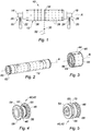
- figure 1 a calibration rotor 10 for a horizontal balancer made according to a prior art.
- the calibration rotor 10 is a monobloc rotor of longitudinal axis A comprising a shaft 12 which is supported at its two opposite ends 14 and 16 by two guide means 18 and 20, respectively.
- the guide means 18 and 20 are cylindrical bearing surfaces 26, 28 of the end of the shaft 12 supported by roller bearings 22, 24 of the balancer.
- the shaft 10 is furthermore capable of being rotated by drive means 30 comprising a belt 32, represented in dotted lines, which is received in an intermediate groove 34 formed in the periphery 36 of the shaft 12.
- the periphery 36 barrel 12 also has fastening points 38 distributed axially and angularly in a regular manner about said axis A, in particular threads, intended to allow the attachment of flyweights (not shown) to the surface of drum 12.
- such a rotor 10 is intended to allow only the balancing of a specific type of balancer, comprising roller bearings 22, 24, and a belt drive 32.
- balancers comprising belt drives, balancers comprising rotatably mounted bearings in half-shell and cantilever drums on the bearings.
- the multiplicity of types of rotor in a balancing workshop comprising balancers of different types therefore implies having a specific calibration rotor 10 for each type of balancer, which is particularly constraining in terms of storage, the rotors calibration being particularly bulky parts.
- the invention provides a modular calibration rotor 10 adaptable to different types of balancers and to provide different overall configurations of barrel.
- the invention proposes a calibration rotor 10 for horizontal balancing, which is configured to be driven by drive means 30 and which comprises in known manner at least one main shaft 12 of longitudinal axis A whose periphery 36 comprises points 38 for fixing balancing weights distributed axially and angularly regularly around said axis A and guide means 18, 20 in rotation of said main shaft, arranged at each end 14, 16 of said main shaft 12.
- each guide means 16, 18 comprises adapters 40, 42 adapted to be fixed to the opposite ends 14, 16 of the barrel.
- the adapter 40, 42 may be of a first type, adapted to a rotation guide of the drum 12 on the rollers 22, 24.
- it may be of a second type, adapted for a rotation guide of the barrel 12 in half-shell 23, that is to say that the adapter is mounted between a flange 25 of the balancer and half a shell 23 which is attached to said flange 25.
- each type of adapter 40, 42 has the same moment of inertia determined, identical from one type to another, and that it can be fixed interchangeably on the barrel .
- the details of the adapters 40, 42 and their attachment will be explained further in the present description.
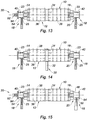
- the shaft 12 may comprise adapters 40, 42 at its two ends 14, 16 for roller guidance 22, 24, as shown in FIGS. Figures 11, 12 , and 19 .
- the drum 12 may comprise adapters 40, 42 at its two ends 14, 16 for a half-shell guide 23 as shown in FIGS. Figures 13, 14 and 20 .
- a mixed guide, comprising an adapter 40 at the end 14 for a roller guide 22 and an adapter 42 at the end 16 for a half-shell guide 23 may also be envisaged as illustrated by FIGS. Figures 17 and 18 .
- a mixed guide comprising an adapter 40 at the end 14 for a half-shell guide 23 and an adapter 42 at the end 16 for a roller guide 22 may also be envisaged as illustrated by FIG. figure 16 .
- the calibration rotor 12 may comprise a tubular secondary shaft 44 having a longitudinal axis B, the periphery of which comprises fixing points 46 of balancing weights distributed axially and angularly in a regular manner about said axis B.
- the secondary shaft 44 is adapted to be fixed cantilevered at one end of at least one adapter 42, so that the longitudinal axes A and B are aligned. The detail of the attachment of the secondary drum 44 will be explained further in the present description.
- the secondary drum 44 advantageously makes it possible to reproduce the configuration of a rotor comprising a portion cantilevered with respect to the bearings 18, 20.
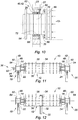
- each adapter of the first type 40, 42 as shown in FIG. figure 4 and to Figures 11, 12 and 19 comprises a one-piece tubular element 46 comprising at least a first end flange 48 adapted to be fixed to a complementary end face 16 of the main drum 12, an intermediate section 50 comprising a raceway 52 configured to cooperate with the rollers 22 , 24 of the balancer, and a second end flange 54.
- the flange 54 is likely to remain free, as shown in FIGS. Figures 11 or 12 , or selectively receive a corresponding flange 56 of the secondary shaft 44 adapted to be cantilevered on said flange 54.
- each adapter 40, 42 is symmetrical with respect to a median axial plane, and its flanges 48, 54 are identical, so that it is not necessary to take into account the orientation of the adapter 40, 42 before assembly.
- Each flange 48, 54 comprises, as illustrated by figure 4 , a series of bores 58 angularly distributed on its periphery, which are intended to be aligned with similar bores 60 carried by a corresponding end face 62 of the drum 12 to allow attachment of the adapter 40, 42 on the drum 12 Similarly, the bores 58 may be aligned with similar bores 64 carried by the corresponding end flange 56 of the secondary shaft 44 to allow attachment of said secondary shaft 44 to the adapter 40, 42.
- each guide adapter 40, 42 of the second type comprises, as illustrated by FIGS. Figures 8 to 10 first and second tubular elements 66, 68 coaxial able to be nested and fixed one into the other.
- these elements 66, 68 respectively comprise a first end flange 48 adapted to be fixed to an end flange 62 complementary to the main drum 12 and a second end flange 54 which is likely to remain free, as represented in Figures 13, 14 , or selectively receive a corresponding flange 56 of said secondary shaft 44.
- the elements 66, 68 also define at their junction an annular receiving groove 70 and axially immobilizing an inner ring 72 of a guide bearing 80 in half shell.
- said bearing 80 comprises an outer ring 82 which is immobilized between the half-shell 23 and the flange 25 of the balancer.
- the first tubular element 66 comprises, at an end opposite its end flange 54, an outer frustoconical bearing surface 84 configured to be received in an internal frustoconical bearing surface 86 of the second tubular element 68, a cylindrical bearing surface 88 adjacent to said bearing frustoconical 84 and intended to define the groove 70, and a tubular section 90 adjacent to the cylindrical bearing surface 88 of greater diameter than said cylindrical seat 88.
- the cylindrical seat 88 thus defines the groove 70 between said tubular section 88 and the second tubular element 68 .
- the first and second coaxial tubular elements 66 and 68 are intended to be fixed to one another by means of screws (not shown) of axis C which axially pass through one of said tubular elements, in this case the second tubular element 68, and which are received in the other tubular element, that is to say the first tubular element 66.
- the tightening of these screws serves to lock the inner ring 72 of the bearing 80 in the groove 70.
- the bearing 80 has also been represented in the half-shell 23 and in the flange 25.
- the bearing 80 comprises two rows of angular contact balls, the outer ring of which is immobilized axially in the half-shell 23 and in the flange 25, on one side by a shoulder 29 and on the other an elastic ring 27, but it will be understood that this configuration is not limiting of the invention.
- each adapter 40, 42 comprises a frustoconical annular centering surface 90 which extends axially from each of its end flanges 50, 54, and which is able to cooperate with a corresponding complementary internal frustoconical surface (not shown) main shaft 12 or secondary shaft 44.
- the frustoconical bearing surface 90 has been shown in the context of the second type of adapter 40, 42, but it will be understood that a similar bearing 90 is provided for the first type of adapter 40, 42.
- Another essential feature of the calibration rotor 10 according to the invention is that it comprises means configured to cooperate with belt drive means 32 or cardan drive means 92 of the balancer.
- the rotor 10 can be rotated in two different ways.
- the means configured to cooperate with the belt drive means 32 comprise at least one groove 34 which is formed at the periphery of the main drum 12, which is arranged in particular in an intermediate portion of said main drum, and which is adapted to receive a drive belt 32 of the balancer.
- This groove 34 is used for driving the rotors 10 in the case of the rotors shown on the figures 12 , 14 , 16 and 18 .
- the means configured to cooperate with cardan drive means 92 of the balancer include the second end flange 54 of the guide adapter 40, which is configured to be configured to be complementary to an collar 92 for coupling cardan 92, and fixing means, in particular by bolting (not shown) which are interposed between said second end flange 54 and said coupling flange 94.
- This configuration was represented at Figures 10-11 , 13 , 15 , 17 , 19 and 20 .
- the rotor 10 can be indifferently driven by the belt 34 or the cardan 92, and that the rotor 10 can be thus adapted to different types of balancers.
- the calibration rotor 10 is capable of being stopped in abutment, in particular in the context of a rotational mounting on the rollers 22, 24.
- the rotor 10 may comprise, like the illustrates the figure 7 , an end stop 96 which is configured to be attached to a free end of at least one of the adapters 40, 42 and / or the secondary shaft 44 to limit the axial displacements of the rotor 10 in operation.
- FIG 7 illustrates an example of such an embodiment.
- An adapter 40, 42 receives at the end of its flange 54 a disk-shaped element 96 which is fixed to the flange by screws 100 and which has a stop pin 102 in the form of a pin which is able to stop the rotor 10 axially bearing on an element (not shown) integral with the frame of the balancer.
- the invention thus makes it possible to propose a calibration rotor 10 capable, on the one hand, of reproducing the configurations of a real rotor, and, on the other hand, capable of being used to calibrate balancers of different types, which makes it possible to to significantly reduce the stock of calibration rotors implemented in a balancing workshop.
Landscapes
- Physics & Mathematics (AREA)
- General Physics & Mathematics (AREA)
- Testing Of Balance (AREA)
- Manufacture Of Motors, Generators (AREA)
Claims (10)
- Kalibrierrotor (10) für eine horizontale Auswuchtvorrichtung, wobei der Rotor konfiguriert ist, um durch Antriebsmittel (30) der Auswuchtvorrichtung angetrieben zu werden und mindestens enthält:- einen Haupthohlkörper (12) mit einer Längsachse A, dessen Peripherie Befestigungspunkte (38) von Auswuchtgewichten enthält, die regelmäßig axial und winklig um die Achse A verteilt sind, und- drehende Führungsmittel (18, 20) des Haupthohlkörpers (12), die an jedem der Enden (14, 16) des Haupthohlkörpers (12) angeordnet sind, dadurch gekennzeichnet, dass der Rotor (10) modular ist und dadurch, dass die Führungsmittel (18, 20) Adapter (40, 42) enthalten, die imstande sind, an den Enden (14, 16) des Hohlkörpers (12) befestigt zu werden, wobei jeder Adapter (40, 42) eines ersten Typs, der an eine Drehführung des Hohlkörpers (12) auf Rollen (22, 24) angepasst ist, oder eines zweiten Typs ist, der an eine halbschalige (23) Drehführung des Hohlkörpers angepasst ist, und jeder Typ von Adapter (40, 42) einen gleichen bestimmten Trägheitsmoment aufweist und auf dem Hohlkörper (12) auswechselbar befestigt werden kann.
- Kalibrierrotor (10) nach dem vorstehenden Anspruch, dadurch gekennzeichnet, dass er einen rohrförmigen sekundären Hohlkörper (44) mit einer Längsachse B enthält, dessen Peripherie Befestigungspunkte (46) von Auswuchtgewichten enthält, die regelmäßig axial und winklig um die Achse B verteilt sind, und der imstande ist, freitragend an einem Ende von mindestens einem Adapter (40, 42) befestigt zu werden, sodass die Längsachsen A und B fluchtend eingerichtet sind.
- Kalibrierrotor (10) nach dem vorstehenden Anspruch, dadurch gekennzeichnet, dass der Adapter (40, 42) des ersten Typs ein einteiliges rohrförmiges Element (46), das mindestens einen ersten Endkragen (48) enthält, der imstande ist, an einer zum Haupthohlkörper (12) komplementären Endseite (16) befestigt zu werden, einen dazwischenliegenden Abschnitt (50), der eine Lagerbahn (52) enthält, die konfiguriert ist, um mit Rollen (22, 24) der Auswuchtvorrichtung zusammenzuwirken, und einen zweiten Endkragen (54), der dazu geeignet ist, selektiv einen entsprechenden Kragen (56) des sekundären Hohlkörpers (44) aufzunehmen, enthält.
- Kalibrierrotor (10) nach Anspruch 2, dadurch gekennzeichnet, dass der Führungsadapter (40, 42) des zweiten Typs ein erstes und zweites koaxiales rohrförmiges Element (66, 68) enthält, die imstande sind, ineinandergefügt und ineinander befestigt zu werden, die jeweils einen ersten Endkragen (48), der imstande ist, an einem komplementären Endkragen (62) des Haupthohlkörpers (12) befestigt zu werden, und einen zweiten Endkragen (54), der dazu geeignet ist, selektiv einen entsprechenden Kragen (56) des sekundären Hohlkörpers (44) aufzunehmen, enthalten, und die an ihrer Verbindung eine axiale ringförmige Aufnahme- und Feststellnut (70) eines inneren Rings (72) eines Lagers (80) einer halbschaligen Führung bestimmen, wobei das Lager (80), einen äußeren Ring (82) enthält, der zwischen einer Halbschale (23) und einem Flansch (25) der Auswuchtvorrichtung festgestellt ist.
- Kalibrierrotor (10) nach dem vorstehenden Anspruch, dadurch gekennzeichnet, dass das erste rohrförmige Element (66) an einem gegenüberliegenden Ende seines Endkragens (54) einen äußeren kegelstumpfartigen Zapfen (84), der konfiguriert ist, um in einem inneren kegelstumpfartigen Zapfen (86) des zweiten rohrförmigen Elements (68) aufgenommen zu werden, einen zylindrischen Zapfen (88), der zum kegelstumpfartigen Zapfen (84) benachbart ist, und einen rohrförmigen Abschnitt (90), der zum zylindrischen Zapfen (88) benachbart ist und einen größeren Durchmesser als der zylindrische Zapfen (88) aufweist, enthält, wobei der zylindrische Zapfen (88) die Nut (70) zwischen dem rohrförmigen Abschnitt (88) und dem zweiten rohrförmigen Element (68) abgrenzt, und dadurch, dass das erste und zweite koaxiale rohrförmige Element (66, 68) durch Schrauben, die eines der rohrförmigen Elemente (68) axial durchqueren, die im anderen rohrförmigen Element (66) aufgenommen werden, und deren Festziehen ermöglicht, den inneren Ring des Lagers (80) in der Nut (70) zu blockieren, aneinander befestigt sind.
- Kalibrierrotor (10) nach einem der Ansprüche 3 bis 5, dadurch gekennzeichnet, dass jeder Adapter einen kegelstumpfartigen ringförmigen Zentrierzapfen (90) enthält, der sich axial von jedem seiner Endkragen (50, 54) aus erstreckt, und der imstande ist, mit einem entsprechenden komplementären inneren kegelstumpfartigen Zapfen des Haupthohlkörpers (12) oder des sekundären Hohlkörpers (44) zusammenzuwirken.
- Kalibrierrotor (10) nach einem der Ansprüche 3 bis 6, dadurch gekennzeichnet, dass er Mittel enthält, die konfiguriert sind, um mit Antriebsmitteln (30) durch einen Riemen (32) oder Antriebsmitteln durch eine Kardanwelle (92) der Auswuchtvorrichtung zusammenzuwirken.
- Kalibrierrotor (10) nach Anspruch 7, dadurch gekennzeichnet, dass die Mittel, die konfiguriert sind, um mit den Antriebsmitteln (30) durch einen Riemen (32) zusammenzuwirken, mindestens eine Nut (34) enthalten, die an der Peripherie des Haupthohlkörpers (12) gebildet ist, die insbesondere in einem dazwischenliegenden Teil des Haupthohlkörpers (12) angeordnet ist, und die imstande ist, einen Antriebsriemen (32) der Auswuchtvorrichtung aufzunehmen.
- Kalibrierrotor (10) nach Anspruch 8, dadurch gekennzeichnet, dass die Mittel, die konfiguriert sind, um mit den Antriebsmitteln (30) durch eine Kardanwelle (92) der Auswuchtvorrichtung zusammenzuwirken, enthalten:- den zweiten Endkragen (54) des Führungsadapters, der konfiguriert ist, um zu einem Kupplungskragen (94) der Kardanwelle (92) komplementär zu sein, und- Fixierungsmittel, insbesondere durch Bolzenverbindung, die zwischen dem zweiten Endkragen (54) und dem Kupplungskragen (92) eingesetzt sind.
- Kalibrierrotor (10) nach einem der Ansprüche 2 bis 9, dadurch gekennzeichnet, dass er eine Anschlagkappe (96) enthält, die konfiguriert ist, um an einem freien Ende von mindestens einem der Adapter (40, 42) und/oder des sekundären Hohlkörpers befestigt zu werden, um die axialen Bewegungen des Rotors (10), der in Betrieb ist, zu begrenzen.
Applications Claiming Priority (2)
| Application Number | Priority Date | Filing Date | Title |
|---|---|---|---|
| FR1556355A FR3038717B1 (fr) | 2015-07-06 | 2015-07-06 | Rotor d'etalonnage modulaire pour equilibreuse horizontale |
| PCT/FR2016/051622 WO2017006016A1 (fr) | 2015-07-06 | 2016-06-29 | Rotor d'etalonnage modulaire pour equilibreuse horizontale |
Publications (2)
| Publication Number | Publication Date |
|---|---|
| EP3320316A1 EP3320316A1 (de) | 2018-05-16 |
| EP3320316B1 true EP3320316B1 (de) | 2019-04-17 |
Family
ID=54260923
Family Applications (1)
| Application Number | Title | Priority Date | Filing Date |
|---|---|---|---|
| EP16744441.3A Active EP3320316B1 (de) | 2015-07-06 | 2016-06-29 | Modularer kalibrierrotor für eine horizontale auswuchtvorrichtung |
Country Status (8)
| Country | Link |
|---|---|
| US (1) | US10197467B2 (de) |
| EP (1) | EP3320316B1 (de) |
| CN (1) | CN107709952B (de) |
| BR (1) | BR112017023156B1 (de) |
| CA (1) | CA2987678C (de) |
| FR (1) | FR3038717B1 (de) |
| RU (1) | RU2712960C2 (de) |
| WO (1) | WO2017006016A1 (de) |
Families Citing this family (1)
| Publication number | Priority date | Publication date | Assignee | Title |
|---|---|---|---|---|
| FR3087686B1 (fr) * | 2018-10-31 | 2020-12-11 | Safran Aircraft Engines | Outillage pour l'equilibrage d'un module de turbomachine comportant un stator en porte a faux |
Family Cites Families (15)
| Publication number | Priority date | Publication date | Assignee | Title |
|---|---|---|---|---|
| US3213689A (en) * | 1960-12-29 | 1965-10-26 | Gen Electric | Method and apparatus for balancing rotors |
| US4750361A (en) * | 1987-01-20 | 1988-06-14 | General Motors Corporation | Universal balancing machine |
| DE3903814A1 (de) * | 1989-02-09 | 1990-08-16 | Hofmann Gmbh & Co Kg Maschinen | Lagerstaender einer auswuchtmaschinenlagerung |
| SU1746481A1 (ru) * | 1990-04-04 | 1992-07-07 | Научно-Исследовательский, Проектно-Конструкторский И Технологический Институт Завода "Сибэлектротяжмаш" | Ротор асинхронного короткозамкнутого двигател |
| US5240358A (en) * | 1990-11-27 | 1993-08-31 | Balance Dynamics Corporation | Method and apparatus for tool balancing |
| DE10116689A1 (de) * | 2001-04-03 | 2002-10-10 | Schenck Rotec Gmbh | Einrichtung zum dynamischen Auswuchten von rotierenden Teilen, insbesondere Kurbelwellen |
| DE10316767A1 (de) * | 2003-04-10 | 2004-10-28 | Schenck Rotec Gmbh | Unwuchtmeßeinrichtung und Verfahren zur Unwuchtmessung |
| ITMI20071908A1 (it) * | 2007-10-04 | 2009-04-05 | Nuovo Pignone Spa | Gruppo di bilanciamento per il rotore di una macchina rotativa a fluido |
| IT1396520B1 (it) | 2009-12-10 | 2012-12-14 | Nuovo Pignone Spa | Accoppiamento per bilanciamento rotore |
| US8886491B2 (en) * | 2010-04-30 | 2014-11-11 | Hunter Engineering Company | Auto-calibrating wheel balancer force transducer |
| ITMI20120257A1 (it) * | 2012-02-21 | 2013-08-22 | Wilic Sarl | Macchina elettrica rotante per aerogeneratore |
| CN103292959A (zh) * | 2012-03-05 | 2013-09-11 | 沈阳黎明航空发动机(集团)有限责任公司 | 发动机转子组件动平衡模拟转子的参数分析及检测方法 |
| CN203899699U (zh) * | 2013-12-30 | 2014-10-29 | 上海麦冠实业有限公司 | 一种汽车轮胎撕碎机的转子 |
| CN103994856B (zh) * | 2014-05-29 | 2016-08-24 | 北京航天动力研究所 | 一种高速转子动特性试验台校准用标准转子 |
| US9816899B2 (en) * | 2015-07-24 | 2017-11-14 | Snap-On Equipment Srl A Unico Socio | Communication system for a tyre service machine and measuring unit for being used with such communication system |
-
2015
- 2015-07-06 FR FR1556355A patent/FR3038717B1/fr active Active
-
2016
- 2016-06-29 US US15/578,204 patent/US10197467B2/en active Active
- 2016-06-29 CA CA2987678A patent/CA2987678C/fr active Active
- 2016-06-29 BR BR112017023156-5A patent/BR112017023156B1/pt active IP Right Grant
- 2016-06-29 RU RU2017141564A patent/RU2712960C2/ru active
- 2016-06-29 CN CN201680031766.3A patent/CN107709952B/zh active Active
- 2016-06-29 EP EP16744441.3A patent/EP3320316B1/de active Active
- 2016-06-29 WO PCT/FR2016/051622 patent/WO2017006016A1/fr not_active Ceased
Non-Patent Citations (1)
| Title |
|---|
| None * |
Also Published As
| Publication number | Publication date |
|---|---|
| RU2017141564A (ru) | 2019-08-06 |
| US10197467B2 (en) | 2019-02-05 |
| CN107709952B (zh) | 2019-04-02 |
| EP3320316A1 (de) | 2018-05-16 |
| CN107709952A (zh) | 2018-02-16 |
| FR3038717A1 (fr) | 2017-01-13 |
| BR112017023156B1 (pt) | 2020-12-29 |
| BR112017023156A2 (pt) | 2018-07-24 |
| WO2017006016A1 (fr) | 2017-01-12 |
| CA2987678C (fr) | 2023-08-01 |
| FR3038717B1 (fr) | 2017-07-21 |
| RU2017141564A3 (de) | 2019-11-18 |
| CA2987678A1 (fr) | 2017-01-12 |
| RU2712960C2 (ru) | 2020-02-03 |
| US20180149544A1 (en) | 2018-05-31 |
Similar Documents
| Publication | Publication Date | Title |
|---|---|---|
| EP2627870B1 (de) | Anschlussmodul zwischen einer antriebswelle eines motorlüfters und einem wälzlager | |
| EP2893158B1 (de) | Turbinenmotor mit einer vorrichtung zum messen der geschwindigkeit und des drehmoments einer welle des turbinenmotors und verfahren zur überwachung der welle | |
| FR2825765A1 (fr) | Roulement a deux rangees dissymetriques de billes a contact oblique, et montage de pignons en porte-a-faux sur un tel roulement | |
| FR2560654A1 (fr) | Dispositif d'amortissement pour absorber ou compenser des chocs angulaires | |
| FR2972963A1 (fr) | Element de suspension pour machine automotrice | |
| EP2935939B1 (de) | Vorrichtung zur absorption von vibrationen | |
| FR2986840A1 (fr) | Ensemble de roulements et machine tournante correspondante | |
| FR2976615A1 (fr) | Structure de rotor comprenant un dispositif de tension hydraulique interne | |
| EP2935938B1 (de) | Schwingungsdämpfende vorrichtung | |
| EP3063418B1 (de) | Verbindungsanordnung mit einem haltering für eine welle verfahren zur montage solch einer verbindungsanordnung | |
| EP0153887B1 (de) | Auswuchteinrichtung und Ausstattung für den Läufer eines Gasturbinentriebwerks und Verfahren zur Anwendung | |
| CA2987678C (fr) | Rotor d'etalonnage modulaire pour equilibreuse horizontale | |
| FR2949138A1 (fr) | Turbomachine comportant des moyens d'anti-rotation d'un ecrou de palier | |
| WO2016113494A1 (fr) | Procédé de fabrication d'un réducteur d'hélice | |
| WO2015075146A1 (fr) | Système de transfert de puissance entre trois composants de puissance | |
| FR2949858A1 (fr) | Dispositif et procede d'equilibrage | |
| FR2929358A1 (fr) | Palier de guidage d'arbre dans une turbomachine | |
| FR2858294A1 (fr) | Roue d'inertie pour vehicule | |
| EP0119123B1 (de) | Auswuchtvorrichtung, insbesondere für Kraftfahrzeugräder | |
| WO2010026319A1 (fr) | Procede et dispositif de mesure de balourd de vilebrequin | |
| FR3122227A1 (fr) | Doublon de roulements amélioré | |
| FR2988789A1 (fr) | Dispositif de calage axial d'un roulement soumis a un debattement angulaire | |
| FR3000161A1 (fr) | Dispositif d'absorption de vibrations destine a la transmission d'un vehicule automobile | |
| FR3000160A1 (fr) | Dispositif d'absorption de vibrations destine a la transmission d'un vehicule automobile | |
| FR2918453A1 (fr) | Outillage de fixation d'un arbre de transmission et banc d'equilibrage comportant un tel outillage |
Legal Events
| Date | Code | Title | Description |
|---|---|---|---|
| STAA | Information on the status of an ep patent application or granted ep patent |
Free format text: STATUS: THE INTERNATIONAL PUBLICATION HAS BEEN MADE |
|
| PUAI | Public reference made under article 153(3) epc to a published international application that has entered the european phase |
Free format text: ORIGINAL CODE: 0009012 |
|
| STAA | Information on the status of an ep patent application or granted ep patent |
Free format text: STATUS: REQUEST FOR EXAMINATION WAS MADE |
|
| 17P | Request for examination filed |
Effective date: 20171219 |
|
| AK | Designated contracting states |
Kind code of ref document: A1 Designated state(s): AL AT BE BG CH CY CZ DE DK EE ES FI FR GB GR HR HU IE IS IT LI LT LU LV MC MK MT NL NO PL PT RO RS SE SI SK SM TR |
|
| AX | Request for extension of the european patent |
Extension state: BA ME |
|
| DAV | Request for validation of the european patent (deleted) | ||
| DAX | Request for extension of the european patent (deleted) | ||
| GRAP | Despatch of communication of intention to grant a patent |
Free format text: ORIGINAL CODE: EPIDOSNIGR1 |
|
| STAA | Information on the status of an ep patent application or granted ep patent |
Free format text: STATUS: GRANT OF PATENT IS INTENDED |
|
| INTG | Intention to grant announced |
Effective date: 20181031 |
|
| GRAS | Grant fee paid |
Free format text: ORIGINAL CODE: EPIDOSNIGR3 |
|
| GRAA | (expected) grant |
Free format text: ORIGINAL CODE: 0009210 |
|
| STAA | Information on the status of an ep patent application or granted ep patent |
Free format text: STATUS: THE PATENT HAS BEEN GRANTED |
|
| AK | Designated contracting states |
Kind code of ref document: B1 Designated state(s): AL AT BE BG CH CY CZ DE DK EE ES FI FR GB GR HR HU IE IS IT LI LT LU LV MC MK MT NL NO PL PT RO RS SE SI SK SM TR |
|
| REG | Reference to a national code |
Ref country code: GB Ref legal event code: FG4D Free format text: NOT ENGLISH |
|
| REG | Reference to a national code |
Ref country code: CH Ref legal event code: EP |
|
| REG | Reference to a national code |
Ref country code: DE Ref legal event code: R096 Ref document number: 602016012633 Country of ref document: DE |
|
| REG | Reference to a national code |
Ref country code: AT Ref legal event code: REF Ref document number: 1122082 Country of ref document: AT Kind code of ref document: T Effective date: 20190515 Ref country code: IE Ref legal event code: FG4D Free format text: LANGUAGE OF EP DOCUMENT: FRENCH |
|
| REG | Reference to a national code |
Ref country code: SE Ref legal event code: TRGR |
|
| REG | Reference to a national code |
Ref country code: NL Ref legal event code: MP Effective date: 20190417 |
|
| REG | Reference to a national code |
Ref country code: LT Ref legal event code: MG4D |
|
| PG25 | Lapsed in a contracting state [announced via postgrant information from national office to epo] |
Ref country code: NL Free format text: LAPSE BECAUSE OF FAILURE TO SUBMIT A TRANSLATION OF THE DESCRIPTION OR TO PAY THE FEE WITHIN THE PRESCRIBED TIME-LIMIT Effective date: 20190417 |
|
| PG25 | Lapsed in a contracting state [announced via postgrant information from national office to epo] |
Ref country code: NO Free format text: LAPSE BECAUSE OF FAILURE TO SUBMIT A TRANSLATION OF THE DESCRIPTION OR TO PAY THE FEE WITHIN THE PRESCRIBED TIME-LIMIT Effective date: 20190717 Ref country code: FI Free format text: LAPSE BECAUSE OF FAILURE TO SUBMIT A TRANSLATION OF THE DESCRIPTION OR TO PAY THE FEE WITHIN THE PRESCRIBED TIME-LIMIT Effective date: 20190417 Ref country code: HR Free format text: LAPSE BECAUSE OF FAILURE TO SUBMIT A TRANSLATION OF THE DESCRIPTION OR TO PAY THE FEE WITHIN THE PRESCRIBED TIME-LIMIT Effective date: 20190417 Ref country code: PT Free format text: LAPSE BECAUSE OF FAILURE TO SUBMIT A TRANSLATION OF THE DESCRIPTION OR TO PAY THE FEE WITHIN THE PRESCRIBED TIME-LIMIT Effective date: 20190817 Ref country code: ES Free format text: LAPSE BECAUSE OF FAILURE TO SUBMIT A TRANSLATION OF THE DESCRIPTION OR TO PAY THE FEE WITHIN THE PRESCRIBED TIME-LIMIT Effective date: 20190417 Ref country code: AL Free format text: LAPSE BECAUSE OF FAILURE TO SUBMIT A TRANSLATION OF THE DESCRIPTION OR TO PAY THE FEE WITHIN THE PRESCRIBED TIME-LIMIT Effective date: 20190417 Ref country code: LT Free format text: LAPSE BECAUSE OF FAILURE TO SUBMIT A TRANSLATION OF THE DESCRIPTION OR TO PAY THE FEE WITHIN THE PRESCRIBED TIME-LIMIT Effective date: 20190417 |
|
| PG25 | Lapsed in a contracting state [announced via postgrant information from national office to epo] |
Ref country code: BG Free format text: LAPSE BECAUSE OF FAILURE TO SUBMIT A TRANSLATION OF THE DESCRIPTION OR TO PAY THE FEE WITHIN THE PRESCRIBED TIME-LIMIT Effective date: 20190717 Ref country code: PL Free format text: LAPSE BECAUSE OF FAILURE TO SUBMIT A TRANSLATION OF THE DESCRIPTION OR TO PAY THE FEE WITHIN THE PRESCRIBED TIME-LIMIT Effective date: 20190417 Ref country code: RS Free format text: LAPSE BECAUSE OF FAILURE TO SUBMIT A TRANSLATION OF THE DESCRIPTION OR TO PAY THE FEE WITHIN THE PRESCRIBED TIME-LIMIT Effective date: 20190417 Ref country code: LV Free format text: LAPSE BECAUSE OF FAILURE TO SUBMIT A TRANSLATION OF THE DESCRIPTION OR TO PAY THE FEE WITHIN THE PRESCRIBED TIME-LIMIT Effective date: 20190417 Ref country code: GR Free format text: LAPSE BECAUSE OF FAILURE TO SUBMIT A TRANSLATION OF THE DESCRIPTION OR TO PAY THE FEE WITHIN THE PRESCRIBED TIME-LIMIT Effective date: 20190718 |
|
| REG | Reference to a national code |
Ref country code: AT Ref legal event code: MK05 Ref document number: 1122082 Country of ref document: AT Kind code of ref document: T Effective date: 20190417 |
|
| PG25 | Lapsed in a contracting state [announced via postgrant information from national office to epo] |
Ref country code: IS Free format text: LAPSE BECAUSE OF FAILURE TO SUBMIT A TRANSLATION OF THE DESCRIPTION OR TO PAY THE FEE WITHIN THE PRESCRIBED TIME-LIMIT Effective date: 20190817 |
|
| REG | Reference to a national code |
Ref country code: DE Ref legal event code: R097 Ref document number: 602016012633 Country of ref document: DE |
|
| PG25 | Lapsed in a contracting state [announced via postgrant information from national office to epo] |
Ref country code: SK Free format text: LAPSE BECAUSE OF FAILURE TO SUBMIT A TRANSLATION OF THE DESCRIPTION OR TO PAY THE FEE WITHIN THE PRESCRIBED TIME-LIMIT Effective date: 20190417 Ref country code: RO Free format text: LAPSE BECAUSE OF FAILURE TO SUBMIT A TRANSLATION OF THE DESCRIPTION OR TO PAY THE FEE WITHIN THE PRESCRIBED TIME-LIMIT Effective date: 20190417 Ref country code: EE Free format text: LAPSE BECAUSE OF FAILURE TO SUBMIT A TRANSLATION OF THE DESCRIPTION OR TO PAY THE FEE WITHIN THE PRESCRIBED TIME-LIMIT Effective date: 20190417 Ref country code: DK Free format text: LAPSE BECAUSE OF FAILURE TO SUBMIT A TRANSLATION OF THE DESCRIPTION OR TO PAY THE FEE WITHIN THE PRESCRIBED TIME-LIMIT Effective date: 20190417 Ref country code: AT Free format text: LAPSE BECAUSE OF FAILURE TO SUBMIT A TRANSLATION OF THE DESCRIPTION OR TO PAY THE FEE WITHIN THE PRESCRIBED TIME-LIMIT Effective date: 20190417 Ref country code: MC Free format text: LAPSE BECAUSE OF FAILURE TO SUBMIT A TRANSLATION OF THE DESCRIPTION OR TO PAY THE FEE WITHIN THE PRESCRIBED TIME-LIMIT Effective date: 20190417 Ref country code: CZ Free format text: LAPSE BECAUSE OF FAILURE TO SUBMIT A TRANSLATION OF THE DESCRIPTION OR TO PAY THE FEE WITHIN THE PRESCRIBED TIME-LIMIT Effective date: 20190417 |
|
| REG | Reference to a national code |
Ref country code: CH Ref legal event code: PL |
|
| PLBE | No opposition filed within time limit |
Free format text: ORIGINAL CODE: 0009261 |
|
| STAA | Information on the status of an ep patent application or granted ep patent |
Free format text: STATUS: NO OPPOSITION FILED WITHIN TIME LIMIT |
|
| PG25 | Lapsed in a contracting state [announced via postgrant information from national office to epo] |
Ref country code: SM Free format text: LAPSE BECAUSE OF FAILURE TO SUBMIT A TRANSLATION OF THE DESCRIPTION OR TO PAY THE FEE WITHIN THE PRESCRIBED TIME-LIMIT Effective date: 20190417 |
|
| 26N | No opposition filed |
Effective date: 20200120 |
|
| REG | Reference to a national code |
Ref country code: BE Ref legal event code: MM Effective date: 20190630 |
|
| PG25 | Lapsed in a contracting state [announced via postgrant information from national office to epo] |
Ref country code: TR Free format text: LAPSE BECAUSE OF FAILURE TO SUBMIT A TRANSLATION OF THE DESCRIPTION OR TO PAY THE FEE WITHIN THE PRESCRIBED TIME-LIMIT Effective date: 20190417 |
|
| PG25 | Lapsed in a contracting state [announced via postgrant information from national office to epo] |
Ref country code: IE Free format text: LAPSE BECAUSE OF NON-PAYMENT OF DUE FEES Effective date: 20190629 |
|
| PG25 | Lapsed in a contracting state [announced via postgrant information from national office to epo] |
Ref country code: LI Free format text: LAPSE BECAUSE OF NON-PAYMENT OF DUE FEES Effective date: 20190630 Ref country code: CH Free format text: LAPSE BECAUSE OF NON-PAYMENT OF DUE FEES Effective date: 20190630 Ref country code: SI Free format text: LAPSE BECAUSE OF FAILURE TO SUBMIT A TRANSLATION OF THE DESCRIPTION OR TO PAY THE FEE WITHIN THE PRESCRIBED TIME-LIMIT Effective date: 20190417 Ref country code: LU Free format text: LAPSE BECAUSE OF NON-PAYMENT OF DUE FEES Effective date: 20190629 Ref country code: BE Free format text: LAPSE BECAUSE OF NON-PAYMENT OF DUE FEES Effective date: 20190630 |
|
| PG25 | Lapsed in a contracting state [announced via postgrant information from national office to epo] |
Ref country code: CY Free format text: LAPSE BECAUSE OF FAILURE TO SUBMIT A TRANSLATION OF THE DESCRIPTION OR TO PAY THE FEE WITHIN THE PRESCRIBED TIME-LIMIT Effective date: 20190417 |
|
| PG25 | Lapsed in a contracting state [announced via postgrant information from national office to epo] |
Ref country code: MT Free format text: LAPSE BECAUSE OF FAILURE TO SUBMIT A TRANSLATION OF THE DESCRIPTION OR TO PAY THE FEE WITHIN THE PRESCRIBED TIME-LIMIT Effective date: 20190417 Ref country code: HU Free format text: LAPSE BECAUSE OF FAILURE TO SUBMIT A TRANSLATION OF THE DESCRIPTION OR TO PAY THE FEE WITHIN THE PRESCRIBED TIME-LIMIT; INVALID AB INITIO Effective date: 20160629 |
|
| PG25 | Lapsed in a contracting state [announced via postgrant information from national office to epo] |
Ref country code: MK Free format text: LAPSE BECAUSE OF FAILURE TO SUBMIT A TRANSLATION OF THE DESCRIPTION OR TO PAY THE FEE WITHIN THE PRESCRIBED TIME-LIMIT Effective date: 20190417 |
|
| PGFP | Annual fee paid to national office [announced via postgrant information from national office to epo] |
Ref country code: DE Payment date: 20250618 Year of fee payment: 10 |
|
| PGFP | Annual fee paid to national office [announced via postgrant information from national office to epo] |
Ref country code: GB Payment date: 20250625 Year of fee payment: 10 |
|
| PGFP | Annual fee paid to national office [announced via postgrant information from national office to epo] |
Ref country code: FR Payment date: 20250620 Year of fee payment: 10 |
|
| PGFP | Annual fee paid to national office [announced via postgrant information from national office to epo] |
Ref country code: SE Payment date: 20250618 Year of fee payment: 10 |
|
| PGFP | Annual fee paid to national office [announced via postgrant information from national office to epo] |
Ref country code: IT Payment date: 20250630 Year of fee payment: 10 |