EP3320582B1 - Borne de connexion - Google Patents
Borne de connexion Download PDFInfo
- Publication number
- EP3320582B1 EP3320582B1 EP16734708.7A EP16734708A EP3320582B1 EP 3320582 B1 EP3320582 B1 EP 3320582B1 EP 16734708 A EP16734708 A EP 16734708A EP 3320582 B1 EP3320582 B1 EP 3320582B1
- Authority
- EP
- European Patent Office
- Prior art keywords
- busbar
- leg
- connection terminal
- current bar
- housing
- Prior art date
- Legal status (The legal status is an assumption and is not a legal conclusion. Google has not performed a legal analysis and makes no representation as to the accuracy of the status listed.)
- Active
Links
Images


Classifications
-
- H—ELECTRICITY
- H01—ELECTRIC ELEMENTS
- H01R—ELECTRICALLY-CONDUCTIVE CONNECTIONS; STRUCTURAL ASSOCIATIONS OF A PLURALITY OF MUTUALLY-INSULATED ELECTRICAL CONNECTING ELEMENTS; COUPLING DEVICES; CURRENT COLLECTORS
- H01R9/00—Structural associations of a plurality of mutually-insulated electrical connecting elements, e.g. terminal strips or terminal blocks; Terminals or binding posts mounted upon a base or in a case; Bases therefor
- H01R9/22—Bases, e.g. strip, block, panel
- H01R9/24—Terminal blocks
- H01R9/26—Clip-on terminal blocks for side-by-side rail- or strip-mounting
- H01R9/2675—Electrical interconnections between two blocks, e.g. by means of busbars
-
- H—ELECTRICITY
- H01—ELECTRIC ELEMENTS
- H01R—ELECTRICALLY-CONDUCTIVE CONNECTIONS; STRUCTURAL ASSOCIATIONS OF A PLURALITY OF MUTUALLY-INSULATED ELECTRICAL CONNECTING ELEMENTS; COUPLING DEVICES; CURRENT COLLECTORS
- H01R25/00—Coupling parts adapted for simultaneous co-operation with two or more identical counterparts, e.g. for distributing energy to two or more circuits
- H01R25/14—Rails or bus-bars constructed so that the counterparts can be connected thereto at any point along their length
-
- H—ELECTRICITY
- H01—ELECTRIC ELEMENTS
- H01R—ELECTRICALLY-CONDUCTIVE CONNECTIONS; STRUCTURAL ASSOCIATIONS OF A PLURALITY OF MUTUALLY-INSULATED ELECTRICAL CONNECTING ELEMENTS; COUPLING DEVICES; CURRENT COLLECTORS
- H01R4/00—Electrically-conductive connections between two or more conductive members in direct contact, i.e. touching one another; Means for effecting or maintaining such contact; Electrically-conductive connections having two or more spaced connecting locations for conductors and using contact members penetrating insulation
- H01R4/28—Clamped connections, spring connections
- H01R4/48—Clamped connections, spring connections utilising a spring, clip, or other resilient member
- H01R4/4809—Clamped connections, spring connections utilising a spring, clip, or other resilient member using a leaf spring to bias the conductor toward the busbar
- H01R4/48185—Clamped connections, spring connections utilising a spring, clip, or other resilient member using a leaf spring to bias the conductor toward the busbar adapted for axial insertion of a wire end
- H01R4/4819—Clamped connections, spring connections utilising a spring, clip, or other resilient member using a leaf spring to bias the conductor toward the busbar adapted for axial insertion of a wire end the spring shape allowing insertion of the conductor end when the spring is unbiased
- H01R4/4821—Single-blade spring
-
- H—ELECTRICITY
- H01—ELECTRIC ELEMENTS
- H01R—ELECTRICALLY-CONDUCTIVE CONNECTIONS; STRUCTURAL ASSOCIATIONS OF A PLURALITY OF MUTUALLY-INSULATED ELECTRICAL CONNECTING ELEMENTS; COUPLING DEVICES; CURRENT COLLECTORS
- H01R4/00—Electrically-conductive connections between two or more conductive members in direct contact, i.e. touching one another; Means for effecting or maintaining such contact; Electrically-conductive connections having two or more spaced connecting locations for conductors and using contact members penetrating insulation
- H01R4/28—Clamped connections, spring connections
- H01R4/48—Clamped connections, spring connections utilising a spring, clip, or other resilient member
- H01R4/4809—Clamped connections, spring connections utilising a spring, clip, or other resilient member using a leaf spring to bias the conductor toward the busbar
- H01R4/4828—Spring-activating arrangements mounted on or integrally formed with the spring housing
- H01R4/4833—Sliding arrangements, e.g. sliding button
-
- H—ELECTRICITY
- H01—ELECTRIC ELEMENTS
- H01R—ELECTRICALLY-CONDUCTIVE CONNECTIONS; STRUCTURAL ASSOCIATIONS OF A PLURALITY OF MUTUALLY-INSULATED ELECTRICAL CONNECTING ELEMENTS; COUPLING DEVICES; CURRENT COLLECTORS
- H01R4/00—Electrically-conductive connections between two or more conductive members in direct contact, i.e. touching one another; Means for effecting or maintaining such contact; Electrically-conductive connections having two or more spaced connecting locations for conductors and using contact members penetrating insulation
- H01R4/28—Clamped connections, spring connections
- H01R4/48—Clamped connections, spring connections utilising a spring, clip, or other resilient member
- H01R4/4809—Clamped connections, spring connections utilising a spring, clip, or other resilient member using a leaf spring to bias the conductor toward the busbar
- H01R4/4846—Busbar details
Definitions
- the invention relates to a connection terminal for connecting an electrical conductor to a busbar.
- Connection terminals are known in a large number of embodiments.
- Connection terminals can be designed, for example, for connecting a conductor to a printed circuit board as a so-called print terminal or - as in the context of the present patent application - for connecting an electrical conductor to a busbar.
- shield clamps have been known for many years, with which the cable shield of a generally multi-core cable can be connected to a busbar.
- Such shield clamps are from the Catalog "Terminal Blocks CLIPLINE 1 2011", pages 546 - 548 from Phoenix Contact GmbH & Co. KG known.
- the known shield clamps have an approximately U-shaped metallic connection body, with slots being formed in the two legs of the connection body with which the shield clamp can be plugged onto a busbar with a predetermined thickness.
- a knurled screw is provided, via which a large, resilient pressure piece can be adjusted in height so that the cable to be connected can be clamped between the pressure piece and the busbar.
- connection terminals are only suitable for connecting the cable shield of a cable to a busbar that is connected to reference potential.
- the busbar is connected to a support rail via support blocks, on which several terminal blocks are then arranged, to which the individual wires of the multi-core cable are connected.
- the DE 201 19 510 U1 discloses a collective terminal for connecting a plurality of electrical conductors to a busbar, the connecting terminal has a plurality of spring elements as conductor connection elements and a group busbar.
- steel retaining springs are provided which clamp the busbar to the busbar.
- a rear catch is provided on the housing of the collective connection, which engages behind the busbar.
- the DE 197 53 076 C1 discloses an electrical connection terminal for arrangement on a printed circuit board, to which at least one electrical conductor can be connected.
- the known connection terminal has a housing in which a conductor connection element and a current bar are arranged.
- a conductor insertion opening and a receptacle for a circuit board are formed in the housing.
- One end of the current bar protrudes from the housing, so that this end, which serves as a contact leg, contacts a contact surface on a printed circuit board which is plugged into the receptacle.
- the connection terminal can be arranged on a circuit board with SMD soldering surfaces without through-holes.
- the present invention is based on the object of specifying a connection terminal for connecting an electrical conductor to a busbar, in which connection to the busbar is as simple as possible.
- a secure electrical connection between the conductor to be connected and the busbar should also be ensured if the busbars have certain tolerances in terms of their thickness.
- connection terminal for connecting an electrical conductor to a busbar with the features of claim 1.
- the connection terminal has a housing in which a conductor connection element and a current bar are arranged.
- a conductor insertion opening for inserting the electrical conductor to be connected and a busbar receptacle for receiving the busbar are formed in the housing.
- a conductor connected by means of the conductor connection element is then connected in an electrically conductive manner via the current bar to the busbar arranged in the busbar receptacle.
- the current bar is slidably mounted in the housing, and that a spring element is arranged in the housing in such a way that the spring element applies a force to the current bar in the direction of the busbar receptacle.
- the spring element ensures that there is always a sufficient and largely constant contact force between the current bar and a busbar inserted in the busbar receptacle, so that good electrical contact between the current bar and the busbar is ensured. Due to the displaceable arrangement of the current bar in the housing in conjunction with the force acting on the current bar through the spring element in the direction of the busbar receptacle, tolerances in the thickness of the busbar used can be reliably compensated for.
- the spring element is designed as an essentially U-shaped or V-shaped leg spring which has two legs.
- the first leg is supported as a kind of contact leg on an abutment in the housing, while the second leg is in contact with the current bar.
- the contact between the second leg of the leg spring and the current bar can be implemented in that the second leg of the leg spring engages with its free end in a corresponding recess in the current bar.
- the second leg is positively connected to the current bar, so that the position of the free end of the second leg relative to the current bar does not change.
- the second leg of the leg spring is simply on the end of the current bar facing away from the busbar receptacle or the end of the current bar presses against the second leg of the leg spring.
- the formation of a recess in the current bar can be dispensed with here.
- the leg spring is clamped with its two legs between the abutment in the housing and the current bar, and the leg spring can also be secured in its position by corresponding ribs or retaining domes in the housing.
- connection element such as screw connections or tension springs
- a leg spring is particularly preferably used as the conductor connection element, which has a contact leg and a clamping leg, the clamping leg together with the current bar forming a spring-loaded clamping point for the stripped conductor to be connected.
- an actuating opening for inserting the tip of a tool for example a screwdriver, can be formed in the housing in addition to the conductor insertion opening.
- an actuation lever is arranged displaceably in the housing.
- the actuating pusher can be moved from a first position in which the clamping leg of the leg spring is not deflected into a second position in which the clamping leg is deflected by the tip of the operating pusher, so that a connected electrical conductor out of the clamping point and thus also can be pulled out of the conductor entry opening.
- connection terminal preferably has a clamping lever which is rotatably mounted in the housing on the side of the busbar receptacle opposite the current bar.
- the clamping lever has at least one clamping nose which protrudes into the busbar receptacle and, in the case of a busbar arranged in the busbar receptacle, rests against the busbar on the side of the busbar facing away from the current bar.
- a busbar arranged in the busbar receptacle is pressed against the current bar by the clamping lever and clamped between the current bar and the clamping lug of the clamping lever, so that the busbar is also held in the busbar receptacle at the same time.
- the clamping lever preferably also has an actuating projection, the free end of which is at a greater distance from the pivot point of the clamping lever than the clamping lug, so that the actuating projection - when the busbar is not inserted - protrudes further into the busbar receptacle than the clamping lug.
- the clamping lever When the connection terminal with the busbar receptacle is plugged onto a busbar or when the busbar is inserted into the busbar receptacle of the connection terminal, the clamping lever is thereby automatically pivoted until the busbar is completely in the busbar receptacle is arranged, and the busbar is clamped between the clamping lug and the current bar, which is pressed against the busbar by the force of the spring element.
- an additional fixation can be provided.
- the fixation is realized according to a preferred embodiment of the invention by a further spring element which has at least one leg and is arranged in the housing such that the free end of the leg protrudes into the busbar receptacle when no busbar is arranged in the busbar receptacle. If a busbar is inserted into the receptacle, the spring element is deflected against its spring force, the free end of the leg of the spring element resting against the busbar at an acute angle. A busbar introduced into the busbar receptacle is thus secured by self-locking against inadvertent removal of the connection terminal from the busbar in the opposite direction to the attachment direction.
- the use of a spring element for fixing the busbar has the advantage that, on the one hand, the spring element does not noticeably hinder the introduction of the busbar into the busbar receptacle, and on the other hand, the fixation is effective after the busbar has been inserted without the user being actuated requirement.
- the further spring element is preferably also designed as a leg spring which has two legs, the second leg, which is not in contact with the busbar, being supported as a bearing leg on an abutment in the housing.
- connection terminal with a further leg spring serving to fix the busbar
- the connection terminal has an unlocking element according to a further advantageous embodiment.
- the unlocking element is movable on the or arranged in the housing so that it can be brought from a basic position into an unlocked position. In the unlocked position, the leg of the spring element that faces the busbar and fixes the busbar in its position is deflected by the unlocking element so that the free end of the leg no longer rests on the side of the busbar.
- the connection terminal can then be lifted off the busbar counter to the plug-on direction or the busbar can be pulled out of the busbar receptacle counter to the plug-in direction.
- the unlocking element - similar to the actuating lever - could be arranged displaceably in the housing.
- the unlocking element is designed as a lever which is pivotably attached to the housing via a hinge, the unlocking element having a gripping surface for actuation with a finger.
- the actuation of the unlocking element can be carried out very easily by a fitter, for example by simply pressing with a finger on the gripping surface of the lever when lifting the connection terminal from the busbar, whereby the lever is pivoted so that the leg of the spring element is deflected and thereby the Lock is released.
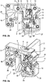
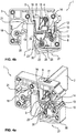
- connection terminal 1 for connecting an electrical conductor - not shown here - to a busbar 2. While in FIG Fig. 1 the connection terminal 1 is shown without busbar 2, show the Fig. 2 , 3 and 4th the connection terminal 1 with two busbars 2 of different thicknesses, namely one with a first, thinner busbar 2 ( Fig. 2 and 4th ) and once with a second, thicker busbar 2 ( Fig. 3 ). In Fig. 4 is the terminal 1 with the thinner busbar 2 according to Fig. 2 shown, whereby in contrast to Fig. 2 the fixing formed between the connection terminal 1 and the busbar 2 is released, so that the connection terminal 1 can be lifted off the busbar 2 in the opposite direction to the attachment direction A.
- the connection terminal 1 has a housing 3 in which a conductor connection element 4 in the form of a leg spring and an L-shaped current bar 5 are arranged. To insert a conductor to be connected into the terminal point, a conductor insertion opening 6 is formed in the housing 3.
- the housing 3, which is usually made of plastic also has a busbar receptacle 7, which is open on one side, so that the connection terminal 1 can be plugged or placed on a busbar 2 with the busbar receptacle 7, which may have already been installed, in the plug-in direction A. If the connection terminal 1 has already been installed, there is the possibility of inserting a busbar 2 into the busbar receptacle 7 from the direction opposite to the direction of attachment A.
- the current bar 5 is mounted in the housing 3 so as to be displaceable - perpendicular to the attachment direction A.
- the current bar 5 is pressed by a spring element 8 with a force in the direction of the busbar receptacle 7 or in the direction of a busbar 2 arranged in the busbar receptacle 7, so that it is ensured that there is always a sufficient contact force and thus a good electrical contact between the current bar 5 and the busbar 2 consists.
- the spring element 8, which presses the current bar 5 against the busbar 2 is designed as a leg spring which has two legs 10, 11.
- the first leg 10 serves as a contact leg which is supported on an abutment 12 in the housing 3, while the second leg 11 is in contact with the current bar 5.
- the second leg 11 rests against the end 13 of the current bar 5 facing away from the busbar receptacle 7.
- the spring element 8 is thus clamped with its two legs 10, 11 between the abutment 12 in the housing 3 and the end 13 of the current bar 5.
- the assembly of the current bar 5 and spring element 8 in the housing 3 is very simple, since the current bar 5 and the spring element 8 can be inserted individually into the housing 3.
- the conductor connection element 4 is also designed as a leg spring which has two legs, namely a contact leg 14 and a clamping leg 15.
- a stripped electrical conductor inserted through the conductor insertion opening 6 into the housing 3 is then through the clamping leg 15 is pressed against the leg 16 of the current bar 5, which is also in contact with an inserted busbar 2.
- the clamping leg 15 thus forms, together with the leg 16 of the current bar 5, a spring force clamping point for the conductor to be connected.
- the connecting terminal 1 has an actuating lever 17 which is arranged displaceably in the housing 3 and which can be displaced from a first position shown in the figures into a second position within the housing 3. While the clamping leg 15 is not deflected in the first position of the actuating printer 17, the clamping leg 15 is deflected in the second position of the actuating lever 17 to such an extent that a connected conductor is no longer clamped in the clamping point and thus out of the connection terminal 1 through the conductor entry opening 6 can be pulled out.
- a clamping lever 18 is rotatably mounted in the housing 3, by means of which the busbar 2 is held in the busbar receptacle 7 and, in particular, is pressed in the direction of the current bar 5.
- the clamping lever 18 thus serves in particular for the correct positioning of the busbar 2 on the current bar 5 or its first leg 16.
- the clamping lever 18 has two clamping lugs 19, 20 protruding into the busbar receptacle 7 and an actuating projection 21.
- the first clamping lug 19 Fig. 2 and 4th
- the second clamping lug 20 Fig. 3
- the free end of the actuating projection 21 is at a greater distance from the pivot point of the clamping lever 18 than the clamping lug 19 and - a significantly greater distance - than the clamping lug 20.
- the actuating projection 21 thus protrudes farthest into the busbar receptacle 7 when the busbar receptacle 7 is free into it, so that when the housing 3 is plugged onto a busbar 2, the busbar 2 first abuts the actuating projection 21 and thereby pivots the clamping lever 18 counterclockwise until the housing 3 is completely placed on the busbar 2, so that according to FIG Fig. 2 the first clamping lug 19 or in the embodiment according to Fig. 3 the second clamping lug 20 rests against the busbar 2 and thereby presses it against the current bar 5.
- a further spring element 22, also designed as a leg spring, is arranged in the housing 3 in addition to the spring element 8 pressing the current bar 5 against a busbar 2.
- a total of three leg springs are thus arranged in the housing 3, all of which perform three different functions.
- the spring element 22 is arranged in the housing 3 below the current bar 5 in such a way that the first leg 23 of the spring element protrudes with its free end 24 into the busbar receptacle 7 if no busbar 2 is arranged there ( Fig. 1 ).
- the leg 23 is deflected against the spring force of the spring element 22, so that the busbar 2 can slide past the free end 24 of the leg 23.
- the free end 24 of the leg 23 rests against the busbar 2 at an acute angle ⁇ .
- the second leg 25 of the spring element 22 in turn serves as a contact leg, for which the leg 25 is supported on a corresponding abutment 26 in the housing 3.
- connection terminal 1 If the connection terminal 1 is to be lifted from a busbar 2 arranged in the busbar receptacle 7 in the opposite direction to the attachment direction A, the leg 23 of the spring element 22 must be deflected counter to the spring force of the spring element 22.
- an unlocking element 27 designed as a lever is provided, which has a flexible Hinge 28 is movably arranged on housing 3.
- the user To actuate the unlocking element 27, the user only has to press one finger on the gripping surface 29, whereby the actuating lug 30 of the unlocking element 27 presses against the leg 23 of the spring element 22 and thereby lifts it off the busbar 2, as shown in FIG Fig. 4 is shown.
- the connection terminal 1 can then easily be lifted off the busbar 2 in the opposite direction to the attachment direction A or the busbar 2 can be pulled - downwards - out of the busbar receptacle 7 in the housing 3.
Landscapes
- Connections Arranged To Contact A Plurality Of Conductors (AREA)
Claims (13)
- Borne de connexion (1) pour le raccordement d'un conducteur électrique à une barre omnibus (2), munie d'un boîtier (3), d'un élément de connexion de conducteur (4) et d'une barrette conductrice (5), le boîtier (3) comprenant une ouverture d'insertion de conducteur (6) pour l'insertion du conducteur électrique et un logement de barre omnibus (7) pour le logement de la barre omnibus (2), de telle sorte qu'un conducteur connecté au moyen de l'élément de connexion de conducteur (4) est raccordé de manière électriquement conductrice à une barre omnibus (2) agencée dans le logement de barre omnibus (7), par l'intermédiaire de la barrette conductrice (5),caractérisée en ce quela barrette conductrice (5) est montée dans le boîtier (3) de manière déplaçable en direction du logement de barre omnibus (7),et dans laquelle un élément ressort (8) est agencé dans le boîtier (3), de telle sorte que l'élément ressort (8) pousse la barrette conductrice (5) avec une force en direction du logement de barre omnibus (7),de telle sorte qu'une force de contact suffisante existe toujours entre la barrette conductrice (5) et une barre omnibus (2) insérée dans le logement de barre omnibus (7).
- Borne de connexion selon la revendication 1, caractérisée en ce que l'élément ressort (8) est configuré sous la forme d'un ressort à branches, qui comprend deux branches (10, 11), la première branche (10) s'appuyant sur une butée (12) dans le boîtier (3) et la deuxième branche (11) étant en contact avec la barrette conductrice (5).
- Borne de connexion selon la revendication 2, caractérisée en ce que la deuxième branche (11) du ressort à branches s'engage avec son extrémité libre dans un évidement dans la barrette conductrice (5).
- Borne de connexion selon la revendication 2, caractérisée en ce que la deuxième branche (11) du ressort à branches repose sur l'extrémité (13) de la barrette conductrice (5) détournée du logement de barre omnibus (7).
- Borne de connexion selon l'une quelconque des revendications 1 à 4, caractérisée en ce que l'élément de connexion de conducteur (4) est configuré sous la forme d'un ressort à branches, qui comprend une branche d'application (14) et une branche de serrage (15), la branche de serrage (15) formant conjointement avec la barrette conductrice (5) un point de serrage à force de ressort pour le conducteur à connecter.
- Borne de connexion selon l'une quelconque des revendications 1 à 5, caractérisée en ce que la barrette conductrice (5) est configurée en forme de L, un conducteur connecté reposant sur un côté de la première branche (16) de la barrette conductrice (5) et une barre omnibus (2) agencée dans le logement de barre omnibus (7) reposant sur le côté opposé de la première branche (16) de la barrette conductrice (5).
- Borne de connexion selon la revendication 5 ou 6, caractérisée en ce que, dans le boîtier (3), un poussoir d'actionnement (17) est agencé de manière déplaçable, qui est déplaçable d'une première position, dans laquelle la branche de serrage (15) n'est pas déviée, dans une deuxième position, dans laquelle la branche de serrage (15) est déviée, de telle sorte qu'un conducteur électrique connecté peut être extrait de l'ouverture d'insertion de conducteur (4).
- Borne de connexion selon l'une quelconque des revendications 1 à 7, caractérisée en ce qu'un levier de serrage (18) est monté de manière rotative dans le boîtier (3) sur le côté du logement de barre omnibus (7) opposé à la barrette conductrice (5), le levier de serrage (18) comprenant au moins un bec de serrage (19, 20) qui fait saillie dans le logement de barre omnibus (7), qui, lorsqu'une barre omnibus (2) est agencée dans le logement de barre omnibus (7), repose sur le côté de la barre omnibus (2) détourné de la barrette conductrice (5).
- Borne de connexion selon la revendication 8, caractérisée en ce que le levier de serrage (18) comprend une protubérance d'actionnement (21), dont l'extrémité libre présente une plus grande distance par rapport au point de rotation du levier de serrage (18) que le bec de serrage (19, 20), la protubérance d'actionnement (21) faisant saillie dans le logement de barre omnibus (7) lorsqu'aucune barre omnibus (2) n'est agencée dans le logement de barre omnibus (7).
- Borne de connexion selon l'une quelconque des revendications 1 à 9, caractérisée en ce qu'un élément ressort supplémentaire (22), qui comprend au moins une branche (23), est agencé dans le boîtier (3) de telle sorte que l'extrémité libre (24) de la branche (23) fait saillie dans le logement de barre omnibus (7) lorsqu'aucune barre omnibus (2) n'est agencée dans le logement de barre omnibus (7), tandis que l'élément ressort (8) est dévié à l'encontre de sa force de ressort lorsqu'une barre omnibus (2) est agencée dans le logement de barre omnibus (7), l'extrémité libre (24) de la branche (23) reposant alors sur la barre omnibus (2) à un angle aigu α.
- Borne de connexion selon la revendication 10, caractérisée en ce que l'élément ressort supplémentaire (22) est également configuré sous la forme d'un ressort à branches et comprend une deuxième branche (25), qui s'appuie sur une butée (26) dans le boîtier (3).
- Borne de connexion (1) selon la revendication 10 ou 11, caractérisée en ce qu'un élément de déverrouillage (27) est agencé de manière mobile sur ou dans le boîtier (3), qui peut être amené d'une position de base dans une position de déverrouillage, la branche (23) de l'élément ressort (22) étant déviée par l'élément de déverrouillage (27) dans la position de déverrouillage, de telle sorte que l'extrémité libre (24) de la branche (23) ne repose plus sur le côté de la barre omnibus (2), de telle sorte que la borne de connexion (1) peut être soulevée de la barre omnibus (2) à l'encontre de la direction d'enfichage (A).
- Borne de connexion selon la revendication 12, caractérisée en ce que l'élément de déverrouillage (27) est configuré sous la forme d'un levier, qui est fixé au boîtier (3) par l'intermédiaire d'une charnière (28), l'élément de déverrouillage (27) comprenant de préférence une surface de préhension (29) pour l'actionnement avec un doigt.
Applications Claiming Priority (2)
| Application Number | Priority Date | Filing Date | Title |
|---|---|---|---|
| DE102015110868.2A DE102015110868A1 (de) | 2015-07-06 | 2015-07-06 | Anschlussklemme |
| PCT/EP2016/065967 WO2017005788A1 (fr) | 2015-07-06 | 2016-07-06 | Borne de connexion |
Publications (2)
| Publication Number | Publication Date |
|---|---|
| EP3320582A1 EP3320582A1 (fr) | 2018-05-16 |
| EP3320582B1 true EP3320582B1 (fr) | 2022-01-05 |
Family
ID=56345157
Family Applications (1)
| Application Number | Title | Priority Date | Filing Date |
|---|---|---|---|
| EP16734708.7A Active EP3320582B1 (fr) | 2015-07-06 | 2016-07-06 | Borne de connexion |
Country Status (5)
| Country | Link |
|---|---|
| EP (1) | EP3320582B1 (fr) |
| CN (1) | CN107912073B (fr) |
| DE (1) | DE102015110868A1 (fr) |
| ES (1) | ES2905871T3 (fr) |
| WO (1) | WO2017005788A1 (fr) |
Families Citing this family (13)
| Publication number | Priority date | Publication date | Assignee | Title |
|---|---|---|---|---|
| DE102016105428B4 (de) * | 2016-03-23 | 2017-10-05 | Phoenix Contact Gmbh & Co. Kg | Anschlussklemme |
| DE102016105414B3 (de) * | 2016-03-23 | 2017-09-28 | Phoenix Contact Gmbh & Co. Kg | Anschlussklemme |
| DE102016112831B4 (de) | 2016-07-13 | 2021-12-09 | Phoenix Contact Gmbh & Co. Kg | Anschlussklemme |
| DE102016120258A1 (de) * | 2016-10-24 | 2018-04-26 | Wieland Electric Gmbh | Elektrische Reihenklemme |
| CN107589280B (zh) * | 2017-09-21 | 2024-06-11 | 国网湖南省电力公司 | 一种用于继电保护小母线过渡的试验线夹及成套装置 |
| DE102018124622B3 (de) * | 2018-10-05 | 2020-03-12 | Wago Verwaltungsgesellschaft Mbh | Kontakteinsatz, damit gebildete Anordnung, Leiteranschlussklemme sowie Verfahren zur Bereitstellung des Kontakteinsatzes |
| BE1026735B1 (de) * | 2018-10-30 | 2020-06-02 | Phoenix Contact Gmbh & Co | Elektrische Reihenklemme |
| DE102019126155A1 (de) * | 2019-09-27 | 2021-04-01 | Phoenix Contact Gmbh & Co. Kg | Stromschienenmodul und entsprechendes Anschlussmodul |
| LU101419B1 (de) * | 2019-09-27 | 2021-03-31 | Phoenix Contact Gmbh & Co | Verriegelbares Anschlussmodul |
| DE102019133530A1 (de) * | 2019-12-09 | 2021-06-10 | Phoenix Contact Gmbh & Co. Kg | Anschlusseinrichtung für einen Schirmleiter einer elektrischen Leitung |
| CN115398751B (zh) * | 2020-04-11 | 2025-08-12 | Tvs电机股份有限公司 | 用于控制装置的连接器单元 |
| TWI881012B (zh) | 2021-01-01 | 2025-04-21 | 徐宏昇 | 接線盒 |
| TWI910127B (zh) | 2021-01-01 | 2026-01-01 | 徐宏昇 | 接線盒 |
Citations (4)
| Publication number | Priority date | Publication date | Assignee | Title |
|---|---|---|---|---|
| JPH10302855A (ja) * | 1997-04-30 | 1998-11-13 | Matsushita Electric Works Ltd | 端子装置 |
| EP1898436A2 (fr) * | 2006-09-09 | 2008-03-12 | Moeller GmbH | Dispositif de raccordement à enficher sur un dispositif de commutation électrique |
| WO2008037229A1 (fr) * | 2006-09-25 | 2008-04-03 | Siemens Aktiengesellschaft | Mise en contact de barres collectrices avec compensation de l'épaisseur des barres |
| DE102011053082A1 (de) * | 2011-08-29 | 2013-02-28 | Rittal Gmbh & Co. Kg | Sammelschienenkontaktierung mit Schienendickenausgleich |
Family Cites Families (16)
| Publication number | Priority date | Publication date | Assignee | Title |
|---|---|---|---|---|
| DE3510210C2 (de) * | 1985-03-21 | 1987-01-29 | Alfred Wöhner GmbH, 8633 Rödental | Anschlußklemme zum Aufsetzen auf Sammelschienen |
| DE8801623U1 (de) * | 1988-02-09 | 1988-04-07 | Brökelmann, Jaeger & Busse GmbH & Co, 5760 Arnsberg | Anschluß- bzw. Verbindungsklemme für elektrische Geräte |
| DE3940153C1 (en) * | 1989-12-05 | 1991-01-31 | Rittal-Werk Rudolf Loh Gmbh & Co Kg, 6348 Herborn, De | Installation appts. for bus=bar system - has locking slide with recess for tensioning piece and adjustable vertically w.r.t. bus=bar |
| DE29605365U1 (de) * | 1996-03-22 | 1996-05-30 | Conrad, Gerd, 33104 Paderborn | Trennklemme, insbesondere für Nulleiter |
| DE19714633C1 (de) * | 1997-04-09 | 1998-07-16 | Weidmueller Interface | Reihenklemme mit Sammelschienenanschluß |
| ES2216086T3 (es) * | 1997-08-14 | 2004-10-16 | PHOENIX CONTACT GMBH & CO. KG | Borne electrico de fuerza elastica. |
| DE19753076C1 (de) * | 1997-11-29 | 1999-08-19 | Lumberg Karl Gmbh & Co | Elektrische Anschlußklemme, insbesondere Anreihklemme |
| DE29806196U1 (de) * | 1998-04-03 | 1998-06-18 | Wöhner GmbH & Co. KG Elektrotechnische Systeme, 96472 Rödental | Sammelschienenadapter, insbesondere für Sicherungslasttrennschalter |
| DE29806302U1 (de) * | 1998-04-06 | 1998-06-25 | Wöhner GmbH & Co. KG Elektrotechnische Systeme, 96472 Rödental | Kontakteinrichtung |
| DE19836383C1 (de) * | 1998-08-11 | 2000-01-13 | Woehner Gmbh & Co Kg | Kontaktiereinrichtung für Sammelschienen-Adapter |
| CN2435856Y (zh) * | 2000-07-24 | 2001-06-20 | 江门市江海区汇聪电器厂 | 一种新型无螺纹端子 |
| DE20119510U1 (de) * | 2001-12-03 | 2002-04-18 | Wago Verwaltungsgesellschaft Mbh, 32423 Minden | Sammelanschluß für elektr. Verteileranlagen |
| DE20120811U1 (de) * | 2001-12-21 | 2003-04-30 | Weidmüller Interface GmbH & Co., 32760 Detmold | Sammelschienen-Anschlußklemme |
| JP2004165045A (ja) * | 2002-11-14 | 2004-06-10 | Nitto Electric Works Ltd | 端子台 |
| DE102010010262B9 (de) * | 2010-03-03 | 2014-10-23 | Wago Verwaltungsgesellschaft Mbh | Steckverbinder |
| DE102011055919B4 (de) * | 2011-12-01 | 2014-05-15 | Phoenix Contact Gmbh & Co. Kg | Anschlussklemme |
-
2015
- 2015-07-06 DE DE102015110868.2A patent/DE102015110868A1/de not_active Ceased
-
2016
- 2016-07-06 ES ES16734708T patent/ES2905871T3/es active Active
- 2016-07-06 CN CN201680040021.3A patent/CN107912073B/zh active Active
- 2016-07-06 WO PCT/EP2016/065967 patent/WO2017005788A1/fr not_active Ceased
- 2016-07-06 EP EP16734708.7A patent/EP3320582B1/fr active Active
Patent Citations (4)
| Publication number | Priority date | Publication date | Assignee | Title |
|---|---|---|---|---|
| JPH10302855A (ja) * | 1997-04-30 | 1998-11-13 | Matsushita Electric Works Ltd | 端子装置 |
| EP1898436A2 (fr) * | 2006-09-09 | 2008-03-12 | Moeller GmbH | Dispositif de raccordement à enficher sur un dispositif de commutation électrique |
| WO2008037229A1 (fr) * | 2006-09-25 | 2008-04-03 | Siemens Aktiengesellschaft | Mise en contact de barres collectrices avec compensation de l'épaisseur des barres |
| DE102011053082A1 (de) * | 2011-08-29 | 2013-02-28 | Rittal Gmbh & Co. Kg | Sammelschienenkontaktierung mit Schienendickenausgleich |
Also Published As
| Publication number | Publication date |
|---|---|
| CN107912073A (zh) | 2018-04-13 |
| EP3320582A1 (fr) | 2018-05-16 |
| ES2905871T3 (es) | 2022-04-12 |
| CN107912073B (zh) | 2020-03-24 |
| WO2017005788A1 (fr) | 2017-01-12 |
| DE102015110868A1 (de) | 2017-01-12 |
Similar Documents
| Publication | Publication Date | Title |
|---|---|---|
| EP3320582B1 (fr) | Borne de connexion | |
| EP2324533B1 (fr) | Borne de connexion électrique | |
| DE102015119247B4 (de) | Verbindungsklemme | |
| EP3235061B1 (fr) | Borne de connexion électrique | |
| EP1943702B1 (fr) | Barrette a bornes | |
| EP2522052B1 (fr) | Borne à ressort, en particulier borne frontale | |
| EP3375046B1 (fr) | Borne de branchement électrique | |
| WO2010022955A1 (fr) | Borne de raccordement électrique | |
| DE19835459C2 (de) | Anschlußklemme für elektrische Leiter | |
| DE202010008028U1 (de) | Anschlussvorrichtung für Leiter | |
| DE102006005260A1 (de) | Elektrische Anschlußklemme | |
| DE202007001701U1 (de) | Universalkontakt | |
| DE102016112831B4 (de) | Anschlussklemme | |
| DE102017111733A1 (de) | Federkraftklemme für Leiter | |
| DE102019111453A1 (de) | Federkraftklemme für Leiter | |
| EP3320583B1 (fr) | Borne de connexion | |
| DE102008033325A1 (de) | Elektrische Anschlußklemme | |
| DE102016114289A1 (de) | Elektrische Anschlussklemme | |
| DE102010033112B4 (de) | Elektroinstallationsgerät | |
| DE202008016856U1 (de) | Elektrische Anschluss- oder Verbindungsklemme | |
| WO2019052852A1 (fr) | Dispositif de connexion pour la connexion d'une ligne électrique | |
| EP3714511B1 (fr) | Dispositif de connexion pour la connexion d'un conducteur électrique | |
| DE102016105414B3 (de) | Anschlussklemme | |
| DE102019111159B4 (de) | Anschlussanordnung sowie Anschlussklemme | |
| DE102016105428B4 (de) | Anschlussklemme |
Legal Events
| Date | Code | Title | Description |
|---|---|---|---|
| STAA | Information on the status of an ep patent application or granted ep patent |
Free format text: STATUS: THE INTERNATIONAL PUBLICATION HAS BEEN MADE |
|
| PUAI | Public reference made under article 153(3) epc to a published international application that has entered the european phase |
Free format text: ORIGINAL CODE: 0009012 |
|
| STAA | Information on the status of an ep patent application or granted ep patent |
Free format text: STATUS: REQUEST FOR EXAMINATION WAS MADE |
|
| 17P | Request for examination filed |
Effective date: 20180125 |
|
| AK | Designated contracting states |
Kind code of ref document: A1 Designated state(s): AL AT BE BG CH CY CZ DE DK EE ES FI FR GB GR HR HU IE IS IT LI LT LU LV MC MK MT NL NO PL PT RO RS SE SI SK SM TR |
|
| AX | Request for extension of the european patent |
Extension state: BA ME |
|
| DAV | Request for validation of the european patent (deleted) | ||
| DAX | Request for extension of the european patent (deleted) | ||
| STAA | Information on the status of an ep patent application or granted ep patent |
Free format text: STATUS: EXAMINATION IS IN PROGRESS |
|
| 17Q | First examination report despatched |
Effective date: 20200212 |
|
| GRAP | Despatch of communication of intention to grant a patent |
Free format text: ORIGINAL CODE: EPIDOSNIGR1 |
|
| STAA | Information on the status of an ep patent application or granted ep patent |
Free format text: STATUS: GRANT OF PATENT IS INTENDED |
|
| GRAJ | Information related to disapproval of communication of intention to grant by the applicant or resumption of examination proceedings by the epo deleted |
Free format text: ORIGINAL CODE: EPIDOSDIGR1 |
|
| GRAP | Despatch of communication of intention to grant a patent |
Free format text: ORIGINAL CODE: EPIDOSNIGR1 |
|
| INTG | Intention to grant announced |
Effective date: 20210702 |
|
| INTG | Intention to grant announced |
Effective date: 20210720 |
|
| GRAS | Grant fee paid |
Free format text: ORIGINAL CODE: EPIDOSNIGR3 |
|
| GRAA | (expected) grant |
Free format text: ORIGINAL CODE: 0009210 |
|
| STAA | Information on the status of an ep patent application or granted ep patent |
Free format text: STATUS: THE PATENT HAS BEEN GRANTED |
|
| AK | Designated contracting states |
Kind code of ref document: B1 Designated state(s): AL AT BE BG CH CY CZ DE DK EE ES FI FR GB GR HR HU IE IS IT LI LT LU LV MC MK MT NL NO PL PT RO RS SE SI SK SM TR |
|
| REG | Reference to a national code |
Ref country code: GB Ref legal event code: FG4D Free format text: NOT ENGLISH |
|
| REG | Reference to a national code |
Ref country code: CH Ref legal event code: EP |
|
| REG | Reference to a national code |
Ref country code: AT Ref legal event code: REF Ref document number: 1461409 Country of ref document: AT Kind code of ref document: T Effective date: 20220115 |
|
| REG | Reference to a national code |
Ref country code: DE Ref legal event code: R096 Ref document number: 502016014357 Country of ref document: DE |
|
| REG | Reference to a national code |
Ref country code: IE Ref legal event code: FG4D Free format text: LANGUAGE OF EP DOCUMENT: GERMAN |
|
| REG | Reference to a national code |
Ref country code: ES Ref legal event code: FG2A Ref document number: 2905871 Country of ref document: ES Kind code of ref document: T3 Effective date: 20220412 |
|
| REG | Reference to a national code |
Ref country code: LT Ref legal event code: MG9D |
|
| REG | Reference to a national code |
Ref country code: NL Ref legal event code: MP Effective date: 20220105 |
|
| PG25 | Lapsed in a contracting state [announced via postgrant information from national office to epo] |
Ref country code: NL Free format text: LAPSE BECAUSE OF FAILURE TO SUBMIT A TRANSLATION OF THE DESCRIPTION OR TO PAY THE FEE WITHIN THE PRESCRIBED TIME-LIMIT Effective date: 20220105 |
|
| PG25 | Lapsed in a contracting state [announced via postgrant information from national office to epo] |
Ref country code: SE Free format text: LAPSE BECAUSE OF FAILURE TO SUBMIT A TRANSLATION OF THE DESCRIPTION OR TO PAY THE FEE WITHIN THE PRESCRIBED TIME-LIMIT Effective date: 20220105 Ref country code: RS Free format text: LAPSE BECAUSE OF FAILURE TO SUBMIT A TRANSLATION OF THE DESCRIPTION OR TO PAY THE FEE WITHIN THE PRESCRIBED TIME-LIMIT Effective date: 20220105 Ref country code: PT Free format text: LAPSE BECAUSE OF FAILURE TO SUBMIT A TRANSLATION OF THE DESCRIPTION OR TO PAY THE FEE WITHIN THE PRESCRIBED TIME-LIMIT Effective date: 20220505 Ref country code: NO Free format text: LAPSE BECAUSE OF FAILURE TO SUBMIT A TRANSLATION OF THE DESCRIPTION OR TO PAY THE FEE WITHIN THE PRESCRIBED TIME-LIMIT Effective date: 20220405 Ref country code: LT Free format text: LAPSE BECAUSE OF FAILURE TO SUBMIT A TRANSLATION OF THE DESCRIPTION OR TO PAY THE FEE WITHIN THE PRESCRIBED TIME-LIMIT Effective date: 20220105 Ref country code: HR Free format text: LAPSE BECAUSE OF FAILURE TO SUBMIT A TRANSLATION OF THE DESCRIPTION OR TO PAY THE FEE WITHIN THE PRESCRIBED TIME-LIMIT Effective date: 20220105 Ref country code: BG Free format text: LAPSE BECAUSE OF FAILURE TO SUBMIT A TRANSLATION OF THE DESCRIPTION OR TO PAY THE FEE WITHIN THE PRESCRIBED TIME-LIMIT Effective date: 20220405 |
|
| PG25 | Lapsed in a contracting state [announced via postgrant information from national office to epo] |
Ref country code: PL Free format text: LAPSE BECAUSE OF FAILURE TO SUBMIT A TRANSLATION OF THE DESCRIPTION OR TO PAY THE FEE WITHIN THE PRESCRIBED TIME-LIMIT Effective date: 20220105 Ref country code: LV Free format text: LAPSE BECAUSE OF FAILURE TO SUBMIT A TRANSLATION OF THE DESCRIPTION OR TO PAY THE FEE WITHIN THE PRESCRIBED TIME-LIMIT Effective date: 20220105 Ref country code: GR Free format text: LAPSE BECAUSE OF FAILURE TO SUBMIT A TRANSLATION OF THE DESCRIPTION OR TO PAY THE FEE WITHIN THE PRESCRIBED TIME-LIMIT Effective date: 20220406 Ref country code: FI Free format text: LAPSE BECAUSE OF FAILURE TO SUBMIT A TRANSLATION OF THE DESCRIPTION OR TO PAY THE FEE WITHIN THE PRESCRIBED TIME-LIMIT Effective date: 20220105 |
|
| PG25 | Lapsed in a contracting state [announced via postgrant information from national office to epo] |
Ref country code: IS Free format text: LAPSE BECAUSE OF FAILURE TO SUBMIT A TRANSLATION OF THE DESCRIPTION OR TO PAY THE FEE WITHIN THE PRESCRIBED TIME-LIMIT Effective date: 20220505 |
|
| REG | Reference to a national code |
Ref country code: DE Ref legal event code: R097 Ref document number: 502016014357 Country of ref document: DE |
|
| PG25 | Lapsed in a contracting state [announced via postgrant information from national office to epo] |
Ref country code: SM Free format text: LAPSE BECAUSE OF FAILURE TO SUBMIT A TRANSLATION OF THE DESCRIPTION OR TO PAY THE FEE WITHIN THE PRESCRIBED TIME-LIMIT Effective date: 20220105 Ref country code: SK Free format text: LAPSE BECAUSE OF FAILURE TO SUBMIT A TRANSLATION OF THE DESCRIPTION OR TO PAY THE FEE WITHIN THE PRESCRIBED TIME-LIMIT Effective date: 20220105 Ref country code: RO Free format text: LAPSE BECAUSE OF FAILURE TO SUBMIT A TRANSLATION OF THE DESCRIPTION OR TO PAY THE FEE WITHIN THE PRESCRIBED TIME-LIMIT Effective date: 20220105 Ref country code: EE Free format text: LAPSE BECAUSE OF FAILURE TO SUBMIT A TRANSLATION OF THE DESCRIPTION OR TO PAY THE FEE WITHIN THE PRESCRIBED TIME-LIMIT Effective date: 20220105 Ref country code: DK Free format text: LAPSE BECAUSE OF FAILURE TO SUBMIT A TRANSLATION OF THE DESCRIPTION OR TO PAY THE FEE WITHIN THE PRESCRIBED TIME-LIMIT Effective date: 20220105 Ref country code: CZ Free format text: LAPSE BECAUSE OF FAILURE TO SUBMIT A TRANSLATION OF THE DESCRIPTION OR TO PAY THE FEE WITHIN THE PRESCRIBED TIME-LIMIT Effective date: 20220105 |
|
| PLBE | No opposition filed within time limit |
Free format text: ORIGINAL CODE: 0009261 |
|
| STAA | Information on the status of an ep patent application or granted ep patent |
Free format text: STATUS: NO OPPOSITION FILED WITHIN TIME LIMIT |
|
| PG25 | Lapsed in a contracting state [announced via postgrant information from national office to epo] |
Ref country code: AL Free format text: LAPSE BECAUSE OF FAILURE TO SUBMIT A TRANSLATION OF THE DESCRIPTION OR TO PAY THE FEE WITHIN THE PRESCRIBED TIME-LIMIT Effective date: 20220105 |
|
| 26N | No opposition filed |
Effective date: 20221006 |
|
| PG25 | Lapsed in a contracting state [announced via postgrant information from national office to epo] |
Ref country code: SI Free format text: LAPSE BECAUSE OF FAILURE TO SUBMIT A TRANSLATION OF THE DESCRIPTION OR TO PAY THE FEE WITHIN THE PRESCRIBED TIME-LIMIT Effective date: 20220105 Ref country code: MC Free format text: LAPSE BECAUSE OF FAILURE TO SUBMIT A TRANSLATION OF THE DESCRIPTION OR TO PAY THE FEE WITHIN THE PRESCRIBED TIME-LIMIT Effective date: 20220105 |
|
| REG | Reference to a national code |
Ref country code: CH Ref legal event code: PL |
|
| GBPC | Gb: european patent ceased through non-payment of renewal fee |
Effective date: 20220706 |
|
| REG | Reference to a national code |
Ref country code: BE Ref legal event code: MM Effective date: 20220731 |
|
| PG25 | Lapsed in a contracting state [announced via postgrant information from national office to epo] |
Ref country code: LU Free format text: LAPSE BECAUSE OF NON-PAYMENT OF DUE FEES Effective date: 20220706 Ref country code: LI Free format text: LAPSE BECAUSE OF NON-PAYMENT OF DUE FEES Effective date: 20220731 Ref country code: CH Free format text: LAPSE BECAUSE OF NON-PAYMENT OF DUE FEES Effective date: 20220731 |
|
| PG25 | Lapsed in a contracting state [announced via postgrant information from national office to epo] |
Ref country code: GB Free format text: LAPSE BECAUSE OF NON-PAYMENT OF DUE FEES Effective date: 20220706 Ref country code: BE Free format text: LAPSE BECAUSE OF NON-PAYMENT OF DUE FEES Effective date: 20220731 |
|
| P01 | Opt-out of the competence of the unified patent court (upc) registered |
Effective date: 20230424 |
|
| PG25 | Lapsed in a contracting state [announced via postgrant information from national office to epo] |
Ref country code: IE Free format text: LAPSE BECAUSE OF NON-PAYMENT OF DUE FEES Effective date: 20220706 |
|
| REG | Reference to a national code |
Ref country code: ES Ref legal event code: FD2A Effective date: 20230825 |
|
| REG | Reference to a national code |
Ref country code: AT Ref legal event code: MM01 Ref document number: 1461409 Country of ref document: AT Kind code of ref document: T Effective date: 20220706 |
|
| PG25 | Lapsed in a contracting state [announced via postgrant information from national office to epo] |
Ref country code: ES Free format text: LAPSE BECAUSE OF NON-PAYMENT OF DUE FEES Effective date: 20220707 Ref country code: AT Free format text: LAPSE BECAUSE OF NON-PAYMENT OF DUE FEES Effective date: 20220706 |
|
| PG25 | Lapsed in a contracting state [announced via postgrant information from national office to epo] |
Ref country code: HU Free format text: LAPSE BECAUSE OF FAILURE TO SUBMIT A TRANSLATION OF THE DESCRIPTION OR TO PAY THE FEE WITHIN THE PRESCRIBED TIME-LIMIT; INVALID AB INITIO Effective date: 20160706 |
|
| PG25 | Lapsed in a contracting state [announced via postgrant information from national office to epo] |
Ref country code: MK Free format text: LAPSE BECAUSE OF FAILURE TO SUBMIT A TRANSLATION OF THE DESCRIPTION OR TO PAY THE FEE WITHIN THE PRESCRIBED TIME-LIMIT Effective date: 20220105 Ref country code: CY Free format text: LAPSE BECAUSE OF FAILURE TO SUBMIT A TRANSLATION OF THE DESCRIPTION OR TO PAY THE FEE WITHIN THE PRESCRIBED TIME-LIMIT Effective date: 20220105 |
|
| PG25 | Lapsed in a contracting state [announced via postgrant information from national office to epo] |
Ref country code: TR Free format text: LAPSE BECAUSE OF FAILURE TO SUBMIT A TRANSLATION OF THE DESCRIPTION OR TO PAY THE FEE WITHIN THE PRESCRIBED TIME-LIMIT Effective date: 20220105 |
|
| PG25 | Lapsed in a contracting state [announced via postgrant information from national office to epo] |
Ref country code: MT Free format text: LAPSE BECAUSE OF FAILURE TO SUBMIT A TRANSLATION OF THE DESCRIPTION OR TO PAY THE FEE WITHIN THE PRESCRIBED TIME-LIMIT Effective date: 20220105 |
|
| PGFP | Annual fee paid to national office [announced via postgrant information from national office to epo] |
Ref country code: FR Payment date: 20240725 Year of fee payment: 9 |
|
| PGFP | Annual fee paid to national office [announced via postgrant information from national office to epo] |
Ref country code: IT Payment date: 20240722 Year of fee payment: 9 |
|
| PGFP | Annual fee paid to national office [announced via postgrant information from national office to epo] |
Ref country code: DE Payment date: 20250926 Year of fee payment: 10 |
|
| PG25 | Lapsed in a contracting state [announced via postgrant information from national office to epo] |
Ref country code: FR Free format text: LAPSE BECAUSE OF NON-PAYMENT OF DUE FEES Effective date: 20250731 |