EP3320629B1 - Procédé et appareil d'étalonnage dans un module radiofréquence - Google Patents
Procédé et appareil d'étalonnage dans un module radiofréquence Download PDFInfo
- Publication number
- EP3320629B1 EP3320629B1 EP16821698.4A EP16821698A EP3320629B1 EP 3320629 B1 EP3320629 B1 EP 3320629B1 EP 16821698 A EP16821698 A EP 16821698A EP 3320629 B1 EP3320629 B1 EP 3320629B1
- Authority
- EP
- European Patent Office
- Prior art keywords
- chain
- module
- antenna
- antenna array
- test signal
- Prior art date
- Legal status (The legal status is an assumption and is not a legal conclusion. Google has not performed a legal analysis and makes no representation as to the accuracy of the status listed.)
- Active
Links
Images


Classifications
-
- H—ELECTRICITY
- H04—ELECTRIC COMMUNICATION TECHNIQUE
- H04B—TRANSMISSION
- H04B17/00—Monitoring; Testing
- H04B17/20—Monitoring; Testing of receivers
- H04B17/21—Monitoring; Testing of receivers for calibration; for correcting measurements
- H04B17/22—Monitoring; Testing of receivers for calibration; for correcting measurements for calibration of the receiver components
- H04B17/221—Monitoring; Testing of receivers for calibration; for correcting measurements for calibration of the receiver components of receiver antennas, e.g. as to amplitude or phase
-
- H—ELECTRICITY
- H04—ELECTRIC COMMUNICATION TECHNIQUE
- H04B—TRANSMISSION
- H04B1/00—Details of transmission systems, not covered by a single one of groups H04B3/00 - H04B13/00; Details of transmission systems not characterised by the medium used for transmission
- H04B1/38—Transceivers, i.e. devices in which transmitter and receiver form a structural unit and in which at least one part is used for functions of transmitting and receiving
- H04B1/40—Circuits
- H04B1/44—Transmit/receive switching
-
- H—ELECTRICITY
- H04—ELECTRIC COMMUNICATION TECHNIQUE
- H04B—TRANSMISSION
- H04B17/00—Monitoring; Testing
- H04B17/10—Monitoring; Testing of transmitters
- H04B17/11—Monitoring; Testing of transmitters for calibration
- H04B17/12—Monitoring; Testing of transmitters for calibration of transmit antennas, e.g. of the amplitude or phase
Definitions
- the present disclosure relates to an apparatus and a method for phase calibration in a radio frequency (RF) module that constitutes a wireless communication device.
- RF radio frequency
- 5G communication systems or pre-5G communication systems have been ongoing efforts to develop improved 5 th -Generation (5G) communication systems or pre-5G communication systems, in order to satisfy wireless data traffic demands that have been on the rise since commercialization of 4 th -Generation (4G) communication systems. For this reason, the 5G communication systems or the pre-5G communication systems are referred to as Beyond-4G-Network communication systems or post-long term evolution (LTE) systems.
- 5G communication systems or the pre-5G communication systems are referred to as Beyond-4G-Network communication systems or post-long term evolution (LTE) systems.
- a mmWave band for example, 60 GHz band
- technologies such as beamforming, massive multi-input multi-output (massive MIMO), full dimensional MIMO (FD-MIMO), array antennas, analog beamforming, and large-scale antennas are being discussed.
- technologies such as evolved small cells, advanced small cells, cloud radio access networks (cloud RAN), ultra-dense networks, device-to-device communication (D2D), wireless backhaul, moving networks, cooperative communication, coordinated multi-points (CoMP), and interference cancellation have been developed.
- cloud RAN cloud radio access networks
- D2D device-to-device communication
- CoMP coordinated multi-points
- FSK frequency shift keying
- QAM quadrature amplitude modulation
- SWSC sliding window superposition coding
- ACM advanced coding modulation
- FBMC filter bank multi carrier
- NOMA non-orthogonal multiple access
- SCMA sparse code multiple access
- a wireless communication device for 5G communication may support communication in the mmWave band on the basis of a multi-antenna (for example, MIMO) structure.
- the wireless communication device may include a radio frequency (RF) module that supports communication in the mmWave band on the basis of a multi-antenna (for example, MIMO) structure.
- the RF module is, in general, configured as an integrated circuit (IC).
- IC is also referred to as a "chip?.
- the RF may not always be able to provide the performance, which has been set as the target during design, due to variations in the process, voltage, and temperature (PVT). This is because characteristics of elements (power amplifier (PA), low noise amplifier (LNA), mixer, LO, ABB, etc.) that constitute the RF module may be varied by environments, parameters, etc.
- PVT process, voltage, and temperature
- the wireless communication device may perform calibration regarding the RF module, in order to maintain operations that exhibit stable performance.
- the calibration may be an operation of adjusting the tuning parameters of the elements (PA, LNA, mixer, LO, ABB, etc.) that constitute the RF module such that the RF module can operate and exhibit the performance that has been set as the target during design.
- the wireless communication device may perform calibration adaptively when the same is powered on, or when a change in performance of the RF module is sensed.
- the RF module is, in general, implemented by two separate chips for the purpose of efficient mounting.
- the RF module is separately implemented as a front RF module (RF front-end integrated circuit (IC), RFA) and a rear RF module (ABB IC, RFB), and the RFA and the RFB are connected using a single coaxial cable.
- IC RF front-end integrated circuit
- ABB IC rear RF module
- a method for calibrating the phase regarding an RF module structured such that a plurality of front RF modules and rear RF modules are separated from and connected to each other by a cable.
- US 2010/0093282 A1 describes a system and method for measuring signal amplitude, phase and/or delay offsets between multiple transmit signals fed through the transmit signal processing chains and wireless transmitted over the transceive antennas of separate transceiver modules, wherein transmit signal coupling between the transmit antennas of said transceiver modules' transmit signal processing chains may be used for synchronizing the transmit signals and calibrating their amplitude, phase and/or delay parameters.
- an aspect of the present disclosure is to provide an apparatus and a method for forming a loop back path for phase calibration in a wireless communication device, which supports a mmWave band on the basis of a multi-antenna, and performing phase calibration there through.
- An aspect of the present disclosure may provide an apparatus and a method for calibrating a phase on the basis of a test signal, which is fed back among a plurality of antenna arrays, in connection with a wireless communication device that has a multi-antenna, as provided in claims 1 and 8.
- a wireless communication terminal device having a multi-antenna includes an radio frequency (RF) module including front RF modules including first and second antenna arrays and a rear RF module independently connected to each of the front RF modules by a cable having a predetermined length, and a digital modem configured to output an input test signal to the RF module and calibrate a phase value with regard to each of chain combinations formed by the first and second antenna arrays, based on an output test signal provided from the RF module in response to the input test signal.
- a test signal emitted by a forward transmission antenna array of the first antenna array is transferred to a forward reception antenna of the second antenna array by a member that covers the first and second antenna arrays.
- Forward chain combinations that constitute the chain combination are determined by a combination of forward transmission chains, which correspond to respective transmission antennas that constitute the forward transmission antenna array, and forward reception antennas, which correspond to respective reception antennas that constitute the forward reception antenna array.
- a method for calibrating a phase in a wireless communication terminal device including front RF modules, which comprise first and second antenna arrays, and a rear RF module, which is independently connected to each of the front RF modules by a cable having a predetermined length.
- the method includes emitting a test signal by a forward transmission antenna array of the first antenna array, receiving the emitted test signal, which is transferred by a member that covers the first and second antenna arrays, through a forward reception antenna array of the second antenna array, and calibrating a phase value with regard to each of chain combinations formed by the first and second antenna arrays on the basis of the received test signal.
- Forward chain combinations that constitute the chain combination are determined by a combination of forward transmission chains, which correspond to respective transmission antennas that constitute the forward transmission antenna array, and forward reception antennas, which correspond to respective reception antennas that constitute the forward reception antenna array.
- the expression “have”, “may have”, “include”, or “may include” refers to the existence of a corresponding feature (e.g., numeral, function, operation, or constituent element such as component), and does not exclude one or more additional features.
- a or B at least one of A and/or B, or “one or more of A and/or B” may include any or all possible combinations of items enumerated together.
- “A or B,” “at least one of A and B,” or “at least one of A or B” may refer to all cases of (1) including at least one A, (2) including at least one B, or (3) including both at least one A and at least one B.
- a first”, “a second”, “the first”, or “the second” used in various embodiments of the present disclosure may modify various components regardless of the order and/or the importance but does not limit the corresponding components.
- the above-described expressions may be used to distinguish an element from another element.
- a first user device and a second user device indicate different user devices although both of them are user devices.
- a first element may be termed a second element, and similarly, a second element may be termed a first element without departing from the scope of the present disclosure.
- first element when an element (e.g., first element) is referred to as being (operatively or communicatively) "connected,” or “coupled,” to another element (e.g., second element), it may be directly connected or coupled directly to the other element or any other element (e.g., third element) may be interposer between them.
- first element when an element (e.g., first element) is referred to as being “directly connected,” or “directly coupled” to another element (second element), there are no element (e.g., third element) interposed between them.
- processor adapted (or configured) to perform A, B, and C may mean a dedicated processor (e.g., embedded processor) only for performing the corresponding operations or a generic-purpose processor (e.g., central processing unit (CPU) or application processor (AP)) that can perform the corresponding operations by executing one or more software programs stored in a memory device.
- a dedicated processor e.g., embedded processor
- a generic-purpose processor e.g., central processing unit (CPU) or application processor (AP)
- CPU central processing unit
- AP application processor
- a scheme to be proposed in various embodiments may be a phase calibration scheme that can be applied to a wireless communication device that has a multi-antenna, which includes a plurality of antenna arrays.
- a transmission antenna array and a reception antenna array which constitute the plurality of antenna arrays, may be connected using a member.
- the connection that uses a member may be used as a full path for phase calibration.
- the member may be a passage that forms a path for transferring a test signal, which is emitted by the transmission antenna array, to the reception antenna array.
- an antenna array may refer to a structure obtained by grouping a predetermined number of antennas into a bundle and arranging the same for transmission and reception of signals.
- each of the antennas that constitute the antenna array has a predetermined direction, and may play the role of transmitting or receiving signals in the corresponding direction.
- the plurality of antenna arrays may be separated into at least two multi-antenna groups.
- each multi-antenna group may include one transmission antenna group and one reception antenna group.
- a full path for phase calibration may be divided into a forward path and a reverse path.
- the transmission antenna array of the transmission antenna group is a set of transmission antennas, which have a predetermined array, and which emits a test signal for calibration on the basis of the same.
- the reception antenna array is a set of reception antennas, which have a predetermined array, and which receives a test signal for calibration on the basis of the same.
- a radio frequency (RF) module included in a wireless communication device may include two communication paths.
- the two communication paths may correspond to two multi-antenna groups (multi-antenna group #1 and multi-antenna group #2), into which multi-antennas are classified.
- Each of the two communication paths may include one transmission path and one reception path. It is to be noted in the following description that, for convenience of description, the two multi-antenna groups (multi-antenna group #1 and multi-antenna group #2) are meant to refer to the two communication paths included in the RF module.
- the full path for calibration may include a full path formed by a transmission path included in the multi-antenna group #1 and a reception path included in the multi-antenna group #2 (hereinafter referred to as "a forward path") and a full path formed by a transmission path included in the multi-antenna group #2 and a reception path included in the multi-antenna group #1 (hereinafter referred to as "a reverse path").
- a forward path a transmission path included in the multi-antenna group #1 and a reception path included in the multi-antenna group #2
- a reverse path a full path formed by a transmission path included in the multi-antenna group #2 and a reception path included in the multi-antenna group #1
- phase calibration may be performed with regard to each chain combination in each of the forward path and the reverse path.
- the order of phase calibration with regard to the forward path and the reverse path may be selectively applied as needed.
- FIG. 1 illustrates an arrangement of elements that constitute an RF module in connection with a wireless communication device that supports communication in a mmWave band according to an embodiment of the present disclosure.
- the RF module may include two front RF modules (RF front-ends, RFA) 120 and 130 and one rear RF module 110, and may be structured such that the two front RF modules 120 and 130 and the rear RF module 110 are connected by feed lines 140 and 150, respectively.
- Each of the two front RF modules 120 and 130 may be positioned at one of four corners of the wireless communication terminal.
- the kind of the feed lines 140 and 150 may be determined in view of ease of installation in a limited space, transfer characteristics thereof, etc.
- a coaxial cable may be used as the feed lines 140 and 150 that can be easily installed, in view of the layout inside the wireless communication terminal, etc., and do not generate any loss of signals transferred therein.
- the single rear RF module 110 may transmit/receive signals with the first front RF module 120 through the first feed line 140.
- the single rear RF module 110 may transmit/receive signals with the second front RF module 130 through the second feed line 150.
- the first feed line 140 and the second feed line 150 may have predetermined lengths for optimal arrangement. In this case, the length of the first feed line 140 is not necessarily identical to that of the second feed line 150.
- the first feed line 140 and the second feed line 150 may have different design lengths.
- the front RF modules 120 and 130 may include RF processing blocks 122 and 132, front-end module (FEM) arrays 124 and 134, and antenna arrays 126 and 136, respectively.
- the rear RF module 110 may include at least two intermediate frequency (IF) processing blocks 112 and 114 and a digital processing block 116. Each of the IF processing blocks 112 and 114, which are included in the rear RF module 110, may process signals to be transmitted/received with one of the front RF modules 120 and 130.
- IF intermediate frequency
- the antenna arrays 126 and 136 which are included in the front RF modules 120 and 130, may constitute a multi-antenna of the wireless communication terminal.
- Each of the antenna arrays 126 and 136 may include a transmission antenna array and a reception antenna array. In this case, it may be possible to form both a forward path and a reverse path for the purpose of phase calibration.
- the forward path may be a path along which a signal transmitted by a transmission antenna array of the first front RF module 120 is received by a reception antenna array of the second front RF module 130.
- the reverse path may be a path along which a signal transmitted by a transmission antenna array of the second front RF module 130 is received by a reception antenna array of the first front RF module 120.
- the signal transmitted by the transmission antenna array of the first front FR module 120, or the signal transmitted by the transmission antenna array of the second front RF module 130 may be a test signal supplied from the rear RF module 110 for the purpose of phase calibration.
- the forward path and the reverse path are not limited to paths that connect a transmission antenna array and a reception antenna array.
- the forward path and the reverse path may be interpreted as including not only a path that connects transmission/reception antenna arrays, but also a path, along which signals are transferred from the rear RF module 110 to a transmission antenna array, and a path, along which signals received by a reception antenna array are transferred to the rear RF module 110.
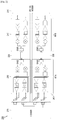
- FIG. 2 illustrates a configuration of a phase calibration device according to an embodiment of the present disclosure.
- the phase calibration device 200 may include a digital modem 210, an RF module, and a member 270.
- the digital modem 210 may output a test signal for calibration to the RF module and, on the basis of a test signal that is fed back in response to output of the test signal through the RF module, may perform phase calibration with regard to each of chain combinations that can be formed by the multi-antenna.
- MIMO multiple input multiple output
- the 2*2 or MIMO structure means that at least two multi-antenna groups 220 and 230 are provided to perform transmission and reception of signals simultaneously.
- the multi-antenna group may be interchangeable with the term "MIMO channel?.
- the RF modem may include one rear RF modem (RFB) 240 and at least two front RF modems (RFA). It is herein assumed, for example, that the RF modem includes two front RF modems 250 and 260. However, operations in the following description are not necessarily limited to the case of two front RF modems.
- the rear RF modem 240 may include a path for processing transmitted signals (transmission path) and a path for processing received signals (reception path) so as to correspond to the two front RF modems 250 and 260, respectively.
- the transmission path may include features for signal type conversion (D/A conversion), amplification, filtering, mixing, etc., with regard to transmitted signals.
- the reception path may include features for mixing, amplification, filtering, signal type conversion (A/D conversion), etc., with regard to received signals.
- the rear RF modem 240 may include operation switches SW#1 and SW#3, which correspond to the two front RF modems 250 and 260, respectively.
- the operation switches SW#1 and SW#3 may connect one of the transmission path and the reception path with the front RF modems 250 and 260. In this case, the operation switches SW#1 and SW#3 neither connect the transmission path to both of the two front RF modems 250 and 260 nor connect the reception path to both thereof.
- the third operation switch SW#3 connects the reception path to the second front RF modem 260. The opposite connection is also possible.
- Each of the front RF modems 250 and 260 may include a path for processing transmitted signals (transmission path) and a path for processing received signals (reception path).
- the transmission path may include features for amplification, filtering, mixing, etc., with regard to transmitted signals.
- the reception path may include features for mixing, amplification, filtering, etc., with regard to received signals.
- the front RF modems 250 and 260 may include operation switches SW#2 and SW#4, which connect the rear RF modem 240, respectively.
- the operation switches SW#2 and SW#4 may connect one of the transmission path and the reception path with the rear RF modem 240. In this case, the operation switches SW#2 and SW#4 cannot connect the same path with the rear RF modem 240.
- the fourth operation switch SW#4 connects the reception path to the rear RF modem 240. The opposite connection is also possible.
- Each of the front RF modems 250 and 260 may transmit or receive signals through a connection with an antenna array, which constitutes a multi-antenna.
- the first front RF modem 250 may be coupled to a first antenna array
- the second front RF modem 260 may be coupled to a second antenna array.
- each of the first and second antenna arrays may include a transmission antenna array and a reception antenna array.
- the transmission antenna array of the first antenna array may constitute forward transmission chains, and the reception antenna array of the first antenna array may constitute reverse reception chains.
- the transmission antenna array of the second antenna array may constitute reverse transmission chains, and the reception antenna array of the second antenna array may constitute forward reception chains.
- a forward transmission chain may be configured so as to correspond to each of transmission antennas, which are included in the transmission antenna array of the first antenna array, and a reverse reception chain may be configured so as to correspond to each of reception antennas, which are included in the reception antenna array of the first antenna array.
- a reverse transmission chain may be configured so as to correspond to each of transmission antennas, which are included in the transmission antenna array of the second antenna array, and a forward reception chain may be configured so as to correspond to each of reception antennas, which are included in the reception antenna array of the second antenna array.
- a combination of the forward transmission chains, which are configured by the transmission antenna array of the first antenna array, and the forward reception chains, which are configured by the reception antenna array of the second antenna array, may be a forward chain combination, which is a phase calibration target.
- a combination of the reverse transmission chains, which are configured by the transmission antenna array of the second antenna array, and the reverse reception chains, which are configured by the reception antenna array of the first antenna array may be a reverse chain combination, which is a phase calibration target.
- the forward chain combination may be configured by coupling of each of the forward transmission chains and each of the forward reception chains
- the reverse chain combination may be configured by coupling of each of the reverse transmission chains and each of the reverse reception chains
- the member 270 may transfer signals (test signals, etc.), which are transmitted or emitted from the forward or reverse transmission chains, to the forward or reverse reception chains. That is, the member 270 may server as a passage for transferring signals between the first antenna array and the second antenna array.
- the material, size, shape, etc., of the member 270 are not particularly limited, as long as the same can transfer radio signals with as little loss as possible. However, it may be preferred to determine the material, size, shape, etc., in view of the place and method to use the same, etc.
- the member 270 may be a waveguide, a metal housing, etc.
- the member 270 has a transmission structure that enables the same to transfer signals while minimizing loss in high frequencies. This makes it possible to fabricate a member 270 that corresponds to a calibration tool, which is suitable for an antenna array mounted on a wireless communication terminal.
- a waveguide as the member 270 may be preferably applied when performing calibration with regard to the full path, including the antenna and the feed line, in the product manufacturing step.
- a metal housing as the member 270 may be preferably applied to calibration, which is to be performed when a performance change resulting from an influence of temperature, voltage, or the like is sensed while the product is used.
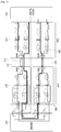
- FIG. 3 illustrates an example of performing phase calibration with regard to a full path in connection with a phase calibration device according to various embodiments.
- the full path for phase calibration may include a forward path 310 and a reverse path 320.
- the forward path 310 may include a transmission path, which is configured by digital antenna group #1 220, and a reception path, which is configured by digital antenna group #2 230.
- the transmission path which is configured by the digital antenna group #1 220, may be formed by an operation switch SW#1 and an operation switch SW#2.
- the operation switch SW#1 connects the transmission path of the rear RF modem 240 with a feed line such that a test signal, which is output by the digital model 210, can be transferred to the first front RF modem 250 through the feed line.
- the operation switch SW#2 connects the feed line with the transmission path of the first front RF modem 250 such that a test signal, which has been transferred from the rear RF modem 240 through the feed line, can be emitted through the forward transmission antenna array that constitutes the first antenna array.
- the test signal can be transmitted with regard to each chain that corresponds to each of the transmission antennas that constitute the forward transmission antenna array.
- the transmission path which is configured by the digital antenna group #2 230, may be formed by an operation switch SW#4 and an operation switch SW#3.
- the operation switch SW#4 connects the reception path of the second front RF modem 260 with a feed line such that a test signal, which has been received through a forward reception antenna array that constitutes the second antenna array, can be transferred to the rear RF modem 240 through the feed line.
- the operation switch SW#3 connects the feed line with the reception path of the rear RF modem 240 such that a test signal, which has been transferred from the second front RF modem 260 through the feed line, can be provided to the digital modem 210 through the reception path of the rear RF modem 240.
- the digital modem 210 performs phase calibration with regard to the corresponding forward chain combination on the basis of a test signal received with regard to each forward chain combination.
- the reverse path 320 may include a transmission path, which is configured by digital antenna group #2 230, and a reception path, which is configured by digital antenna group #1 220.
- the transmission path which is configured by the digital antenna group #2 230, may be formed by an operation switch SW#3 and an operation switch SW#4.
- the operation switch SW#3 connects the transmission path of the rear RF modem 240 with a feed line such that a test signal, which is output by the digital model 210, can be transferred to the second front RF modem 260 through the feed line.
- the operation switch SW#4 connects the feed line with the transmission path of the second front RF modem 260 such that a test signal, which has been transferred from the rear RF modem 240 through the feed line, can be emitted through the reverse transmission antenna array that constitutes the second antenna array.
- the test signal can be transmitted with regard to each chain that corresponds to each of the transmission antennas that constitute the reverse transmission antenna array.
- the transmission path which is configured by the digital antenna group #1 220, may be formed by an operation switch SW#2 and an operation switch SW#1.
- the operation switch SW#2 connects the reception path of the first front RF modem 250 with a feed line such that a test signal, which has been received through a reverse reception antenna array that constitutes the first antenna array, can be transferred to the rear RF modem 240 through the feed line.
- the operation switch SW#1 connects the feed line with the reception path of the rear RF modem 240 such that a test signal, which has been transferred from the first front RF modem 250 through the feed line, can be provided to the digital modem 210 through the reception path of the rear RF modem 240.
- the digital modem 210 performs phase calibration with regard to the corresponding reverse chain combination on the basis of a test signal received with regard to each reverse chain combination.
- FIG. 4 illustrates another example of performing phase calibration with regard to a full path in connection with a phase calibration device according to an embodiment of the present invention.
- FEMs 410 are configured between respective antennas that constitute an antenna array and the front RF module.
- FIG. 5 illustrates a use of a waveguide as a member in connection with a wireless communication terminal according to an embodiment of the present disclosure.
- a waveguide 530 may transfer signals using a structure configured by a hollow center and a conductive wall.
- One of the fasteners provided on both sides of the waveguide 530 receives a test signal input from one of the two front RF modules 510 and 520, and the other fastener outputs the test signal to the other front RF module.
- the fasteners provided on both sides of the waveguide 530 need to be firmly forced against and fastened to antenna arrays of the corresponding front RF modules, respectively, so as not to generate loss of signals that are input and output.
- FIG. 6 illustrates another use of a waveguide as a member in connection with a wireless communication terminal according to an embodiment of the present disclosure.
- the example illustrated may have the same structure as that illustrated in FIG. 5 , except that two front RF modules 610 and 620 are installed in different positions on the wireless communication terminal.
- the two front RF modules 610 and 620 are positioned in parallel with each other on corners of one side of the wireless communication terminal, and the configuration of the waveguide 630, which serves as a test signal transfer path, may have a simpler structure than the waveguide illustrated in FIG. 5 .
- FIG. 7 illustrates a use of a metal housing as a member in connection with a wireless communication terminal according to an embodiment of the present disclosure.
- the metal housing 730 may be used to protect side surfaces of the wireless communication terminal and for the purpose of product design.
- the metal housing 730 may be structured such that side surfaces of the wireless communication terminal are surrounded using a metallic material.
- the metal housing 730 may play the role of a passage for transferring test signals, which are emitted by transmission antennas that constitute a transmission antenna array for the purpose of phase calibration, to reception antennas that constitute a reception antenna array.
- a groove that corresponds to the passage may be formed on the inside of the metal housing 730, particularly on the inner surface thereof that contacts the wireless communication terminal, along an interval between the two front RF modules 710 and 720.
- FIG. 8 illustrates the structure of a waveguide that is to be used as a member for making a path, which corresponds to a wireless interval, among a full path for phase calibration according to an embodiment of the present disclosure.
- the waveguide has a structure configured by a hollow center and a conductive wall, the waveguide being used as a member for transferring test signals, which have been emitted from transmission antennas that constitute a transmission antenna array, to reception antennas that constitute a reception antenna array.
- FIG. 9 illustrates the actual model of a waveguide that can be used as a member for making a path, which corresponds to a wireless interval, among a full path for phase calibration according to an embodiment of the present disclosure.
- FIG. 10 illustrates a control flow for performing phase calibration in connection with a wireless communication terminal according to various embodiments.
- the wireless communication terminal when it is determined that phase calibration is necessary, performs phase calibration in a full path, which corresponds to a forward path, in operation 1010.
- the wireless communication terminal may use various sensors in order to determine whether phase calibration is necessary.
- a temperature sensor may be used to measure the ambient temperature, and it may be determined whether phase calibration is necessary or not in view of a change in the measured temperature.
- the wireless communication terminal may have a forward path configured by a transmission path of multi-antenna group #1, which is configured by a rear RF module and a first front RF module, and a reception path of multi-antenna group #2, which is configured by a second front RF module and the rear RF module.
- the wireless communication terminal performs phase calibration with regard to each of multiple chain combinations included in the forward path. Characteristics (e.g., phase) of a test signal, which is fed back through the full path corresponding to each chain combination included in the forward path, may be analyzed, and phase calibration may be performed with regard to the corresponding chain combination on the basis of the result of analysis.
- the multiple chain combinations refer to combinations of transmission chains, which are configured by transmission antennas that constitute a transmission antenna array of a first antenna array, and reception chains, which are configured by reception antennas that constitute a reception antenna array of a second antenna array.
- the wireless communication terminal After completion of phase calibration related to the forward path, the wireless communication terminal performs phase calibration in a full path, which corresponds to a reverse path, in operation 1020.
- the wireless communication terminal has a reverse path configured by a transmission path of multi-antenna group #2, which is configured by a rear RF module and a second front RF module, and a reception path of multi-antenna group #1, which is configured by a first front RF module and the rear RF module.
- the wireless communication terminal performs phase calibration with regard to each of multiple chain combinations included in the reverse path.
- Characteristics e.g., phase
- phase calibration may be performed with regard to the corresponding chain combination on the basis of the result of analysis.
- the multiple chain combinations refer to combinations of transmission chains, which are configured by transmission antennas that constitute a transmission antenna array of a second antenna array, and reception chains, which are configured by reception antennas that constitute a reception antenna array of a first antenna array.
- phase calibration is preferentially performed with regard to chain combinations in the forward path, and phase calibration is then performed with regard to chain combinations in the reverse path.
- primary calibration is performed with regard to the forward path, which is configured by the transmission path of digital antenna group #1, the path configured by the member, and the reception path of digital antenna group #2
- secondary calibration is performed with regard to the reverse path, which is configured by the transmission path of digital antenna group #2, the path configured by the member, and the reception path of digital antenna group #1.
- phase calibration in the forward path and the reverse path may also be varied. It is also possible to preferentially perform phase calibration with regard to chain combinations in the reverse path and then to perform phase calibration with regard to chain combinations in the forward path.
- phase calibration is performed with regard to the forward path, and phase calibration is then performed with regard to the reverse path.
- phase calibration is then performed with regard to the reverse path.
- FIG. 11 illustrates a control flow for performing phase calibration with regard to a forward path or a reverse path in connection with a wireless communication terminal according to an embodiment of the present disclosure.
- the wireless communication terminal initializes transmission and reception chain indices CHAIN_TX and CHAIN_RX, in order to successively select chain combinations included in a full path (forward path or reverse path), which is the phase calibration target (operation 1110).
- the transmission chain index CHAIN_TX is set to the initial value "0”
- the reception chain index CHAIN_RX is set to the initial value "0”.
- the wireless communication terminal Before or after initializing the transmission and reception chain indices CHAIN_TX and CHAIN_RX, the wireless communication terminal may control operation switches, which are provided in the front and rear RF modules, so as to form a full path (forward path or reverse path) that corresponds to the phase calibration target path.
- the forward path may be formed by selecting a transmission path from transmission/reception paths that constitute multi-antenna group #1 (first MIMO channel) and selecting a reception path from transmission/reception paths that constitute multi-antenna group #2 (second MIMO channel).
- the reverse path may be formed by selecting a transmission path from transmission/reception paths that constitute multi-antenna group #2 (second MIMO channel) and selecting a reception path from transmission/reception paths that constitute multi-antenna group #1 (first MIMO channel).
- the wireless communication terminal performs phase calibration with regard to the full path (forward path or reverse path) (operations 1112 to 1122).
- the phase calibration with regard to the full path may be performed by measuring the phase with regard to each of combinations of all chains that constitute the transmission path and all chains that constitute the reception path, and by conducting calibration using the measured phase as a reference phase value. This requires that a reference phase value be set, chain combinations, the phase of which is to be measured, be selected successively, and the phase that has been measured with regard to the selected chain combination be calibrated using the reference phase value that has been set.
- the wireless communication terminal may measure the phase with regard to a chain combination "CHAIN_TX #n, CHAIN_RX #m”, which has been selected by transmission and reception chain indices CHAIN_TX #n, CHAIN_RX #m (operation 1112).
- "n" which determines the transmission chain index has a range "'0 ⁇ n ⁇ NTX”
- NTX refers to the entire number of transmission chains that constitute a transmission path that forms a full path
- "m which determines the reception chain index
- NRX refers to the entire number of reception chains that constitute a reception path that forms a full path.
- the transmission chain index CHAIN_TX #n is fixed, and the reception chain index CHAIN_RX #m is successively increased, thereby selecting a chain combination.
- the same implementation can also be made by fixing the reception chain index CHAIN_RX #m and successively increasing the transmission chain index CHAIN_TX #n, thereby selecting a chain combination.
- the phase calibration is conducted with regard to a signal that has been fed back in response to a test signal, which has been transmitted to a full path that has been formed.
- the wireless communication terminal may measure the phase on the basis of phase changes of a transmitted test signal and a feedback signal that has been received in response thereto.
- phase is measured with regard to the first chain combination "CHAIN_TX #0, CHAIN_RX #0", because the transmission and reception chain indices CHAIN_TX, CHAIN_RX are set to initial values.
- the wireless communication terminal may set the phase value, which has been measured with regard to the first chain combination, as the reference phase value.
- the reference phase value it is also possible to set the reference phase value as an arbitrary value or to set a phase value, which has been measured with regard to an arbitrarily selected chain combination other than the first chain combination, as the reference phase value.
- the wireless communication terminal calibrates the phase that has been measured with regard to the selected chain combination in operation 1114. If the selected chain combination is the first chain combination, and if the phase value measured with regard to the first chain combination is used as the reference phase value, calibration for the phase value that has been measured with regard to the first chain combination may be omitted. However, if the reference phase value has been set in advance or is provided in another manner, calibration for the phase value that has been measured with regard to the first chain combination is not supposed to be omitted.
- the wireless communication terminal increases the reception chain index CHAIN_RX by 1 in operation 1118, in order to select the next chain combination for phase calibration.
- the wireless communication terminal when a new chain combination is selected, measures the phase with regard to the newly selected chain combination in operation 1112.
- the wireless communication terminal performs calibration with regard to the measured phase value using a preset reference phase value in operation 1114. For example, the wireless communication terminal determines whether phase calibration is necessary or not on the basis of whether the measured phase value is identical to the reference phase value or not.
- the wireless communication terminal may adjust at least one parameter value related to features within the RF module, thereby performing phase calibration, such that the measured phase value is identical or close to the reference phase value.
- the wireless communication terminal may proceed to an operation for performing phase calibration with regard to the next chain combination.
- the wireless communication terminal increases the transmission chain index CHAIN_TX by 1, in order to select the next phase calibration target chain combination, and initializes the reception chain index CHAIN_RX in order to successively select reception chains that constitute a reception path of the forward path in operation 1122.
- the reception chain index CHAIN_RX is set to the initial value "0".
- the wireless communication terminal can perform phase calibration with regard to chain combinations formed by a transmission chain, which corresponds to the updated transmission chain index, and respective reception chains in operations 1112 to 1118.
- the wireless communication terminal successively selects each of combinations formed by transmission chains and reception chains, which constitute a forward or reverse path, thereby performing phase calibration.
- Various schemes for successively selecting target chain combinations for phase calibration from all chain combinations, for the purpose of the phase calibration, may be provided in addition to the previously proposed scheme.
- phase calibration is performed in the order of chain combinations obtained by successively selecting reception chains with reference to one transmission chain.
- Table 1 below gives an example of phase calibration with regard to a forward path.
- multi-antenna group #1 operates as a transmission multi-antenna group
- multi-antenna group #2 operates as a reception antenna group.
- the antenna array included in the transmission multi-antenna group includes three transmission antennas
- the antenna array included in the reception multi-antenna group includes three reception antennas.
- the three transmission antennas correspond to forward transmission chains, respectively, and, in order to identify the transmission chain, each forward transmission chain is endowed with a transmission chain index CHAIN_TX #n.
- the three reception antennas correspond to forward reception chains, respectively, and, in order to identify the reception chain, each forward reception chain is endowed with a reception chain index CHAIN_RX #n.
- Reception chain index (multi-antenna group #2) Measured phase Calibrated phase CHAIN_TX #0 CHAIN_RX #0 FL (DTX#0 + DRX#0) FL (DTX#0 + DRX#0) CHAIN_RX #1 FL (DTX#0 + DRX#1) CHAIN_RX #2 FL (DTX#0 + DRX#2) CHAIN_TX #1 CHAIN_RX #0 FL (DTX#1 + DRX#0) FL (DTX#1 + DRX#0) CHAIN_RX #1 FL (DTX#1 + DRX#1) CHAIN_RX #2 FL (DTX#1 + DRX#2) CHAIN_TX #2 CHAIN_RX #0 FL (DTX#2 + DR
- chain combinations are defined by combining respective transmission antennas, which are positioned on a forward transmission path in a front FR module that constitutes multi-antenna group #1, and respective reception antennas, which are positioned on a forward reception path in a front RF module that constitutes multi-antenna group #2.
- phase FL (DTX#0 + DRX#0) has been measured with regard to a full path that corresponds to chain combination (CHAIN_TX #0, CHAIN_RX #0), and the phase FL has been set as a reference phase value. Then, phase values FL (DTX#0 + DRX#1), FL (DTX#0 + DRX#2), which have been measured with regard to combinations with the remaining forward reception chains with reference to forward transmission chain CHAIN_TX #0, can be calibrated by means of the reference phase value FL (DTX#0 + DRX#0).
- phase calibration of chain combinations by means of CHAIN_TX #0 is completed, phase calibration of chain combinations formed by the next transmission chain index CHAIN_TX #1 is performed.
- Phase FL (DTX#1 + DRX#0) has been measured with regard to a full path that corresponds to chain combination (CHAIN_TX #1, CHAIN_RX #0), and the Phase FL (DTX#1 + DRX#0) has been set as a reference phase value.
- phase values FL (DTX#1 + DRX#1), FL (DTX#1 + DRX#2), which have been measured with regard to combinations with the remaining reception chains with reference to forward transmission chain CHAIN_TX #1, can be calibrated by means of the reference phase value FL (DTX#1 + DRX#0).
- phase calibration of chain combinations by means of CHAIN_TX #1 is completed, phase calibration of chain combinations formed by the next transmission chain index CHAIN_TX #2 is performed.
- Phase FL (DTX#2 + DRX#0) has been measured with regard to a full path that corresponds to chain combination (CHAIN_TX #2, CHAIN_RX #0), and the Phase FL (DTX#2 + DRX#0) has been set as a reference phase value.
- phase values FL (DTX#2 + DRX#1), FL (DTX#2 + DRX#2) which have been measured with regard to combinations with the remaining reception chains with reference to forward transmission chain CHAIN_TX #2, can be calibrated by means of the reference phase value FL (DTX#2 + DRX#0).
- Table 2 below gives an example of phase calibration with regard to a reverse path.
- multi-antenna group #2 operates as a transmission multi-antenna group
- multi-antenna group #1 operates as a reception antenna group.
- the antenna array included in the transmission multi-antenna group includes three transmission antennas
- the antenna array included in the reception multi-antenna group includes three reception antennas.
- the three transmission antennas correspond to reverse transmission chains, respectively, and, in order to identify the transmission chains, each reverse transmission chain is endowed with a transmission chain index CHAIN_TX #n.
- the three reception antennas correspond to reverse reception chains, respectively, and, in order to identify the reception chains, each reverse reception chain is endowed with a reception chain index CHAIN_RX #n.
- Reception chain index (multi-antenna group #1) Measured phase Calibrated phase CHAIN_TX #0 CHAIN_RX #0 RL (DTX#0 + DRX#0) RL (DTX#0 + DRX#0) CHAIN_RX #1 RL (DTX#0 + DRX#1) CHAIN_RX #2 RL (DTX#0 + DRX#2) CHAIN_TX #1 CHAIN_RX #0 RL (DTX#1 + DRX#0) RL (DTX#1 + DRX#0) CHAIN_RX #1 RL (DTX#1 + DRX#1) CHAIN_RX #2 RL (DTX#1 + DRX#2) CHAIN_TX #2 CHAIN_RX #0
- chain combinations are defined by combining respective transmission antennas, which are positioned on a reverse transmission path in a front FR module that constitutes multi-antenna group #2, and respective reception antennas, which are positioned on a reverse reception path in a front RF module that constitutes multi-antenna group #1.
- phase RL (DTX#0 + DRX#0) has been measured with regard to a full path that corresponds to chain combination (CHAIN_TX #0, CHAIN_RX #0), and the phase RL (DTX#0 + DRX#0) has been set as a reference phase value. Then, phase values RL (DTX#0 + DRX#1), RL (DTX#0 + DRX#2), which have been measured with regard to combinations with the remaining reverse reception chains with reference to reverse transmission chain CHAIN_TX #0, can be calibrated by means of the reference phase value RL (DTX#0 + DRX#0).
- phase calibration of chain combinations by means of CHAIN_TX #0 is completed, phase calibration of chain combinations formed by the next transmission chain index CHAIN_TX #1 is performed.
- Phase RL (DTX#1 + DRX#0) has been measured with regard to a full path that corresponds to chain combination (CHAIN_TX #1, CHAIN_RX #0), and the phase RL (DTX#1 + DRX#0) has been set as a reference phase value.
- phase values RL (DTX#1 + DRX#1), RL (DTX#1 + DRX#2), which have been measured with regard to combinations with the remaining reception chains with reference to transmission chain CHAIN_TX #1, can be calibrated by means of the reference phase value RL (DTX#1 + DRX#0).
- phase calibration of chain combinations by means of CHAIN_TX #1 is completed, phase calibration of chain combinations formed by the next transmission chain index CHAIN_TX #2 is performed.
- Phase RL (DTX#2 + DRX#0) has been measured with regard to a full path that corresponds to chain combination (CHAIN_TX #2, CHAIN_RX #0), and the phase RL (DTX#2 + DRX#0) has been set as a reference phase value.
- phase values RL (DTX#2 + DRX#1), RL (DTX#2 + DRX#2), which have been measured with regard to combinations with the remaining reception chains with reference to transmission chain CHAIN_TX #2, can be calibrated by means of the reference phase value RL (DTX#2 + DRX#0).
- phase calibration is performed in the order of chain combinations obtained by successively selecting transmission chains with reference to one reception chain.
- Table 3 below gives an example of phase calibration with regard to a forward path.
- multi-antenna group #1 operates as a transmission multi-antenna group
- multi-antenna group #2 operates as a reception antenna group.
- the antenna array included in the transmission multi-antenna group includes three transmission antennas
- the antenna array included in the reception multi-antenna group includes three reception antennas.
- the three transmission antennas correspond to forward transmission chains, respectively, and, in order to identify the transmission chains, each forward transmission chain is endowed with a transmission chain index CHAIN_TX #n.
- the three reception antennas correspond to forward reception chains, respectively, and, in order to identify the reception chains, each forward reception chain is endowed with a reception chain index CHAIN_RX #n.
- chain combinations are defined by combining respective reception antennas, which are positioned on a forward reception path in a front FR module that constitutes multi-antenna group #2, and respective transmission antennas, which are positioned on a forward transmission path in a front RF module that constitutes multi-antenna group #1.
- phase FL (DRX#0 + DTX#0) has been measured with regard to a full path that corresponds to chain combination (CHAIN_RX #0, CHAIN_TX #0), and the phase FL (DRX#0 + DTX#0) has been set as a reference phase value. Then, phase values FL (DRX#0 + DTX#1), FL (DRX#0 + DTX#2), which have been measured with regard to combinations with the remaining transmission chains with reference to reception chain CHAIN_RX #0, can be calibrated by means of the reference phase value FL (DRX#0 + DTX#0).
- phase calibration of chain combinations by means of CHAIN_RX #0 is completed, phase calibration of chain combinations formed by the next reception chain index CHAIN_RX #1 is performed.
- Phase FL (DRX#1 + DTX#0) has been measured with regard to a full path that corresponds to chain combination (CHAIN_RX #1, CHAIN_TX #0), and the (DRX#1 + DTX#0) has been set as a reference phase value.
- phase values FL (DRX#1 + DTX#1), FL (DRX#1 + DTX#2) which have been measured with regard to combinations with the remaining transmission chains with reference to reception chain CHAIN_RX #1, can be calibrated by means of the reference phase value FL (DRX#1 + DTX#0).
- phase calibration of chain combinations by means of CHAIN_RX #1 is completed, phase calibration of chain combinations formed by the next reception chain index CHAIN_RX #2 is performed. That is, phase FL (DRX#2 + DTX#0) has been measured with regard to a full path that corresponds to chain combination (CHAIN_RX #2, CHAIN_TX #0), and the phase FL (DRX#2 + DTX#0) has been set as a reference phase value.
- phase values FL (DRX#2 + DTX#1), FL (DRX#2 + DTX#2), which have been measured with regard to combinations with the remaining transmission chains with reference to reception chain CHAIN_RX #2, can be calibrated by means of the reference phase value FL (DRX#2 + DTX#0).
- Table 4 below gives an example of phase calibration with regard to a reverse path.
- multi-antenna group #1 operates as a reception multi-antenna group
- multi-antenna group #2 operates as a transmission antenna group.
- the antenna array included in the transmission multi-antenna group includes three transmission antennas
- the antenna array included in the reception multi-antenna group includes three reception antennas.
- the three transmission antennas correspond to reverse transmission chains, respectively, and, in order to identify the transmission chains, each reverse transmission chain is endowed with a transmission chain index CHAIN_TX #n.
- the three reception antennas correspond to reverse reception chains, respectively, and, in order to identify the reception chains, each reverse reception chain is endowed with a reception chain index CHAIN_RX #n.
- Reception chain index multi-antenna group #1
- Transmission chain index multi-antenna group #2
- Measured phase Calibrated phase CHAIN_RX #0 CHAIN_TX #0 RL (DRX#0 + DTX#0) RL (DRX#0 + DTX#0) CHAIN_TX #1 RL (DRX#0 + DTX#1) CHAIN_TX #2 RL (DRX#0 + DTX#2) CHAIN_RX #1 CHAIN_TX #0 RL (DRX#1 + DTX#0) RL (DRX#1 + DTX#0) CHAIN_TX #1 RL (DRX#1 + DTX#1) CHAIN_TX #2 RL (DRX#1 + DTX#2) CHAIN_TX #1 RL (DRX#1 +
- chain combinations are defined by combining respective transmission antennas, which are positioned on a reverse transmission path in a front FR module that constitutes multi-antenna group #2, and respective reception antennas, which are positioned on a reverse reception path in a front RF module that constitutes multi-antenna group #1.
- phase RL (DRX#0 + DTX#0) has been measured with regard to a full path that corresponds to chain combination (CHAIN_RX #0, CHAIN_TX #0), and the phase RL (DRX#0 + DTX#0) has been set as a reference phase value. Then, phase values RL (DRX#0 + DTX#1), RL (DTX#0 + DTX#2), which have been measured with regard to combinations with the remaining reverse transmission chains with reference to reverse reception chain CHAIN_RX #0, can be calibrated by means of the reference phase value RL (DTX#0 + DRX#0).
- phase calibration of chain combinations by means of CHAIN_RX #0 is completed, phase calibration of chain combinations formed by the next reception chain index CHAIN_RX #1 is performed.
- Phase RL (DRX#1 + DTX#0) has been measured with regard to a full path that corresponds to chain combination (CHAIN_RX #1, CHAIN_TX #0), and the phase RL (DRX#1 + DTX#0) has been set as a reference phase value.
- phase values RL (DRX#1 + DTX#1), RL (DRX#1 + DTX#2), which have been measured with regard to combinations with the remaining transmission chains with reference to reception chain CHAIN_RX #1, can be calibrated by means of the reference phase value FL (DRX#1 + DTX#0).
- phase calibration of chain combinations by means of CHAIN_RX #1 is completed, phase calibration of chain combinations formed by the next reception chain index CHAIN_RX #2 is performed.
- Phase RL (DRX#2 + DTX#0) has been measured with regard to a full path that corresponds to chain combination (CHAIN_RX #2, CHAIN_TX #0), and the phase RL (DRX#2 + DTX#0) has been set as a reference phase value.
- phase values RL (DRX#2 + DTX#1), RL (DRX#2 + DTX#2), which have been measured with regard to combinations with the remaining transmission chains with reference to reception chain CHAIN_RX #2, can be calibrated by means of the reference phase value RL (DRX#2 + DTX#0).
- FIG. 12 illustrates a control flow for performing calibration with regard to a digital area in connection with a wireless communication terminal according to various embodiments.
- the wireless communication terminal sets a calibration set register (CSR) in operation 1210.
- the wireless communication terminal sets a default power down (PD) value in operation 1212.
- the wireless communication terminal measures DC values related to an I channel and a Q channel on the basis of the CSR and the default power down value that have been set (operation 1214).
- the wireless communication terminal determines whether the measured DC value is larger than 10 mV in operation 1216. When the measured DC value is larger than 10mV, the wireless communication terminal reduces the DAC register value on the basis of the previously set default PD value in operation 1218. The wireless communication terminal measures the DV value related to the I and Q channels on the basis of the reduced DAC register value in operation 1214.
- the wireless communication terminal determines whether the measured DC value is smaller than -10 mV in operation 1220. When the measured DC value is smaller than - 10mV, the wireless communication terminal increases the DAC register value on the basis of the previously set default PD value in operation 1222. The wireless communication terminal measures the DV value related to the I and Q channels on the basis of the increased DAC register value in operation 1214.
- the wireless communication terminal completes the operation of calibrating the DC in the reception path.
Landscapes
- Engineering & Computer Science (AREA)
- Computer Networks & Wireless Communication (AREA)
- Signal Processing (AREA)
- Physics & Mathematics (AREA)
- Electromagnetism (AREA)
- Variable-Direction Aerials And Aerial Arrays (AREA)
- Radio Transmission System (AREA)
Claims (11)
- Dispositif de terminal de communication sans fil ayant une multi-antenne, le dispositif de terminal de communication sans fil comprenant :un premier module de radiofréquence, RF, (120, 250) comprenant un premier réseau d'antennes (126) ;un deuxième module de RF (130, 260) comprenant un deuxième réseau d'antennes (136) ;un troisième module de RF (110, 240) connecté à chacun du premier module de RF (120) et du deuxième module de RF (130, 260) par un câble ayant une longueur prédéterminée ; etun modem numérique (210) configuré pour :délivrer en sortie un premier signal de test au troisième module de RF (110, 240),recevoir un deuxième signal de test à partir du troisième module de RF (110, 240), en réponse au premier signal de test, etétalonner une valeur de phase pour chacune de premières combinaisons de chaînes formées par le premier réseau d'antennes (126) et le deuxième réseau d'antennes (136), sur la base du premier signal de test et du deuxième signal de test ; etun élément (270) configuré pour former un trajet de transmission et un trajet de réception entre le premier module de RF (120, 250) et le deuxième module de RF (130, 260),où le trajet de transmission est configuré par le troisième module de RF (110, 240) et le premier module de RF (120, 250) pour transmettre le premier signal de test, etoù le trajet de réception est configuré par le deuxième module de RF (130, 260) et le troisième module de RF (110, 240) pour recevoir le premier signal de test et délivrer en sortie le deuxième signal de test au modem numérique (210).
- Dispositif de terminal de communication sans fil selon la revendication 1,où au moins l'un parmi le premier réseau d'antennes (126) et le deuxième réseau d'antennes (136) est positionné à un coin du dispositif de terminal de communication sans fil, etoù une longueur d'un premier câble est différente de la longueur d'un deuxième câble, le premier câble connectant le premier module de RF (120, 250) au troisième module de RF (110, 240) et le deuxième câble connectant le deuxième module de RF (120, 260) au troisième module de RF (110, 240).
- Dispositif de terminal de communication sans fil selon la revendication 2,où l'élément (270) comprend un guide d'ondes, etoù des attaches pourvues des deux côtés du guide d'ondes sont fixées une à une au premier réseau d'antennes (126) et au deuxième réseau d'antennes (136).
- Dispositif de terminal de communication sans fil selon la revendication 2,où l'élément (270) comprend un boîtier métallique, etoù le boîtier métallique est fixé de manière à entourer quatre surfaces latérales du dispositif de terminal de communication sans fil.
- Dispositif de terminal de communication sans fil selon la revendication 1, où le modem numérique (210) est configuré en outre pour :sélectionner une première antenne dans le premier réseau d'antennes (126) et une deuxième antenne dans le deuxième réseau d'antennes (136),mesurer une valeur de phase pour une combinaison de chaînes formée sur la base de la première antenne sélectionnée et de la deuxième antenne sélectionnée,définir la valeur de phase mesurée en tant que valeur de phase de référence, etétalonner une valeur de phase pour chacune de deuxièmes combinaisons de chaînes sur la base de la valeur de phase de référence, les deuxièmes combinaisons de chaînes étant formées sur la base de la première antenne sélectionnée et d'antennes restantes du deuxième réseau d'antennes (136).
- Dispositif de terminal de communication sans fil selon la revendication 1,où le modem numérique (210) est configuré en outre pour :délivrer en sortie un troisième signal de test au troisième module de RF (110, 240),recevoir un quatrième signal de test à partir du troisième module de RF (110, 240), en réponse au troisième signal de test, etétalonner une valeur de phase pour chacune de deuxièmes combinaisons de chaînes formées par le premier réseau d'antennes (126) et le deuxième réseau d'antennes (136), sur la base du troisième signal de test et du quatrième signal de test,où un trajet de transmission pour transmettre le troisième signal de test est configuré par le troisième module de RF (110, 240) et le deuxième module de RF (130, 260), etoù un trajet de réception pour recevoir le troisième signal de test et délivrer en sortie le quatrième signal de test au modem numérique (210) est configuré par le premier module de RF (120, 250) et le troisième module de RF (110, 240).
- Dispositif de terminal de communication sans fil selon la revendication 6, où le modem numérique (210) est configuré en outre pour :sélectionner une première antenne dans le deuxième réseau d'antennes (136) et une deuxième antenne dans le premier réseau d'antennes (126),mesurer une valeur de phase pour une combinaison de chaînes formée sur la base de la première antenne sélectionnée et de la deuxième antenne sélectionnée,définir la valeur de phase mesurée en tant que valeur de phase de référence, etétalonner une valeur de phase pour chacune de deuxièmes combinaisons de chaînes sur la base de la valeur de phase de référence, les deuxièmes combinaisons de chaînes étant formées sur la base de la première antenne sélectionnée et d'antennes restantes dans le premier réseau d'antennes (126).
- Procédé pour étalonner une phase dans un dispositif de terminal de communication sans fil comprenant un premier module de radiofréquence, RF, (120, 250) qui comprend un premier réseau d'antennes (126), un deuxième module de RF (130, 260) comprenant un deuxième réseau d'antennes (136), un troisième module de RF (110, 240), connecté à chacun du premier module de RF (120, 250) et du deuxième module de RF (130, 260) par un câble ayant une longueur prédéterminée et un modèle numérique (210), le procédé comprenant :délivrer en sortie, par le modem numérique (210), un premier signal de test au troisième module de RF (110, 240) ;recevoir, par le modem numérique (210), un deuxième signal de test à partir du troisième module de RF (110, 240), en réponse au premier signal de test ; etétalonner, par le modem numérique (210), une valeur de phase pour chacune de premières combinaisons de chaînes formées par le premier réseau d'antennes (126) et le deuxième réseau d'antennes (136) sur la base du premier signal de test et du deuxième signal de test,où un trajet de transmission et un trajet de réception entre le premier module de RF (120, 250) et le deuxième module de RF (130, 260) sont formés par un élément (270) dans le dispositif de terminal de communication sans fil,où le trajet de transmission est configuré par le troisième module de RF (110, 240) et le premier module de RF (120, 250) pour transmettre le premier signal de test, etoù le trajet de réception est configuré par le deuxième module de RF (130, 260) et le troisième module de RF (110, 240) pour recevoir le premier signal de test et délivrer en sortie le deuxième signal de test au modem numérique (210).
- Procédé selon la revendication 8, où l'étalonnage de la valeur de phase pour chacune des premières combinaisons de chaînes comprend :sélectionner, par le modèle numérique (210), une première antenne dans le premier réseau d'antennes (126) et une deuxième antenne dans le deuxième réseau d'antennes (136) ;mesurer, par le modem numérique (210), une valeur de phase pour une combinaison de chaînes formée sur la base de la première antenne sélectionnée et de la deuxième antenne sélectionnée ;définir, par le modem numérique (210), la valeur de phase mesurée en tant que valeur de phase de référence ; etétalonner, par le modem numérique (210), une valeur de phase pour chacune de deuxièmes combinaisons de chaînes sur la base de la valeur de phase de référence, les deuxièmes combinaisons de chaînes étant formées sur la base de la première antenne sélectionnée et d'antennes restantes dans le deuxième réseau d'antennes (136).
- Procédé selon la revendication 8, comprenant en outre :délivrer en sortie, par le modem numérique (210), un troisième signal de test au troisième module de RF (110, 240),recevoir, par le modem numérique (210), un quatrième signal de test du troisième module de RF (110, 240), en réponse au troisième signal de test, etétalonner, par le modem numérique (210), une valeur de phase pour chacune de deuxièmes combinaisons de chaînes formées par le premier réseau d'antennes (126) et le deuxième réseau d'antennes (136), sur la base du troisième signal de test et du quatrième signal de test,où un trajet de transmission pour transmettre le troisième signal de test est configuré par le troisième module de RF (110, 240) et le deuxième module de RF (130, 260), etoù un trajet de réception pour recevoir le troisième signal de test et délivrer en sortie le quatrième signal de test au modem numérique (210) est configuré par le premier module de RF (120, 250) et le troisième module de RF (110, 240).
- Procédé selon la revendication 10, où, l'étalonnage de la valeur de phase pour chacune des deuxièmes combinaisons de chaînes comprendsélectionner, par le modem numérique (210), une première antenne dans le deuxième réseau d'antennes (136) et une deuxième antenne dans le premier réseau d'antennes (126) ;mesurer, par le modem numérique (210), une valeur de phase pour une première combinaison de chaînes formée sur la base de la première antenne sélectionnée et de la deuxième antenne sélectionnée ;définir, par le modem numérique (210), la valeur de phase mesurée en tant que valeur de phase de référence ; etétalonner une valeur de phase pour chacune de deuxièmes combinaisons de chaînes sur la base de la valeur de phase de référence, les deuxièmes combinaisons de chaînes étant formées sur la base de la première antenne sélectionnée et d'antennes restantes dans le premier réseau d'antennes (126).
Applications Claiming Priority (2)
| Application Number | Priority Date | Filing Date | Title |
|---|---|---|---|
| KR1020150097571A KR102459683B1 (ko) | 2015-07-09 | 2015-07-09 | 무선 주파수 모듈에서의 교정장치 및 방법 |
| PCT/KR2016/007515 WO2017007292A1 (fr) | 2015-07-09 | 2016-07-11 | Procédé et appareil d'étalonnage dans un module radiofréquence |
Publications (3)
| Publication Number | Publication Date |
|---|---|
| EP3320629A1 EP3320629A1 (fr) | 2018-05-16 |
| EP3320629A4 EP3320629A4 (fr) | 2018-07-11 |
| EP3320629B1 true EP3320629B1 (fr) | 2020-05-20 |
Family
ID=57686165
Family Applications (1)
| Application Number | Title | Priority Date | Filing Date |
|---|---|---|---|
| EP16821698.4A Active EP3320629B1 (fr) | 2015-07-09 | 2016-07-11 | Procédé et appareil d'étalonnage dans un module radiofréquence |
Country Status (5)
| Country | Link |
|---|---|
| US (1) | US10505647B2 (fr) |
| EP (1) | EP3320629B1 (fr) |
| KR (1) | KR102459683B1 (fr) |
| CN (1) | CN107852249B (fr) |
| WO (1) | WO2017007292A1 (fr) |
Families Citing this family (12)
| Publication number | Priority date | Publication date | Assignee | Title |
|---|---|---|---|---|
| CN107889556B (zh) * | 2015-07-10 | 2022-03-22 | 梁平 | 无线多天线系统中上行链路和下行链路信道状态信息的校准方法 |
| KR102520406B1 (ko) * | 2016-12-23 | 2023-04-12 | 삼성전자 주식회사 | 대용량 안테나 시스템에서 안테나 위상 보정 방법 및 장치 |
| KR102495595B1 (ko) * | 2017-11-20 | 2023-02-06 | 삼성전자주식회사 | 전자 장치 및 전자 장치에서의 송신 신호의 피드백 경로 제공 방법 |
| CN111801848A (zh) * | 2018-01-05 | 2020-10-20 | 维斯普瑞公司 | 角天线阵列设备、系统和方法 |
| JP6923478B2 (ja) * | 2018-03-28 | 2021-08-18 | 日立Astemo株式会社 | レーダセンサ |
| KR102422190B1 (ko) | 2018-03-29 | 2022-07-18 | 삼성전자주식회사 | 통신 모듈의 캘리브레이션을 수행하기 위한 장치 및 방법 |
| KR102441958B1 (ko) * | 2018-05-23 | 2022-09-08 | 삼성전자 주식회사 | 무선 통신 회로를 검사하기 위한 전자 장치 및 방법 |
| WO2020017290A1 (fr) * | 2018-07-20 | 2020-01-23 | 京セラ株式会社 | Dispositif électronique, procédé de commande de dispositif électronique et programme de commande de dispositif électronique |
| KR102388027B1 (ko) | 2018-12-26 | 2022-04-19 | 삼성전자 주식회사 | 무선통신 모듈의 시험 방법 및 상기 무선통신 모듈을 포함하는 전자 장치 |
| KR102940188B1 (ko) * | 2020-01-09 | 2026-03-17 | 삼성전자 주식회사 | 위상 배열 안테나를 캘리브레이션하기 위한 방법 및 장치 |
| WO2021230779A1 (fr) * | 2020-05-11 | 2021-11-18 | Telefonaktiebolaget Lm Ericsson (Publ) | Agencement d'essai d'émetteur-récepteur radio à micro-ondes |
| KR20220103559A (ko) | 2021-01-15 | 2022-07-22 | 삼성전자주식회사 | 무선 통신 시스템에서 오차를 보상하기 위한 장치 및 방법 |
Family Cites Families (19)
| Publication number | Priority date | Publication date | Assignee | Title |
|---|---|---|---|---|
| US6148219A (en) * | 1997-02-18 | 2000-11-14 | Itt Manufacturing Enterprises, Inc. | Positioning system for CDMA/PCS communications system |
| US7031669B2 (en) * | 2002-09-10 | 2006-04-18 | Cognio, Inc. | Techniques for correcting for phase and amplitude offsets in a MIMO radio device |
| US7486740B2 (en) | 2004-04-02 | 2009-02-03 | Qualcomm Incorporated | Calibration of transmit and receive chains in a MIMO communication system |
| JP4524147B2 (ja) | 2004-06-30 | 2010-08-11 | 京セラ株式会社 | 通信装置、キャリブレーション方法及びプログラム |
| EP1791278A1 (fr) | 2005-11-29 | 2007-05-30 | Interuniversitair Microelektronica Centrum (IMEC) | Procédé et dispositif de calibration pour systèmes MIMO |
| US20090117859A1 (en) * | 2006-04-07 | 2009-05-07 | Belair Networks Inc. | System and method for frequency offsetting of information communicated in mimo based wireless networks |
| US7620373B2 (en) * | 2006-06-23 | 2009-11-17 | Sierra Monolithics, Inc. | Apparatus and method for calibration of gain and/or phase imbalance and/or DC offset in a communication system |
| US8010064B2 (en) * | 2008-03-13 | 2011-08-30 | Samsung Electro—Mechanics Company, Ltd. | Systems and methods for transmitter calibration |
| JP4544350B2 (ja) * | 2008-07-15 | 2010-09-15 | ソニー株式会社 | 無線通信装置及び無線通信方法、並びにコンピュータ・プログラム |
| US8045926B2 (en) * | 2008-10-15 | 2011-10-25 | Nokia Siemens Networks Oy | Multi-transceiver architecture for advanced Tx antenna monitoring and calibration in MIMO and smart antenna communication systems |
| US8160501B1 (en) * | 2009-03-10 | 2012-04-17 | Sprint Communications Company L.P. | Test device for gain level determination of wireless repeater systems |
| US8086174B2 (en) * | 2009-04-10 | 2011-12-27 | Nextivity, Inc. | Short-range cellular booster |
| US9014008B2 (en) * | 2009-08-12 | 2015-04-21 | Empire Technology Development Llc | Forward-looking probabilistic statistical routing for wireless ad-hoc networks with lossy links |
| US8358577B1 (en) * | 2009-12-10 | 2013-01-22 | Sprint Communications Company L.P. | Using wireless links to offload backhaul communications |
| EP2372836B1 (fr) | 2010-03-18 | 2017-05-03 | Alcatel Lucent | Étalonnage d'un réseau d'antennes |
| EP2564531B2 (fr) * | 2010-04-28 | 2017-03-01 | Telefonaktiebolaget LM Ericsson (publ) | Réseau d'accès optique |
| US20130109324A1 (en) * | 2011-10-28 | 2013-05-02 | Broadcom Corporation | Reverse channel estimation for rf transceiver with beamforming antenna |
| US9621330B2 (en) | 2011-11-30 | 2017-04-11 | Maxlinear Asia Singapore Private Limited | Split microwave backhaul transceiver architecture with coaxial interconnect |
| US9705478B2 (en) * | 2013-08-01 | 2017-07-11 | Qorvo Us, Inc. | Weakly coupled tunable RF receiver architecture |
-
2015
- 2015-07-09 KR KR1020150097571A patent/KR102459683B1/ko active Active
-
2016
- 2016-07-11 EP EP16821698.4A patent/EP3320629B1/fr active Active
- 2016-07-11 US US15/206,720 patent/US10505647B2/en active Active
- 2016-07-11 WO PCT/KR2016/007515 patent/WO2017007292A1/fr not_active Ceased
- 2016-07-11 CN CN201680040592.7A patent/CN107852249B/zh active Active
Non-Patent Citations (1)
| Title |
|---|
| None * |
Also Published As
| Publication number | Publication date |
|---|---|
| CN107852249B (zh) | 2021-03-12 |
| US10505647B2 (en) | 2019-12-10 |
| KR20170006639A (ko) | 2017-01-18 |
| EP3320629A1 (fr) | 2018-05-16 |
| EP3320629A4 (fr) | 2018-07-11 |
| KR102459683B1 (ko) | 2022-10-28 |
| US20170012349A1 (en) | 2017-01-12 |
| CN107852249A (zh) | 2018-03-27 |
| WO2017007292A1 (fr) | 2017-01-12 |
Similar Documents
| Publication | Publication Date | Title |
|---|---|---|
| EP3320629B1 (fr) | Procédé et appareil d'étalonnage dans un module radiofréquence | |
| CN212588326U (zh) | 射频PA Mid器件、射频系统和通信设备 | |
| US8170510B2 (en) | Minimizing mutual coupling | |
| US8260234B2 (en) | Apparatus and method for calibration in multi-antenna system | |
| CN115088339B (zh) | 一种波束对训练方法及通信装置 | |
| EP3309980B1 (fr) | Dispositif sans fil et procédé d'étalonnage de canal de fréquence radio | |
| CN107925150A (zh) | 用于校准天线阵列的技术 | |
| CN104969412B (zh) | 用于多频带操作的天线装置 | |
| CN212588327U (zh) | 射频PA Mid器件、射频收发系统和通信设备 | |
| CN108471324A (zh) | 电子设备、通信装置和信号处理方法 | |
| CN212811690U (zh) | 射频l-drx器件、射频收发系统和通信设备 | |
| CN103916168B (zh) | 一种天线校准方法及装置 | |
| US20220201600A1 (en) | Radio communication devices and methods for performing radio communication | |
| EP2932609B1 (fr) | Procédé et dispositif de réception radio utilisant un appareil d'accord d'antenne et une pluralité d'antennes | |
| CN113726358A (zh) | 射频PA Mid器件、射频系统和通信设备 | |
| CN113726357A (zh) | 射频PA Mid器件、射频收发系统和通信设备 | |
| WO2013091581A1 (fr) | Antenne active et procédé de traitement de signal correspondant | |
| CN116711364A (zh) | 信道信息获取方法及相关设备 | |
| CN108540181A (zh) | 一种天线校准的方法及装置 | |
| CN106105064A (zh) | 在大规模mimo无线通信系统中使用的天线校准方法和装置 | |
| CN103916864B (zh) | 一种无线直放站及其传输信号方法 | |
| CN102045123B (zh) | 实现时分双工无线通信系统信道互易的射频校准方法和装置 | |
| EP1496567A1 (fr) | Dispositif de calibration de transmission et réception des signeaux dans un système de radiocommunication | |
| IT202100014927A1 (it) | Sistemi e metodi per la generazione di dati di calibrazione in moduli antenna attiva aventi all'interno schiere di filtri lato antenna | |
| CN103916176B (zh) | 一种无线直放站及其天线校准方法 |
Legal Events
| Date | Code | Title | Description |
|---|---|---|---|
| STAA | Information on the status of an ep patent application or granted ep patent |
Free format text: STATUS: THE INTERNATIONAL PUBLICATION HAS BEEN MADE |
|
| PUAI | Public reference made under article 153(3) epc to a published international application that has entered the european phase |
Free format text: ORIGINAL CODE: 0009012 |
|
| STAA | Information on the status of an ep patent application or granted ep patent |
Free format text: STATUS: REQUEST FOR EXAMINATION WAS MADE |
|
| 17P | Request for examination filed |
Effective date: 20180125 |
|
| AK | Designated contracting states |
Kind code of ref document: A1 Designated state(s): AL AT BE BG CH CY CZ DE DK EE ES FI FR GB GR HR HU IE IS IT LI LT LU LV MC MK MT NL NO PL PT RO RS SE SI SK SM TR |
|
| AX | Request for extension of the european patent |
Extension state: BA ME |
|
| REG | Reference to a national code |
Ref country code: DE Ref legal event code: R079 Ref document number: 602016036816 Country of ref document: DE Free format text: PREVIOUS MAIN CLASS: H04B0017140000 Ipc: H04B0017210000 |
|
| A4 | Supplementary search report drawn up and despatched |
Effective date: 20180613 |
|
| RIC1 | Information provided on ipc code assigned before grant |
Ipc: H04B 17/21 20150101AFI20180607BHEP Ipc: H04B 17/12 20150101ALI20180607BHEP |
|
| DAV | Request for validation of the european patent (deleted) | ||
| DAX | Request for extension of the european patent (deleted) | ||
| STAA | Information on the status of an ep patent application or granted ep patent |
Free format text: STATUS: EXAMINATION IS IN PROGRESS |
|
| 17Q | First examination report despatched |
Effective date: 20190124 |
|
| GRAP | Despatch of communication of intention to grant a patent |
Free format text: ORIGINAL CODE: EPIDOSNIGR1 |
|
| STAA | Information on the status of an ep patent application or granted ep patent |
Free format text: STATUS: GRANT OF PATENT IS INTENDED |
|
| INTG | Intention to grant announced |
Effective date: 20191212 |
|
| GRAS | Grant fee paid |
Free format text: ORIGINAL CODE: EPIDOSNIGR3 |
|
| GRAA | (expected) grant |
Free format text: ORIGINAL CODE: 0009210 |
|
| STAA | Information on the status of an ep patent application or granted ep patent |
Free format text: STATUS: THE PATENT HAS BEEN GRANTED |
|
| AK | Designated contracting states |
Kind code of ref document: B1 Designated state(s): AL AT BE BG CH CY CZ DE DK EE ES FI FR GB GR HR HU IE IS IT LI LT LU LV MC MK MT NL NO PL PT RO RS SE SI SK SM TR |
|
| REG | Reference to a national code |
Ref country code: GB Ref legal event code: FG4D |
|
| REG | Reference to a national code |
Ref country code: CH Ref legal event code: EP |
|
| REG | Reference to a national code |
Ref country code: DE Ref legal event code: R096 Ref document number: 602016036816 Country of ref document: DE |
|
| REG | Reference to a national code |
Ref country code: AT Ref legal event code: REF Ref document number: 1273308 Country of ref document: AT Kind code of ref document: T Effective date: 20200615 |
|
| REG | Reference to a national code |
Ref country code: LT Ref legal event code: MG4D |
|
| REG | Reference to a national code |
Ref country code: NL Ref legal event code: MP Effective date: 20200520 |
|
| PG25 | Lapsed in a contracting state [announced via postgrant information from national office to epo] |
Ref country code: PT Free format text: LAPSE BECAUSE OF FAILURE TO SUBMIT A TRANSLATION OF THE DESCRIPTION OR TO PAY THE FEE WITHIN THE PRESCRIBED TIME-LIMIT Effective date: 20200921 Ref country code: GR Free format text: LAPSE BECAUSE OF FAILURE TO SUBMIT A TRANSLATION OF THE DESCRIPTION OR TO PAY THE FEE WITHIN THE PRESCRIBED TIME-LIMIT Effective date: 20200821 Ref country code: FI Free format text: LAPSE BECAUSE OF FAILURE TO SUBMIT A TRANSLATION OF THE DESCRIPTION OR TO PAY THE FEE WITHIN THE PRESCRIBED TIME-LIMIT Effective date: 20200520 Ref country code: NO Free format text: LAPSE BECAUSE OF FAILURE TO SUBMIT A TRANSLATION OF THE DESCRIPTION OR TO PAY THE FEE WITHIN THE PRESCRIBED TIME-LIMIT Effective date: 20200820 Ref country code: IS Free format text: LAPSE BECAUSE OF FAILURE TO SUBMIT A TRANSLATION OF THE DESCRIPTION OR TO PAY THE FEE WITHIN THE PRESCRIBED TIME-LIMIT Effective date: 20200920 Ref country code: SE Free format text: LAPSE BECAUSE OF FAILURE TO SUBMIT A TRANSLATION OF THE DESCRIPTION OR TO PAY THE FEE WITHIN THE PRESCRIBED TIME-LIMIT Effective date: 20200520 Ref country code: LT Free format text: LAPSE BECAUSE OF FAILURE TO SUBMIT A TRANSLATION OF THE DESCRIPTION OR TO PAY THE FEE WITHIN THE PRESCRIBED TIME-LIMIT Effective date: 20200520 |
|
| PG25 | Lapsed in a contracting state [announced via postgrant information from national office to epo] |
Ref country code: BG Free format text: LAPSE BECAUSE OF FAILURE TO SUBMIT A TRANSLATION OF THE DESCRIPTION OR TO PAY THE FEE WITHIN THE PRESCRIBED TIME-LIMIT Effective date: 20200820 Ref country code: LV Free format text: LAPSE BECAUSE OF FAILURE TO SUBMIT A TRANSLATION OF THE DESCRIPTION OR TO PAY THE FEE WITHIN THE PRESCRIBED TIME-LIMIT Effective date: 20200520 Ref country code: RS Free format text: LAPSE BECAUSE OF FAILURE TO SUBMIT A TRANSLATION OF THE DESCRIPTION OR TO PAY THE FEE WITHIN THE PRESCRIBED TIME-LIMIT Effective date: 20200520 Ref country code: HR Free format text: LAPSE BECAUSE OF FAILURE TO SUBMIT A TRANSLATION OF THE DESCRIPTION OR TO PAY THE FEE WITHIN THE PRESCRIBED TIME-LIMIT Effective date: 20200520 |
|
| REG | Reference to a national code |
Ref country code: AT Ref legal event code: MK05 Ref document number: 1273308 Country of ref document: AT Kind code of ref document: T Effective date: 20200520 |
|
| PG25 | Lapsed in a contracting state [announced via postgrant information from national office to epo] |
Ref country code: AL Free format text: LAPSE BECAUSE OF FAILURE TO SUBMIT A TRANSLATION OF THE DESCRIPTION OR TO PAY THE FEE WITHIN THE PRESCRIBED TIME-LIMIT Effective date: 20200520 Ref country code: NL Free format text: LAPSE BECAUSE OF FAILURE TO SUBMIT A TRANSLATION OF THE DESCRIPTION OR TO PAY THE FEE WITHIN THE PRESCRIBED TIME-LIMIT Effective date: 20200520 |
|
| PG25 | Lapsed in a contracting state [announced via postgrant information from national office to epo] |
Ref country code: DK Free format text: LAPSE BECAUSE OF FAILURE TO SUBMIT A TRANSLATION OF THE DESCRIPTION OR TO PAY THE FEE WITHIN THE PRESCRIBED TIME-LIMIT Effective date: 20200520 Ref country code: AT Free format text: LAPSE BECAUSE OF FAILURE TO SUBMIT A TRANSLATION OF THE DESCRIPTION OR TO PAY THE FEE WITHIN THE PRESCRIBED TIME-LIMIT Effective date: 20200520 Ref country code: SM Free format text: LAPSE BECAUSE OF FAILURE TO SUBMIT A TRANSLATION OF THE DESCRIPTION OR TO PAY THE FEE WITHIN THE PRESCRIBED TIME-LIMIT Effective date: 20200520 Ref country code: EE Free format text: LAPSE BECAUSE OF FAILURE TO SUBMIT A TRANSLATION OF THE DESCRIPTION OR TO PAY THE FEE WITHIN THE PRESCRIBED TIME-LIMIT Effective date: 20200520 Ref country code: CZ Free format text: LAPSE BECAUSE OF FAILURE TO SUBMIT A TRANSLATION OF THE DESCRIPTION OR TO PAY THE FEE WITHIN THE PRESCRIBED TIME-LIMIT Effective date: 20200520 Ref country code: IT Free format text: LAPSE BECAUSE OF FAILURE TO SUBMIT A TRANSLATION OF THE DESCRIPTION OR TO PAY THE FEE WITHIN THE PRESCRIBED TIME-LIMIT Effective date: 20200520 Ref country code: RO Free format text: LAPSE BECAUSE OF FAILURE TO SUBMIT A TRANSLATION OF THE DESCRIPTION OR TO PAY THE FEE WITHIN THE PRESCRIBED TIME-LIMIT Effective date: 20200520 Ref country code: ES Free format text: LAPSE BECAUSE OF FAILURE TO SUBMIT A TRANSLATION OF THE DESCRIPTION OR TO PAY THE FEE WITHIN THE PRESCRIBED TIME-LIMIT Effective date: 20200520 |
|
| REG | Reference to a national code |
Ref country code: DE Ref legal event code: R097 Ref document number: 602016036816 Country of ref document: DE |
|
| PG25 | Lapsed in a contracting state [announced via postgrant information from national office to epo] |
Ref country code: MC Free format text: LAPSE BECAUSE OF FAILURE TO SUBMIT A TRANSLATION OF THE DESCRIPTION OR TO PAY THE FEE WITHIN THE PRESCRIBED TIME-LIMIT Effective date: 20200520 Ref country code: PL Free format text: LAPSE BECAUSE OF FAILURE TO SUBMIT A TRANSLATION OF THE DESCRIPTION OR TO PAY THE FEE WITHIN THE PRESCRIBED TIME-LIMIT Effective date: 20200520 Ref country code: SK Free format text: LAPSE BECAUSE OF FAILURE TO SUBMIT A TRANSLATION OF THE DESCRIPTION OR TO PAY THE FEE WITHIN THE PRESCRIBED TIME-LIMIT Effective date: 20200520 |
|
| REG | Reference to a national code |
Ref country code: CH Ref legal event code: PL |
|
| PLBE | No opposition filed within time limit |
Free format text: ORIGINAL CODE: 0009261 |
|
| STAA | Information on the status of an ep patent application or granted ep patent |
Free format text: STATUS: NO OPPOSITION FILED WITHIN TIME LIMIT |
|
| 26N | No opposition filed |
Effective date: 20210223 |
|
| REG | Reference to a national code |
Ref country code: BE Ref legal event code: MM Effective date: 20200731 |
|
| PG25 | Lapsed in a contracting state [announced via postgrant information from national office to epo] |
Ref country code: LU Free format text: LAPSE BECAUSE OF NON-PAYMENT OF DUE FEES Effective date: 20200711 Ref country code: LI Free format text: LAPSE BECAUSE OF NON-PAYMENT OF DUE FEES Effective date: 20200731 Ref country code: CH Free format text: LAPSE BECAUSE OF NON-PAYMENT OF DUE FEES Effective date: 20200731 Ref country code: FR Free format text: LAPSE BECAUSE OF NON-PAYMENT OF DUE FEES Effective date: 20200720 |
|
| PG25 | Lapsed in a contracting state [announced via postgrant information from national office to epo] |
Ref country code: SI Free format text: LAPSE BECAUSE OF FAILURE TO SUBMIT A TRANSLATION OF THE DESCRIPTION OR TO PAY THE FEE WITHIN THE PRESCRIBED TIME-LIMIT Effective date: 20200520 Ref country code: BE Free format text: LAPSE BECAUSE OF NON-PAYMENT OF DUE FEES Effective date: 20200731 |
|
| PG25 | Lapsed in a contracting state [announced via postgrant information from national office to epo] |
Ref country code: IE Free format text: LAPSE BECAUSE OF NON-PAYMENT OF DUE FEES Effective date: 20200711 |
|
| PG25 | Lapsed in a contracting state [announced via postgrant information from national office to epo] |
Ref country code: TR Free format text: LAPSE BECAUSE OF FAILURE TO SUBMIT A TRANSLATION OF THE DESCRIPTION OR TO PAY THE FEE WITHIN THE PRESCRIBED TIME-LIMIT Effective date: 20200520 Ref country code: MT Free format text: LAPSE BECAUSE OF FAILURE TO SUBMIT A TRANSLATION OF THE DESCRIPTION OR TO PAY THE FEE WITHIN THE PRESCRIBED TIME-LIMIT Effective date: 20200520 Ref country code: CY Free format text: LAPSE BECAUSE OF FAILURE TO SUBMIT A TRANSLATION OF THE DESCRIPTION OR TO PAY THE FEE WITHIN THE PRESCRIBED TIME-LIMIT Effective date: 20200520 |
|
| PG25 | Lapsed in a contracting state [announced via postgrant information from national office to epo] |
Ref country code: MK Free format text: LAPSE BECAUSE OF FAILURE TO SUBMIT A TRANSLATION OF THE DESCRIPTION OR TO PAY THE FEE WITHIN THE PRESCRIBED TIME-LIMIT Effective date: 20200520 |
|
| PGFP | Annual fee paid to national office [announced via postgrant information from national office to epo] |
Ref country code: GB Payment date: 20240620 Year of fee payment: 9 |
|
| PGFP | Annual fee paid to national office [announced via postgrant information from national office to epo] |
Ref country code: DE Payment date: 20240620 Year of fee payment: 9 |
|
| REG | Reference to a national code |
Ref country code: DE Ref legal event code: R119 Ref document number: 602016036816 Country of ref document: DE |
|
| GBPC | Gb: european patent ceased through non-payment of renewal fee |
Effective date: 20250711 |
|
| PG25 | Lapsed in a contracting state [announced via postgrant information from national office to epo] |
Ref country code: GB Free format text: LAPSE BECAUSE OF NON-PAYMENT OF DUE FEES Effective date: 20250711 |
|
| PG25 | Lapsed in a contracting state [announced via postgrant information from national office to epo] |
Ref country code: DE Free format text: LAPSE BECAUSE OF NON-PAYMENT OF DUE FEES Effective date: 20260203 |