EP3320863B1 - Hémoclip rotatif répétable d'ouverture-fermeture pour le tractus gastro-intestinal par électrocoagulation - Google Patents
Hémoclip rotatif répétable d'ouverture-fermeture pour le tractus gastro-intestinal par électrocoagulation Download PDFInfo
- Publication number
- EP3320863B1 EP3320863B1 EP17201288.2A EP17201288A EP3320863B1 EP 3320863 B1 EP3320863 B1 EP 3320863B1 EP 17201288 A EP17201288 A EP 17201288A EP 3320863 B1 EP3320863 B1 EP 3320863B1
- Authority
- EP
- European Patent Office
- Prior art keywords
- assembly
- tube
- tightening
- connecting rod
- wall
- Prior art date
- Legal status (The legal status is an assumption and is not a legal conclusion. Google has not performed a legal analysis and makes no representation as to the accuracy of the status listed.)
- Active
Links
Images


Classifications
-
- A—HUMAN NECESSITIES
- A61—MEDICAL OR VETERINARY SCIENCE; HYGIENE
- A61B—DIAGNOSIS; SURGERY; IDENTIFICATION
- A61B17/00—Surgical instruments, devices or methods
- A61B17/12—Surgical instruments, devices or methods for ligaturing or otherwise compressing tubular parts of the body, e.g. blood vessels or umbilical cord
- A61B17/122—Clamps or clips, e.g. for the umbilical cord
-
- A—HUMAN NECESSITIES
- A61—MEDICAL OR VETERINARY SCIENCE; HYGIENE
- A61B—DIAGNOSIS; SURGERY; IDENTIFICATION
- A61B17/00—Surgical instruments, devices or methods
- A61B17/12—Surgical instruments, devices or methods for ligaturing or otherwise compressing tubular parts of the body, e.g. blood vessels or umbilical cord
- A61B17/128—Surgical instruments, devices or methods for ligaturing or otherwise compressing tubular parts of the body, e.g. blood vessels or umbilical cord for applying or removing clamps or clips
-
- A—HUMAN NECESSITIES
- A61—MEDICAL OR VETERINARY SCIENCE; HYGIENE
- A61B—DIAGNOSIS; SURGERY; IDENTIFICATION
- A61B17/00—Surgical instruments, devices or methods
- A61B17/12—Surgical instruments, devices or methods for ligaturing or otherwise compressing tubular parts of the body, e.g. blood vessels or umbilical cord
- A61B17/128—Surgical instruments, devices or methods for ligaturing or otherwise compressing tubular parts of the body, e.g. blood vessels or umbilical cord for applying or removing clamps or clips
- A61B17/1285—Surgical instruments, devices or methods for ligaturing or otherwise compressing tubular parts of the body, e.g. blood vessels or umbilical cord for applying or removing clamps or clips for minimally invasive surgery
-
- A—HUMAN NECESSITIES
- A61—MEDICAL OR VETERINARY SCIENCE; HYGIENE
- A61B—DIAGNOSIS; SURGERY; IDENTIFICATION
- A61B18/00—Surgical instruments, devices or methods for transferring non-mechanical forms of energy to or from the body
- A61B18/04—Surgical instruments, devices or methods for transferring non-mechanical forms of energy to or from the body by heating
- A61B18/12—Surgical instruments, devices or methods for transferring non-mechanical forms of energy to or from the body by heating by passing a current through the tissue to be heated, e.g. high-frequency current
-
- A—HUMAN NECESSITIES
- A61—MEDICAL OR VETERINARY SCIENCE; HYGIENE
- A61B—DIAGNOSIS; SURGERY; IDENTIFICATION
- A61B18/00—Surgical instruments, devices or methods for transferring non-mechanical forms of energy to or from the body
- A61B18/04—Surgical instruments, devices or methods for transferring non-mechanical forms of energy to or from the body by heating
- A61B18/12—Surgical instruments, devices or methods for transferring non-mechanical forms of energy to or from the body by heating by passing a current through the tissue to be heated, e.g. high-frequency current
- A61B18/14—Probes or electrodes therefor
- A61B18/1442—Probes having pivoting end effectors, e.g. forceps
-
- A—HUMAN NECESSITIES
- A61—MEDICAL OR VETERINARY SCIENCE; HYGIENE
- A61B—DIAGNOSIS; SURGERY; IDENTIFICATION
- A61B18/00—Surgical instruments, devices or methods for transferring non-mechanical forms of energy to or from the body
- A61B18/04—Surgical instruments, devices or methods for transferring non-mechanical forms of energy to or from the body by heating
- A61B18/12—Surgical instruments, devices or methods for transferring non-mechanical forms of energy to or from the body by heating by passing a current through the tissue to be heated, e.g. high-frequency current
- A61B18/14—Probes or electrodes therefor
- A61B18/1482—Probes or electrodes therefor having a long rigid shaft for accessing the inner body transcutaneously in minimal invasive surgery, e.g. laparoscopy
-
- A—HUMAN NECESSITIES
- A61—MEDICAL OR VETERINARY SCIENCE; HYGIENE
- A61B—DIAGNOSIS; SURGERY; IDENTIFICATION
- A61B17/00—Surgical instruments, devices or methods
- A61B17/00234—Surgical instruments, devices or methods for minimally invasive surgery
- A61B2017/00353—Surgical instruments, devices or methods for minimally invasive surgery one mechanical instrument performing multiple functions, e.g. cutting and grasping
-
- A—HUMAN NECESSITIES
- A61—MEDICAL OR VETERINARY SCIENCE; HYGIENE
- A61B—DIAGNOSIS; SURGERY; IDENTIFICATION
- A61B17/00—Surgical instruments, devices or methods
- A61B2017/0042—Surgical instruments, devices or methods with special provisions for gripping
- A61B2017/00438—Surgical instruments, devices or methods with special provisions for gripping connectable to a finger
-
- A—HUMAN NECESSITIES
- A61—MEDICAL OR VETERINARY SCIENCE; HYGIENE
- A61B—DIAGNOSIS; SURGERY; IDENTIFICATION
- A61B17/00—Surgical instruments, devices or methods
- A61B2017/0046—Surgical instruments, devices or methods with a releasable handle; with handle and operating part separable
- A61B2017/00469—Surgical instruments, devices or methods with a releasable handle; with handle and operating part separable for insertion of instruments, e.g. guide wire, optical fibre
-
- A—HUMAN NECESSITIES
- A61—MEDICAL OR VETERINARY SCIENCE; HYGIENE
- A61B—DIAGNOSIS; SURGERY; IDENTIFICATION
- A61B17/00—Surgical instruments, devices or methods
- A61B2017/00477—Coupling
-
- A—HUMAN NECESSITIES
- A61—MEDICAL OR VETERINARY SCIENCE; HYGIENE
- A61B—DIAGNOSIS; SURGERY; IDENTIFICATION
- A61B17/00—Surgical instruments, devices or methods
- A61B17/0057—Implements for plugging an opening in the wall of a hollow or tubular organ, e.g. for sealing a vessel puncture or closing a cardiac septal defect
- A61B2017/00575—Implements for plugging an opening in the wall of a hollow or tubular organ, e.g. for sealing a vessel puncture or closing a cardiac septal defect for closure at remote site, e.g. closing atrial septum defects
- A61B2017/00584—Clips
-
- A—HUMAN NECESSITIES
- A61—MEDICAL OR VETERINARY SCIENCE; HYGIENE
- A61B—DIAGNOSIS; SURGERY; IDENTIFICATION
- A61B17/00—Surgical instruments, devices or methods
- A61B17/12—Surgical instruments, devices or methods for ligaturing or otherwise compressing tubular parts of the body, e.g. blood vessels or umbilical cord
- A61B2017/12004—Surgical instruments, devices or methods for ligaturing or otherwise compressing tubular parts of the body, e.g. blood vessels or umbilical cord for haemostasis, for prevention of bleeding
-
- A—HUMAN NECESSITIES
- A61—MEDICAL OR VETERINARY SCIENCE; HYGIENE
- A61B—DIAGNOSIS; SURGERY; IDENTIFICATION
- A61B18/00—Surgical instruments, devices or methods for transferring non-mechanical forms of energy to or from the body
- A61B2018/00053—Mechanical features of the instrument of device
- A61B2018/00059—Material properties
- A61B2018/00071—Electrical conductivity
- A61B2018/00083—Electrical conductivity low, i.e. electrically insulating
-
- A—HUMAN NECESSITIES
- A61—MEDICAL OR VETERINARY SCIENCE; HYGIENE
- A61B—DIAGNOSIS; SURGERY; IDENTIFICATION
- A61B18/00—Surgical instruments, devices or methods for transferring non-mechanical forms of energy to or from the body
- A61B2018/00315—Surgical instruments, devices or methods for transferring non-mechanical forms of energy to or from the body for treatment of particular body parts
- A61B2018/00345—Vascular system
- A61B2018/00404—Blood vessels other than those in or around the heart
-
- A—HUMAN NECESSITIES
- A61—MEDICAL OR VETERINARY SCIENCE; HYGIENE
- A61B—DIAGNOSIS; SURGERY; IDENTIFICATION
- A61B18/00—Surgical instruments, devices or methods for transferring non-mechanical forms of energy to or from the body
- A61B2018/00315—Surgical instruments, devices or methods for transferring non-mechanical forms of energy to or from the body for treatment of particular body parts
- A61B2018/00482—Digestive system
-
- A—HUMAN NECESSITIES
- A61—MEDICAL OR VETERINARY SCIENCE; HYGIENE
- A61B—DIAGNOSIS; SURGERY; IDENTIFICATION
- A61B18/00—Surgical instruments, devices or methods for transferring non-mechanical forms of energy to or from the body
- A61B2018/00571—Surgical instruments, devices or methods for transferring non-mechanical forms of energy to or from the body for achieving a particular surgical effect
- A61B2018/00589—Coagulation
-
- A—HUMAN NECESSITIES
- A61—MEDICAL OR VETERINARY SCIENCE; HYGIENE
- A61B—DIAGNOSIS; SURGERY; IDENTIFICATION
- A61B18/00—Surgical instruments, devices or methods for transferring non-mechanical forms of energy to or from the body
- A61B2018/00571—Surgical instruments, devices or methods for transferring non-mechanical forms of energy to or from the body for achieving a particular surgical effect
- A61B2018/00595—Cauterization
-
- A—HUMAN NECESSITIES
- A61—MEDICAL OR VETERINARY SCIENCE; HYGIENE
- A61B—DIAGNOSIS; SURGERY; IDENTIFICATION
- A61B18/00—Surgical instruments, devices or methods for transferring non-mechanical forms of energy to or from the body
- A61B2018/0091—Handpieces of the surgical instrument or device
- A61B2018/00916—Handpieces of the surgical instrument or device with means for switching or controlling the main function of the instrument or device
- A61B2018/0094—Types of switches or controllers
- A61B2018/00952—Types of switches or controllers rotatable
-
- A—HUMAN NECESSITIES
- A61—MEDICAL OR VETERINARY SCIENCE; HYGIENE
- A61B—DIAGNOSIS; SURGERY; IDENTIFICATION
- A61B18/00—Surgical instruments, devices or methods for transferring non-mechanical forms of energy to or from the body
- A61B18/04—Surgical instruments, devices or methods for transferring non-mechanical forms of energy to or from the body by heating
- A61B18/12—Surgical instruments, devices or methods for transferring non-mechanical forms of energy to or from the body by heating by passing a current through the tissue to be heated, e.g. high-frequency current
- A61B18/14—Probes or electrodes therefor
- A61B2018/1475—Electrodes retractable in or deployable from a housing
Definitions
- the present invention relates to the field of medical instrument technology, and more particularly to an open-close-repeatable rotatable hemoclip for the gastrointestinal tract with electrocoagulation.
- hemostasis clips have become one of the most widely used hemostasis methods for critically ill patients due to the advantages of small trauma, fast hemostasis speed, low incidence of rebleeding, less complications and exact effect etc.
- the hemostatic mechanism of the existing metal hemoclip is the same as that of the surgical blood vessel ligation or suture, and is a physical and mechanical method. Under the mechanical force generated when the hemoclip is closed, the surrounding tissues and the bleeding blood vessel are ligated at the same time, so as to close the bleeding blood vessel to block the blood flow and realize the purpose of hemostasis.
- This method is suitable for the hemostasis treatment of non-variceal active bleeding and visible residual lesions of blood vessel, and has been recognized by the doctors and patients.
- the hemoclip can also close the mucosa of the gastrointestinal tract to promote wound healing.
- the hemoclip is not effective for the irregular bleeding and fine bleeding points on the surface of gastrointestinal tract, and the cost thereof is high for a large-scale use, which increases the patient's medical expenses.
- an electrocoagulation hemostasis is applied to the irregular bleeding points on the surface through high frequency electric power introduced by the endoscopic high-frequency surgical instruments, and a function of marking before the operation of gastrointestinal mucosa dissection is fulfilled.
- the high-frequency surgical instruments do not have the function of clamping and closing, the massive hemorrhage of blood vessel cannot be closed, so that a reoperation is required. Therefore, the operation time is extended and patients suffer more.
- patent application publications DE 10011292 A1 , WO 96/14020 A1 , CN 204909551 U and WO 2008/073567 A1 are relevant references known in the field of art.
- the device as disclosed in DE 10011292 A1 has a sleeve that is inserted in an endoscope and a self-opening clamp that can be pulled in and out of the tip of the sleeve.
- a control wire connected to the clamp fits in the sleeves and can be moved along the sleeve axis.
- the clamp is closed by a closing component that engages the proximal end of the clamp.
- a control unit is releasably connected to the closing component and moves axially in the sleeve.
- the control wire can be moved in the distal direction with respect to the sleeve, to move the clamp out of the sleeve and open it.
- the control element When the clamp fastening arrangement is engaged with the clamp, the control element can be moved in the distal direction to close the clamp.
- the clamp and the clamp fastening arrangement can be released from the control wire and the control element.
- the clamp fastening arrangement is formed so that the clamp can be supplied with high frequency electric current.
- CN 204909551 U provides a rotatable hemostasis is pressed from both sides, it includes clip, conveyer and coupling assembling, the clip includes a pair of clamping piece and can close up the clamping piece and the partial pipe that tightens up wherein of incorporating in, handle portion that the conveyer includes the spring pipe, be connected with spring pipe rear end, run through in spring intraduct and coilable dabber, the preceding tip and a pair of clamping piece of dabber are connected, and the dabber rear end is connected with handle portion, coupling assembling's front end with tighten up the rear end rotatable coupling who manages, coupling assembling's the rear end and the spring union coupling of conveyer, the handle portion and the dabber of conveyer pass through the rotation of coupling assembling drive clip, and coupling assembling can be out of shape when receiving predetermined pulling force or destruction makes the clip released.
- Adopt the utility model discloses a rotatable hemostasis is pressed from both sides in the use, can rotate angle of adjustment in a flexible way, makes the angle of can be the rapidly accurate adjustment clip of doctor and focus, and better pressing from both sides the focus is closed, saves the operation time reduction risk of performing the operation.
- WO 2008/073567 A1 discloses a hemostatic clip assembly comprising at least one hemostatic clip, a first one of the at least one hemostatic clips having a tissue clamp movable between a tissue receiving configuration and a tissue clamping configuration and a deployment mechanism deploying a distal most one of the clips onto target tissue and a cautery apparatus applying energy to the distal most one of the clips to cauterize the target tissue.
- the present invention aims to provide an open-close-repeatable rotatable hemoclip for the gastrointestinal tract with electrocoagulation to solve the drawbacks of the prior art.
- the hemoclip of the present invention can be easily rotated inside the human body according to various angles so as to conform to the doctor's operating habits.
- a high frequency electrical power can be introduced for an electrocoagulation hemostasis.
- spraying bleeding occurs, with the function of clamping hemostasis of the hemoclip, after successful positioning, the metal clips are released by pulling the handle assembly and close the bleeding point and wound.
- the electrocoagulation function can be used to mark the lesion region and the incision region to prevent influences on other healthy tissues.
- the hemoclips of the present invention are easy to operate, which shortens operation time, and reduces the pain and the medical costs of the patients.
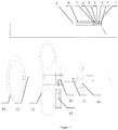
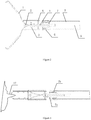
- An open-close-repeatable rotatable hemoclip for the gastrointestinal tract with electrocoagulation includes a clamping assembly, a tightening assembly, an insulating outer tube assembly and a handle assembly.
- the clamping assembly includes two oppositely arranged metal clips 1.
- the insulating outer tube assembly includes an electric cutting wire 8, a guide tube 11 and a spring hose 9.
- a tail portion of the electric cutting wire 8 is arranged inside the guide tube 11.
- An outer wall of the tail portion of the electric cutting wire 8 closely contacts an inner wall of the guide tube 11.
- the electric cutting wire 8 is arranged inside the spring hose 9.
- a front end of the electric cutting wire 8 is connected to a rear end of the connecting rod 4.
- a front end of the spring hose 9 is connected to a rear end of the fixing base 6.
- the handle assembly includes a thumb ring 16, a handle 15, a slide ring 14, a rotary wheel 10, an electrode 13 and an electrode holder 12.
- the thumb ring 16 is arranged at a rear end of the handle 15.
- the slide ring 14 is arranged on the handle 15.
- the rotary wheel 10 is arranged at a front portion of the handle 15.
- the electrode holder 12 is arranged inside the slide ring 14.
- the electrode 13 is arranged inside the electrode holder 12.
- the electrode holder 12 and the electrode 13 are provided with matching threads, and the threads on the electrode 13 are screwed into the electrode holder 12.
- a rear end of the spring hose 9 is connected to a front end of the handle 15.
- the guide tube 11 deeply extends into the handle 15 and the electrode holder 12.
- the guide tube 11 and the rotary wheel 10 are relatively fixed in the radial direction and relatively slidably connected in the axial direction. Also, the guide tube 11 is tightly pressed by the electrode 13.
- the guide tube 11 is driven to rotate with respect to the handle 15 by rotating the rotary wheel 10 so as to realize a rotation of the metal clips 1.
- the slide ring 14 slides back and forth on the handle 15 to drive the guide tube 11 to move back and forth, so as to drive the clamping assembly to reciprocate in the tightening tube 11.
- the metal clips 1 are opened or closed, accordingly. When a predetermined tensile force is exerted, the connecting rod 4 and the movable pin 3 are separated, so as to drive a separation of the releasing piece 7 and the tightening tube 5.
- the tail end of each metal clip 1 is fixed in a preset slot of the tightening tube 5.
- the metal clips 1 are closed and self-locked to realize a release of the metal clips 1.
- the tightening tube 5, the fixing base 6, the spring hose 9, the releasing piece 7, the metal clips 1, the movable pin 3, the connecting rod 4, the electric cutting wire 8 and the guide tube 11 are all made of a metal material.
- An inner wall and an outer wall of the tightening tube 5, an inner wall and an outer wall of the fixing base 6, and an outer wall of the spring hose 9 are all provided with an insulating coating.
- the inner wall and the outer wall of the tightening tube 5 and the fixing base 6 are covered with the insulating coating through a brushing process or a baking process etc.
- the outer wall of the spring hose 9 is plastic-coated with a layer of insulating coating through the plastic coating process.
- the insulating coating includes insulating polymer materials such as polytetrafluoroethylene, fluorinated ethylene-propylene, ethylene-tetrafluoroethylene copolymer, polyvinylidene fluoride or silicone rubber etc.
- the insulating coating can prevent the lower half portion, except for the metal clip 1, from burning tissues by mistake, thereby avoiding or reducing touching other healthy tissues during the electrocoagulation.
- each metal clip 1 is provided with a bent part 1a to avoid a wobble of the clamping assembly.
- a head end 1b of each metal clip 1 has a quarter-spherical shape and is provided with a tooth-shaped part, and tooth-shaped parts of metal clips 1 are engaged with each other.
- a front portion of the metal clip 1 is gradually widened from front to back.
- a curved part 1c is arranged between the front portion and a rear portion of the metal clip 1 to increase the strength of the metal clip 1.
- the rear portion of the metal clip 1 is a large arc, and the strength and elasticity are increased due to the arc structure.
- the rear portion of the metal clip 1 is provided with a hole.
- the metal clip 1 is connected to the movable pin 3 through the hole.
- a front end of the connecting rod 4 is provided with a locking slot 4b, and both sides of the locking slot 4b are provided with a pin hole 4a.
- the locking slot 4b is connected to the movable pin 3 through the pin holes 4a.
- the two metal clips 1 are fixed in the locking slot 4b to ensure a relative fixation when the metal clips 1 are opened repeatedly.
- a lower portion of a front end of the connecting rod 4 is provided with a step 4c.
- a rear end of the connecting rod 4 is provided with a counter bore 4d.
- a front end of the electric cutting wire 8 is connected within the counter bore 4d through welding.
- the overall releasing piece 7 has a cylindrical shape, which can reduce the friction force during the rotation.
- a head end 7a of the releasing piece 7 consists of two projecting steps. The two projecting steps are hung on an opening of the tightening tube 5.
- An axial outer diameter of a front portion of the releasing piece 7 is matched with an inner diameter of the tail portion of the tightening tube 5 to realize a relative fixation in the axial direction and a relative rotary connection in the radial direction.
- a rear portion 7b of the releasing piece 7 is provided with a step shaft, and the step shaft is matched with a step hole in the fixing base 6 to realize the relative fixation in the axial direction and the relative rotary connection in the radial direction to avoid a disengagement toward the head of the metal clip.
- the head end 7a of the releasing piece 7 is driven by the connecting rod 4 to separate from the tightening tube 5.
- the front portion of the releasing piece 7 and the tail portion of the tightening tube 5 are relatively fixed in the axial direction and relatively rotatably connected in the radial direction.
- the rear portion 7b of the releasing piece 7 and the fixing base 6 are relatively fixed in the axial direction and relatively rotatably connected in the radial direction.
- the releasing piece 7 overlaps with the tail portion of the tightening tube 5 and the fixing base 6, to form a combination of which internal parts and external parts cooperate with each other, so as to achieve the function of rotation.
- the overall retention length is reduced to about 12.5mm, so that the retention length inside the human body is shortened.
- one end of the high-frequency cable 19 is inserted into the electrode 13, and the other end of the high-frequency cable is connected to a high-frequency electrotome.
- the lesion region is determined by the marks 18 according to the actual demand of the operation to help the doctor to determine the size of the lesion and the surgical method.
- the voltage is adjusted according to the actual situation to realize a coagulation of blood on the exudation points.
- the bleeding point 17 can be closed by means of the closing function of metal clips 1.
- the function of repeatable opening and closing of the metal clips 1 is realized by pushing and pulling the slide ring 14.
- the bleeding point 17 is pre-clamped, and after the bleeding point 17 is confirmed, the metal clip 1 is released, so that the bleeding point 17 and wound are closed. By doing so, the operation time is shortened, the patients can suffer less and medical costs are reduced.
Landscapes
- Health & Medical Sciences (AREA)
- Surgery (AREA)
- Life Sciences & Earth Sciences (AREA)
- Engineering & Computer Science (AREA)
- Heart & Thoracic Surgery (AREA)
- Veterinary Medicine (AREA)
- Nuclear Medicine, Radiotherapy & Molecular Imaging (AREA)
- Biomedical Technology (AREA)
- Public Health (AREA)
- Medical Informatics (AREA)
- Molecular Biology (AREA)
- Animal Behavior & Ethology (AREA)
- General Health & Medical Sciences (AREA)
- Reproductive Health (AREA)
- Vascular Medicine (AREA)
- Physics & Mathematics (AREA)
- Plasma & Fusion (AREA)
- Otolaryngology (AREA)
- Surgical Instruments (AREA)
Claims (5)
- Ensemble hémoclip rotatif pour le tractus gastro-intestinal à électrocoagulation, comprenant :un ensemble de clampage ;un ensemble de serrage ;un ensemble tube extérieur isolant et un ensemble poignée ;l'ensemble de clampage pouvant tourner, pouvant être ouvert et fermé de manière répétée et étant libérable sous l'action de l'ensemble poignée, de l'ensemble tube extérieur isolant et de l'ensemble de serrage ;l'ensemble de clampage comportant deux agrafes métalliques (1) agencées face à face ;l'ensemble de serrage comportant un tube de serrage (5), une tige intermédiaire (4), une pièce de libération (7) et une base de fixation (6) ;une broche de fixation (2) étant agencée à l'intérieur d'une partie distale du tube de serrage (5) ;deux ouvertures symétriques étant agencées sur une paroi dans une partie proximale du tube de serrage ;une paroi d'une partie distale des deux ouvertures symétriques étant respectivement pré-pourvue d'une fente appariée à une extrémité proximale de chaque agrafe ;dans le tube de serrage (5), des parties proximales des deux agrafes métalliques (1) étant reliées à la tige intermédiaire (4) par le biais d'une broche mobile (3) ;la pièce de libération globale (7) ayant une forme cylindrique ;une partie distale (7a) de la pièce de libération (7) comportant deux étages en saillie ;les deux étages en saillie étant conçus pour venir en prise avec une ouverture du tube de serrage (5) ;un diamètre extérieur axial de la partie distale (7a) de la pièce de libération (7) étant apparié à un diamètre intérieur d'une partie proximale du tube de serrage (5) et la partie distale (7a) de la pièce de libération (7) et la partie proximale du tube de serrage (5) étant conçues pour être fixées l'une par rapport à l'autre dans la direction axiale et étant reliées de manière rotative l'une par rapport à l'autre dans une direction radiale ;une partie proximale (7b) de la pièce de libération (7) étant pourvue d'un arbre étagé ;l'arbre étagé étant apparié à un trou d'étage dans la base de fixation (6) et étant conçu pour fixer la partie proximale (7b) de la pièce de libération (7) par rapport à la base de fixation (6) dans la direction axiale et étant relié de manière rotative par rapport à la base de fixation (6) dans la direction radiale ; et
lorsqu'une force de traction prédéterminée est exercée, la partie distale (7a) de la pièce de libération (7) étant conçue pour être entraînée par la tige intermédiaire (4) pour se séparer du tube de serrage (5) ;une partie distale de la tige intermédiaire (4) étant disposée à l'intérieur du tube de serrage (5) et une partie proximale de la tige intermédiaire (4) étant disposée à l'intérieur de la pièce de libération (7), successivement ;
l'ensemble tube extérieur isolant comportant un tuyau à ressort (9) ;une extrémité distale du tuyau à ressort (9) étant reliée à une extrémité proximale de labase de fixation (6) ;
l'ensemble poignée comportant une bague pour le pouce (16), une poignée (15), une bague coulissante (14) et une roue rotative (10) ;
la bague pour le pouce (16) étant agencée au niveau d'une extrémité proximale de la poignée (15) ;la bague coulissante (14) étant agencée sur la poignée (15) ;la roue rotative (10) étant agencée au niveau d'une extrémité distale de la poignée (15) ;une extrémité proximale du tuyau à ressort (9) étant reliée à l'extrémité distale de la poignée (15) ;les agrafes métalliques (1) étant conçues pour être ouvertes ou fermées lorsque l'ensemble de clampage effectue un mouvement de va-et-vient ;la tige intermédiaire (4) et la broche mobile (3) étant conçues pour être séparées lorsqu'une force de traction prédéterminée est exercée ;une extrémité proximale de chaque agrafe métallique (1) étant située à demeure dans une fente prédéfinie du tube de serrage (5) ;les agrafes métalliques (1) étant conçues pour être fermées et auto-verrouillées pour réaliser une libération des agrafes métalliques (1) ;les extrémités proximales des deux agrafes métalliques (1) agencées face à face étant pourvues d'une partie pliée ;l'extrémité distale de chaque agrafe métallique (1) ayant une forme de quart de sphère ;l'extrémité distale de chaque agrafe métallique (1) étant pourvue d'une partie en forme de dent, et des parties en forme de dent des agrafes métalliques (1) venant en prise l'une avec l'autre ;une partie distale de chaque agrafe métallique (1) étant progressivement élargie d'une direction distale à une direction proximale ;une partie courbe étant agencée entre la partie distale et une partie proximale de chaque agrafe métallique (1) ;la partie proximale de chaque agrafe métallique (1) étant un arc ;la partie proximale de chaque agrafe métallique (1) étant pourvue d'un trou ; etchaque agrafe métallique (1) étant reliée à la broche mobile (3) par le biais du trou ;caractérisé en ce que, l'ensemble tube extérieur isolant comporte en outre un fil de coupe électrique (8) ;le fil de coupe électrique (8) est agencé à l'intérieur du tuyau à ressort (9) ;une partie distale du fil de coupe électrique (8) est reliée à une extrémité proximale de la tige intermédiaire (4) ;et en ce que l'ensemble hémoclip rotatif comprend en outre une électrode (13) et un porte-électrode (12) agencés à l'intérieur de l'ensemble poignée ;l'électrode (13) est connectée électriquement à l'ensemble de clampage par le biais de l'ensemble tube extérieur isolant et de l'ensemble de serrage ;l'ensemble tube extérieur isolant comporte en outre un tube de guidage (11) ;une partie proximale du fil de coupe électrique (8) étant agencée à l'intérieur du tube de guidage (11) ;une paroi extérieure de la partie proximale du fil de coupe électrique (8) étant en contact avec une paroi intérieure du tube de guidage (11) ;le porte-électrode (12) étant agencé à l'intérieur de la bague coulissante (14) ;l'électrode (13) étant agencée à l'intérieur du porte-électrode (12) ;une partie proximale du tube de guidage (11) étant disposée dans la poignée (15) et le porte-électrode (12) ;le tube de guidage (11) et la roue rotative (10) étant fixes l'un par rapport à l'autre dans la direction radiale et le tube de guidage (11) étant conçu pour tourner par rapport à la poignée en faisant tourner la roue rotative (10) ; etle tube de guidage (11) et la roue rotative (10) étant reliés de manière coulissante l'un par rapport à l'autre dans la direction axiale ;le tube de guidage (11) étant fermement pressé par l'électrode (13) ;le tube de guidage (11) étant conçu pour tourner par rapport à la poignée (15) en faisant tourner la roue rotative (10) de manière à réaliser une rotation des agrafes métalliques (1) ;la bague coulissante (14) coulissant d'avant en arrière sur la poignée (15) pour entraîner le tube de guidage (11) à se déplacer d'avant en arrière, de manière à entraîner l'ensemble de clampage pour effectuer un mouvement de va-et-vient dans le tube de serrage (5) ;le tube de serrage (5), la base de fixation (6), le tuyau à ressort (9), la pièce de libération (7), les agrafes métalliques (1), la broche mobile (3), la tige intermédiaire (4), le fil de coupe électrique (8) et le tube de guidage (11) étant constitués d'un matériau métallique ; etune paroi intérieure et une paroi extérieure du tube de serrage (5), une paroi intérieure et une paroi extérieure de la base de fixation (6), et une paroi extérieure du tuyau à ressort (9) étant toutes pourvues d'un revêtement isolant. - Ensemble hémoclip rotatif pour le tractus gastro-intestinal à électrocoagulation selon la revendication 1,
le porte-électrode (12) et l'électrode (13) étant pourvus de fils appariés, et les fils sur l'électrode (13) étant vissés dans le porte-électrode (12). - Ensemble hémoclip rotatif pour le tractus gastro-intestinal à électrocoagulation selon la revendication 1,
une extrémité distale de la tige intermédiaire (4) étant pourvue d'une fente de verrouillage (4b), et les deux côtés de la fente de verrouillage (4b) étant pourvus d'un trou de broche (4a) ;
la fente de verrouillage (4b) étant reliée à la broche mobile (3) par le biais du trou de broche (4a) ;
les deux agrafes métalliques (1) étant fixées dans la fente de verrouillage (4b) ;
une partie distale de l'extrémité distale de la tige intermédiaire (4) étant pourvue d'un étage (4c) ;
l'extrémité proximale de la tige intermédiaire (4) étant pourvue d'un contre-alésage (4d) ; l'extrémité distale du fil de coupe électrique (8) étant reliée à l'intérieur du contre-alésage (4d) ;
le trou de broche (4a) de la tige intermédiaire (4) étant conçu pour être rompu et la tige intermédiaire (4) étant conçue pour être séparée de la broche mobile (3) sous l'effet de la force de traction prédéterminée. - Ensemble hémoclip rotatif pour le tractus gastro-intestinal à électrocoagulation selon la revendication 1,
la paroi intérieure et la paroi extérieure du tube de serrage (5) et la paroi intérieure et la paroi extérieure de la base de fixation (6) étant recouvertes du revêtement isolant par processus de brossage ou par processus de cuisson ; et
la paroi extérieure du tuyau à ressort (9) étant revêtue de plastique avec une couche de revêtement isolant, par processus de revêtement plastique. - Ensemble hémoclip rotatif répétable d'ouverture-fermeture pour le tractus gastro-intestinal à électrocoagulation selon la revendication 4,
le revêtement étant choisi dans le groupe constitué de polytétrafluoroéthylène, d'éthylène-propylène fluoré, d'un copolymère d'éthylène-tétrafluoroéthylène, de fluorure de polyvinylidène et de caoutchouc de silicone.
Applications Claiming Priority (2)
| Application Number | Priority Date | Filing Date | Title |
|---|---|---|---|
| CN201611004337.5A CN106491176A (zh) | 2016-11-15 | 2016-11-15 | 一种可旋转重复开闭止血夹 |
| CN201611004338.XA CN106473805B (zh) | 2016-11-15 | 2016-11-15 | 一种带电凝可重复开合及旋转的消化道止血夹 |
Publications (2)
| Publication Number | Publication Date |
|---|---|
| EP3320863A1 EP3320863A1 (fr) | 2018-05-16 |
| EP3320863B1 true EP3320863B1 (fr) | 2021-03-31 |
Family
ID=60413056
Family Applications (1)
| Application Number | Title | Priority Date | Filing Date |
|---|---|---|---|
| EP17201288.2A Active EP3320863B1 (fr) | 2016-11-15 | 2017-11-13 | Hémoclip rotatif répétable d'ouverture-fermeture pour le tractus gastro-intestinal par électrocoagulation |
Country Status (2)
| Country | Link |
|---|---|
| US (1) | US10610234B2 (fr) |
| EP (1) | EP3320863B1 (fr) |
Families Citing this family (11)
| Publication number | Priority date | Publication date | Assignee | Title |
|---|---|---|---|---|
| CN108969043B (zh) * | 2018-08-17 | 2024-05-28 | 刘建强 | 可释放消化道切口闭合装置 |
| EP3876814A4 (fr) | 2018-11-08 | 2022-08-17 | Cedars-Sinai Medical Center | Nouvel outil pour l'hémostase et le rapprochement tissulaire |
| US12490991B2 (en) | 2020-05-08 | 2025-12-09 | Cedars-Sinai Medical Center | Systems and methods for hemoclip deployment |
| CN111904484B (zh) * | 2020-08-31 | 2024-07-30 | 江苏康宏医疗科技有限公司 | 可旋转重复开闭软组织夹变径圆丝弹簧管 |
| CN114680992B (zh) * | 2020-12-25 | 2025-03-18 | 常州乐奥医疗科技股份有限公司 | 止血夹用的夹头组件及止血夹 |
| CN112826586B (zh) * | 2021-03-10 | 2022-03-22 | 西安医学院第二附属医院 | 一种妇产科手术电凝钳 |
| CN113907870B (zh) * | 2021-11-06 | 2023-08-15 | 嘉兴市中医医院 | 一种止血辅助电凝活检钳 |
| CN114431952B (zh) * | 2022-01-23 | 2023-05-16 | 吉林大学第一医院 | 一种多功能肝胆胰外科临床用止血器 |
| CN115944347B (zh) * | 2023-01-04 | 2026-04-24 | 浙江首鼎医学科技有限公司 | 一种具有分体式结构的止血夹 |
| CN117064537A (zh) * | 2023-08-18 | 2023-11-17 | 浙江创想医学科技有限公司 | 一种旋转钢丝挂钩止血钳及其制作工艺 |
| CN120203702B (zh) * | 2025-05-28 | 2025-08-19 | 四川大学华西医院 | 一种肝脏外科手术用下腔静脉根部血管解剖分离钳 |
Citations (1)
| Publication number | Priority date | Publication date | Assignee | Title |
|---|---|---|---|---|
| CN204909551U (zh) * | 2015-07-28 | 2015-12-30 | 杭州安杰思医学科技有限公司 | 可旋转止血夹 |
Family Cites Families (10)
| Publication number | Priority date | Publication date | Assignee | Title |
|---|---|---|---|---|
| CA2103773C (fr) | 1992-08-19 | 1998-11-03 | David T. Green | Manche pour instruments chirurgicaux endoscopiques et structure de machoires |
| DE4323584A1 (de) * | 1993-07-14 | 1995-01-19 | Delma Elektro Med App | Zerlegbares medizinisches Instrument |
| WO1996014020A1 (fr) | 1994-11-02 | 1996-05-17 | Olympus Optical Co. Ltd. | Instrument fonctionnant avec un endoscope |
| DE19512640C2 (de) * | 1995-04-05 | 1997-01-30 | Winter & Ibe Olympus | Chirurgisches Endoskopinstrument mit HF-Arbeitselektrode |
| JP2000254143A (ja) | 1999-03-08 | 2000-09-19 | Asahi Optical Co Ltd | 内視鏡用止血クリップ装置 |
| WO2001097696A1 (fr) * | 2000-06-19 | 2001-12-27 | Image-Guided Neurologics, Inc. | Systeme et methode de traitement exovasculaire peu invasif d'un anevrisme |
| JP3989170B2 (ja) * | 2000-10-05 | 2007-10-10 | オリンパス株式会社 | 高周波処置具 |
| JP3934458B2 (ja) * | 2002-04-09 | 2007-06-20 | ペンタックス株式会社 | 内視鏡用バイポーラ型高周波止血鉗子 |
| JP4137931B2 (ja) * | 2005-10-28 | 2008-08-20 | オリンパスメディカルシステムズ株式会社 | 内視鏡用処置具 |
| US8585716B2 (en) * | 2006-12-13 | 2013-11-19 | Boston Scientific Scimed, Inc. | Apparatus for applying hemostatic clips |
-
2017
- 2017-11-13 EP EP17201288.2A patent/EP3320863B1/fr active Active
- 2017-11-13 US US15/810,155 patent/US10610234B2/en active Active
Patent Citations (1)
| Publication number | Priority date | Publication date | Assignee | Title |
|---|---|---|---|---|
| CN204909551U (zh) * | 2015-07-28 | 2015-12-30 | 杭州安杰思医学科技有限公司 | 可旋转止血夹 |
Also Published As
| Publication number | Publication date |
|---|---|
| US10610234B2 (en) | 2020-04-07 |
| EP3320863A1 (fr) | 2018-05-16 |
| US20180132855A1 (en) | 2018-05-17 |
Similar Documents
| Publication | Publication Date | Title |
|---|---|---|
| US10610234B2 (en) | Open-close-repeatable rotatable hemoclip for the gastrointestinal tract with electrocoagulation | |
| JP7496158B2 (ja) | 電気手術切除器具 | |
| KR101283717B1 (ko) | 내시경용 처치구 | |
| US11324544B2 (en) | Medical instrument | |
| CN106473805B (zh) | 一种带电凝可重复开合及旋转的消化道止血夹 | |
| JP5563485B2 (ja) | ポリープ除去装置および使用方法 | |
| EP3081174B1 (fr) | Pince hémostatique | |
| AU2019260152B2 (en) | Multifunctional high-frequency electric knife | |
| US20090131933A1 (en) | Bipolar forceps | |
| US20090131932A1 (en) | Bipolar forceps having a cutting element | |
| JPH11192205A (ja) | 内視鏡用ドレナージチューブ留置具 | |
| CN106572883A (zh) | 外科手术器械的电极及使用方法 | |
| CN206443757U (zh) | 一种带电凝可重复开合及旋转的消化道止血夹 | |
| JP2007117405A (ja) | 内視鏡用処置具 | |
| JP7732673B2 (ja) | 電気手術切除器具 | |
| CN108992140A (zh) | 一种多功能内镜下剪状电刀 | |
| JP2003220074A (ja) | 医療装置 | |
| US10548626B2 (en) | Endoscopic tissue manipulation tool | |
| CN109893239A (zh) | 便于组织移除的基于能量的外科装置和系统 | |
| CN121987326A (zh) | 一种多功能穿刺悬吊器械 | |
| HK1261009A1 (en) | A multifunctional high-frequency electrosurgical cutting knife |
Legal Events
| Date | Code | Title | Description |
|---|---|---|---|
| PUAI | Public reference made under article 153(3) epc to a published international application that has entered the european phase |
Free format text: ORIGINAL CODE: 0009012 |
|
| STAA | Information on the status of an ep patent application or granted ep patent |
Free format text: STATUS: REQUEST FOR EXAMINATION WAS MADE |
|
| 17P | Request for examination filed |
Effective date: 20171113 |
|
| AK | Designated contracting states |
Kind code of ref document: A1 Designated state(s): AL AT BE BG CH CY CZ DE DK EE ES FI FR GB GR HR HU IE IS IT LI LT LU LV MC MK MT NL NO PL PT RO RS SE SI SK SM TR |
|
| AX | Request for extension of the european patent |
Extension state: BA ME |
|
| STAA | Information on the status of an ep patent application or granted ep patent |
Free format text: STATUS: EXAMINATION IS IN PROGRESS |
|
| 17Q | First examination report despatched |
Effective date: 20191002 |
|
| GRAP | Despatch of communication of intention to grant a patent |
Free format text: ORIGINAL CODE: EPIDOSNIGR1 |
|
| STAA | Information on the status of an ep patent application or granted ep patent |
Free format text: STATUS: GRANT OF PATENT IS INTENDED |
|
| RIC1 | Information provided on ipc code assigned before grant |
Ipc: A61B 18/00 20060101ALN20201028BHEP Ipc: A61B 17/12 20060101ALN20201028BHEP Ipc: A61B 18/12 20060101ALI20201028BHEP Ipc: A61B 17/122 20060101AFI20201028BHEP Ipc: A61B 17/128 20060101ALI20201028BHEP Ipc: A61B 18/14 20060101ALI20201028BHEP Ipc: A61B 17/00 20060101ALN20201028BHEP |
|
| INTG | Intention to grant announced |
Effective date: 20201125 |
|
| RAP1 | Party data changed (applicant data changed or rights of an application transferred) |
Owner name: ZHEJIANG CHUANGXIANG MEDICAL TECHNOLOGY CO., LTD. |
|
| GRAS | Grant fee paid |
Free format text: ORIGINAL CODE: EPIDOSNIGR3 |
|
| GRAA | (expected) grant |
Free format text: ORIGINAL CODE: 0009210 |
|
| STAA | Information on the status of an ep patent application or granted ep patent |
Free format text: STATUS: THE PATENT HAS BEEN GRANTED |
|
| AK | Designated contracting states |
Kind code of ref document: B1 Designated state(s): AL AT BE BG CH CY CZ DE DK EE ES FI FR GB GR HR HU IE IS IT LI LT LU LV MC MK MT NL NO PL PT RO RS SE SI SK SM TR |
|
| REG | Reference to a national code |
Ref country code: GB Ref legal event code: FG4D Ref country code: CH Ref legal event code: EP |
|
| REG | Reference to a national code |
Ref country code: AT Ref legal event code: REF Ref document number: 1376051 Country of ref document: AT Kind code of ref document: T Effective date: 20210415 |
|
| REG | Reference to a national code |
Ref country code: DE Ref legal event code: R096 Ref document number: 602017035584 Country of ref document: DE |
|
| REG | Reference to a national code |
Ref country code: IE Ref legal event code: FG4D |
|
| REG | Reference to a national code |
Ref country code: LT Ref legal event code: MG9D |
|
| PG25 | Lapsed in a contracting state [announced via postgrant information from national office to epo] |
Ref country code: BG Free format text: LAPSE BECAUSE OF FAILURE TO SUBMIT A TRANSLATION OF THE DESCRIPTION OR TO PAY THE FEE WITHIN THE PRESCRIBED TIME-LIMIT Effective date: 20210630 Ref country code: NO Free format text: LAPSE BECAUSE OF FAILURE TO SUBMIT A TRANSLATION OF THE DESCRIPTION OR TO PAY THE FEE WITHIN THE PRESCRIBED TIME-LIMIT Effective date: 20210630 Ref country code: FI Free format text: LAPSE BECAUSE OF FAILURE TO SUBMIT A TRANSLATION OF THE DESCRIPTION OR TO PAY THE FEE WITHIN THE PRESCRIBED TIME-LIMIT Effective date: 20210331 Ref country code: HR Free format text: LAPSE BECAUSE OF FAILURE TO SUBMIT A TRANSLATION OF THE DESCRIPTION OR TO PAY THE FEE WITHIN THE PRESCRIBED TIME-LIMIT Effective date: 20210331 |
|
| PG25 | Lapsed in a contracting state [announced via postgrant information from national office to epo] |
Ref country code: RS Free format text: LAPSE BECAUSE OF FAILURE TO SUBMIT A TRANSLATION OF THE DESCRIPTION OR TO PAY THE FEE WITHIN THE PRESCRIBED TIME-LIMIT Effective date: 20210331 Ref country code: LV Free format text: LAPSE BECAUSE OF FAILURE TO SUBMIT A TRANSLATION OF THE DESCRIPTION OR TO PAY THE FEE WITHIN THE PRESCRIBED TIME-LIMIT Effective date: 20210331 Ref country code: SE Free format text: LAPSE BECAUSE OF FAILURE TO SUBMIT A TRANSLATION OF THE DESCRIPTION OR TO PAY THE FEE WITHIN THE PRESCRIBED TIME-LIMIT Effective date: 20210331 |
|
| REG | Reference to a national code |
Ref country code: NL Ref legal event code: MP Effective date: 20210331 |
|
| REG | Reference to a national code |
Ref country code: AT Ref legal event code: MK05 Ref document number: 1376051 Country of ref document: AT Kind code of ref document: T Effective date: 20210331 |
|
| PG25 | Lapsed in a contracting state [announced via postgrant information from national office to epo] |
Ref country code: CZ Free format text: LAPSE BECAUSE OF FAILURE TO SUBMIT A TRANSLATION OF THE DESCRIPTION OR TO PAY THE FEE WITHIN THE PRESCRIBED TIME-LIMIT Effective date: 20210331 Ref country code: EE Free format text: LAPSE BECAUSE OF FAILURE TO SUBMIT A TRANSLATION OF THE DESCRIPTION OR TO PAY THE FEE WITHIN THE PRESCRIBED TIME-LIMIT Effective date: 20210331 Ref country code: LT Free format text: LAPSE BECAUSE OF FAILURE TO SUBMIT A TRANSLATION OF THE DESCRIPTION OR TO PAY THE FEE WITHIN THE PRESCRIBED TIME-LIMIT Effective date: 20210331 Ref country code: SM Free format text: LAPSE BECAUSE OF FAILURE TO SUBMIT A TRANSLATION OF THE DESCRIPTION OR TO PAY THE FEE WITHIN THE PRESCRIBED TIME-LIMIT Effective date: 20210331 Ref country code: NL Free format text: LAPSE BECAUSE OF FAILURE TO SUBMIT A TRANSLATION OF THE DESCRIPTION OR TO PAY THE FEE WITHIN THE PRESCRIBED TIME-LIMIT Effective date: 20210331 Ref country code: AT Free format text: LAPSE BECAUSE OF FAILURE TO SUBMIT A TRANSLATION OF THE DESCRIPTION OR TO PAY THE FEE WITHIN THE PRESCRIBED TIME-LIMIT Effective date: 20210331 |
|
| PG25 | Lapsed in a contracting state [announced via postgrant information from national office to epo] |
Ref country code: IS Free format text: LAPSE BECAUSE OF FAILURE TO SUBMIT A TRANSLATION OF THE DESCRIPTION OR TO PAY THE FEE WITHIN THE PRESCRIBED TIME-LIMIT Effective date: 20210731 Ref country code: PT Free format text: LAPSE BECAUSE OF FAILURE TO SUBMIT A TRANSLATION OF THE DESCRIPTION OR TO PAY THE FEE WITHIN THE PRESCRIBED TIME-LIMIT Effective date: 20210802 Ref country code: PL Free format text: LAPSE BECAUSE OF FAILURE TO SUBMIT A TRANSLATION OF THE DESCRIPTION OR TO PAY THE FEE WITHIN THE PRESCRIBED TIME-LIMIT Effective date: 20210331 Ref country code: RO Free format text: LAPSE BECAUSE OF FAILURE TO SUBMIT A TRANSLATION OF THE DESCRIPTION OR TO PAY THE FEE WITHIN THE PRESCRIBED TIME-LIMIT Effective date: 20210331 Ref country code: SK Free format text: LAPSE BECAUSE OF FAILURE TO SUBMIT A TRANSLATION OF THE DESCRIPTION OR TO PAY THE FEE WITHIN THE PRESCRIBED TIME-LIMIT Effective date: 20210331 |
|
| REG | Reference to a national code |
Ref country code: DE Ref legal event code: R097 Ref document number: 602017035584 Country of ref document: DE |
|
| PG25 | Lapsed in a contracting state [announced via postgrant information from national office to epo] |
Ref country code: ES Free format text: LAPSE BECAUSE OF FAILURE TO SUBMIT A TRANSLATION OF THE DESCRIPTION OR TO PAY THE FEE WITHIN THE PRESCRIBED TIME-LIMIT Effective date: 20210331 Ref country code: DK Free format text: LAPSE BECAUSE OF FAILURE TO SUBMIT A TRANSLATION OF THE DESCRIPTION OR TO PAY THE FEE WITHIN THE PRESCRIBED TIME-LIMIT Effective date: 20210331 Ref country code: AL Free format text: LAPSE BECAUSE OF FAILURE TO SUBMIT A TRANSLATION OF THE DESCRIPTION OR TO PAY THE FEE WITHIN THE PRESCRIBED TIME-LIMIT Effective date: 20210331 |
|
| PLBE | No opposition filed within time limit |
Free format text: ORIGINAL CODE: 0009261 |
|
| STAA | Information on the status of an ep patent application or granted ep patent |
Free format text: STATUS: NO OPPOSITION FILED WITHIN TIME LIMIT |
|
| 26N | No opposition filed |
Effective date: 20220104 |
|
| PG25 | Lapsed in a contracting state [announced via postgrant information from national office to epo] |
Ref country code: IS Free format text: LAPSE BECAUSE OF FAILURE TO SUBMIT A TRANSLATION OF THE DESCRIPTION OR TO PAY THE FEE WITHIN THE PRESCRIBED TIME-LIMIT Effective date: 20210731 |
|
| PG25 | Lapsed in a contracting state [announced via postgrant information from national office to epo] |
Ref country code: MC Free format text: LAPSE BECAUSE OF FAILURE TO SUBMIT A TRANSLATION OF THE DESCRIPTION OR TO PAY THE FEE WITHIN THE PRESCRIBED TIME-LIMIT Effective date: 20210331 |
|
| REG | Reference to a national code |
Ref country code: CH Ref legal event code: PL |
|
| PG25 | Lapsed in a contracting state [announced via postgrant information from national office to epo] |
Ref country code: LU Free format text: LAPSE BECAUSE OF NON-PAYMENT OF DUE FEES Effective date: 20211113 Ref country code: IT Free format text: LAPSE BECAUSE OF FAILURE TO SUBMIT A TRANSLATION OF THE DESCRIPTION OR TO PAY THE FEE WITHIN THE PRESCRIBED TIME-LIMIT Effective date: 20210331 Ref country code: BE Free format text: LAPSE BECAUSE OF NON-PAYMENT OF DUE FEES Effective date: 20211130 |
|
| REG | Reference to a national code |
Ref country code: BE Ref legal event code: MM Effective date: 20211130 |
|
| PG25 | Lapsed in a contracting state [announced via postgrant information from national office to epo] |
Ref country code: IE Free format text: LAPSE BECAUSE OF NON-PAYMENT OF DUE FEES Effective date: 20211113 |
|
| PG25 | Lapsed in a contracting state [announced via postgrant information from national office to epo] |
Ref country code: HU Free format text: LAPSE BECAUSE OF FAILURE TO SUBMIT A TRANSLATION OF THE DESCRIPTION OR TO PAY THE FEE WITHIN THE PRESCRIBED TIME-LIMIT; INVALID AB INITIO Effective date: 20171113 |
|
| PG25 | Lapsed in a contracting state [announced via postgrant information from national office to epo] |
Ref country code: CY Free format text: LAPSE BECAUSE OF FAILURE TO SUBMIT A TRANSLATION OF THE DESCRIPTION OR TO PAY THE FEE WITHIN THE PRESCRIBED TIME-LIMIT Effective date: 20210331 |
|
| PG25 | Lapsed in a contracting state [announced via postgrant information from national office to epo] |
Ref country code: LI Free format text: LAPSE BECAUSE OF NON-PAYMENT OF DUE FEES Effective date: 20220701 Ref country code: GR Free format text: LAPSE BECAUSE OF FAILURE TO SUBMIT A TRANSLATION OF THE DESCRIPTION OR TO PAY THE FEE WITHIN THE PRESCRIBED TIME-LIMIT Effective date: 20210331 Ref country code: CH Free format text: LAPSE BECAUSE OF NON-PAYMENT OF DUE FEES Effective date: 20220701 |
|
| PG25 | Lapsed in a contracting state [announced via postgrant information from national office to epo] |
Ref country code: MK Free format text: LAPSE BECAUSE OF FAILURE TO SUBMIT A TRANSLATION OF THE DESCRIPTION OR TO PAY THE FEE WITHIN THE PRESCRIBED TIME-LIMIT Effective date: 20210331 |
|
| PG25 | Lapsed in a contracting state [announced via postgrant information from national office to epo] |
Ref country code: TR Free format text: LAPSE BECAUSE OF FAILURE TO SUBMIT A TRANSLATION OF THE DESCRIPTION OR TO PAY THE FEE WITHIN THE PRESCRIBED TIME-LIMIT Effective date: 20210331 |
|
| PG25 | Lapsed in a contracting state [announced via postgrant information from national office to epo] |
Ref country code: MT Free format text: LAPSE BECAUSE OF FAILURE TO SUBMIT A TRANSLATION OF THE DESCRIPTION OR TO PAY THE FEE WITHIN THE PRESCRIBED TIME-LIMIT Effective date: 20210331 |
|
| PGFP | Annual fee paid to national office [announced via postgrant information from national office to epo] |
Ref country code: DE Payment date: 20251117 Year of fee payment: 9 |
|
| PGFP | Annual fee paid to national office [announced via postgrant information from national office to epo] |
Ref country code: GB Payment date: 20251126 Year of fee payment: 9 |
|
| PGFP | Annual fee paid to national office [announced via postgrant information from national office to epo] |
Ref country code: FR Payment date: 20251127 Year of fee payment: 9 |