EP3320954B1 - System zur erzeugung von trockenem inertgas an bord eines flugzeugs - Google Patents
System zur erzeugung von trockenem inertgas an bord eines flugzeugs Download PDFInfo
- Publication number
- EP3320954B1 EP3320954B1 EP17200886.4A EP17200886A EP3320954B1 EP 3320954 B1 EP3320954 B1 EP 3320954B1 EP 17200886 A EP17200886 A EP 17200886A EP 3320954 B1 EP3320954 B1 EP 3320954B1
- Authority
- EP
- European Patent Office
- Prior art keywords
- oxygen
- gas
- water
- membrane
- heat exchanger
- Prior art date
- Legal status (The legal status is an assumption and is not a legal conclusion. Google has not performed a legal analysis and makes no representation as to the accuracy of the status listed.)
- Active
Links
Images
Classifications
-
- B—PERFORMING OPERATIONS; TRANSPORTING
- B64—AIRCRAFT; AVIATION; COSMONAUTICS
- B64D—EQUIPMENT FOR FITTING IN OR TO AIRCRAFT; FLIGHT SUITS; PARACHUTES; ARRANGEMENT OR MOUNTING OF POWER PLANTS OR PROPULSION TRANSMISSIONS IN AIRCRAFT
- B64D37/00—Arrangements in connection with fuel supply for power plant
- B64D37/32—Safety measures not otherwise provided for, e.g. preventing explosive conditions
-
- A—HUMAN NECESSITIES
- A62—LIFE-SAVING; FIRE-FIGHTING
- A62C—FIRE-FIGHTING
- A62C3/00—Fire prevention, containment or extinguishing specially adapted for particular objects or places
- A62C3/07—Fire prevention, containment or extinguishing specially adapted for particular objects or places in vehicles, e.g. in road vehicles
- A62C3/08—Fire prevention, containment or extinguishing specially adapted for particular objects or places in vehicles, e.g. in road vehicles in aircraft
-
- B—PERFORMING OPERATIONS; TRANSPORTING
- B01—PHYSICAL OR CHEMICAL PROCESSES OR APPARATUS IN GENERAL
- B01D—SEPARATION
- B01D5/00—Condensation of vapours; Recovering volatile solvents by condensation
- B01D5/0003—Condensation of vapours; Recovering volatile solvents by condensation by using heat-exchange surfaces for indirect contact between gases or vapours and the cooling medium
-
- B—PERFORMING OPERATIONS; TRANSPORTING
- B01—PHYSICAL OR CHEMICAL PROCESSES OR APPARATUS IN GENERAL
- B01D—SEPARATION
- B01D5/00—Condensation of vapours; Recovering volatile solvents by condensation
- B01D5/0057—Condensation of vapours; Recovering volatile solvents by condensation in combination with other processes
- B01D5/0075—Condensation of vapours; Recovering volatile solvents by condensation in combination with other processes with heat exchanging
-
- B—PERFORMING OPERATIONS; TRANSPORTING
- B01—PHYSICAL OR CHEMICAL PROCESSES OR APPARATUS IN GENERAL
- B01D—SEPARATION
- B01D53/00—Separation of gases or vapours; Recovering vapours of volatile solvents from gases; Chemical or biological purification of waste gases, e.g. engine exhaust gases, smoke, fumes, flue gases, aerosols
- B01D53/26—Drying gases or vapours
- B01D53/265—Drying gases or vapours by refrigeration (condensation)
-
- B—PERFORMING OPERATIONS; TRANSPORTING
- B01—PHYSICAL OR CHEMICAL PROCESSES OR APPARATUS IN GENERAL
- B01D—SEPARATION
- B01D53/00—Separation of gases or vapours; Recovering vapours of volatile solvents from gases; Chemical or biological purification of waste gases, e.g. engine exhaust gases, smoke, fumes, flue gases, aerosols
- B01D53/26—Drying gases or vapours
- B01D53/266—Drying gases or vapours by filtration
-
- B—PERFORMING OPERATIONS; TRANSPORTING
- B01—PHYSICAL OR CHEMICAL PROCESSES OR APPARATUS IN GENERAL
- B01D—SEPARATION
- B01D53/00—Separation of gases or vapours; Recovering vapours of volatile solvents from gases; Chemical or biological purification of waste gases, e.g. engine exhaust gases, smoke, fumes, flue gases, aerosols
- B01D53/26—Drying gases or vapours
- B01D53/268—Drying gases or vapours by diffusion
-
- B—PERFORMING OPERATIONS; TRANSPORTING
- B01—PHYSICAL OR CHEMICAL PROCESSES OR APPARATUS IN GENERAL
- B01D—SEPARATION
- B01D2258/00—Sources of waste gases
- B01D2258/01—Engine exhaust gases
-
- B—PERFORMING OPERATIONS; TRANSPORTING
- B01—PHYSICAL OR CHEMICAL PROCESSES OR APPARATUS IN GENERAL
- B01D—SEPARATION
- B01D2259/00—Type of treatment
- B01D2259/45—Gas separation or purification devices adapted for specific applications
- B01D2259/4566—Gas separation or purification devices adapted for specific applications for use in transportation means
- B01D2259/4575—Gas separation or purification devices adapted for specific applications for use in transportation means in aeroplanes or space ships
-
- Y—GENERAL TAGGING OF NEW TECHNOLOGICAL DEVELOPMENTS; GENERAL TAGGING OF CROSS-SECTIONAL TECHNOLOGIES SPANNING OVER SEVERAL SECTIONS OF THE IPC; TECHNICAL SUBJECTS COVERED BY FORMER USPC CROSS-REFERENCE ART COLLECTIONS [XRACs] AND DIGESTS
- Y02—TECHNOLOGIES OR APPLICATIONS FOR MITIGATION OR ADAPTATION AGAINST CLIMATE CHANGE
- Y02T—CLIMATE CHANGE MITIGATION TECHNOLOGIES RELATED TO TRANSPORTATION
- Y02T50/00—Aeronautics or air transport
- Y02T50/40—Weight reduction
Definitions
- This disclosure relates to aircraft and aircraft systems, and in particular to an on-board aircraft dried inert gas generation system.
- inerting system decreases the probability of combustion of flammable materials stored in a fuel tank by maintaining a chemically non-reactive or inert gas, such as oxygen-depleted air, in the fuel tank vapor space also known as ullage.
- inert means non-combustible.
- the tank may be made inert by: 1) reducing the oxygen concentration, 2) reducing the fuel concentration of the ullage to below the lower explosive limit (LEL), or 3) increasing the fuel concentration to above the upper explosive limit (UEL).
- LEL lower explosive limit
- UEL upper explosive limit
- Many systems reduce the risk of combustion by reducing the oxygen concentration by introducing an inert gas such as oxygen-depleted air (ODA) to the ullage, thereby displacing oxygen with a mixture of nitrogen and oxygen at target thresholds for avoiding explosion or combustion.
- ODA oxygen-depleted air
- Onboard inert gas systems which supply oxygen-depleted air to the vapor space (i.e., ullage) within the fuel tank.
- the oxygen-depleted air has a substantially reduced oxygen content that reduces or eliminates combustible conditions within the fuel tank.
- Onboard inert gas systems typically use membrane-based gas separators. Such separators contain a membrane that is permeable to oxygen molecules, but relatively impermeable to nitrogen molecules. A pressure differential across the membrane causes oxygen molecules from air on one side of the membrane to pass through the membrane, which forms oxygen-enriched air (OEA) on the low-pressure side of the membrane and ODA on the high-pressure side of the membrane.
- OOA oxygen-enriched air
- aircraft architectures may adopt low-pressure bleed configurations where engine design parameters allow for a bleed flow of compressed air, but at pressures less than the 3,1 bar (45 psi) air (unless stated otherwise, the pressure indications refer to absolute pressure) that has been typically provided in the past to conventional onboard environmental control systems.
- a separate compressor or compressors can be used to provide pressurized air to the membrane gas separator, but this undesirably increases aircraft payload, and also represents another onboard device with moving parts that is subject to maintenance issues or device failure.
- An on-board aircraft inert gas system is defined in claim 1 and comprises a source of hydrocarbon, a source of a gas comprising oxygen, and a first fluid flow path between a gas space in the fuel tank and an inert gas output.
- a reactor is disposed along the first fluid flow path. The reactor comprises an inlet that receives hydrocarbon and the gas comprising oxygen and reacts the hydrocarbon with the oxygen to produce an oxygen-depleted gas comprising water vapor, and an outlet that outputs the oxygen-depleted gas comprising water vapor.
- a first heat exchanger comprises a water-condensing heat rejection side that is disposed along the first fluid flow path.
- the heat rejection side comprises an inlet that receives the oxygen-depleted gas from the reactor and an outlet that outputs oxygen-depleted gas with a reduced water content.
- a heat absorption side of the first heat exchanger is in thermal communication with a heat sink.
- a liquid separator which can be integrated with or separate from the first heat exchanger, separates water condensate produced by the heat rejection side of the first heat exchanger from the oxygen-depleted gas with reduced water content.
- a gas separator comprising a membrane permeable to water comprises a first side of the membrane disposed along the first fluid flow path.
- the separator includes an inlet disposed on the first side of the membrane that receives the oxygen-depleted gas with reduced water content from the first heat exchanger and an outlet that outputs dried oxygen-depleted gas. Water is transported through the membrane to a second side of the membrane, where the separator comprises an outlet that outputs a fluid comprising water.
- a method of generating an inert gas comprises reacting hydrocarbon and oxygen in a gas comprising oxygen to produce an oxygen-depleted gas comprising water vapor. Heat is removed from the oxygen-depleted gas comprising water vapor to condense water vapor in a first heat exchanger, and removing condensate to produce an oxygen-depleted gas having reduced water content. The oxygen-depleted gas having reduced water content is contacted with a membrane permeable to water to produce dried oxygen-depleted gas.
- the reactor can comprise a catalyst that promotes reaction of oxygen with hydrocarbon to produce the oxygen-depleted gas comprising water vapor.
- the heat absorption side of the first heat exchanger comprises an inlet in communication with a source of aircraft ram air.
- the system can further comprise a second heat exchanger comprising a heat rejection side disposed on the first fluid flow path between the reactor and the first heat exchanger, and a heat absorption side in communication with water from the liquid separator.
- the heat absorption side of the second heat exchanger can comprise an inlet that receives liquid water from the liquid separator and an outlet that outputs water vapor.
- the second side of the gas separator can comprise an inlet that receives a gas having a lower partial water vapor pressure than the oxygen-depleted gas with reduced water content.
- the system can comprise a source of aircraft ram air in fluid communication with the gas separator second side inlet.
- the heat absorption side of the first heat exchanger can comprise an inlet in communication with the source of aircraft ram air and an outlet in communication with the gas separator second side inlet.
- the system can further comprise a source of aircraft engine compressed bleed air in fluid communication with the gas separator second side inlet.
- system can further comprise a vacuum pump in communication with the gas separator second side outlet.
- the membrane can comprise molecule size-selective tortuous paths that selectively allow faster transport of water molecules compared to nitrogen or oxygen molecules.
- the membrane can comprise a polymer matrix that provides greater solubility to water molecules than nitrogen or oxygen molecules.
- the source of gas comprising oxygen can comprise a fuel tank gas space
- the source of hydrocarbon comprises the fuel tank gas space
- a fuel tank vapor comprising the hydrocarbon can be reacted with oxygen in the fuel tank vapor in the presence of a catalyst that promotes reaction of oxygen with hydrocarbon to produce the oxygen-depleted gas comprising water vapor.
- water vapor from the oxygen-depleted gas comprising water vapor can be condensed in a heat exchanger cooled by a source of aircraft ram air.
- the oxygen-depleted gas having reduced water content can have a water content of at least 2 g per kg of the oxygen-depleted gas.
- the oxygen-depleted gas having reduced water content can be contacted with a first side of the membrane permeable to water, and a second side of the membrane can be contacted with a gas having a lower partial water vapor pressure than the oxygen-depleted gas with reduced water content.
- aircraft includes any powered conveyance device capable of sustaining flight.
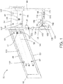
- FIG. 1 is a schematic depiction of an onboard inert aircraft gas system.
- a left wing vent box 46 is disposed along with wing fuel tank 48 in a wing 50 of an aircraft 52.
- the aircraft 52 depicted in a partial view in FIG.
- 1 also includes a center tank 54 disposed in fuselage 56, and also a right wing and tank and vent box (not shown), with the fuel tanks sharing a common vent system 58 that includes left wing climb vent 60, a left wing dive vent 62, center tank climb vent 64, center tank dive vent 66, and other unnumbered vents depicted by the same circular shapes as the numbered vents.
- a common vent system 58 that includes left wing climb vent 60, a left wing dive vent 62, center tank climb vent 64, center tank dive vent 66, and other unnumbered vents depicted by the same circular shapes as the numbered vents.
- a reactor 132 receives a fluid flow 134 (assisted by ullage blower 135) from ullage gas collection vents 137 and ullage gas collection conduits 139.
- the ullage gas contains air components (oxygen and nitrogen) and fuel vapor and serves as both the source of gas comprising oxygen and the source of hydrocarbon.
- other sources of gas comprising oxygen can be utilized (e.g., outside air), and other sources of hydrocarbon can be used (e.g., liquid fuel).
- the gas comprising oxygen should also comprise at least one other component (e.g., nitrogen from air) to form part of the oxygen-depleted gas after the reaction.
- the reactor can be any type of reactor capable of reacting oxygen with hydrocarbon fuel such as in a combustion reaction. Combustion can be carried out with or without a catalyst. Examples of catalytic reactors and associated equipment are disclosed, for example, in published patent application US 2011/0262309A1 .
- the reaction produces an oxygen-depleted stream 138 comprising water and CO 2 as well as residual hydrocarbon, and residual air components (e.g., nitrogen and a reduced amount of oxygen). Combustion can be contained to the reactor 132 with the assistance of flame arrestors 141.
- the oxygen-depleted stream 138 is fed first to a heat rejection side of heat exchanger condenser 142 where it is cooled to condense water vapor in the oxygen-depleted stream 138, producing an oxygen-depleted stream with reduced water content 139.
- Heat exchanger condenser 142 also has a heat absorption side in thermal communication with a heat sink.
- the heat sink (i.e., cold source) can be any type of heat sink, including but not limited to ambient air (e.g., fan-assisted blown air), ram air, conditioned air from an on-board ECS air cycle machine, a heat transfer fluid in communication with a heat absorption side of a heat exchanger in an on-board ECS air cycle machine, a heat transfer fluid in communication with a heat absorption side of a heat exchanger in an on-board ECS vapor cycle machine, a heat transfer fluid in communication with an evaporator of a vapor compression refrigerant loop, or liquid fuel in an on-board fuel tank.
- ambient air e.g., fan-assisted blown air
- ram air conditioned air from an on-board ECS air cycle machine
- a heat transfer fluid in communication with a heat absorption side of a heat exchanger in an on-board ECS air cycle machine a heat transfer fluid in communication with a heat absorption side of a heat exchanger in an on-board ECS
- the heat exchanger condenser 142 is depicted as including an integrated liquid water separator or collector (not shown) for collection of condensate 131.
- a liquid water separator can be disposed downstream of the heat exchanger condenser 142 to separate and remove liquid water from the oxygen-depleted stream 139.
- Condensate 131 can be dumped overboard or used in another process (e.g., to provide evaporative cooling in an aircraft ECS).
- the cooling capacity of the heat exchanger condenser 142 may be insufficient to remove enough water from the oxygen-depleted gas to supply to a fuel tank ullage.
- the combustion reaction with jet fuel produces a relatively large amount of water, yielding roughly 13 molecules of water for every molecule of jet fuel (based on Jet-A surrogate dodecane).
- a condenser can reduce water vapor content only to the dew point of the oxygen-depleted gas at the condenser's operating temperature. At lower altitudes such as below 3048 m (10000 feet) or on the ground, the temperature of available ram air can be above the temperatures needed to remove all of the water in the oxygen-depleted gas.
- the water vapor level of the oxygen-depleted stream 139 exiting from the heat exchanger condenser 142 contains at least 23 g/m 3 of water vapor.
- the water vapor level of the oxygen-depleted stream 139 exiting from the heat exchanger condenser 142 contains at least 19 g per kg of the oxygen-depleted stream 139 (i.e., the oxygen-depleted stream 139 comprises at least 1.9 wt.% water vapor). In some embodiments, the water vapor level of the oxygen-depleted stream 139 exiting from the heat exchanger condenser 142 contains at least 2 g water vapor per kilogram of the oxygen-depleted stream 139 (i.e., the oxygen-depleted stream 139 comprises at least 0.2 wt.% water vapor). In some embodiments, the condenser is cooled with outside air of at least 25°C during one or more operational states.
- the heat exchanger 142 can be sized to maintain a low payload footprint or low demand on ram air such that it does not remove all water even at altitude when ram air is at its coldest.
- Introduction of water into the fuel tanks can cause a number of issues, including condensation inside the tanks which can lead to problems with bacteria growth, ice crystal formation, and fuel quality degradation. Water issues particularly affect while descending from cruise when humid air rushes in and can condense in cold fuel tanks.
- the oxygen-depleted stream 139 exiting from the heat rejection side of heat exchanger condenser 142 has a reduced water content, but as discussed above all water has not necessarily been removed.
- the oxygen-depleted stream 139 is fed to a first side of a gas separator 118 comprising a water-permeable membrane 119.
- the first fluid flow path continues along a first side of the membrane 119 to an inert gas vent line 40 that is in communication with one or more components that utilizes inert gas such as the fuel tank ullage for fuel tank 48 or other fuel tanks, or other inert gas-utilizing components such as a fire suppression system.
- the membrane 119 in different modes of operation, selectively transports water vapor.
- gas separation membranes can rely on one or more physical phenomena for selectivity in transportation of gases across the membrane.
- a selective membrane can rely on size-selective pathways through the membrane that selectively allows transport of smaller molecules over larger molecules. Examples of such membranes include membranes that selectively allow faster transport of smaller water molecules compared to larger nitrogen and oxygen molecules in air.
- Such membranes typically rely on molecule size-selective tortuous paths through a non-porous polymer matrix in the form of a thin film deposited onto a microporous layer.
- the condensability of a molecule is another parameter that can be used in membrane-based gas separations: the more condensable molecule is selectively permeated over the less condensable molecule(s) due to its higher solubility in the polymer matrix, which in turn leads to a larger driving force for permeation.
- selective permeation of water can be accomplished with essentially any polymer-based membrane.
- selective materials for water include polyimides known for use in dehydration applications or 2,2-bistrifluoromethyl-4,5-difluoro-1,3-dioxole/tetrafluoroethylene, silicone rubbers (polydimethyl siloxane, polyoctylmethyl siloxane), polysulfones, polyethers (e.g., a copolymer of poly(ethylene oxide) (PEO) and poly(butylene therephthalate) (PBT), polycarbonates, poly(4-methyl-2-pentyne), poly-trimethyl-silyl-propyne (PTMSP), etc..
- PEO poly(ethylene oxide)
- PBT poly(butylene therephthalate)
- PTMSP poly-trimethyl-silyl-propyne
- the gas selective membrane can include any of the above materials, alone or in combination with each other or other selective materials. Combinations of different materials can be integrated into a single membrane structure (e.g., in layers, or zones in the x-y plane of a membrane structure), or can be disposed in series or in parallel as separate membrane structures or modules.
- any of the aforementioned polymers can selectively permeate water vapor over oxygen and nitrogen, maximizing the membrane's selectivity towards water will minimize the loss of feed air through the membrane during operation when vacuum is the driving force; hence, proper identification of a membrane layer is an important consideration in the case of the membrane dryer connected to a vacuum pump.
- Examples of polymer membranes in this case that can be used with a vacuum pump (or without a vacuum pump) include polyimides, polycarbonates and polysulfones.
- water 148 can be selectively transported across the membrane 119 to a second fluid flow path disposed on a second side of the membrane 119 with a discharge 121 of a fluid comprising water.
- fluid e.g., permeate gas
- flow along the second fluid flow path is provided by heated ram air 146 exhausted from the heat absorption side of the heat exchanger condenser 142.
- the heating of the ram air by the heat exchanger condenser 142 can reduce the relative humidity of the ram air to promote absorption of moisture by the ram air as a sweep gas for the gas separator 118.
- Dried inert air exiting from the gas separator 118 is directed through inert gas vent lines 40 to fuel tank inert gas vents 42.
- the inert gas flow can be aided by a blower (not shown).
- the embodiment depicted in FIG. 1 can accomplish the dual purpose of cooling and drying the combusted inert gas stream, resulting in a much dryer stream entering the fuel tank. Even if outside air is saturated with water vapor, heating it by cooling the inert gas stream raises the temperature such that the air can absorb more water vapor as a sweep gas in the gas separator 118.
- the additional weight of the membrane can in some embodiments be offset by a smaller size of the ram air heat exchanger because of reduced need for temperature reduction of the catalyst exhaust stream since moisture not condensed in the condenser 142 can be removed by the gas separator 118.
- the heated ram air 146 is maintained at or below 80°C (176°F) to accommodate fuel tank specifications.
- 80°C 176°F
- Such an upper limit for the temperature of the inert gas entering an aircraft fuel tank is well within the limits of certain dehydration membranes such as polyimides or polysulfones. The membrane acts as a heat exchanger, so the outside air should not heat up the inert gas beyond this threshold.
- the heated ram air 146 is maintained at or below a temperature of 80°C because inert gas temperatures higher than this may cause evaporation of some lighter fuel fractions leading to an increased load on the reactor 132 and the rest of the inert gas system.
- FIG. 1 is illustrative of a particular example embodiment, and other example embodiments are also contemplated.
- the condensate 131 is shown as exiting the system, e.g., discharged overboard.
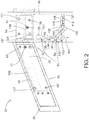
- FIG. 2 is a schematic depiction where the condensate 131 is utilized in the inert gas system. As shown in FIG. 2 , condensate 131 is utilized on a heat absorption side of a second heat exchanger 150 having a heat rejection side disposed on the first flow path between the reactor 132 and the first heat exchanger 142.
- the heat of reaction from the reactor 132 is sufficient to boil or otherwise vaporize condensate 131, thereby absorbing heat from oxygen-depleted gas 138. In some embodiments, this can reduce the heat load on or increase the effectiveness of the first heat exchanger condenser. Since the collection of ram air places an aerodynamic drag on the aircraft resulting in increased fuel consumption, reduced heat load on the heat exchanger condenser 142 can allow for reduced ram air consumption and its accompanying fuel penalty. No condensate collection from the second heat exchanger 150 is shown in FIG. 2 based on an example embodiment where the second heat exchanger 150 does not reduce the temperature of the oxygen-depleted gas below its dew point. In other embodiments, any condensate from the oxygen-depleted gas 138 could be separated and collected with a liquid separator integrated into the second heat exchanger 150 or a separate liquid separator downstream from the second heat exchanger.
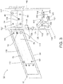
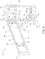
- FIGS. 3 and 4 show additional alternative configurations.
- the water vapor permeating the membrane 119 is collected by a vacuum pump.
- insulation or heating tape can be used along the conduits for the fluid discharge 121 to prevent the permeated water vapor from condensing and freezing before reaching the vent when the system operates at altitudes where the outside temperature is below freezing.
- FIG. 4 depicts an example embodiment where compressed bleed air 154 from an aircraft engine is used as sweep gas for second side of the gas separator 118.
- ram air 144 is dedicated for cooling of the catalyst exhaust stream, and heated ram air 146 can be used in another on-board process or discharged overboard.
- a controller 35 can be in operative communication with the above-referenced components and any associated valves, pumps, compressors, conduits, or other fluid flow components, and with switches, inverters, regulators, sensors, and other electrical system components, and any other system components to selectively operate the inert gas system. These control connections can be through wired electrical signal connections (not shown) or through wireless connections. In some embodiments, the controller 35 can be configured to operate the system according to specified parameters, as discussed in greater detail further below.
- the system can be controlled to set fluid flow rates to produce varying amounts of ODA in response to system parameters.
- system parameters can include, but are not limited to the humidity of the ODA, temperature of the fuel in the vehicle fuel tank(s), oxygen content of the fuel in the fuel tanks, oxygen content of vapor in the ullage of fuel tanks, temperature rise in an enclosed space such as a cargo hold or avionics bay, smoke and/or flame detection in said enclosed spaces, and temperature and/or pressure of vapor in the ullage of fuel tanks, and other on-board parameters such as temperature, oxygen content, and/or humidity level of ullage air.
- the inert gas management system and components thereof such as shown in FIGS.
- 1-4 can include sensors for measuring any of the above-mentioned fluid flow rates, temperatures, oxygen levels, humidity levels, as well as controllable output fans or blowers, or controllable fluid flow control valves or gates. These sensors and controllable devices can be operatively connected to the controller 35, which can be an independent controller dedicated to controlling the inert gas management system, or can interact with other onboard system controllers or with a master controller. In some embodiments, data provided by the controller of the inert gas management system can come directly from a master controller.
Landscapes
- Chemical & Material Sciences (AREA)
- Chemical Kinetics & Catalysis (AREA)
- Engineering & Computer Science (AREA)
- Analytical Chemistry (AREA)
- General Chemical & Material Sciences (AREA)
- Oil, Petroleum & Natural Gas (AREA)
- Aviation & Aerospace Engineering (AREA)
- Health & Medical Sciences (AREA)
- Public Health (AREA)
- Business, Economics & Management (AREA)
- Emergency Management (AREA)
- Physics & Mathematics (AREA)
- Thermal Sciences (AREA)
- Separation Using Semi-Permeable Membranes (AREA)
Claims (14)
- Inertgassystem an Bord eines Flugzeugs, umfassend:eine Kohlenwasserstoffquelle;eine Sauerstoff umfassende Gasquelle;einen ersten Fluidströmungspfad zwischen der Sauerstoff umfassenden Gasquelle und einem Inertgasausgang;einen Reaktor (132), der entlang des ersten Fluidströmungspfads angeordnet ist, umfassend einen Einlass, der Kohlenwasserstoff und das Sauerstoff umfassende Gas aufnimmt und den Kohlenwasserstoff mit dem Sauerstoff umsetzt, um ein Wasserdampf umfassendes sauerstoffarmes Gas zu erzeugen, und einen Auslass, der das Wasserdampf umfassende sauerstoffarme Gas ausstößt;einen ersten Wärmetauscher (142), umfassend eine wasserkondensierende Wärmeabstoßungsseite (142), die entlang des ersten Fluidströmungspfads angeordnet ist, umfassend einen Einlass, der das sauerstoffarme Gas von dem Reaktor aufnimmt, und einen Auslass, der sauerstoffarmes Gas mit einem reduzierten Wassergehalt ausstößt, und eine Wärmeabsorptionsseite in Wärmekommunikation mit einem Kühlkörper;einen Flüssigkeitsabscheider, der Wasserkondensat, das durch die Wärmeabstoßungsseite des ersten Wärmetauschers (142) erzeugt wird, von dem sauerstoffarmen Gas mit reduziertem Wassergehalt trennt; undeinen Gasabscheider (118), umfassend eine Membran (119), die wasserdurchlässig ist, umfassend eine erste Seite der Membran (119), die entlang des ersten Fluidströmungspfads angeordnet ist, wobei der Abscheider einen Einlass an der ersten Seite der Membran (119), der das sauerstoffarme Gas mit reduziertem Wassergehalt von dem ersten Wärmetauscher (142) aufnimmt, und einen Auslass an der ersten Seite der Membran (119), der trockenes sauerstoffarmes Gas ausstößt, umfasst, und eine zweite Seite, die Wasser durch die Membran (119) von dem sauerstoffarmen Gas mit reduziertem Wassergehalt aufnimmt, wobei der Abscheider einen Auslass an der zweiten Seite der Membran (119) umfasst, der ein Fluid ausstößt, das Wasser umfasst;und wobei die Wärmeabsorptionsseite des ersten Wärmetauschers (142) einen Einlass in Kommunikation mit einer Flugzeugstauluftquelle umfasst.
- System nach Anspruch 1, wobei der Reaktor (132) einen Katalysator umfasst, der Umsetzung von Sauerstoff mit Kohlenwasserstoff fördert, um das Wasserdampf umfassende sauerstoffarme Gas zu erzeugen.
- System nach einem der vorhergehenden Ansprüche, ferner umfassend einen zweiten Wärmetauscher, umfassend eine Wärmeabstoßungsseite, die an dem ersten Fluidströmungspfad zwischen dem Reaktor und dem ersten Wärmetauscher (142) angeordnet ist, und eine Wärmeabsorptionsseite in Kommunikation mit Wasser aus dem Flüssigkeitsabscheider.
- System nach Anspruch 3, wobei die Wärmeabsorptionsseite des zweiten Wärmetauschers einen Einlass, der flüssiges Wasser aus dem Flüssigkeitsabscheider aufnimmt, und einen Auslass, der Wasserdampf ausstößt, umfasst.
- System nach einem der vorhergehenden Ansprüche, wobei die zweite Seite des Gasabscheiders einen Einlass umfasst, der ein Gas mit einem niedrigeren partiellen Wasserdampfdruck als das sauerstoffarme Gas mit reduziertem Wassergehalt aufnimmt.
- System nach Anspruch 5, ferner umfassend eine Flugzeugstauluftquelle in Fluidkommunikation mit dem Einlass an der zweiten Seite des Gasabscheiders.
- System nach Anspruch 6, wobei die Wärmeabsorptionsseite des ersten Wärmetauschers (142) einen Einlass in Kommunikation mit der Flugzeugstauluftquelle und einen Auslass in Kommunikation mit dem Einlass an der zweiten Seite des Gasabscheiders umfasst.
- System nach Anspruch 5, ferner umfassend eine Quelle von durch eine Flugzeugturbine komprimierter Zapfluft in Fluidkommunikation mit dem Einlass an der zweiten Seite des Gasabscheiders.
- System nach einem der vorhergehenden Ansprüche, ferner umfassend eine Vakuumpumpe in Kommunikation mit dem Auslass an der zweiten Seite des Gasabscheiders.
- System nach einem der vorhergehenden Ansprüche, wobei die Membran (119) molekülgrößenselektive gewundene Pfade umfasst, die im Vergleich zu Stickstoff- oder Sauerstoffmolekülen selektiv einen schnelleren Transport von Wassermolekülen ermöglichen.
- System nach einem der vorhergehenden Ansprüche, wobei die Membran (119) eine Polymermatrix umfasst, die im Vergleich zu Stickstoff- oder Sauerstoffmolekülen eine höhere Löslichkeit für Wassermoleküle bereitstellt.
- System nach einem der vorhergehenden Ansprüche, wobei die Sauerstoff umfassende Gasquelle einen Kraftstofftankgasraum umfasst und die Kohlenwasserstoffquelle den Kraftstofftankgasraum umfasst.
- Verfahren zum Herstellen eines Inertgases, umfassend:Umsetzen von Kohlenwasserstoff und Sauerstoff in einem Sauerstoff umfassenden Gas, um ein Wasserdampf umfassendes sauerstoffarmes Gas zu erzeugen;Entfernen von Wärme aus dem Wasserdampf umfassenden sauerstoffarmen Gas, um Wasserdampf in einem ersten Wärmetauscher (142) zu kondensieren, und Entfernen von Kondensat, um ein sauerstoffarmes Gas mit reduziertem Wassergehalt zu erzeugen; undInkontaktbringen des sauerstoffarmen Gases mit reduziertem Wassergehalt mit einer Membran (119), die wasserdurchlässig ist, und Entfernen von Wasser durch die Membran (119), um das Inertgas, das trockenes sauerstoffarmes Gas umfasst, zu erzeugen,wobei der erste Wärmetauscher (142) eine wasserkondensierende Wärmeabstoßungsseite (142) umfasst, die entlang eines ersten Fluidströmungspfads angeordnet ist, umfassend einen Einlass, der das sauerstoffarme Gas von dem Reaktor aufnimmt, und einen Auslass, der das sauerstoffarme Gas mit einem reduzierten Wassergehalt ausstößt, und eine Wärmeabsorptionsseite in Wärmekommunikation mit einem Kühlkörper;und wobei die Wärmeabsorptionsseite des ersten Wärmetauschers (142) einen Einlass in Kommunikation mit einer Flugzeugstauluftquelle umfasst.
- Verfahren nach Anspruch 13, umfassend Inkontaktbringen des sauerstoffarmen Gases mit reduziertem Wassergehalt mit einer ersten Seite der Membran (119), die wasserdurchlässig ist, und Inkontaktbringen einer zweiten Seite der Membran (119) mit einem Gas mit einem niedrigeren partiellen Wasserdampfdruck als das sauerstoffarme Gas mit reduziertem Wassergehalt.
Applications Claiming Priority (1)
| Application Number | Priority Date | Filing Date | Title |
|---|---|---|---|
| US15/348,287 US10150571B2 (en) | 2016-11-10 | 2016-11-10 | On-board aircraft reactive inerting dried gas system |
Publications (2)
| Publication Number | Publication Date |
|---|---|
| EP3320954A1 EP3320954A1 (de) | 2018-05-16 |
| EP3320954B1 true EP3320954B1 (de) | 2020-02-26 |
Family
ID=60327084
Family Applications (1)
| Application Number | Title | Priority Date | Filing Date |
|---|---|---|---|
| EP17200886.4A Active EP3320954B1 (de) | 2016-11-10 | 2017-11-09 | System zur erzeugung von trockenem inertgas an bord eines flugzeugs |
Country Status (2)
| Country | Link |
|---|---|
| US (1) | US10150571B2 (de) |
| EP (1) | EP3320954B1 (de) |
Families Citing this family (12)
| Publication number | Priority date | Publication date | Assignee | Title |
|---|---|---|---|---|
| US10312536B2 (en) | 2016-05-10 | 2019-06-04 | Hamilton Sundstrand Corporation | On-board aircraft electrochemical system |
| US10427800B2 (en) | 2016-10-31 | 2019-10-01 | Hamilton Sundstrand Corporation | Air separation system for fuel stabilization |
| US11041424B2 (en) * | 2018-03-21 | 2021-06-22 | Ford Global Technologies, Llc | Method and system for operating a gaseous fuel vehicle |
| US11260346B2 (en) * | 2018-06-25 | 2022-03-01 | Hamilton Sundstrand Corporation | Inerting system |
| US10967326B2 (en) | 2018-09-11 | 2021-04-06 | Hamilton Sundstrand Corporation | Electrochemical drying of humid inert gas for fuel tank inerting |
| US11679893B2 (en) | 2018-10-02 | 2023-06-20 | Hamilton Sundstrand Corporation | Pressurized inerting system |
| US11518501B2 (en) | 2019-01-28 | 2022-12-06 | Goodrich Corporation | System and method for reducing oxidation of friction disks |
| US11125294B2 (en) | 2019-03-22 | 2021-09-21 | Goodrich Corporation | Systems and methods for reducing oxidation of friction disks |
| CN110787395A (zh) * | 2019-09-20 | 2020-02-14 | 安徽延达智能科技有限公司 | 一种机器人用风力灭火系统 |
| US11713132B2 (en) * | 2019-10-04 | 2023-08-01 | Hamilton Sundstrand Corporation | Fuel tank inerting system and method |
| US11486338B2 (en) * | 2019-11-27 | 2022-11-01 | Hamilton Sundstrand Corporation | Aircraft cabin air outflow temperature control for downstream operations |
| US12050039B1 (en) * | 2021-04-20 | 2024-07-30 | United States Of America As Represented By The Secretary Of The Air Force | Aircraft membrane dehydration cooling architecture |
Family Cites Families (103)
| Publication number | Priority date | Publication date | Assignee | Title |
|---|---|---|---|---|
| US2845383A (en) | 1954-12-31 | 1958-07-29 | California Research Corp | Method for controlling atmospheric pollution |
| US3672180A (en) | 1968-02-19 | 1972-06-27 | Edwin R Davis | Fuel vapor recovery apparatus |
| US3590559A (en) | 1968-03-06 | 1971-07-06 | Parker Hannifin Corp | Fuel tank inerting system |
| US3710549A (en) | 1971-01-29 | 1973-01-16 | Parker Hannifin Corp | Fuel tank inerting system |
| US3732668A (en) | 1971-02-24 | 1973-05-15 | Parker Hannifin Corp | Fuel tank inerting system |
| US3847298A (en) | 1972-03-20 | 1974-11-12 | Garrett Corp | Fuel tank inerting system |
| US3788039A (en) | 1972-08-24 | 1974-01-29 | Parker Hannifin Corp | Fuel tank inerting system with means to improve thermal stability of fuel |
| GB1395691A (en) | 1973-10-05 | 1975-05-29 | Garrett Corp | Fuel tank inerting system |
| US4681602A (en) | 1984-12-24 | 1987-07-21 | The Boeing Company | Integrated system for generating inert gas and breathing gas on aircraft |
| US5220799A (en) | 1991-12-09 | 1993-06-22 | Geert Lievens | Gasoline vapor recovery |
| DE4225170A1 (de) | 1992-07-30 | 1994-02-03 | Preussag Anlagenbau | Tankanlage und Verfahren zum Betrieb einer Tankanlage mit einem Tank zur Lagerung von brennbaren Flüssigkeiten |
| US5255735A (en) | 1992-12-21 | 1993-10-26 | Ford Motor Company | Fuel vapor recovery device |
| US5843212A (en) | 1995-05-12 | 1998-12-01 | Gilbarco Inc. | Fuel tank ullage pressure reduction |
| WO1996035634A1 (en) | 1995-05-12 | 1996-11-14 | Gilbarco Inc. | Apparatus and method for reducing the pressure in a volatile organic chemical tank ullage |
| US6440317B1 (en) | 1996-03-18 | 2002-08-27 | Fuel Dynamics | Cyclonic ice separation for low temperature jet fuels |
| US5782188A (en) | 1996-09-25 | 1998-07-21 | Evans; Marvin | Pyrolytic combustion apparatus and method |
| US5918679A (en) | 1997-10-14 | 1999-07-06 | Cramer; Frank B. | Fire safety system |
| US8245978B1 (en) | 1998-06-30 | 2012-08-21 | L'air Liquide Societe Anonyme Pour L'etude Et L'exploitation Des Procedes Georges Claude | Multiple ASM OBIGGS with different permeability and selectivity membranes |
| DE10014792A1 (de) | 1999-06-17 | 2001-01-18 | Daimler Chrysler Ag | Vorrichtung und Verfahren zur Gastrocknung |
| US6315815B1 (en) | 1999-12-16 | 2001-11-13 | United Technologies Corporation | Membrane based fuel deoxygenator |
| JP4892770B2 (ja) | 1999-12-28 | 2012-03-07 | ダイキン工業株式会社 | 燃料電池用加湿装置 |
| US6572679B2 (en) | 2000-05-19 | 2003-06-03 | Membrane Technology And Research, Inc. | Gas separation using organic-vapor-resistant membranes in conjunction with organic-vapor-selective membranes |
| US6578639B1 (en) | 2000-09-01 | 2003-06-17 | Joshua Oghenogieme Osime | Disabler and storage system for hazardous substances |
| US6705092B1 (en) * | 2001-11-14 | 2004-03-16 | Honeywell International Inc. | Vapor membrane dehumidification for air cycle environment control system |
| WO2003076329A1 (en) | 2002-03-05 | 2003-09-18 | Veeder-Root Company Inc. | Apparatus and method to control excess pressure in fuel storage containment system at fuel dispensing facilities |
| US6786207B2 (en) | 2002-04-17 | 2004-09-07 | Toyota Jidosha Kabushiki Kaisha | Evaporative fuel emission control system |
| US6729359B2 (en) * | 2002-06-28 | 2004-05-04 | Shaw Aero Devices, Inc. | Modular on-board inert gas generating system |
| US6997013B2 (en) | 2003-03-07 | 2006-02-14 | Shaw Aero Devices, Inc | Cooling system for an on-board inert gas generating system |
| US7364810B2 (en) | 2003-09-03 | 2008-04-29 | Bloom Energy Corporation | Combined energy storage and fuel generation with reversible fuel cells |
| US8763712B2 (en) | 2003-04-09 | 2014-07-01 | Firepass Corporation | Hypoxic aircraft fire prevention system with advanced hypoxic generator |
| US7204868B2 (en) * | 2004-03-30 | 2007-04-17 | The Boeing Company | Method and apparatus for generating an inert gas on a vehicle |
| US20060011063A1 (en) | 2004-07-16 | 2006-01-19 | Honeywell International Inc. | High temperature gas separation membrane suitable for OBIGGS applications |
| US7459081B2 (en) | 2004-11-30 | 2008-12-02 | Phyre Technologies, Inc. | Contacting systems and methods and uses thereof |
| US7595019B2 (en) | 2005-03-01 | 2009-09-29 | Air Products And Chemicals, Inc. | Method of making an ion transport membrane oxygen separation device |
| JP2009501680A (ja) | 2005-07-08 | 2009-01-22 | ファイア テクノロジーズ、インコーポレイテッド | 触媒反応成分低減システムおよびその使用法 |
| US7481869B2 (en) * | 2005-08-17 | 2009-01-27 | Andrew Llc | Dry gas production systems for pressurizing a space and methods of operating such systems to produce a dry gas stream |
| DE102005053692B3 (de) | 2005-11-10 | 2007-01-11 | Airbus Deutschland Gmbh | Brandschutz mit Brennstoffzellenabluft |
| RU2410143C2 (ru) | 2005-11-10 | 2011-01-27 | Эйрбас Дойчланд Гмбх | Система и способ пожаротушения |
| US7517388B2 (en) | 2006-05-15 | 2009-04-14 | Generon Igs, Inc. | Air separation membrane module with variable sweep stream |
| US8394552B2 (en) | 2006-09-19 | 2013-03-12 | Hamilton Sundstrand Corporation | Jet fuel based high pressure solid oxide fuel cell system |
| US7628965B2 (en) | 2006-11-03 | 2009-12-08 | Honeywell International Inc | Advanced carbon dioxide fuel tank inerting system with desulfurization |
| GB0622565D0 (en) | 2006-11-13 | 2006-12-20 | Airbus Uk Ltd | Water scavenging system |
| US7905259B2 (en) | 2006-11-15 | 2011-03-15 | Honeywell International Inc. | Advanced carbon dioxide fuel tank inerting system |
| US8088196B2 (en) * | 2007-01-23 | 2012-01-03 | Air Products And Chemicals, Inc. | Purification of carbon dioxide |
| WO2009026374A1 (en) | 2007-08-23 | 2009-02-26 | Phyre Technologies Inc. | Reactive component reduction system and methods for the use thereof |
| DE102007060428B3 (de) | 2007-12-14 | 2009-05-07 | Airbus Deutschland Gmbh | Verdampfungsgekühltes Brennstoffzellensystem und Verfahren zum Betreiben eines verdampfungsgekühlten Brennstoffzellensystems sowie seine Verwendung in einem Luftfahrzeug |
| US7896292B2 (en) | 2008-01-16 | 2011-03-01 | Phyre Technologies, Inc. | Reactive component reduction system and methods for the use thereof |
| WO2009090792A1 (ja) | 2008-01-18 | 2009-07-23 | Honda Motor Co., Ltd. | 車両用蒸発燃料処理装置 |
| US20090227195A1 (en) | 2008-03-07 | 2009-09-10 | Basf Catalysts Llc | Systems and Methods for Treating Aircraft Cabin Air |
| US8163158B2 (en) | 2008-05-12 | 2012-04-24 | Enrg, Inc. | Operation of an electrolysis cell |
| US8388743B2 (en) | 2008-10-30 | 2013-03-05 | Aisan Kogyo Kabyshiki Kaisha | Separation membrane module and fuel vapor processing apparatus incorporating the same |
| US8192532B1 (en) | 2008-10-30 | 2012-06-05 | The Boeing Company | Systems and methods for making a fuel tank inert |
| US8211300B2 (en) | 2008-12-22 | 2012-07-03 | Exxonmobil Research And Engineering Company | Vehicle-mounted fuel separation system |
| DE102009040013B4 (de) | 2009-09-03 | 2014-07-17 | Airbus Operations Gmbh | System zum Trocknen von Abgasen eines Brennstoffzellensystems, Verfahren zum Trocknen von Abgasen eines Brennstoffzellensystems, Verwendung und Flugzeug mit mindestens einem Brennstoffzellensystem |
| US8657227B1 (en) | 2009-09-11 | 2014-02-25 | The Boeing Company | Independent power generation in aircraft |
| GB201004837D0 (en) | 2010-03-23 | 2010-05-05 | Airbus Uk Ltd | Fuel system and method |
| GB201012988D0 (en) | 2010-08-03 | 2010-09-15 | Airbus Operations Ltd | Dehydration of liquid fuel |
| US8602362B2 (en) | 2010-10-08 | 2013-12-10 | Simmonds Precision Products, Inc. | System and method for scavenging ullage from center wing tanks in an airplane |
| WO2012051252A1 (en) | 2010-10-12 | 2012-04-19 | Parker-Hannifin Corporation | Fuel tank flammability-reducing gas distribution architecture |
| US8388740B2 (en) | 2010-10-27 | 2013-03-05 | Uop Llc | Simplified process to remove dissolved oxygen from hydrocarbon streams |
| WO2012170956A1 (en) | 2011-06-08 | 2012-12-13 | Benjamin Bikson | Hollow fiber apparatus and use thereof for fluids separations and heat and mass transfers |
| US9566553B2 (en) | 2011-06-08 | 2017-02-14 | The Boeing Company | Fluid separation assembly and method |
| US8499567B2 (en) | 2011-06-27 | 2013-08-06 | Honeywell International, Inc. | Hybrid fuel tank inerting system |
| JP6019518B2 (ja) | 2011-08-29 | 2016-11-02 | 住友精化株式会社 | 水蒸気バリアフィルム、水蒸気バリアフィルム用分散液、水蒸気バリアフィルムの製造方法、太陽電池バックシート、及び、太陽電池 |
| WO2013063052A1 (en) * | 2011-10-24 | 2013-05-02 | Saudi Arabian Oil Company | Emission reduction from mobile sources by on-board carbon dioxide conversion to fuel |
| US9016078B2 (en) | 2011-11-17 | 2015-04-28 | The Boeing Company | Fuel tank flammability reduction and inerting system and methods thereof |
| US8801831B1 (en) | 2011-12-13 | 2014-08-12 | The Boeing Company | Fuel saving inert gas generation system |
| DE102012002131B4 (de) | 2012-02-03 | 2021-07-29 | Airbus Operations Gmbh | Notfallversorgungssystem für ein Verkehrsmittel, Verfahren zum Bereitstellen von elektrischer Leistung und zum Unterdrücken von Feuer und Verkehrsmittel mit einem Notfallversorgungssystem |
| EP2628682B1 (de) | 2012-02-20 | 2019-05-22 | Airbus Defence and Space, S.A. | Dämpfungs- und Isolierungsvorrichtung für eine Raumfähre |
| FR2987822B1 (fr) | 2012-03-12 | 2014-04-11 | Air Liquide | Dispositif d'inertage, reservoir et aeronef munis d'un tel dispositif et procede correspondant |
| US9114886B2 (en) | 2012-03-27 | 2015-08-25 | The Boeing Company | Method and system for reducing the flammability of fuel-tanks onboard an aircraft |
| US9120571B2 (en) | 2012-05-25 | 2015-09-01 | B/E Aerospace, Inc. | Hybrid on-board generation of oxygen for aircraft passengers |
| US9550570B2 (en) | 2012-05-25 | 2017-01-24 | B/E Aerospace, Inc. | On-board generation of oxygen for aircraft passengers |
| US9327243B2 (en) | 2012-08-24 | 2016-05-03 | The Boeing Company | Aircraft fuel tank flammability reduction methods and systems |
| US8882886B2 (en) | 2012-10-31 | 2014-11-11 | The Boeing Company | Aircraft fuel tank flammability reduction methods and systems and air separation methods using membranes |
| DE102012222020B4 (de) | 2012-11-30 | 2022-03-31 | Airbus Operations Gmbh | System zum Versorgen eines Flugzeugs mit Inertgas, Verfahren zum Versorgen eines Flugzeugs mit Inertgas, Verwendung einer Membran und Flugzeug |
| DE102013100803B4 (de) | 2013-01-28 | 2021-04-29 | Deutsches Zentrum für Luft- und Raumfahrt e.V. | Verfahren zum Bereitstellen von sauerstoffarmer Luft, Brennstoffzellenvorrichtung, Brennstoffzellensystem und Flugzeug |
| US9340297B2 (en) | 2013-02-19 | 2016-05-17 | The Boeing Company | Counter-flow gas separation modules and methods |
| US9096326B2 (en) | 2013-03-08 | 2015-08-04 | Pratt & Whitney Canada Corp. | Nitrogen bubbler system in fuel tank and method |
| FR3012421B1 (fr) | 2013-10-31 | 2016-12-09 | Intertechnique Sa | Procede et dispositif d'inertage d'un reservoir de carburant |
| US9533271B2 (en) | 2013-11-14 | 2017-01-03 | Honeywell International Inc. | Membrane valve modulated gas generator |
| US10610712B2 (en) | 2013-12-02 | 2020-04-07 | Aero Systems Consultants LLC | Aircraft fuel systems |
| US9604730B2 (en) | 2014-03-27 | 2017-03-28 | Honeywell International Inc. | Aircraft systems and methods with integrated tank inerting and power generation |
| US10190554B2 (en) | 2014-04-07 | 2019-01-29 | Honda Motor Co., Ltd. | Fuel supply device |
| US9687773B2 (en) | 2014-04-30 | 2017-06-27 | Honeywell International Inc. | Fuel deoxygenation and fuel tank inerting system and method |
| US9871260B2 (en) | 2014-05-28 | 2018-01-16 | Hamilton Sundstrand Corporation | Hybrid emergency power unit system |
| US9186622B1 (en) | 2014-06-11 | 2015-11-17 | Hamilton Sundstrand Corporation | Device for separation of oxygen and nitrogen |
| EP2979731B1 (de) | 2014-07-29 | 2018-05-30 | Airbus Operations GmbH | Verfahren und System zur Bereitstellung von elektrischer Energie, sauerstoffarmer Luft und Wasser sowie Flugzeug mit solch einem Versorgungssystem |
| GB2529469A (en) | 2014-08-22 | 2016-02-24 | Airbus Operations Ltd | Aircraft fuel tank inerting system |
| EP2991144B1 (de) | 2014-08-26 | 2017-05-24 | Airbus Operations GmbH | Brennstoffzellensystem, Brandbekämpfungssystem und ein Flugzeug |
| US9216931B1 (en) | 2014-09-15 | 2015-12-22 | Membrane Technology And Research, Inc. | Process for recovering olefins in polyolefin plants |
| US9938205B2 (en) | 2014-10-10 | 2018-04-10 | Exxonmobil Research And Engineering Company | Apparatus and process for producing gasoline, olefins and aromatics from oxygenates |
| US9623981B2 (en) | 2014-11-24 | 2017-04-18 | Hamilton Sundstrand Corporation | Aircraft fuel tank ullage gas management system |
| US9834315B2 (en) | 2014-12-15 | 2017-12-05 | Honeywell International Inc. | Aircraft fuel deoxygenation system |
| GB2533584A (en) | 2014-12-22 | 2016-06-29 | Airbus Operations Ltd | Aircraft fuel tank inerting arrangement, method of inerting one or more aircraft fuel tanks, aircraft and software product |
| US10137406B2 (en) * | 2015-06-11 | 2018-11-27 | Hamilton Sundstrand Corporation | Temperature controlled nitrogen generation system |
| JP2017096179A (ja) | 2015-11-25 | 2017-06-01 | 本田技研工業株式会社 | 内燃機関の燃料供給装置 |
| US10337111B2 (en) | 2015-12-15 | 2019-07-02 | Hamilton Sunstrand Corporation | Solid oxide electrochemical gas separator inerting system |
| US10312536B2 (en) | 2016-05-10 | 2019-06-04 | Hamilton Sundstrand Corporation | On-board aircraft electrochemical system |
| US10300431B2 (en) | 2016-05-31 | 2019-05-28 | Hamilton Sundstrant Corporation | On-board vehicle inert gas generation system |
| US10307708B2 (en) | 2016-06-24 | 2019-06-04 | Hamilton Sundstrand Corporation | Fuel tank system and method |
| US10329027B2 (en) | 2016-07-15 | 2019-06-25 | Hamilton Sundstrand Corporation | Fuel deoxygenation systems |
| US20180118367A1 (en) | 2016-10-31 | 2018-05-03 | Hamilton Sundstrand Corporation | Fuel stabilization chamber |
-
2016
- 2016-11-10 US US15/348,287 patent/US10150571B2/en active Active
-
2017
- 2017-11-09 EP EP17200886.4A patent/EP3320954B1/de active Active
Non-Patent Citations (1)
| Title |
|---|
| None * |
Also Published As
| Publication number | Publication date |
|---|---|
| EP3320954A1 (de) | 2018-05-16 |
| US20180127110A1 (en) | 2018-05-10 |
| US10150571B2 (en) | 2018-12-11 |
Similar Documents
| Publication | Publication Date | Title |
|---|---|---|
| EP3320954B1 (de) | System zur erzeugung von trockenem inertgas an bord eines flugzeugs | |
| EP3260373B1 (de) | Kraftstofftanksystem und -verfahren | |
| EP3284676B1 (de) | Trockenes inertgassystem an bord eines flugzeugs | |
| EP3421374B1 (de) | Inertgaserzeugung mit entfeuchtung | |
| US20180016025A1 (en) | Fuel deoxygenation systems | |
| US11584536B2 (en) | Method and device for inerting a fuel tank | |
| US10654582B2 (en) | Fuel separation unit for inert gas generating system | |
| EP3586927B1 (de) | Inertisierungssystem | |
| KR20130109995A (ko) | 가연성 감소를 위한 연료 증기 제거 방법 및 시스템 | |
| EP3587276B1 (de) | Katalytisches kraftstofftankinertisierungssystem | |
| US20190046924A1 (en) | Inert gas generating system | |
| US11472566B2 (en) | Catalyst decay monitoring of catalytic inerting system | |
| EP3501992B1 (de) | Kraftstofftankinertisierungssystem | |
| US20200171429A1 (en) | System for inerting at least one volume in an aircraft via at least one fuel cell | |
| EP3845462A1 (de) | Kraftstofftankinertisierungssystem und -verfahren | |
| EP3623017B1 (de) | Kraftstofftankinertisierungssystem und verfahren zur inertisierung des kraftstofftanks | |
| EP3845463A1 (de) | Kraftstofftankinertisierungssystem und -verfahren | |
| EP3315412B1 (de) | Lufttrennungssystem zur kraftstoffstabilisierung |
Legal Events
| Date | Code | Title | Description |
|---|---|---|---|
| PUAI | Public reference made under article 153(3) epc to a published international application that has entered the european phase |
Free format text: ORIGINAL CODE: 0009012 |
|
| STAA | Information on the status of an ep patent application or granted ep patent |
Free format text: STATUS: THE APPLICATION HAS BEEN PUBLISHED |
|
| AK | Designated contracting states |
Kind code of ref document: A1 Designated state(s): AL AT BE BG CH CY CZ DE DK EE ES FI FR GB GR HR HU IE IS IT LI LT LU LV MC MK MT NL NO PL PT RO RS SE SI SK SM TR |
|
| AX | Request for extension of the european patent |
Extension state: BA ME |
|
| STAA | Information on the status of an ep patent application or granted ep patent |
Free format text: STATUS: REQUEST FOR EXAMINATION WAS MADE |
|
| 17P | Request for examination filed |
Effective date: 20181116 |
|
| RBV | Designated contracting states (corrected) |
Designated state(s): AL AT BE BG CH CY CZ DE DK EE ES FI FR GB GR HR HU IE IS IT LI LT LU LV MC MK MT NL NO PL PT RO RS SE SI SK SM TR |
|
| GRAP | Despatch of communication of intention to grant a patent |
Free format text: ORIGINAL CODE: EPIDOSNIGR1 |
|
| STAA | Information on the status of an ep patent application or granted ep patent |
Free format text: STATUS: GRANT OF PATENT IS INTENDED |
|
| INTG | Intention to grant announced |
Effective date: 20190906 |
|
| RAP1 | Party data changed (applicant data changed or rights of an application transferred) |
Owner name: HAMILTON SUNDSTRAND CORPORATION |
|
| GRAS | Grant fee paid |
Free format text: ORIGINAL CODE: EPIDOSNIGR3 |
|
| GRAA | (expected) grant |
Free format text: ORIGINAL CODE: 0009210 |
|
| STAA | Information on the status of an ep patent application or granted ep patent |
Free format text: STATUS: THE PATENT HAS BEEN GRANTED |
|
| AK | Designated contracting states |
Kind code of ref document: B1 Designated state(s): AL AT BE BG CH CY CZ DE DK EE ES FI FR GB GR HR HU IE IS IT LI LT LU LV MC MK MT NL NO PL PT RO RS SE SI SK SM TR |
|
| REG | Reference to a national code |
Ref country code: GB Ref legal event code: FG4D |
|
| REG | Reference to a national code |
Ref country code: CH Ref legal event code: EP |
|
| REG | Reference to a national code |
Ref country code: AT Ref legal event code: REF Ref document number: 1236934 Country of ref document: AT Kind code of ref document: T Effective date: 20200315 |
|
| REG | Reference to a national code |
Ref country code: IE Ref legal event code: FG4D |
|
| REG | Reference to a national code |
Ref country code: DE Ref legal event code: R096 Ref document number: 602017012212 Country of ref document: DE |
|
| PG25 | Lapsed in a contracting state [announced via postgrant information from national office to epo] |
Ref country code: RS Free format text: LAPSE BECAUSE OF FAILURE TO SUBMIT A TRANSLATION OF THE DESCRIPTION OR TO PAY THE FEE WITHIN THE PRESCRIBED TIME-LIMIT Effective date: 20200226 Ref country code: FI Free format text: LAPSE BECAUSE OF FAILURE TO SUBMIT A TRANSLATION OF THE DESCRIPTION OR TO PAY THE FEE WITHIN THE PRESCRIBED TIME-LIMIT Effective date: 20200226 Ref country code: NO Free format text: LAPSE BECAUSE OF FAILURE TO SUBMIT A TRANSLATION OF THE DESCRIPTION OR TO PAY THE FEE WITHIN THE PRESCRIBED TIME-LIMIT Effective date: 20200526 |
|
| REG | Reference to a national code |
Ref country code: NL Ref legal event code: MP Effective date: 20200226 |
|
| REG | Reference to a national code |
Ref country code: LT Ref legal event code: MG4D |
|
| PG25 | Lapsed in a contracting state [announced via postgrant information from national office to epo] |
Ref country code: LV Free format text: LAPSE BECAUSE OF FAILURE TO SUBMIT A TRANSLATION OF THE DESCRIPTION OR TO PAY THE FEE WITHIN THE PRESCRIBED TIME-LIMIT Effective date: 20200226 Ref country code: SE Free format text: LAPSE BECAUSE OF FAILURE TO SUBMIT A TRANSLATION OF THE DESCRIPTION OR TO PAY THE FEE WITHIN THE PRESCRIBED TIME-LIMIT Effective date: 20200226 Ref country code: BG Free format text: LAPSE BECAUSE OF FAILURE TO SUBMIT A TRANSLATION OF THE DESCRIPTION OR TO PAY THE FEE WITHIN THE PRESCRIBED TIME-LIMIT Effective date: 20200526 Ref country code: HR Free format text: LAPSE BECAUSE OF FAILURE TO SUBMIT A TRANSLATION OF THE DESCRIPTION OR TO PAY THE FEE WITHIN THE PRESCRIBED TIME-LIMIT Effective date: 20200226 Ref country code: IS Free format text: LAPSE BECAUSE OF FAILURE TO SUBMIT A TRANSLATION OF THE DESCRIPTION OR TO PAY THE FEE WITHIN THE PRESCRIBED TIME-LIMIT Effective date: 20200626 Ref country code: GR Free format text: LAPSE BECAUSE OF FAILURE TO SUBMIT A TRANSLATION OF THE DESCRIPTION OR TO PAY THE FEE WITHIN THE PRESCRIBED TIME-LIMIT Effective date: 20200527 |
|
| PG25 | Lapsed in a contracting state [announced via postgrant information from national office to epo] |
Ref country code: NL Free format text: LAPSE BECAUSE OF FAILURE TO SUBMIT A TRANSLATION OF THE DESCRIPTION OR TO PAY THE FEE WITHIN THE PRESCRIBED TIME-LIMIT Effective date: 20200226 |
|
| PG25 | Lapsed in a contracting state [announced via postgrant information from national office to epo] |
Ref country code: SM Free format text: LAPSE BECAUSE OF FAILURE TO SUBMIT A TRANSLATION OF THE DESCRIPTION OR TO PAY THE FEE WITHIN THE PRESCRIBED TIME-LIMIT Effective date: 20200226 Ref country code: SK Free format text: LAPSE BECAUSE OF FAILURE TO SUBMIT A TRANSLATION OF THE DESCRIPTION OR TO PAY THE FEE WITHIN THE PRESCRIBED TIME-LIMIT Effective date: 20200226 Ref country code: EE Free format text: LAPSE BECAUSE OF FAILURE TO SUBMIT A TRANSLATION OF THE DESCRIPTION OR TO PAY THE FEE WITHIN THE PRESCRIBED TIME-LIMIT Effective date: 20200226 Ref country code: DK Free format text: LAPSE BECAUSE OF FAILURE TO SUBMIT A TRANSLATION OF THE DESCRIPTION OR TO PAY THE FEE WITHIN THE PRESCRIBED TIME-LIMIT Effective date: 20200226 Ref country code: CZ Free format text: LAPSE BECAUSE OF FAILURE TO SUBMIT A TRANSLATION OF THE DESCRIPTION OR TO PAY THE FEE WITHIN THE PRESCRIBED TIME-LIMIT Effective date: 20200226 Ref country code: RO Free format text: LAPSE BECAUSE OF FAILURE TO SUBMIT A TRANSLATION OF THE DESCRIPTION OR TO PAY THE FEE WITHIN THE PRESCRIBED TIME-LIMIT Effective date: 20200226 Ref country code: PT Free format text: LAPSE BECAUSE OF FAILURE TO SUBMIT A TRANSLATION OF THE DESCRIPTION OR TO PAY THE FEE WITHIN THE PRESCRIBED TIME-LIMIT Effective date: 20200719 Ref country code: LT Free format text: LAPSE BECAUSE OF FAILURE TO SUBMIT A TRANSLATION OF THE DESCRIPTION OR TO PAY THE FEE WITHIN THE PRESCRIBED TIME-LIMIT Effective date: 20200226 Ref country code: ES Free format text: LAPSE BECAUSE OF FAILURE TO SUBMIT A TRANSLATION OF THE DESCRIPTION OR TO PAY THE FEE WITHIN THE PRESCRIBED TIME-LIMIT Effective date: 20200226 |
|
| REG | Reference to a national code |
Ref country code: AT Ref legal event code: MK05 Ref document number: 1236934 Country of ref document: AT Kind code of ref document: T Effective date: 20200226 |
|
| REG | Reference to a national code |
Ref country code: DE Ref legal event code: R097 Ref document number: 602017012212 Country of ref document: DE |
|
| PLBE | No opposition filed within time limit |
Free format text: ORIGINAL CODE: 0009261 |
|
| STAA | Information on the status of an ep patent application or granted ep patent |
Free format text: STATUS: NO OPPOSITION FILED WITHIN TIME LIMIT |
|
| PG25 | Lapsed in a contracting state [announced via postgrant information from national office to epo] |
Ref country code: AT Free format text: LAPSE BECAUSE OF FAILURE TO SUBMIT A TRANSLATION OF THE DESCRIPTION OR TO PAY THE FEE WITHIN THE PRESCRIBED TIME-LIMIT Effective date: 20200226 Ref country code: IT Free format text: LAPSE BECAUSE OF FAILURE TO SUBMIT A TRANSLATION OF THE DESCRIPTION OR TO PAY THE FEE WITHIN THE PRESCRIBED TIME-LIMIT Effective date: 20200226 |
|
| 26N | No opposition filed |
Effective date: 20201127 |
|
| PG25 | Lapsed in a contracting state [announced via postgrant information from national office to epo] |
Ref country code: SI Free format text: LAPSE BECAUSE OF FAILURE TO SUBMIT A TRANSLATION OF THE DESCRIPTION OR TO PAY THE FEE WITHIN THE PRESCRIBED TIME-LIMIT Effective date: 20200226 Ref country code: PL Free format text: LAPSE BECAUSE OF FAILURE TO SUBMIT A TRANSLATION OF THE DESCRIPTION OR TO PAY THE FEE WITHIN THE PRESCRIBED TIME-LIMIT Effective date: 20200226 |
|
| PG25 | Lapsed in a contracting state [announced via postgrant information from national office to epo] |
Ref country code: MC Free format text: LAPSE BECAUSE OF FAILURE TO SUBMIT A TRANSLATION OF THE DESCRIPTION OR TO PAY THE FEE WITHIN THE PRESCRIBED TIME-LIMIT Effective date: 20200226 |
|
| REG | Reference to a national code |
Ref country code: CH Ref legal event code: PL |
|
| PG25 | Lapsed in a contracting state [announced via postgrant information from national office to epo] |
Ref country code: LU Free format text: LAPSE BECAUSE OF NON-PAYMENT OF DUE FEES Effective date: 20201109 |
|
| REG | Reference to a national code |
Ref country code: BE Ref legal event code: MM Effective date: 20201130 |
|
| PG25 | Lapsed in a contracting state [announced via postgrant information from national office to epo] |
Ref country code: CH Free format text: LAPSE BECAUSE OF NON-PAYMENT OF DUE FEES Effective date: 20201130 Ref country code: LI Free format text: LAPSE BECAUSE OF NON-PAYMENT OF DUE FEES Effective date: 20201130 |
|
| PG25 | Lapsed in a contracting state [announced via postgrant information from national office to epo] |
Ref country code: IE Free format text: LAPSE BECAUSE OF NON-PAYMENT OF DUE FEES Effective date: 20201109 |
|
| PG25 | Lapsed in a contracting state [announced via postgrant information from national office to epo] |
Ref country code: TR Free format text: LAPSE BECAUSE OF FAILURE TO SUBMIT A TRANSLATION OF THE DESCRIPTION OR TO PAY THE FEE WITHIN THE PRESCRIBED TIME-LIMIT Effective date: 20200226 Ref country code: MT Free format text: LAPSE BECAUSE OF FAILURE TO SUBMIT A TRANSLATION OF THE DESCRIPTION OR TO PAY THE FEE WITHIN THE PRESCRIBED TIME-LIMIT Effective date: 20200226 Ref country code: CY Free format text: LAPSE BECAUSE OF FAILURE TO SUBMIT A TRANSLATION OF THE DESCRIPTION OR TO PAY THE FEE WITHIN THE PRESCRIBED TIME-LIMIT Effective date: 20200226 |
|
| PG25 | Lapsed in a contracting state [announced via postgrant information from national office to epo] |
Ref country code: MK Free format text: LAPSE BECAUSE OF FAILURE TO SUBMIT A TRANSLATION OF THE DESCRIPTION OR TO PAY THE FEE WITHIN THE PRESCRIBED TIME-LIMIT Effective date: 20200226 Ref country code: AL Free format text: LAPSE BECAUSE OF FAILURE TO SUBMIT A TRANSLATION OF THE DESCRIPTION OR TO PAY THE FEE WITHIN THE PRESCRIBED TIME-LIMIT Effective date: 20200226 |
|
| PG25 | Lapsed in a contracting state [announced via postgrant information from national office to epo] |
Ref country code: BE Free format text: LAPSE BECAUSE OF NON-PAYMENT OF DUE FEES Effective date: 20201130 |
|
| P01 | Opt-out of the competence of the unified patent court (upc) registered |
Effective date: 20230522 |
|
| PGFP | Annual fee paid to national office [announced via postgrant information from national office to epo] |
Ref country code: DE Payment date: 20251022 Year of fee payment: 9 |
|
| PGFP | Annual fee paid to national office [announced via postgrant information from national office to epo] |
Ref country code: GB Payment date: 20251022 Year of fee payment: 9 |
|
| PGFP | Annual fee paid to national office [announced via postgrant information from national office to epo] |
Ref country code: FR Payment date: 20251022 Year of fee payment: 9 |