EP3321031B1 - Appareil comprenant un dispositif de changement d'outil et une tete de translation lineaire. - Google Patents
Appareil comprenant un dispositif de changement d'outil et une tete de translation lineaire. Download PDFInfo
- Publication number
- EP3321031B1 EP3321031B1 EP17001833.7A EP17001833A EP3321031B1 EP 3321031 B1 EP3321031 B1 EP 3321031B1 EP 17001833 A EP17001833 A EP 17001833A EP 3321031 B1 EP3321031 B1 EP 3321031B1
- Authority
- EP
- European Patent Office
- Prior art keywords
- gripper
- hole
- axis
- tool
- rod
- Prior art date
- Legal status (The legal status is an assumption and is not a legal conclusion. Google has not performed a legal analysis and makes no representation as to the accuracy of the status listed.)
- Active
Links
- 230000000903 blocking effect Effects 0.000 claims description 15
- 230000000295 complement effect Effects 0.000 claims description 2
- 238000003801 milling Methods 0.000 description 2
- 230000001419 dependent effect Effects 0.000 description 1
- 238000000605 extraction Methods 0.000 description 1
- 238000003780 insertion Methods 0.000 description 1
- 230000037431 insertion Effects 0.000 description 1
- 238000000034 method Methods 0.000 description 1
- 230000001681 protective effect Effects 0.000 description 1
- 230000000284 resting effect Effects 0.000 description 1
Images


Classifications
-
- B—PERFORMING OPERATIONS; TRANSPORTING
- B23—MACHINE TOOLS; METAL-WORKING NOT OTHERWISE PROVIDED FOR
- B23Q—DETAILS, COMPONENTS, OR ACCESSORIES FOR MACHINE TOOLS, e.g. ARRANGEMENTS FOR COPYING OR CONTROLLING; MACHINE TOOLS IN GENERAL CHARACTERISED BY THE CONSTRUCTION OF PARTICULAR DETAILS OR COMPONENTS; COMBINATIONS OR ASSOCIATIONS OF METAL-WORKING MACHINES, NOT DIRECTED TO A PARTICULAR RESULT
- B23Q3/00—Devices holding, supporting, or positioning work or tools, of a kind normally removable from the machine
- B23Q3/155—Arrangements for automatic insertion or removal of tools, e.g. combined with manual handling
- B23Q3/1552—Arrangements for automatic insertion or removal of tools, e.g. combined with manual handling parts of devices for automatically inserting or removing tools
- B23Q3/1554—Transfer mechanisms, e.g. tool gripping arms; Drive mechanisms therefore
-
- B—PERFORMING OPERATIONS; TRANSPORTING
- B23—MACHINE TOOLS; METAL-WORKING NOT OTHERWISE PROVIDED FOR
- B23Q—DETAILS, COMPONENTS, OR ACCESSORIES FOR MACHINE TOOLS, e.g. ARRANGEMENTS FOR COPYING OR CONTROLLING; MACHINE TOOLS IN GENERAL CHARACTERISED BY THE CONSTRUCTION OF PARTICULAR DETAILS OR COMPONENTS; COMBINATIONS OR ASSOCIATIONS OF METAL-WORKING MACHINES, NOT DIRECTED TO A PARTICULAR RESULT
- B23Q3/00—Devices holding, supporting, or positioning work or tools, of a kind normally removable from the machine
- B23Q3/155—Arrangements for automatic insertion or removal of tools, e.g. combined with manual handling
- B23Q3/1552—Arrangements for automatic insertion or removal of tools, e.g. combined with manual handling parts of devices for automatically inserting or removing tools
- B23Q3/1554—Transfer mechanisms, e.g. tool gripping arms; Drive mechanisms therefore
- B23Q2003/155414—Transfer mechanisms, e.g. tool gripping arms; Drive mechanisms therefore the transfer mechanism comprising two or more grippers
- B23Q2003/155418—Transfer mechanisms, e.g. tool gripping arms; Drive mechanisms therefore the transfer mechanism comprising two or more grippers the grippers moving together
-
- B—PERFORMING OPERATIONS; TRANSPORTING
- B23—MACHINE TOOLS; METAL-WORKING NOT OTHERWISE PROVIDED FOR
- B23Q—DETAILS, COMPONENTS, OR ACCESSORIES FOR MACHINE TOOLS, e.g. ARRANGEMENTS FOR COPYING OR CONTROLLING; MACHINE TOOLS IN GENERAL CHARACTERISED BY THE CONSTRUCTION OF PARTICULAR DETAILS OR COMPONENTS; COMBINATIONS OR ASSOCIATIONS OF METAL-WORKING MACHINES, NOT DIRECTED TO A PARTICULAR RESULT
- B23Q3/00—Devices holding, supporting, or positioning work or tools, of a kind normally removable from the machine
- B23Q3/155—Arrangements for automatic insertion or removal of tools, e.g. combined with manual handling
- B23Q3/1552—Arrangements for automatic insertion or removal of tools, e.g. combined with manual handling parts of devices for automatically inserting or removing tools
- B23Q3/1554—Transfer mechanisms, e.g. tool gripping arms; Drive mechanisms therefore
- B23Q2003/155414—Transfer mechanisms, e.g. tool gripping arms; Drive mechanisms therefore the transfer mechanism comprising two or more grippers
- B23Q2003/155453—Transfer mechanisms, e.g. tool gripping arms; Drive mechanisms therefore the transfer mechanism comprising two or more grippers including different gripper configurations for holding differently-configured tools
Definitions
- the present invention relates to an apparatus including a tool changer device and a linearly translating head.
- the present invention relates to a mechanical and fully autonomous tool changer device, mounted on a linearly translating head and having a contrasting surface, to which the device is brought automatically and alternatively into contact, or in close proximity, without contact, by means of movements in a direction essentially at a right angle to the direction of translation of the head.
- Said head is provided with a cam exchanger mechanism, i.e. brushless motor means, that cause an ordered series of intermittent linear and rotary movements of an output shaft, to which is fixed a rigid arm, extending in at least one radial direction and carrying at least one tool-holder cone gripper.
- a cam exchanger mechanism i.e. brushless motor means, that cause an ordered series of intermittent linear and rotary movements of an output shaft, to which is fixed a rigid arm, extending in at least one radial direction and carrying at least one tool-holder cone gripper.
- Tool changer devices are known for example from Patent Document EP-A-2 803 444 .
- cones used on these machines are:
- the main object of the present invention is to provide a tool changer device of the type described, wherein at least one gripper arm can indifferently grip and block, for example, the cones ISO 50, ISO 40 and HSK 63, and possibly even the cones Capto C8 and C10, without requiring any initial pre-setting.
- a further object of the present invention is to provide a tool changer device of the type described, which has a compact, small and simplified structure.
- the present invention provides an apparatus, the essential characteristic of which is the subject of the main claim, while further advantageous characteristics of the invention are described in the dependent claims.
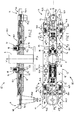
- the number 10 indicates the tool changer device as a whole, according to the afore-mentioned example of an embodiment of the invention.
- said mechanical and fully autonomous tool changer device 10 is mounted on a linearly translating head (of an already known type and not shown), for example in the direction of the Y axis, and has a contrasting surface S, against which the device is brought automatically and alternatively into contact, or in close proximity, without contact, by means of movements in a direction, for example X, essentially at a right angle to said direction of translation of the head.
- Said head is provided, in a known manner and therefore not shown, with a cam exchanger mechanism, respectively brushless motor means, that cause an ordered series of intermittent linear and rotary movements of an output shaft A, with an axis X-X to which is fixed a rigid arm 10.1, extending in at least one radial direction and carrying at least one tool-holder cone gripper.
- said arm 10.1 is symmetrically extended in two opposing radial directions with respect to said shaft A and supports, at a first free end, a first gripper 11 of a first tool-holder PU1 and, at a second free end, a second gripper 11 of a second tool-holder PU2, where the external diameter of said first tool-holder PU1 is greater than the external diameter of said second tool-holder PU2.
- each gripper 11 comprises:
- each double-joint lever 14.1 is partially resting against a respective outer protective cover 14.8, placed substantially flush with said double-joint lever and fixed to said box-type body 12.
- said rod member 17.1 of said shutter means 17 has, around said at least one through hole 15.2 of said blocking means 15, a surface portion that is conically countersunk towards the free end of the respective rod and, correspondingly, said at least one through hole 15.2 of said blocking means 15 has a conically countersunk circumferential portion with a shape that is substantially complementary to that of said conically countersunk surface portion of said rod member 17.1.
- said rigid arm 10.1 is symmetrically extended in two opposing radial directions with respect to the axis X-X of said shaft A and supports, at a first free end, a first gripper 11 of a first tool-holder PU1 and, at a second free end, a second gripper 11 of a second tool-holder PU2, where the external diameter of said first tool-holder PU1 is greater than the external diameter of said second tool-holder PU2.
- first gripper 11 and said second gripper 11 each comprise:
- said rod member 17.1 of said gripper 11 extends through a through hole 15.2 of said pair of through holes, near said shaft A, when said slide 13 is in said advanced position, and said rod member 17.1 of said gripper 11 extends through a through hole 15.2 of said pair of through holes, distal to said shaft A, when said slide 13 is in said set-back position.
- an aperture 15.3 is provided between said at least two through holes 15.2 of said blocking means 15 substantially in said direction (r), and permits the free passage of said rod member 17.1 from one hole to the other 15.2 of said at least two holes 15.2 and vice-versa.
- each gripper 11 mounted on the exchanger arm 10.1 has two spring-loaded clamps 14 that, when gripping a tool, open and adapt to the dimensions of the cone PU1, PU2, respectively.
- said two clamps 14 are blocked by the insertion of the shutter means 17 in the corresponding holes 15.2 of the blocking means 15, so that, during the exchange and translation phase of the exchanger arm 10.1, the tool cones PU1, PU2 are irreversibly blocked.
- the tool changer device achieves the objects set out in the introduction, in a simple, effective and safe manner.
Landscapes
- Engineering & Computer Science (AREA)
- Mechanical Engineering (AREA)
- Automatic Tool Replacement In Machine Tools (AREA)
Claims (5)
- Dispositif (10) de changement d'outil, monté sur une tête à translation linéaire et possédant une surface de butée (S), par rapport à laquelle le dispositif (10) même peut être porté de manière automatique et alternativement en contact, ou à proximité immédiate, et hors contact, au moyen de déplacements en direction essentiellement perpendiculaire à la direction de translation de la tête, dans laquelle sont prévus un mécanisme échangeur à came, c'est-à-dire des moyens à moteur brushless, qui entraînent une série ordonnée de mouvements intermittents, linéaires et rotatifs, d'un arbre de sortie (A), ayant un axe (X-X) et sur lequel est fixé un bras rigide (10.1), étendu dans au moins une direction radiale et adapté à porter au moins une pince (11) de préhension d'un cône porte-outil (PU1, PU2), où ladite au moins pince (11) comprend :- un corps de type boîtier (12), solidaire par rapport audit bras rigide (10.1), fermé au moyen d'un couvercle amovible (12.1) et dans lequel, dans une zone d'extrémité libre, sont prévus des moyens à glissière (13) mobile en mouvement alternatif rectiligne, selon la direction d'une droite (r) essentiellement perpendiculaire par rapport audit axe (X-X), le long de moyens de guidage de coulissement (12.2) correspondants, entre une position reculée proximale dudit arbre (A) et une position avancée distale dudit arbre (A) ;- une paire de mâchoires (14) de ladite pince (11), symétrique de manière spéculaire par rapport à un plan passant par ledit axe (X-X) et par ladite droite (r), où chaque mâchoire (14) de pince comprend un respectif levier à genouillère (14.1) incluant une première tige (14.2) et une deuxième tige (14.3) articulées entre elles sur une extrémité respective, au moyen d'un pivot commun (14.4) à axe parallèle audit axe (X-X), où ladite première tige (14.2) est articulée, en position intermédiaire, au moyen d'un pivot (14.5) fixe par rapport audit corps de type boîtier (12) et ayant un axe parallèle audit axe (X-X) et, à l'extrémité opposée, par rapport auxdits moyens à glissière (13), au moyen d'un pivot (14.6) fixé auxdits mêmes moyens à glissières (13) et ayant un axe parallèle audit axe (X-X), et ladite deuxième tige (14.3) est articulée, en position intermédiaire, au moyen d'un pivot (14.7) fixe par rapport audit corps de boîtier (12) et ayant un axe parallèle audit axe (X-X), où l'extrémité libre (12.8) de ladite deuxième tige (14.3) fait saillie par rapport à ladite extrémité libre dudit corps de type boîtier (12) et fournit une partie de préhension de la mâchoire (14) correspondante de ladite pince (11) ;où au moins une pince (11) comprend :- des moyens de blocage (15) solidaires par rapport auxdits moyens à glissière (13) et comprenant un organe à plaquette (15.1) possédant au moins un trou passant (15.2) à axe (Z-Z) parallèle audit axe (X-X) ;- des moyens élastiques (16) qui sont adaptés pour déplacer élastiquement lesdits moyens à glissière (13) vers ladite position avancée et lesdites mâchoires (14) en disposition réciproquement rapprochée de pince fermée ;- des moyens à obturateur (17), fixes par rapport audit bras (10.1) et comprenant un organe avec tige (17.1) étendu à travers ledit au moins trou passant (15.2) desdits moyens de blocage (15) et un trou passant (12.9) correspondant prévu dans ledit corps de type boîtier (12) ;- des moyens élastiques (18) qui maintiennent ledit organe avec tige (17.1) desdits moyens à obturateur (17) partiellement étendu au-delà dudit trou (12.9) dudit corps de type boîtier (12) et passant à travers ledit au moins trou (15.2) avec interférence, quand ledit dispositif (10) est hors contact par rapport à ladite surface de butée (S) de ladite tête fixe tandis que, lorsque ledit dispositif (10) est en contact, respectivement à proximité immédiate, par rapport à ladite surface de butée (S) de ladite tête, ladite tige (17.1) desdits moyens à obturateur (17) est rentrée dans ledit trou passant (12.9) dudit corps de type boîtier (12), en antagonisme à l'action desdits moyens élastiques (18), et est disposée passante sans interférence à travers ledit au moins trou (15.2).
- Dispositif selon la revendication 1, caractérisé par le fait que ledit organe avec tige (17.1) desdits moyens à obturateur (17) possède, autour dudit au moins trou passant (15.2) desdits moyens de blocage (15), une partie de surface coniquement évasée vers l'extrémité libre de la tige respective et, de manière correspondante, ledit au moins trous passant (15.2) desdits moyens de blocage (15) possède une position circonférentielle coniquement évasée et de forme substantiellement complémentaire à celle de ladite partie de surface coniquement évasée dudit organe avec tige (17.1).
- Dispositif selon l'une des revendications précédentes, où ledit bras rigide (10.1) est étendu symétriquement dans deux directions radiales opposées par rapport audit arbre (A), caractérisé par le fait que ledit arbre rigide (10.1) supporte, à une première extrémité libre, une première pince (11) de préhension d'un premier porte-outil (PU1) et, à une deuxième extrémité libre, une deuxième pince (11) de préhension d'un deuxième porte-outil (PU2), où le diamètre extérieur dudit premier porte-outil (PU1) est plus grand que celui dudit deuxième porte-outil (PU2), et par le fait que lorsque lesdits moyens à glissière (13) d'une pince (11) sont disposés dans ladite position reculée, proximale par rapport audit arbre (A), ils permettent l'ouverture réciproque desdites mâchoires (14) de la pince (11) correspondante par rapport audit porte-outil (PU1, PU2), et lorsque lesdits moyens à glissière (13) d'une pince (11) sont disposé dans ladite position avancée, distale par rapport audit arbre (A), ils assurent la fermeture réciproque desdites mâchoires (14) de la pince (11) correspondante en prise sur un porte-outil (PU1, PU2).
- Dispositif selon la revendication 3, caractérisé par le fait que ladite première pince (11) et ladite deuxième pince (11) comprennent chacune :- des moyens de blocage (15) respectifs solidaires par rapport aux moyens à glissière (13) correspondants, où un organe à plaquette (15.1) possède au moins deux trous passants (15.2) à axes (Z-Z) parallèles audit axe (X-X) et alignés entre eux en direction parallèle à ladite direction (r),- des moyens à obturateur (17) respectifs, fixes par rapport à un corps de type boîtier (12, 12.1) correspondant, où un organe avec tige (17.1) est étendu à travers un desdits au moins deux trous passants (15.2) desdits moyens de blocage (15) respectifs et à travers ledit trou passant (12.9) prévu dans ledit corps de type boîtier (12) ;et par le fait que ledit organe avec tige (17.1) d'une pince (11) est étendu à travers un trou passant (15.2) de ladite paire de trous passants, distal par rapport audit arbre (A), quand ladite glissière (13) est dans ladite position reculée, et ledit organe avec tige (17.1) d'une pince (11) est étendu à travers un trou passant (15.2) de ladite paire de trous passants, proximal par rapport audit arbre (A), quand ladite glissière (13) est dans ladite position avancée.
- Dispositif selon la revendication 4, caractérisé par le fait qu'il comprend une ouverture (15.3) étendue entre au moins lesdits deux trous passants (15.2) desdits moyens de blocage (15) substantiellement selon ladite direction (r), qui permet le passage libre dudit organe avec tige (17.1) de l'un à l'autre trou (15.2) desdits au moins deux trous (15.2) et inversement.
Applications Claiming Priority (2)
| Application Number | Priority Date | Filing Date | Title |
|---|---|---|---|
| IT102016000114326A IT201600114326A1 (it) | 2016-11-11 | 2016-11-11 | Dispositivo di cambio utensile |
| IT201700101093 | 2017-09-08 |
Publications (2)
| Publication Number | Publication Date |
|---|---|
| EP3321031A1 EP3321031A1 (fr) | 2018-05-16 |
| EP3321031B1 true EP3321031B1 (fr) | 2019-12-18 |
Family
ID=60269603
Family Applications (1)
| Application Number | Title | Priority Date | Filing Date |
|---|---|---|---|
| EP17001833.7A Active EP3321031B1 (fr) | 2016-11-11 | 2017-11-09 | Appareil comprenant un dispositif de changement d'outil et une tete de translation lineaire. |
Country Status (2)
| Country | Link |
|---|---|
| EP (1) | EP3321031B1 (fr) |
| ES (1) | ES2779003T3 (fr) |
Families Citing this family (6)
| Publication number | Priority date | Publication date | Assignee | Title |
|---|---|---|---|---|
| DE102021119171A1 (de) * | 2021-07-23 | 2023-01-26 | E. Zoller GmbH & Co. KG Einstell- und Messgeräte | Greifervorrichtung und Verfahren zum Betrieb einer Greifervorrichtung |
| CN113909981B (zh) * | 2021-09-29 | 2023-03-28 | 方冠(常州)数控科技有限公司 | 一种用于自动上下料的机械手总成 |
| EP4406695B1 (fr) * | 2023-01-26 | 2025-07-02 | VÚTS, a.s. | Dispositif de prehension pour bras manipulateur d'un systeme de manipulation pour l'echange automatique d'outils d'usinage |
| TWI870978B (zh) * | 2023-08-18 | 2025-01-21 | 聖杰國際股份有限公司 | 加工機之換刀機構 |
| TWI894859B (zh) * | 2024-03-15 | 2025-08-21 | 聖杰國際股份有限公司 | 自動換刀機構之換刀臂 |
| CN119223346B (zh) * | 2024-12-05 | 2025-02-25 | 山东高速工程检测有限公司 | 一种光纤光栅传感器的校准平台 |
Family Cites Families (3)
| Publication number | Priority date | Publication date | Assignee | Title |
|---|---|---|---|---|
| JP3547903B2 (ja) * | 1996-03-26 | 2004-07-28 | オークマ株式会社 | 盲蓋着脱方法 |
| JP2009255218A (ja) * | 2008-04-16 | 2009-11-05 | Pascal Engineering Corp | 工具交換用アーム装置 |
| CZ2013358A3 (cs) * | 2013-05-16 | 2014-09-24 | VĂšTS, a.s. | Podavač nástrojů manipulačního zařízení pro výměnu nástrojů na obráběcích strojích |
-
2017
- 2017-11-09 EP EP17001833.7A patent/EP3321031B1/fr active Active
- 2017-11-09 ES ES17001833T patent/ES2779003T3/es active Active
Non-Patent Citations (1)
| Title |
|---|
| None * |
Also Published As
| Publication number | Publication date |
|---|---|
| EP3321031A1 (fr) | 2018-05-16 |
| ES2779003T3 (es) | 2020-08-13 |
Similar Documents
| Publication | Publication Date | Title |
|---|---|---|
| EP3321031B1 (fr) | Appareil comprenant un dispositif de changement d'outil et une tete de translation lineaire. | |
| US3863940A (en) | Wide opening collet | |
| US5267766A (en) | Tool gripper | |
| EP2803444B1 (fr) | Dispositif d'alimentation d'outils pour un manipulateur pour l'échange d'outils dans une machine outil, comprenant un dispositif de sécurité | |
| JP6716505B2 (ja) | ワーク搬送装置 | |
| US9993902B2 (en) | Machine tool | |
| DE102017109360A1 (de) | Werkzeugmaschine | |
| US12296425B2 (en) | Clamping device and method for handling a workpiece | |
| DE102017111915A1 (de) | Werkzeugmaschine | |
| CN102896539A (zh) | 改进的刀具更换器 | |
| KR102409614B1 (ko) | 공작 기계 | |
| US20170348761A1 (en) | Gripping Device For Mechanical Fasteners | |
| JP6650290B2 (ja) | 工作機械 | |
| US4550922A (en) | Workholder | |
| US4700442A (en) | Tool changing apparatus for a machine tool | |
| US2732216A (en) | Indexing-type chuck | |
| US6783484B2 (en) | Machine tool with gripper and/ or tool magazine system | |
| KR20170069538A (ko) | 가공물 위치고정장치 | |
| KR102332109B1 (ko) | 공작기계 | |
| GB2083224A (en) | A connection device for securing insert carriers in measuring machines | |
| KR101713106B1 (ko) | 자동공구 교환장치용 툴매거진 | |
| EP3321030B1 (fr) | Dispositif de changement d'outil | |
| CN110026774B (zh) | 工件加工装置 | |
| EP3854520B1 (fr) | Système de traitement | |
| US11014206B2 (en) | Device for exchanging part of tool and hollow milling tool |
Legal Events
| Date | Code | Title | Description |
|---|---|---|---|
| PUAI | Public reference made under article 153(3) epc to a published international application that has entered the european phase |
Free format text: ORIGINAL CODE: 0009012 |
|
| STAA | Information on the status of an ep patent application or granted ep patent |
Free format text: STATUS: THE APPLICATION HAS BEEN PUBLISHED |
|
| AK | Designated contracting states |
Kind code of ref document: A1 Designated state(s): AL AT BE BG CH CY CZ DE DK EE ES FI FR GB GR HR HU IE IS IT LI LT LU LV MC MK MT NL NO PL PT RO RS SE SI SK SM TR |
|
| AX | Request for extension of the european patent |
Extension state: BA ME |
|
| STAA | Information on the status of an ep patent application or granted ep patent |
Free format text: STATUS: REQUEST FOR EXAMINATION WAS MADE |
|
| 17P | Request for examination filed |
Effective date: 20181112 |
|
| RBV | Designated contracting states (corrected) |
Designated state(s): AL AT BE BG CH CY CZ DE DK EE ES FI FR GB GR HR HU IE IS IT LI LT LU LV MC MK MT NL NO PL PT RO RS SE SI SK SM TR |
|
| GRAP | Despatch of communication of intention to grant a patent |
Free format text: ORIGINAL CODE: EPIDOSNIGR1 |
|
| STAA | Information on the status of an ep patent application or granted ep patent |
Free format text: STATUS: GRANT OF PATENT IS INTENDED |
|
| INTG | Intention to grant announced |
Effective date: 20190702 |
|
| GRAS | Grant fee paid |
Free format text: ORIGINAL CODE: EPIDOSNIGR3 |
|
| GRAA | (expected) grant |
Free format text: ORIGINAL CODE: 0009210 |
|
| STAA | Information on the status of an ep patent application or granted ep patent |
Free format text: STATUS: THE PATENT HAS BEEN GRANTED |
|
| AK | Designated contracting states |
Kind code of ref document: B1 Designated state(s): AL AT BE BG CH CY CZ DE DK EE ES FI FR GB GR HR HU IE IS IT LI LT LU LV MC MK MT NL NO PL PT RO RS SE SI SK SM TR |
|
| REG | Reference to a national code |
Ref country code: CH Ref legal event code: EP |
|
| REG | Reference to a national code |
Ref country code: IE Ref legal event code: FG4D |
|
| REG | Reference to a national code |
Ref country code: DE Ref legal event code: R096 Ref document number: 602017009697 Country of ref document: DE |
|
| REG | Reference to a national code |
Ref country code: AT Ref legal event code: REF Ref document number: 1214065 Country of ref document: AT Kind code of ref document: T Effective date: 20200115 |
|
| REG | Reference to a national code |
Ref country code: NL Ref legal event code: MP Effective date: 20191218 |
|
| PG25 | Lapsed in a contracting state [announced via postgrant information from national office to epo] |
Ref country code: LV Free format text: LAPSE BECAUSE OF FAILURE TO SUBMIT A TRANSLATION OF THE DESCRIPTION OR TO PAY THE FEE WITHIN THE PRESCRIBED TIME-LIMIT Effective date: 20191218 Ref country code: NO Free format text: LAPSE BECAUSE OF FAILURE TO SUBMIT A TRANSLATION OF THE DESCRIPTION OR TO PAY THE FEE WITHIN THE PRESCRIBED TIME-LIMIT Effective date: 20200318 Ref country code: GR Free format text: LAPSE BECAUSE OF FAILURE TO SUBMIT A TRANSLATION OF THE DESCRIPTION OR TO PAY THE FEE WITHIN THE PRESCRIBED TIME-LIMIT Effective date: 20200319 Ref country code: BG Free format text: LAPSE BECAUSE OF FAILURE TO SUBMIT A TRANSLATION OF THE DESCRIPTION OR TO PAY THE FEE WITHIN THE PRESCRIBED TIME-LIMIT Effective date: 20200318 Ref country code: FI Free format text: LAPSE BECAUSE OF FAILURE TO SUBMIT A TRANSLATION OF THE DESCRIPTION OR TO PAY THE FEE WITHIN THE PRESCRIBED TIME-LIMIT Effective date: 20191218 Ref country code: SE Free format text: LAPSE BECAUSE OF FAILURE TO SUBMIT A TRANSLATION OF THE DESCRIPTION OR TO PAY THE FEE WITHIN THE PRESCRIBED TIME-LIMIT Effective date: 20191218 Ref country code: LT Free format text: LAPSE BECAUSE OF FAILURE TO SUBMIT A TRANSLATION OF THE DESCRIPTION OR TO PAY THE FEE WITHIN THE PRESCRIBED TIME-LIMIT Effective date: 20191218 |
|
| REG | Reference to a national code |
Ref country code: LT Ref legal event code: MG4D |
|
| PG25 | Lapsed in a contracting state [announced via postgrant information from national office to epo] |
Ref country code: HR Free format text: LAPSE BECAUSE OF FAILURE TO SUBMIT A TRANSLATION OF THE DESCRIPTION OR TO PAY THE FEE WITHIN THE PRESCRIBED TIME-LIMIT Effective date: 20191218 Ref country code: RS Free format text: LAPSE BECAUSE OF FAILURE TO SUBMIT A TRANSLATION OF THE DESCRIPTION OR TO PAY THE FEE WITHIN THE PRESCRIBED TIME-LIMIT Effective date: 20191218 |
|
| PG25 | Lapsed in a contracting state [announced via postgrant information from national office to epo] |
Ref country code: AL Free format text: LAPSE BECAUSE OF FAILURE TO SUBMIT A TRANSLATION OF THE DESCRIPTION OR TO PAY THE FEE WITHIN THE PRESCRIBED TIME-LIMIT Effective date: 20191218 |
|
| PG25 | Lapsed in a contracting state [announced via postgrant information from national office to epo] |
Ref country code: RO Free format text: LAPSE BECAUSE OF FAILURE TO SUBMIT A TRANSLATION OF THE DESCRIPTION OR TO PAY THE FEE WITHIN THE PRESCRIBED TIME-LIMIT Effective date: 20191218 Ref country code: PT Free format text: LAPSE BECAUSE OF FAILURE TO SUBMIT A TRANSLATION OF THE DESCRIPTION OR TO PAY THE FEE WITHIN THE PRESCRIBED TIME-LIMIT Effective date: 20200513 Ref country code: EE Free format text: LAPSE BECAUSE OF FAILURE TO SUBMIT A TRANSLATION OF THE DESCRIPTION OR TO PAY THE FEE WITHIN THE PRESCRIBED TIME-LIMIT Effective date: 20191218 Ref country code: NL Free format text: LAPSE BECAUSE OF FAILURE TO SUBMIT A TRANSLATION OF THE DESCRIPTION OR TO PAY THE FEE WITHIN THE PRESCRIBED TIME-LIMIT Effective date: 20191218 |
|
| REG | Reference to a national code |
Ref country code: ES Ref legal event code: FG2A Ref document number: 2779003 Country of ref document: ES Kind code of ref document: T3 Effective date: 20200813 |
|
| PG25 | Lapsed in a contracting state [announced via postgrant information from national office to epo] |
Ref country code: SK Free format text: LAPSE BECAUSE OF FAILURE TO SUBMIT A TRANSLATION OF THE DESCRIPTION OR TO PAY THE FEE WITHIN THE PRESCRIBED TIME-LIMIT Effective date: 20191218 Ref country code: SM Free format text: LAPSE BECAUSE OF FAILURE TO SUBMIT A TRANSLATION OF THE DESCRIPTION OR TO PAY THE FEE WITHIN THE PRESCRIBED TIME-LIMIT Effective date: 20191218 Ref country code: IS Free format text: LAPSE BECAUSE OF FAILURE TO SUBMIT A TRANSLATION OF THE DESCRIPTION OR TO PAY THE FEE WITHIN THE PRESCRIBED TIME-LIMIT Effective date: 20200418 |
|
| REG | Reference to a national code |
Ref country code: DE Ref legal event code: R097 Ref document number: 602017009697 Country of ref document: DE |
|
| REG | Reference to a national code |
Ref country code: AT Ref legal event code: MK05 Ref document number: 1214065 Country of ref document: AT Kind code of ref document: T Effective date: 20191218 |
|
| PLBE | No opposition filed within time limit |
Free format text: ORIGINAL CODE: 0009261 |
|
| STAA | Information on the status of an ep patent application or granted ep patent |
Free format text: STATUS: NO OPPOSITION FILED WITHIN TIME LIMIT |
|
| PG25 | Lapsed in a contracting state [announced via postgrant information from national office to epo] |
Ref country code: DK Free format text: LAPSE BECAUSE OF FAILURE TO SUBMIT A TRANSLATION OF THE DESCRIPTION OR TO PAY THE FEE WITHIN THE PRESCRIBED TIME-LIMIT Effective date: 20191218 |
|
| 26N | No opposition filed |
Effective date: 20200921 |
|
| PG25 | Lapsed in a contracting state [announced via postgrant information from national office to epo] |
Ref country code: AT Free format text: LAPSE BECAUSE OF FAILURE TO SUBMIT A TRANSLATION OF THE DESCRIPTION OR TO PAY THE FEE WITHIN THE PRESCRIBED TIME-LIMIT Effective date: 20191218 Ref country code: SI Free format text: LAPSE BECAUSE OF FAILURE TO SUBMIT A TRANSLATION OF THE DESCRIPTION OR TO PAY THE FEE WITHIN THE PRESCRIBED TIME-LIMIT Effective date: 20191218 |
|
| PG25 | Lapsed in a contracting state [announced via postgrant information from national office to epo] |
Ref country code: IT Free format text: LAPSE BECAUSE OF FAILURE TO SUBMIT A TRANSLATION OF THE DESCRIPTION OR TO PAY THE FEE WITHIN THE PRESCRIBED TIME-LIMIT Effective date: 20191218 |
|
| PG25 | Lapsed in a contracting state [announced via postgrant information from national office to epo] |
Ref country code: PL Free format text: LAPSE BECAUSE OF FAILURE TO SUBMIT A TRANSLATION OF THE DESCRIPTION OR TO PAY THE FEE WITHIN THE PRESCRIBED TIME-LIMIT Effective date: 20191218 |
|
| PG25 | Lapsed in a contracting state [announced via postgrant information from national office to epo] |
Ref country code: MC Free format text: LAPSE BECAUSE OF FAILURE TO SUBMIT A TRANSLATION OF THE DESCRIPTION OR TO PAY THE FEE WITHIN THE PRESCRIBED TIME-LIMIT Effective date: 20191218 |
|
| PG25 | Lapsed in a contracting state [announced via postgrant information from national office to epo] |
Ref country code: LU Free format text: LAPSE BECAUSE OF NON-PAYMENT OF DUE FEES Effective date: 20201109 |
|
| REG | Reference to a national code |
Ref country code: BE Ref legal event code: MM Effective date: 20201130 |
|
| PG25 | Lapsed in a contracting state [announced via postgrant information from national office to epo] |
Ref country code: FR Free format text: LAPSE BECAUSE OF NON-PAYMENT OF DUE FEES Effective date: 20201130 Ref country code: IE Free format text: LAPSE BECAUSE OF NON-PAYMENT OF DUE FEES Effective date: 20201109 |
|
| PGFP | Annual fee paid to national office [announced via postgrant information from national office to epo] |
Ref country code: CZ Payment date: 20211130 Year of fee payment: 5 Ref country code: DE Payment date: 20211210 Year of fee payment: 5 |
|
| PGFP | Annual fee paid to national office [announced via postgrant information from national office to epo] |
Ref country code: CH Payment date: 20211223 Year of fee payment: 5 |
|
| PG25 | Lapsed in a contracting state [announced via postgrant information from national office to epo] |
Ref country code: TR Free format text: LAPSE BECAUSE OF FAILURE TO SUBMIT A TRANSLATION OF THE DESCRIPTION OR TO PAY THE FEE WITHIN THE PRESCRIBED TIME-LIMIT Effective date: 20191218 Ref country code: MT Free format text: LAPSE BECAUSE OF FAILURE TO SUBMIT A TRANSLATION OF THE DESCRIPTION OR TO PAY THE FEE WITHIN THE PRESCRIBED TIME-LIMIT Effective date: 20191218 Ref country code: CY Free format text: LAPSE BECAUSE OF FAILURE TO SUBMIT A TRANSLATION OF THE DESCRIPTION OR TO PAY THE FEE WITHIN THE PRESCRIBED TIME-LIMIT Effective date: 20191218 |
|
| PGFP | Annual fee paid to national office [announced via postgrant information from national office to epo] |
Ref country code: ES Payment date: 20220104 Year of fee payment: 5 |
|
| PG25 | Lapsed in a contracting state [announced via postgrant information from national office to epo] |
Ref country code: MK Free format text: LAPSE BECAUSE OF FAILURE TO SUBMIT A TRANSLATION OF THE DESCRIPTION OR TO PAY THE FEE WITHIN THE PRESCRIBED TIME-LIMIT Effective date: 20191218 |
|
| GBPC | Gb: european patent ceased through non-payment of renewal fee |
Effective date: 20211109 |
|
| PG25 | Lapsed in a contracting state [announced via postgrant information from national office to epo] |
Ref country code: BE Free format text: LAPSE BECAUSE OF NON-PAYMENT OF DUE FEES Effective date: 20201130 |
|
| PG25 | Lapsed in a contracting state [announced via postgrant information from national office to epo] |
Ref country code: GB Free format text: LAPSE BECAUSE OF NON-PAYMENT OF DUE FEES Effective date: 20211109 |
|
| REG | Reference to a national code |
Ref country code: DE Ref legal event code: R119 Ref document number: 602017009697 Country of ref document: DE |
|
| REG | Reference to a national code |
Ref country code: CH Ref legal event code: PL |
|
| PG25 | Lapsed in a contracting state [announced via postgrant information from national office to epo] |
Ref country code: LI Free format text: LAPSE BECAUSE OF NON-PAYMENT OF DUE FEES Effective date: 20221130 Ref country code: CZ Free format text: LAPSE BECAUSE OF NON-PAYMENT OF DUE FEES Effective date: 20221109 Ref country code: CH Free format text: LAPSE BECAUSE OF NON-PAYMENT OF DUE FEES Effective date: 20221130 |
|
| PG25 | Lapsed in a contracting state [announced via postgrant information from national office to epo] |
Ref country code: DE Free format text: LAPSE BECAUSE OF NON-PAYMENT OF DUE FEES Effective date: 20230601 |
|
| REG | Reference to a national code |
Ref country code: ES Ref legal event code: FD2A Effective date: 20231228 |
|
| PG25 | Lapsed in a contracting state [announced via postgrant information from national office to epo] |
Ref country code: ES Free format text: LAPSE BECAUSE OF NON-PAYMENT OF DUE FEES Effective date: 20221110 |
|
| PG25 | Lapsed in a contracting state [announced via postgrant information from national office to epo] |
Ref country code: ES Free format text: LAPSE BECAUSE OF NON-PAYMENT OF DUE FEES Effective date: 20221110 |