EP3321038B1 - Dispositif d'entraînement de fixation de ressort à gaz - Google Patents
Dispositif d'entraînement de fixation de ressort à gaz Download PDFInfo
- Publication number
- EP3321038B1 EP3321038B1 EP17200840.1A EP17200840A EP3321038B1 EP 3321038 B1 EP3321038 B1 EP 3321038B1 EP 17200840 A EP17200840 A EP 17200840A EP 3321038 B1 EP3321038 B1 EP 3321038B1
- Authority
- EP
- European Patent Office
- Prior art keywords
- nosepiece
- magazine
- battery
- fastener
- driver
- Prior art date
- Legal status (The legal status is an assumption and is not a legal conclusion. Google has not performed a legal analysis and makes no representation as to the accuracy of the status listed.)
- Active
Links
Images
Classifications
-
- B—PERFORMING OPERATIONS; TRANSPORTING
- B25—HAND TOOLS; PORTABLE POWER-DRIVEN TOOLS; MANIPULATORS
- B25C—HAND-HELD NAILING OR STAPLING TOOLS; MANUALLY OPERATED PORTABLE STAPLING TOOLS
- B25C1/00—Hand-held nailing tools; Nail feeding devices
- B25C1/04—Hand-held nailing tools; Nail feeding devices operated by fluid pressure, e.g. by air pressure
- B25C1/047—Mechanical details
-
- B—PERFORMING OPERATIONS; TRANSPORTING
- B25—HAND TOOLS; PORTABLE POWER-DRIVEN TOOLS; MANIPULATORS
- B25C—HAND-HELD NAILING OR STAPLING TOOLS; MANUALLY OPERATED PORTABLE STAPLING TOOLS
- B25C1/00—Hand-held nailing tools; Nail feeding devices
- B25C1/04—Hand-held nailing tools; Nail feeding devices operated by fluid pressure, e.g. by air pressure
- B25C1/041—Hand-held nailing tools; Nail feeding devices operated by fluid pressure, e.g. by air pressure with fixed main cylinder
-
- B—PERFORMING OPERATIONS; TRANSPORTING
- B25—HAND TOOLS; PORTABLE POWER-DRIVEN TOOLS; MANIPULATORS
- B25C—HAND-HELD NAILING OR STAPLING TOOLS; MANUALLY OPERATED PORTABLE STAPLING TOOLS
- B25C1/00—Hand-held nailing tools; Nail feeding devices
- B25C1/008—Safety devices
-
- B—PERFORMING OPERATIONS; TRANSPORTING
- B25—HAND TOOLS; PORTABLE POWER-DRIVEN TOOLS; MANIPULATORS
- B25C—HAND-HELD NAILING OR STAPLING TOOLS; MANUALLY OPERATED PORTABLE STAPLING TOOLS
- B25C1/00—Hand-held nailing tools; Nail feeding devices
- B25C1/06—Hand-held nailing tools; Nail feeding devices operated by electric power
-
- B—PERFORMING OPERATIONS; TRANSPORTING
- B25—HAND TOOLS; PORTABLE POWER-DRIVEN TOOLS; MANIPULATORS
- B25C—HAND-HELD NAILING OR STAPLING TOOLS; MANUALLY OPERATED PORTABLE STAPLING TOOLS
- B25C5/00—Manually operated portable stapling tools; Hand-held power-operated stapling tools; Staple feeding devices therefor
- B25C5/10—Driving means
- B25C5/13—Driving means operated by fluid pressure
-
- Y—GENERAL TAGGING OF NEW TECHNOLOGICAL DEVELOPMENTS; GENERAL TAGGING OF CROSS-SECTIONAL TECHNOLOGIES SPANNING OVER SEVERAL SECTIONS OF THE IPC; TECHNICAL SUBJECTS COVERED BY FORMER USPC CROSS-REFERENCE ART COLLECTIONS [XRACs] AND DIGESTS
- Y02—TECHNOLOGIES OR APPLICATIONS FOR MITIGATION OR ADAPTATION AGAINST CLIMATE CHANGE
- Y02E—REDUCTION OF GREENHOUSE GAS [GHG] EMISSIONS, RELATED TO ENERGY GENERATION, TRANSMISSION OR DISTRIBUTION
- Y02E60/00—Enabling technologies; Technologies with a potential or indirect contribution to GHG emissions mitigation
- Y02E60/10—Energy storage using batteries
Definitions
- the present invention relates to power tools, and more particularly to gas spring fastener drivers.
- fastener drivers used to drive fasteners (e.g., nails, tacks, staples, etc.) into a workpiece known in the art.
- fastener drivers operate utilizing various means (e.g., compressed air generated by an air compressor, electrical energy, flywheel mechanisms) known in the art, but often these designs are met with power, size, and cost constraints.
- JP2005001065 relates to a fastener driver according to the preamble of claim 1 .
- a driving-in machine including a cover of a magazine, which, when opened, an engaging arm 52b comes off a terminal plate 63, and the terminal plate 63 is spaced from a contact 60a of the battery 60 to intercept current flowing to the battery 60.
- the charging of the driven members can thereby be performed in a state of inhibiting unprepared driving-in operation without performing special operation.
- a fastener driver including a housing, a cylinder disposed within the housing, a piston positioned and movable within the cylinder, a driver blade attached to the piston and movable with the piston, a motor for driving movement of the piston, a battery removably coupled to the housing for supplying power to the motor, a nosepiece at least partially defining a fastener driving track through which fasteners are driven by the driver blade, and a magazine operable to supply the fasteners to the nosepiece.
- the magazine is removable from the nosepiece only in response to prior removal of the battery from the housing.
- the magazine includes a blocking member engageable with the battery to prevent removal of the magazine from the nosepiece when the battery is coupled to the main housing.
- the nosepiece may be a front nosepiece and the fastener driver may further comprise a rear nosepiece attached to the magazine.
- the fastener driving track may be defined between the front nosepiece and the rear nosepiece.
- the fastener driver may further comprise a quick-release latch that is operable to secure the front nosepiece and the rear nosepiece together.
- the rear nosepiece may include two hooks, respectively, positioned on opposite sides of the fastener driving track.
- the quick-release latch may be engaged with the hooks to secure the front nosepiece and the rear nosepiece together.
- the front nosepiece may define respective apertures through which the hooks extend.
- the quick-release latch may include a lever and a spring pivotably coupled to the lever.
- the lever may be pivotably coupled to the front nosepiece.
- the quick-release latch may further include spaced pins positioned on a lower end of the spring and engageable with the hooks, respectively, for securing the front nosepiece and the rear nosepiece together.
- the magazine may include a blocking member located between a driving axis coaxial with the driver blade and the battery.
- the blocking member may laterally protrude from a side of the magazine closest to the battery.
- the blocking member and the battery may define a first axial gap in a direction parallel with an insertion axis of the battery when the battery is coupled to the housing to supply power to the motor.
- the blocking member may be engageable with the battery, which may thereby prevent further movement of the magazine in the direction parallel with the insertion axis, when the quick-release latch is disengaged from the hooks.
- the rear nosepiece may be separable from the front nosepiece by a second axial gap equal to the first axial gap when the blocking member is engaged with the battery.
- the hooks may be at least partially positioned within the respective apertures in the front nosepiece when the rear nosepiece is separated from the front nosepiece by the second axial gap.
- the rear nosepiece and the magazine may be removably coupled to the front nosepiece as a unit.
- the fastener driver may further comprise an electrical switch operable to detect when the rear nosepiece is removed from the front nosepiece. Activation of the motor may be inhibited in response to the electrical switch detecting removal of the rear nosepiece from the front nosepiece.
- the electrical switch may be coupled to the front nosepiece.
- the rear nosepiece may include a projection engageable with the electrical switch when the rear nosepiece is coupled to the front nosepiece. The projection may disengage the electrical switch in response to removal of the rear nosepiece from the front nosepiece.
- a fastener driver may include a cylinder, a piston positioned and moveable within the cylinder, a driver blade attached to the piston and moveable with the piston, a front nosepiece at least partially defining a fastener driving track through which fasteners are driven by the driver blade, a rear nosepiece at least partially defining the fastener driving track, and a magazine attached to the rear nosepiece and operable to supply the fasteners to the fastener driver track through the rear nosepiece.
- the rear nosepiece and the magazine are removably coupled to the front nosepiece as a unit.
- the fastener driver may further comprise an electrical switch operable to detect when the rear nosepiece is removed from the front nosepiece.
- the fastener driver may further comprise a motor for driving movement of the piston. Activation of the motor may be inhibited in response to the electrical switch detecting removal of the rear nosepiece from the front nosepiece.
- the electrical switch may be coupled to the front nosepiece.
- the rear nosepiece may include a projection engageable with the electrical switch when the rear nosepiece is coupled to the front nosepiece. The projection may disengage the electrical switch in response to removal of the rear nosepiece from the front nosepiece.
- the present invention provides, in yet another aspect, a method of operating a fastener driver according to the previous aspect of the invention.
- the method includes initiating a fastener driving operation by moving the driver blade, with a gas spring mechanism, from a retracted position toward a driven position, stopping the driver blade at an intermediate position between the retracted position and the driven position in response to a fastener jammed in the fastener driving track, detaching the battery from the fastener driver, and removing the magazine from the nosepiece, after the battery has been removed.
- the method may further comprise actuating a switch in response to removal of the magazine from the nosepiece, which may thereby inhibit further operation of the fastener driver.
- the method may further comprise: removing the jammed fastener in the fastener driving track; and reattaching the magazine to the nosepiece.
- the method may still further comprise actuating the switch in response to reattachment of the magazine to the nosepiece, which may thereby return the fastener driver to an operational state.
- the method may further comprise reattaching the battery to the fastener driver after reattachment of the magazine to the nosepiece.
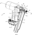
- a gas spring fastener driver 10 for driving fasteners 12 (e.g., nails, tacks, staples, etc.) into a workpiece is shown.
- the fastener driver 10 includes a housing 14, a nosepiece 16 extending from the main housing 14, and a magazine 18 for sequentially feeding fasteners 12 (e.g., collated fasteners) into the nosepiece 16 prior to each fastener-driving operation.
- the magazine 18 of the illustrated embodiment is composed of a magnesium material, in other embodiments, the magazine 18 can alternatively be composed of a different metal or metal allow, or other suitable materials.
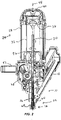
- the fastener driver 10 also includes a drive blade 20 and an onboard gas spring mechanism 24 for driving the drive blade 20 coinciding with ejection of a fastener 12 from the nosepiece 16. Accordingly, the fastener driver 10 does not require an external source of air pressure for driving the drive blade 20. Rather, the gas spring mechanism 24 includes a storage chamber 28 of pressurized gas in fluid communication with a cylinder 32. The cylinder 32 and a moveable piston 36 are positioned within the storage chamber 28.
- the cylinder 32 and the drive blade 20 define a driving axis 44, and during a driving cycle the drive blade 20 and the piston 36 are moveable along the driving axis 44 between a ready position (i.e., top dead center; see FIG. 2 ) and a driven position (i.e., bottom dead center).
- a ready position i.e., top dead center; see FIG. 2
- a driven position i.e., bottom dead center
- the fastener driver 10 further includes a lifting assembly 48, which is powered by a motor 52, and which is operable to move the drive blade 20 from the driven position to the ready position.
- the drive blade 20 is biased to the driven position by compressed gas in the storage chamber 28.
- the fastener driver 10 further includes a handle 56 that is grasped by an operator for maneuvering the fastener driver 10.
- the handle 56 and the motor 52 are both oriented substantially perpendicular to the driving axis 44.
- the fastener driver 10 includes a battery 60 that is removably coupled to the handle 56 along a battery insertion/removal axis 62 that is also perpendicular to the driving axis 44.
- the battery 60 is electrically connectable to the motor 52 for supplying electrical power to the motor 52 to drive the lifting assembly 48.
- the lifting assembly 48 raises the piston 36 and the drive blade 20 from the driven position and toward the ready position by energizing the motor 52.
- the gas above the piston 36 and the gas within the storage chamber 28 is compressed.
- the piston 36 and the drive blade 20 are held in position until released by user activation of a trigger (not shown).
- the compressed gas above the piston 36 and within the storage chamber 28 drives the piston 36 and the drive blade 20 to the driven position, thereby driving a fastener into a workpiece.
- the illustrated fastener driver 10 therefore operates on a gas spring principle utilizing the lifting assembly 48 and the piston 36 to further compress the gas within the cylinder 32 and the storage chamber 28. Further detail regarding the structure and operation of the fastener driver 10 is provided below.
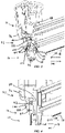
- the nosepiece 16 further includes a front nosepiece 64, a rear nosepiece 68, and an over-center spring latch 72 (i.e., a quick-release latch) operable to secure the rear nosepiece 68 to the front nosepiece 64.
- an over-center spring latch 72 i.e., a quick-release latch operable to secure the rear nosepiece 68 to the front nosepiece 64.
- attaching the rear nosepiece 68 to the front nosepiece 64 also attaches the magazine 18 to the front nosepiece 64.
- a fastener driving track or channel 76 is formed therebetween ( FIG. 3 ).
- the fastener driving track 76 is coaxial with the driving axis 44 and is in communication with the magazine 18 in order to sequentially receive the fasteners 12 from the magazine 18 for consecutive fastener driving operations.
- the rear nosepiece 68 includes a first pair of projections 80 and a second pair of hooks or projections 84, both of which extend away from the rear nosepiece 68 toward the front nosepiece 64, positioned on opposite sides of the fastener driving track 76.
- the first pair of projections 80 extend into corresponding slots 88 defined in the front nosepiece 64.
- an electrical switch 92 e.g., a microswitch, FIG.
- each of the slots 88 may contain a switch 92 to detect when the rear nosepiece 68 is connected to and removed from the front nosepiece 64.
- the spring latch 72 includes a lever 96 pivotably coupled to the front nosepiece 64 and a spring member 100, including spaced pins 103, that is pivotably coupled to the lever 96 in an over-center-type configuration.
- the spring member 100 is engageable (via pins 103) with the second pair of projections 84, which are configured as hooks, that extend through respective apertures 102 in the front nosepiece 64.
- the spring member 100 exerts a clamping force against the projections 84, preventing them from being removed from the apertures 102.
- the rear nosepiece 68 and the magazine 18 are retained to the front nosepiece 64 in an engaged position, as shown in FIG. 3 .
- the spring member 100 releases the clamping force on the projections 84, permitting the spring member 100 to be pivoted away from the front nosepiece 64, and permitting the rear nosepiece 68 (with the attached magazine 18) to be moved in a rearward direction (i.e., toward a disengaged position shown in FIG. 4 ).
- the rear nosepiece 68 and magazine 18 move along a first (i.e., rearward) direction 104 when moving toward the disengaged position and along a second (i.e., forward) direction 108 when moving toward the engaged position.
- the magazine 18 includes a blocking member 112 laterally protruding from a side thereof closest to the housing 14 and battery 60.
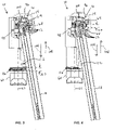
- the blocking member 112 is located between the driving axis 44, which is coaxial with the drive blade 20, and the battery 60 ( FIG. 1 ). As shown in FIGS. 5 and 6 , the blocking member 112 protrudes from the magazine 18 by a sufficient amount to overlap a portion of the battery 60.
- the blocking member 112 acts as a safety mechanism because an operator is required to remove the battery 60 (thereby disconnecting any power to the motor 52) prior to removing the magazine 18 for clearing a jammed fastener 12 from the nosepiece 16. By removing the battery 60, any inadvertent fastening operations are avoided.
- the blocking member 112 interferes with a shoulder 116 ( FIG. 6 ) of the battery 60 if removal of the magazine 18 from the nosepiece 16 is attempted prior to removing the battery 60. In the engaged position of the rear nosepiece 68 and magazine 18, a gap 120 exists between the shoulder 116 of the battery 60 and the blocking member 112 ( FIG. 5 ).
- the rear nosepiece 68 and magazine 18 may be moved in direction 104 until the blocking member 112 abuts the shoulder 116, thereby limiting any further movement of the magazine 18 in direction 104 so long as the battery 60 remains attached to the housing 14.
- the gap 120 now exists between the front nosepiece 64 and the rear nosepiece 68.
- the projections 84 remain within the apertures 102 ( FIG. 3 ), preventing the magazine 18 from being removed as long as the battery 60 remains attached to the housing 14.
- the fastener driver 10 will remain deactivated, despite reattachment of the battery 60, until the rear nosepiece 68 and magazine 18 are reattached to the front nosepiece 64.
- the projection 80 contacts and closes the switch 92 (if it is normally open), thereby returning the fastener driver 10 to an active or operational state in which a fastener firing operation may be initiated.
Landscapes
- Engineering & Computer Science (AREA)
- Mechanical Engineering (AREA)
- Physics & Mathematics (AREA)
- Fluid Mechanics (AREA)
- Portable Nailing Machines And Staplers (AREA)
Claims (11)
- Système d'entraînement d'élément de fixation (10) comprenant :un boîtier (14) ;un cylindre (32) disposé au sein du boîtier ;un piston (36) positionné et mobile au sein du cylindre ;une lame d'entraînement (20) attachée au piston et mobile avec le piston ;un moteur (52) pour entraîner un mouvement du piston ;une batterie (60) couplée de manière amovible au boîtier pour fournir de l'énergie au moteur ;un embout (16) définissant au moins partiellement une piste d'entraînement d'élément de fixation (76) à travers laquelle des éléments de fixation (12) sont entraînés par la lame d'entraînement ; etun chargeur (18) pouvant fonctionner pour fournir les éléments de fixation à l'embout, caractérisé en ce que le chargeur inclut un organe de blocage (112) pouvant venir en prise avec la batterie pour empêcher un retrait du chargeur de l'embout lorsque la batterie est couplée au boîtier principal, et le chargeur est amovible de l'embout uniquement en réponse au retrait préalable de la batterie du boîtier.
- Système d'entraînement d'élément de fixation selon la revendication 1, dans lequel l'embout (16) est un embout avant (64), dans lequel le système d'entraînement d'élément de fixation comprend en outre un embout arrière (68) attaché au chargeur (18), et dans lequel la piste d'entraînement d'élément de fixation est définie entre l'embout avant et l'embout arrière ;de préférence,le système d'entraînement d'élément de fixation comprend en outre un verrou à libération rapide (72) qui peut fonctionner pour maintenir l'embout avant (64) et l'embout arrière (68) ensemble ;plus préférablement,l'embout arrière (68) inclut deux crochets (84), respectivement, positionnés sur des côtés opposés de la piste d'entraînement d'élément de fixation (76), et dans lequel le verrou à libération rapide (72) vient en prise avec les crochets pour maintenir l'embout avant (64) et l'embout arrière (68) ensemble ; etle plus préférablement,l'embout avant (64) définit des ouvertures (102) respectives à travers lesquelles les crochets (84) s'étendent.
- Système d'entraînement d'élément de fixation selon la revendication 2, dans lequel le verrou à libération rapide (72) inclut un levier (96) et un ressort (100) couplé de manière pivotante au levier, dans lequel le levier est couplé de manière pivotante à l'embout avant (64) ; etéventuellement,le verrou à libération rapide (72) inclut en outre des broches espacées (103) positionnées sur une extrémité inférieure du ressort (100) et pouvant venir en prise avec les crochets (84), respectivement, pour maintenir l'embout avant (64) et l'embout arrière (68) ensemble.
- Système d'entraînement d'élément de fixation selon la revendication 2, dans lequel l'organe de blocage (112) est situé entre un axe d'entraînement (44) coaxial avec la lame d'entraînement (20) et la batterie (60), et dans lequel l'organe de blocage (112) dépasse latéralement d'un côté du chargeur (18) le plus proche de la batterie ; etde préférence,l'organe de blocage (112) et la batterie (60) définissent un premier espace axial dans une direction parallèle à un axe d'insertion (62) de la batterie lorsque la batterie est couplée au boîtier (14) pour fournir de l'énergie au moteur (52).
- Système d'entraînement d'élément de fixation selon la revendication 4, dans lequel l'organe de blocage (112) peut venir en prise avec la batterie (60), empêchant de ce fait un mouvement supplémentaire du chargeur (18) dans la direction parallèle à l'axe d'insertion (62), lorsque le verrou à libération rapide (72) est désengagé des crochets (84) ; etde préférence,l'embout arrière (68) est séparable de l'embout avant (64) par un second espace axial égal au premier espace axial lorsque l'organe de blocage (112) vient en prise avec la batterie (60) ; etplus préférablement,les crochets (84) sont au moins partiellement positionnés au sein des ouvertures (102) respectives dans l'embout avant (64) lorsque l'embout arrière (68) est séparé de l'embout avant par le second espace axial.
- Système d'entraînement d'élément de fixation selon la revendication 2, dans lequel l'embout arrière (68) et le chargeur (18) sont couplés de manière amovible à l'embout avant (64) en tant qu'unité ; etde préférence,le système d'entraînement d'élément de fixation comprend en outre un commutateur électrique (92) pouvant fonctionner pour détecter le moment où l'embout arrière (68) est retiré de l'embout avant (64).
- Système d'entraînement d'élément de fixation selon la revendication 6, dans lequel l'activation du moteur (52) est inhibée en réponse au commutateur électrique (92) détectant un retrait de l'embout arrière (68) de l'embout avant (64) ; etde préférence,le commutateur électrique (92) est couplé à l'embout avant (64), et dans lequel l'embout arrière (68) inclut une saillie (80) pouvant venir en prise avec le commutateur électrique (92) lorsque l'embout arrière est couplé à l'embout avant ; etplus préférablement,la saillie (80) désengage le commutateur électrique (92) en réponse à un retrait de l'embout arrière (68) de l'embout avant (64).
- Procédé de fonctionnement d'un système d'entraînement d'élément de fixation (10) selon l'une quelconque des revendications 1 à 7, le procédé comprenant :le lancement d'un fonctionnement d'entraînement d'élément de fixation en déplaçant la lame d'entraînement (20), avec un mécanisme à ressort à gaz (24), d'une position rétractée vers une position entraînée ;l'arrêt de la lame d'entraînement (20) à une position intermédiaire entre la position rétractée et la position entraînée en réponse à un élément de fixation (12) coincé dans la piste d'entraînement d'élément de fixation (76) ;le détachement de la batterie (60) du système d'entraînement d'élément de fixation ; etle retrait du chargeur (18) de l'embout (16), après que la batterie (60) a été retirée.
- Procédé selon la revendication 8, avant le retrait de la batterie (60), bloquant un retrait du chargeur (18) de l'embout (16) en réponse à un contact entre l'organe de blocage (112) sur le chargeur et la batterie attachée.
- Procédé selon la revendication 8, comprenant en outre l'actionnement du commutateur (92) en réponse à un retrait du chargeur (18) de l'embout (16), inhibant de ce fait un fonctionnement supplémentaire du système d'entraînement d'élément de fixation.
- Procédé selon la revendication 10, comprenant en outre :le retrait de l'élément de fixation (12) coincé dans la piste d'entraînement d'élément de fixation (76) ; etle rattachement du chargeur (18) à l'embout (16) ; etde préférence,le procédé comprend en outre l'actionnement du commutateur (92) en réponse à un rattachement du chargeur (18) à l'embout (16), ramenant de ce fait le système d'entraînement d'élément de fixation à un état de fonctionnement ; etplus préférablement,le procédé comprend en outre le rattachement de la batterie (60) au système d'entraînement d'élément de fixation après rattachement du chargeur (18) à l'embout (16).
Applications Claiming Priority (1)
| Application Number | Priority Date | Filing Date | Title |
|---|---|---|---|
| US201662419719P | 2016-11-09 | 2016-11-09 |
Publications (3)
| Publication Number | Publication Date |
|---|---|
| EP3321038A2 EP3321038A2 (fr) | 2018-05-16 |
| EP3321038A3 EP3321038A3 (fr) | 2018-07-25 |
| EP3321038B1 true EP3321038B1 (fr) | 2022-05-11 |
Family
ID=60293885
Family Applications (1)
| Application Number | Title | Priority Date | Filing Date |
|---|---|---|---|
| EP17200840.1A Active EP3321038B1 (fr) | 2016-11-09 | 2017-11-09 | Dispositif d'entraînement de fixation de ressort à gaz |
Country Status (4)
| Country | Link |
|---|---|
| US (2) | US10702980B2 (fr) |
| EP (1) | EP3321038B1 (fr) |
| CN (1) | CN108058136B (fr) |
| CA (1) | CA2985041C (fr) |
Families Citing this family (15)
| Publication number | Priority date | Publication date | Assignee | Title |
|---|---|---|---|---|
| US12502756B2 (en) * | 2013-10-09 | 2025-12-23 | Black & Decker Inc. | High inertia driver system |
| US20170361443A1 (en) | 2016-06-20 | 2017-12-21 | Black & Decker Inc. | Cylindrical Integrated Valve Assembly |
| TWI781941B (zh) * | 2016-07-29 | 2022-11-01 | 日商工機控股股份有限公司 | 釘打機 |
| WO2019199605A1 (fr) * | 2018-04-13 | 2019-10-17 | Milwaukee Electric Tool Corporation | Mécanisme de poussée destiné à un dispositif d'entraînement d'éléments de fixation motorisé |
| US12427634B2 (en) * | 2018-06-11 | 2025-09-30 | Milwaukee Electric Tool Corporation | Gas spring-powered fastener driver |
| TWM568191U (zh) * | 2018-07-16 | 2018-10-11 | 金和利股份有限公司 | Quick release device for nail gun nail gun panel |
| USD900575S1 (en) | 2018-09-26 | 2020-11-03 | Milwaukee Electric Tool Corporation | Powered fastener driver |
| EP4126461A4 (fr) | 2020-03-25 | 2024-09-25 | Milwaukee Electric Tool Corporation | Dispositif d'entraînement d'élément de fixation alimenté en énergie |
| EP4237201A4 (fr) * | 2020-10-30 | 2024-12-11 | Milwaukee Electric Tool Corporation | Dispositif d'entraînement d'élément de fixation motorisé |
| US12290866B2 (en) | 2021-03-03 | 2025-05-06 | Milwaukee Electric Tool Corporation | Systems and methods for cutter ram return |
| WO2023158729A1 (fr) * | 2022-02-18 | 2023-08-24 | Milwaukee Electric Tool Corporation | Visseuse de fermeture motorisée |
| JP7834608B2 (ja) * | 2022-08-30 | 2026-03-24 | 株式会社マキタ | 打ち込み工具 |
| CN116021484B (zh) * | 2022-09-20 | 2024-01-30 | 德魁智能装备(苏州)有限公司 | 一种床芯与边框组装装置 |
| CA3217684A1 (fr) | 2022-11-09 | 2024-05-09 | Techtronic Cordless Gp | Mecanisme de distribution d~attache pour pose-attaches |
| DE102024112566A1 (de) | 2023-05-05 | 2024-11-07 | Milwaukee Electric Tool Corporation | Fremdkraftbetätigter befestigungsmitteleintreiber |
Family Cites Families (27)
| Publication number | Priority date | Publication date | Assignee | Title |
|---|---|---|---|---|
| US4483474A (en) | 1981-01-22 | 1984-11-20 | Signode Corporation | Combustion gas-powered fastener driving tool |
| US5642849A (en) * | 1995-12-01 | 1997-07-01 | Lih Jie Industrial Co., Ltd. | Barrel unit with a removable cover plate for a nail driving gun |
| AU4530000A (en) * | 1999-05-06 | 2000-11-21 | Ilco Unican Inc. | Electromechanical lock |
| US20020117531A1 (en) * | 2001-02-07 | 2002-08-29 | Schell Craig A. | Fastener tool |
| US6325268B1 (en) * | 2001-04-30 | 2001-12-04 | Lin Chi Liang | Vibration controlling construction of a quick-release member for a fastening element driving tool |
| US20030034377A1 (en) * | 2001-08-16 | 2003-02-20 | Porth Chris H. | Combustion tool with coil magazine |
| US6409068B1 (en) * | 2001-11-21 | 2002-06-25 | Yun Chung Lee | Quick detachable fastener cover structure for fastening tool |
| JP4145728B2 (ja) * | 2003-06-12 | 2008-09-03 | 株式会社マキタ | 打ち込み機 |
| US8123099B2 (en) * | 2004-04-02 | 2012-02-28 | Black & Decker Inc. | Cam and clutch configuration for a power tool |
| US7641089B2 (en) * | 2004-04-02 | 2010-01-05 | Black & Decker Inc. | Magazine assembly for nailer |
| JP4580680B2 (ja) * | 2004-04-30 | 2010-11-17 | 日本パワーファスニング株式会社 | ファスナー打ち込み工具用マガジン |
| FR2871081B1 (fr) * | 2004-06-02 | 2006-08-11 | Prospection Et D Inv S Techniq | Appareil de fixation d'elements de fixation a moyens de serrage et de placage d'un magasin d'alimentation demontable et magasin d'alimentation pour l'appareil de fixation |
| US20060180631A1 (en) * | 2005-02-16 | 2006-08-17 | Chris Pedicini | Electric motor driven energy storage device for impacting |
| US8505798B2 (en) * | 2005-05-12 | 2013-08-13 | Stanley Fastening Systems, L.P. | Fastener driving device |
| WO2008085465A2 (fr) * | 2006-12-29 | 2008-07-17 | Illinois Tool Works Inc. | Outil de fixation sans fil avec fonctions de rotation et d'entraînement d'éléments de fixation |
| JP5099413B2 (ja) * | 2007-03-26 | 2012-12-19 | 日立工機株式会社 | 打込機 |
| US8302832B2 (en) * | 2007-06-21 | 2012-11-06 | Illinois Tool Works Inc. | Fastener feeder delay for fastener driving tool |
| TWI434754B (zh) * | 2007-08-17 | 2014-04-21 | Rexon Ind Corp Ltd | Nailer rotation device |
| JP5242108B2 (ja) * | 2007-09-27 | 2013-07-24 | 株式会社マキタ | 打ち込み工具 |
| GB0809868D0 (en) * | 2008-05-30 | 2008-07-09 | Black & Decker Inc | Fastener driving tool |
| JP2011000689A (ja) * | 2009-06-22 | 2011-01-06 | Hitachi Koki Co Ltd | 燃焼式動力工具 |
| US8746526B2 (en) * | 2009-09-15 | 2014-06-10 | Robert Bosch Gmbh | Fastener driver with blank fire lockout |
| US8631986B2 (en) * | 2009-12-04 | 2014-01-21 | Robert Bosch Gmbh | Fastener driver with an operating switch |
| JP2012166309A (ja) * | 2011-02-15 | 2012-09-06 | Makita Corp | 燃焼式の打込み機 |
| US8833628B2 (en) * | 2011-03-09 | 2014-09-16 | Illinois Tool Works Inc. | Tool free interchangeable fastener guide |
| US9643305B2 (en) * | 2012-05-31 | 2017-05-09 | Black & Decker Inc. | Magazine assembly for fastening tool |
| US12502756B2 (en) * | 2013-10-09 | 2025-12-23 | Black & Decker Inc. | High inertia driver system |
-
2017
- 2017-11-09 CA CA2985041A patent/CA2985041C/fr active Active
- 2017-11-09 CN CN201711099630.9A patent/CN108058136B/zh active Active
- 2017-11-09 US US15/807,724 patent/US10702980B2/en active Active
- 2017-11-09 EP EP17200840.1A patent/EP3321038B1/fr active Active
-
2020
- 2020-06-01 US US16/889,229 patent/US20200290190A1/en not_active Abandoned
Also Published As
| Publication number | Publication date |
|---|---|
| CN108058136B (zh) | 2022-07-05 |
| CA2985041A1 (fr) | 2018-05-09 |
| US10702980B2 (en) | 2020-07-07 |
| EP3321038A2 (fr) | 2018-05-16 |
| CN108058136A (zh) | 2018-05-22 |
| US20180126529A1 (en) | 2018-05-10 |
| CA2985041C (fr) | 2023-03-14 |
| EP3321038A3 (fr) | 2018-07-25 |
| US20200290190A1 (en) | 2020-09-17 |
Similar Documents
| Publication | Publication Date | Title |
|---|---|---|
| EP3321038B1 (fr) | Dispositif d'entraînement de fixation de ressort à gaz | |
| US12365069B2 (en) | Power tool | |
| US10272553B2 (en) | Driving tool | |
| US12285850B2 (en) | Reversion trigger for combustion-powered fastener-driving tool | |
| US6808101B2 (en) | Framing tool with automatic fastener-size adjustment | |
| JP5266318B2 (ja) | 締結具駆動工具のための給送機構保持装置 | |
| EP1980367B1 (fr) | Outil de commande électrique | |
| CN110300640A (zh) | 打入工具 | |
| US20080223898A1 (en) | Nose assembly for a fastener driving tool | |
| AU2008276314A1 (en) | Actuator pin guide for a fastener driving tool | |
| JP2014046424A (ja) | 打込機 | |
| TWI630990B (zh) | 具有可卸除工件接觸單元之緊固工具 | |
| JP4539296B2 (ja) | 釘打機における釘送り機構 | |
| JP7533778B2 (ja) | 作業機 | |
| JPH0647668Y2 (ja) | ファスナ打込工具の空打ち防止機構 | |
| JP2026005670A (ja) | 作業機 | |
| CN119217322A (zh) | 作业机 | |
| EP4642593A1 (fr) | Guide de lame d'entraînement pour un outil de fixation | |
| JP2020082317A (ja) | 打込機 |
Legal Events
| Date | Code | Title | Description |
|---|---|---|---|
| PUAI | Public reference made under article 153(3) epc to a published international application that has entered the european phase |
Free format text: ORIGINAL CODE: 0009012 |
|
| STAA | Information on the status of an ep patent application or granted ep patent |
Free format text: STATUS: THE APPLICATION HAS BEEN PUBLISHED |
|
| AK | Designated contracting states |
Kind code of ref document: A2 Designated state(s): AL AT BE BG CH CY CZ DE DK EE ES FI FR GB GR HR HU IE IS IT LI LT LU LV MC MK MT NL NO PL PT RO RS SE SI SK SM TR |
|
| AX | Request for extension of the european patent |
Extension state: BA ME |
|
| PUAL | Search report despatched |
Free format text: ORIGINAL CODE: 0009013 |
|
| AK | Designated contracting states |
Kind code of ref document: A3 Designated state(s): AL AT BE BG CH CY CZ DE DK EE ES FI FR GB GR HR HU IE IS IT LI LT LU LV MC MK MT NL NO PL PT RO RS SE SI SK SM TR |
|
| AX | Request for extension of the european patent |
Extension state: BA ME |
|
| RIC1 | Information provided on ipc code assigned before grant |
Ipc: B25C 1/06 20060101AFI20180618BHEP |
|
| RIN1 | Information on inventor provided before grant (corrected) |
Inventor name: POMEROY, EDWARD A. Inventor name: SCOTT, ZACHARY Inventor name: SCHNELL, JOHN Inventor name: NAMOUZ, ESSAM |
|
| STAA | Information on the status of an ep patent application or granted ep patent |
Free format text: STATUS: REQUEST FOR EXAMINATION WAS MADE |
|
| 17P | Request for examination filed |
Effective date: 20190125 |
|
| RBV | Designated contracting states (corrected) |
Designated state(s): AL AT BE BG CH CY CZ DE DK EE ES FI FR GB GR HR HU IE IS IT LI LT LU LV MC MK MT NL NO PL PT RO RS SE SI SK SM TR |
|
| RAP1 | Party data changed (applicant data changed or rights of an application transferred) |
Owner name: TTI (MACAO COMMERCIAL OFFSHORE) LIMITED |
|
| STAA | Information on the status of an ep patent application or granted ep patent |
Free format text: STATUS: EXAMINATION IS IN PROGRESS |
|
| 17Q | First examination report despatched |
Effective date: 20210311 |
|
| RAP1 | Party data changed (applicant data changed or rights of an application transferred) |
Owner name: TECHTRONIC CORDLESS GP |
|
| GRAP | Despatch of communication of intention to grant a patent |
Free format text: ORIGINAL CODE: EPIDOSNIGR1 |
|
| STAA | Information on the status of an ep patent application or granted ep patent |
Free format text: STATUS: GRANT OF PATENT IS INTENDED |
|
| INTG | Intention to grant announced |
Effective date: 20211221 |
|
| GRAS | Grant fee paid |
Free format text: ORIGINAL CODE: EPIDOSNIGR3 |
|
| GRAA | (expected) grant |
Free format text: ORIGINAL CODE: 0009210 |
|
| STAA | Information on the status of an ep patent application or granted ep patent |
Free format text: STATUS: THE PATENT HAS BEEN GRANTED |
|
| AK | Designated contracting states |
Kind code of ref document: B1 Designated state(s): AL AT BE BG CH CY CZ DE DK EE ES FI FR GB GR HR HU IE IS IT LI LT LU LV MC MK MT NL NO PL PT RO RS SE SI SK SM TR |
|
| REG | Reference to a national code |
Ref country code: GB Ref legal event code: FG4D |
|
| REG | Reference to a national code |
Ref country code: CH Ref legal event code: EP |
|
| REG | Reference to a national code |
Ref country code: AT Ref legal event code: REF Ref document number: 1490993 Country of ref document: AT Kind code of ref document: T Effective date: 20220515 |
|
| REG | Reference to a national code |
Ref country code: DE Ref legal event code: R096 Ref document number: 602017057259 Country of ref document: DE |
|
| REG | Reference to a national code |
Ref country code: IE Ref legal event code: FG4D |
|
| REG | Reference to a national code |
Ref country code: LT Ref legal event code: MG9D |
|
| REG | Reference to a national code |
Ref country code: NL Ref legal event code: MP Effective date: 20220511 |
|
| REG | Reference to a national code |
Ref country code: AT Ref legal event code: MK05 Ref document number: 1490993 Country of ref document: AT Kind code of ref document: T Effective date: 20220511 |
|
| PG25 | Lapsed in a contracting state [announced via postgrant information from national office to epo] |
Ref country code: SE Free format text: LAPSE BECAUSE OF FAILURE TO SUBMIT A TRANSLATION OF THE DESCRIPTION OR TO PAY THE FEE WITHIN THE PRESCRIBED TIME-LIMIT Effective date: 20220511 Ref country code: PT Free format text: LAPSE BECAUSE OF FAILURE TO SUBMIT A TRANSLATION OF THE DESCRIPTION OR TO PAY THE FEE WITHIN THE PRESCRIBED TIME-LIMIT Effective date: 20220912 Ref country code: NO Free format text: LAPSE BECAUSE OF FAILURE TO SUBMIT A TRANSLATION OF THE DESCRIPTION OR TO PAY THE FEE WITHIN THE PRESCRIBED TIME-LIMIT Effective date: 20220811 Ref country code: NL Free format text: LAPSE BECAUSE OF FAILURE TO SUBMIT A TRANSLATION OF THE DESCRIPTION OR TO PAY THE FEE WITHIN THE PRESCRIBED TIME-LIMIT Effective date: 20220511 Ref country code: LT Free format text: LAPSE BECAUSE OF FAILURE TO SUBMIT A TRANSLATION OF THE DESCRIPTION OR TO PAY THE FEE WITHIN THE PRESCRIBED TIME-LIMIT Effective date: 20220511 Ref country code: HR Free format text: LAPSE BECAUSE OF FAILURE TO SUBMIT A TRANSLATION OF THE DESCRIPTION OR TO PAY THE FEE WITHIN THE PRESCRIBED TIME-LIMIT Effective date: 20220511 Ref country code: GR Free format text: LAPSE BECAUSE OF FAILURE TO SUBMIT A TRANSLATION OF THE DESCRIPTION OR TO PAY THE FEE WITHIN THE PRESCRIBED TIME-LIMIT Effective date: 20220812 Ref country code: FI Free format text: LAPSE BECAUSE OF FAILURE TO SUBMIT A TRANSLATION OF THE DESCRIPTION OR TO PAY THE FEE WITHIN THE PRESCRIBED TIME-LIMIT Effective date: 20220511 Ref country code: ES Free format text: LAPSE BECAUSE OF FAILURE TO SUBMIT A TRANSLATION OF THE DESCRIPTION OR TO PAY THE FEE WITHIN THE PRESCRIBED TIME-LIMIT Effective date: 20220511 Ref country code: BG Free format text: LAPSE BECAUSE OF FAILURE TO SUBMIT A TRANSLATION OF THE DESCRIPTION OR TO PAY THE FEE WITHIN THE PRESCRIBED TIME-LIMIT Effective date: 20220811 Ref country code: AT Free format text: LAPSE BECAUSE OF FAILURE TO SUBMIT A TRANSLATION OF THE DESCRIPTION OR TO PAY THE FEE WITHIN THE PRESCRIBED TIME-LIMIT Effective date: 20220511 |
|
| PG25 | Lapsed in a contracting state [announced via postgrant information from national office to epo] |
Ref country code: RS Free format text: LAPSE BECAUSE OF FAILURE TO SUBMIT A TRANSLATION OF THE DESCRIPTION OR TO PAY THE FEE WITHIN THE PRESCRIBED TIME-LIMIT Effective date: 20220511 Ref country code: PL Free format text: LAPSE BECAUSE OF FAILURE TO SUBMIT A TRANSLATION OF THE DESCRIPTION OR TO PAY THE FEE WITHIN THE PRESCRIBED TIME-LIMIT Effective date: 20220511 Ref country code: LV Free format text: LAPSE BECAUSE OF FAILURE TO SUBMIT A TRANSLATION OF THE DESCRIPTION OR TO PAY THE FEE WITHIN THE PRESCRIBED TIME-LIMIT Effective date: 20220511 Ref country code: IS Free format text: LAPSE BECAUSE OF FAILURE TO SUBMIT A TRANSLATION OF THE DESCRIPTION OR TO PAY THE FEE WITHIN THE PRESCRIBED TIME-LIMIT Effective date: 20220911 |
|
| PG25 | Lapsed in a contracting state [announced via postgrant information from national office to epo] |
Ref country code: SM Free format text: LAPSE BECAUSE OF FAILURE TO SUBMIT A TRANSLATION OF THE DESCRIPTION OR TO PAY THE FEE WITHIN THE PRESCRIBED TIME-LIMIT Effective date: 20220511 Ref country code: SK Free format text: LAPSE BECAUSE OF FAILURE TO SUBMIT A TRANSLATION OF THE DESCRIPTION OR TO PAY THE FEE WITHIN THE PRESCRIBED TIME-LIMIT Effective date: 20220511 Ref country code: RO Free format text: LAPSE BECAUSE OF FAILURE TO SUBMIT A TRANSLATION OF THE DESCRIPTION OR TO PAY THE FEE WITHIN THE PRESCRIBED TIME-LIMIT Effective date: 20220511 Ref country code: EE Free format text: LAPSE BECAUSE OF FAILURE TO SUBMIT A TRANSLATION OF THE DESCRIPTION OR TO PAY THE FEE WITHIN THE PRESCRIBED TIME-LIMIT Effective date: 20220511 Ref country code: DK Free format text: LAPSE BECAUSE OF FAILURE TO SUBMIT A TRANSLATION OF THE DESCRIPTION OR TO PAY THE FEE WITHIN THE PRESCRIBED TIME-LIMIT Effective date: 20220511 Ref country code: CZ Free format text: LAPSE BECAUSE OF FAILURE TO SUBMIT A TRANSLATION OF THE DESCRIPTION OR TO PAY THE FEE WITHIN THE PRESCRIBED TIME-LIMIT Effective date: 20220511 |
|
| REG | Reference to a national code |
Ref country code: DE Ref legal event code: R097 Ref document number: 602017057259 Country of ref document: DE |
|
| PLBE | No opposition filed within time limit |
Free format text: ORIGINAL CODE: 0009261 |
|
| STAA | Information on the status of an ep patent application or granted ep patent |
Free format text: STATUS: NO OPPOSITION FILED WITHIN TIME LIMIT |
|
| PG25 | Lapsed in a contracting state [announced via postgrant information from national office to epo] |
Ref country code: AL Free format text: LAPSE BECAUSE OF FAILURE TO SUBMIT A TRANSLATION OF THE DESCRIPTION OR TO PAY THE FEE WITHIN THE PRESCRIBED TIME-LIMIT Effective date: 20220511 |
|
| 26N | No opposition filed |
Effective date: 20230214 |
|
| PG25 | Lapsed in a contracting state [announced via postgrant information from national office to epo] |
Ref country code: SI Free format text: LAPSE BECAUSE OF FAILURE TO SUBMIT A TRANSLATION OF THE DESCRIPTION OR TO PAY THE FEE WITHIN THE PRESCRIBED TIME-LIMIT Effective date: 20220511 |
|
| PG25 | Lapsed in a contracting state [announced via postgrant information from national office to epo] |
Ref country code: MC Free format text: LAPSE BECAUSE OF FAILURE TO SUBMIT A TRANSLATION OF THE DESCRIPTION OR TO PAY THE FEE WITHIN THE PRESCRIBED TIME-LIMIT Effective date: 20220511 |
|
| REG | Reference to a national code |
Ref country code: CH Ref legal event code: PL |
|
| REG | Reference to a national code |
Ref country code: BE Ref legal event code: MM Effective date: 20221130 |
|
| PG25 | Lapsed in a contracting state [announced via postgrant information from national office to epo] |
Ref country code: LI Free format text: LAPSE BECAUSE OF NON-PAYMENT OF DUE FEES Effective date: 20221130 Ref country code: CH Free format text: LAPSE BECAUSE OF NON-PAYMENT OF DUE FEES Effective date: 20221130 |
|
| PG25 | Lapsed in a contracting state [announced via postgrant information from national office to epo] |
Ref country code: LU Free format text: LAPSE BECAUSE OF NON-PAYMENT OF DUE FEES Effective date: 20221109 |
|
| PG25 | Lapsed in a contracting state [announced via postgrant information from national office to epo] |
Ref country code: IE Free format text: LAPSE BECAUSE OF NON-PAYMENT OF DUE FEES Effective date: 20221109 |
|
| PG25 | Lapsed in a contracting state [announced via postgrant information from national office to epo] |
Ref country code: BE Free format text: LAPSE BECAUSE OF NON-PAYMENT OF DUE FEES Effective date: 20221130 |
|
| PG25 | Lapsed in a contracting state [announced via postgrant information from national office to epo] |
Ref country code: IT Free format text: LAPSE BECAUSE OF FAILURE TO SUBMIT A TRANSLATION OF THE DESCRIPTION OR TO PAY THE FEE WITHIN THE PRESCRIBED TIME-LIMIT Effective date: 20220511 |
|
| PG25 | Lapsed in a contracting state [announced via postgrant information from national office to epo] |
Ref country code: HU Free format text: LAPSE BECAUSE OF FAILURE TO SUBMIT A TRANSLATION OF THE DESCRIPTION OR TO PAY THE FEE WITHIN THE PRESCRIBED TIME-LIMIT; INVALID AB INITIO Effective date: 20171109 |
|
| PG25 | Lapsed in a contracting state [announced via postgrant information from national office to epo] |
Ref country code: CY Free format text: LAPSE BECAUSE OF FAILURE TO SUBMIT A TRANSLATION OF THE DESCRIPTION OR TO PAY THE FEE WITHIN THE PRESCRIBED TIME-LIMIT Effective date: 20220511 |
|
| PG25 | Lapsed in a contracting state [announced via postgrant information from national office to epo] |
Ref country code: MK Free format text: LAPSE BECAUSE OF FAILURE TO SUBMIT A TRANSLATION OF THE DESCRIPTION OR TO PAY THE FEE WITHIN THE PRESCRIBED TIME-LIMIT Effective date: 20220511 |
|
| PG25 | Lapsed in a contracting state [announced via postgrant information from national office to epo] |
Ref country code: TR Free format text: LAPSE BECAUSE OF FAILURE TO SUBMIT A TRANSLATION OF THE DESCRIPTION OR TO PAY THE FEE WITHIN THE PRESCRIBED TIME-LIMIT Effective date: 20220511 |
|
| PG25 | Lapsed in a contracting state [announced via postgrant information from national office to epo] |
Ref country code: MT Free format text: LAPSE BECAUSE OF FAILURE TO SUBMIT A TRANSLATION OF THE DESCRIPTION OR TO PAY THE FEE WITHIN THE PRESCRIBED TIME-LIMIT Effective date: 20220511 |
|
| PG25 | Lapsed in a contracting state [announced via postgrant information from national office to epo] |
Ref country code: BG Free format text: LAPSE BECAUSE OF FAILURE TO SUBMIT A TRANSLATION OF THE DESCRIPTION OR TO PAY THE FEE WITHIN THE PRESCRIBED TIME-LIMIT Effective date: 20220511 |
|
| PG25 | Lapsed in a contracting state [announced via postgrant information from national office to epo] |
Ref country code: BG Free format text: LAPSE BECAUSE OF FAILURE TO SUBMIT A TRANSLATION OF THE DESCRIPTION OR TO PAY THE FEE WITHIN THE PRESCRIBED TIME-LIMIT Effective date: 20220511 |
|
| PGFP | Annual fee paid to national office [announced via postgrant information from national office to epo] |
Ref country code: DE Payment date: 20251128 Year of fee payment: 9 |
|
| PGFP | Annual fee paid to national office [announced via postgrant information from national office to epo] |
Ref country code: GB Payment date: 20251127 Year of fee payment: 9 |
|
| PGFP | Annual fee paid to national office [announced via postgrant information from national office to epo] |
Ref country code: FR Payment date: 20251125 Year of fee payment: 9 |