EP3321050A2 - Dispositif de fabrication par méthode additive d'objets tridimensionnels - Google Patents
Dispositif de fabrication par méthode additive d'objets tridimensionnels Download PDFInfo
- Publication number
- EP3321050A2 EP3321050A2 EP17179842.4A EP17179842A EP3321050A2 EP 3321050 A2 EP3321050 A2 EP 3321050A2 EP 17179842 A EP17179842 A EP 17179842A EP 3321050 A2 EP3321050 A2 EP 3321050A2
- Authority
- EP
- European Patent Office
- Prior art keywords
- process block
- sheet metal
- housing construction
- metal part
- housing
- Prior art date
- Legal status (The legal status is an assumption and is not a legal conclusion. Google has not performed a legal analysis and makes no representation as to the accuracy of the status listed.)
- Withdrawn
Links
Images


Classifications
-
- B—PERFORMING OPERATIONS; TRANSPORTING
- B29—WORKING OF PLASTICS; WORKING OF SUBSTANCES IN A PLASTIC STATE IN GENERAL
- B29C—SHAPING OR JOINING OF PLASTICS; SHAPING OF MATERIAL IN A PLASTIC STATE, NOT OTHERWISE PROVIDED FOR; AFTER-TREATMENT OF THE SHAPED PRODUCTS, e.g. REPAIRING
- B29C64/00—Additive manufacturing, i.e. manufacturing of three-dimensional [3D] objects by additive deposition, additive agglomeration or additive layering, e.g. by 3D printing, stereolithography or selective laser sintering
- B29C64/20—Apparatus for additive manufacturing; Details thereof or accessories therefor
- B29C64/25—Housings, e.g. machine housings
-
- B—PERFORMING OPERATIONS; TRANSPORTING
- B22—CASTING; POWDER METALLURGY
- B22F—WORKING METALLIC POWDER; MANUFACTURE OF ARTICLES FROM METALLIC POWDER; MAKING METALLIC POWDER; APPARATUS OR DEVICES SPECIALLY ADAPTED FOR METALLIC POWDER
- B22F10/00—Additive manufacturing of workpieces or articles from metallic powder
- B22F10/20—Direct sintering or melting
- B22F10/28—Powder bed fusion, e.g. selective laser melting [SLM] or electron beam melting [EBM]
-
- B—PERFORMING OPERATIONS; TRANSPORTING
- B22—CASTING; POWDER METALLURGY
- B22F—WORKING METALLIC POWDER; MANUFACTURE OF ARTICLES FROM METALLIC POWDER; MAKING METALLIC POWDER; APPARATUS OR DEVICES SPECIALLY ADAPTED FOR METALLIC POWDER
- B22F12/00—Apparatus or devices specially adapted for additive manufacturing; Auxiliary means for additive manufacturing; Combinations of additive manufacturing apparatus or devices with other processing apparatus or devices
- B22F12/38—Housings, e.g. machine housings
-
- B—PERFORMING OPERATIONS; TRANSPORTING
- B22—CASTING; POWDER METALLURGY
- B22F—WORKING METALLIC POWDER; MANUFACTURE OF ARTICLES FROM METALLIC POWDER; MAKING METALLIC POWDER; APPARATUS OR DEVICES SPECIALLY ADAPTED FOR METALLIC POWDER
- B22F12/00—Apparatus or devices specially adapted for additive manufacturing; Auxiliary means for additive manufacturing; Combinations of additive manufacturing apparatus or devices with other processing apparatus or devices
- B22F12/90—Means for process control, e.g. cameras or sensors
-
- B—PERFORMING OPERATIONS; TRANSPORTING
- B29—WORKING OF PLASTICS; WORKING OF SUBSTANCES IN A PLASTIC STATE IN GENERAL
- B29C—SHAPING OR JOINING OF PLASTICS; SHAPING OF MATERIAL IN A PLASTIC STATE, NOT OTHERWISE PROVIDED FOR; AFTER-TREATMENT OF THE SHAPED PRODUCTS, e.g. REPAIRING
- B29C64/00—Additive manufacturing, i.e. manufacturing of three-dimensional [3D] objects by additive deposition, additive agglomeration or additive layering, e.g. by 3D printing, stereolithography or selective laser sintering
- B29C64/10—Processes of additive manufacturing
- B29C64/141—Processes of additive manufacturing using only solid materials
- B29C64/153—Processes of additive manufacturing using only solid materials using layers of powder being selectively joined, e.g. by selective laser sintering or melting
-
- B—PERFORMING OPERATIONS; TRANSPORTING
- B33—ADDITIVE MANUFACTURING TECHNOLOGY
- B33Y—ADDITIVE MANUFACTURING, i.e. MANUFACTURING OF THREE-DIMENSIONAL [3D] OBJECTS BY ADDITIVE DEPOSITION, ADDITIVE AGGLOMERATION OR ADDITIVE LAYERING, e.g. BY 3D PRINTING, STEREOLITHOGRAPHY OR SELECTIVE LASER SINTERING
- B33Y10/00—Processes of additive manufacturing
-
- B—PERFORMING OPERATIONS; TRANSPORTING
- B33—ADDITIVE MANUFACTURING TECHNOLOGY
- B33Y—ADDITIVE MANUFACTURING, i.e. MANUFACTURING OF THREE-DIMENSIONAL [3D] OBJECTS BY ADDITIVE DEPOSITION, ADDITIVE AGGLOMERATION OR ADDITIVE LAYERING, e.g. BY 3D PRINTING, STEREOLITHOGRAPHY OR SELECTIVE LASER SINTERING
- B33Y30/00—Apparatus for additive manufacturing; Details thereof or accessories therefor
-
- B—PERFORMING OPERATIONS; TRANSPORTING
- B33—ADDITIVE MANUFACTURING TECHNOLOGY
- B33Y—ADDITIVE MANUFACTURING, i.e. MANUFACTURING OF THREE-DIMENSIONAL [3D] OBJECTS BY ADDITIVE DEPOSITION, ADDITIVE AGGLOMERATION OR ADDITIVE LAYERING, e.g. BY 3D PRINTING, STEREOLITHOGRAPHY OR SELECTIVE LASER SINTERING
- B33Y50/00—Data acquisition or data processing for additive manufacturing
-
- C—CHEMISTRY; METALLURGY
- C04—CEMENTS; CONCRETE; ARTIFICIAL STONE; CERAMICS; REFRACTORIES
- C04B—LIME, MAGNESIA; SLAG; CEMENTS; COMPOSITIONS THEREOF, e.g. MORTARS, CONCRETE OR LIKE BUILDING MATERIALS; ARTIFICIAL STONE; CERAMICS; REFRACTORIES; TREATMENT OF NATURAL STONE
- C04B35/00—Shaped ceramic products characterised by their composition; Ceramics compositions; Processing powders of inorganic compounds preparatory to the manufacturing of ceramic products
- C04B35/622—Forming processes; Processing powders of inorganic compounds preparatory to the manufacturing of ceramic products
-
- B—PERFORMING OPERATIONS; TRANSPORTING
- B22—CASTING; POWDER METALLURGY
- B22F—WORKING METALLIC POWDER; MANUFACTURE OF ARTICLES FROM METALLIC POWDER; MAKING METALLIC POWDER; APPARATUS OR DEVICES SPECIALLY ADAPTED FOR METALLIC POWDER
- B22F12/00—Apparatus or devices specially adapted for additive manufacturing; Auxiliary means for additive manufacturing; Combinations of additive manufacturing apparatus or devices with other processing apparatus or devices
- B22F12/60—Planarisation devices; Compression devices
- B22F12/67—Blades
-
- B—PERFORMING OPERATIONS; TRANSPORTING
- B22—CASTING; POWDER METALLURGY
- B22F—WORKING METALLIC POWDER; MANUFACTURE OF ARTICLES FROM METALLIC POWDER; MAKING METALLIC POWDER; APPARATUS OR DEVICES SPECIALLY ADAPTED FOR METALLIC POWDER
- B22F2999/00—Aspects linked to processes or compositions used in powder metallurgy
-
- B—PERFORMING OPERATIONS; TRANSPORTING
- B29—WORKING OF PLASTICS; WORKING OF SUBSTANCES IN A PLASTIC STATE IN GENERAL
- B29C—SHAPING OR JOINING OF PLASTICS; SHAPING OF MATERIAL IN A PLASTIC STATE, NOT OTHERWISE PROVIDED FOR; AFTER-TREATMENT OF THE SHAPED PRODUCTS, e.g. REPAIRING
- B29C64/00—Additive manufacturing, i.e. manufacturing of three-dimensional [3D] objects by additive deposition, additive agglomeration or additive layering, e.g. by 3D printing, stereolithography or selective laser sintering
- B29C64/20—Apparatus for additive manufacturing; Details thereof or accessories therefor
- B29C64/264—Arrangements for irradiation
- B29C64/268—Arrangements for irradiation using laser beams; using electron beams [EB]
-
- B—PERFORMING OPERATIONS; TRANSPORTING
- B29—WORKING OF PLASTICS; WORKING OF SUBSTANCES IN A PLASTIC STATE IN GENERAL
- B29C—SHAPING OR JOINING OF PLASTICS; SHAPING OF MATERIAL IN A PLASTIC STATE, NOT OTHERWISE PROVIDED FOR; AFTER-TREATMENT OF THE SHAPED PRODUCTS, e.g. REPAIRING
- B29C64/00—Additive manufacturing, i.e. manufacturing of three-dimensional [3D] objects by additive deposition, additive agglomeration or additive layering, e.g. by 3D printing, stereolithography or selective laser sintering
- B29C64/30—Auxiliary operations or equipment
- B29C64/364—Conditioning of environment
- B29C64/371—Conditioning of environment using an environment other than air, e.g. inert gas
-
- B—PERFORMING OPERATIONS; TRANSPORTING
- B33—ADDITIVE MANUFACTURING TECHNOLOGY
- B33Y—ADDITIVE MANUFACTURING, i.e. MANUFACTURING OF THREE-DIMENSIONAL [3D] OBJECTS BY ADDITIVE DEPOSITION, ADDITIVE AGGLOMERATION OR ADDITIVE LAYERING, e.g. BY 3D PRINTING, STEREOLITHOGRAPHY OR SELECTIVE LASER SINTERING
- B33Y50/00—Data acquisition or data processing for additive manufacturing
- B33Y50/02—Data acquisition or data processing for additive manufacturing for controlling or regulating additive manufacturing processes
-
- Y—GENERAL TAGGING OF NEW TECHNOLOGICAL DEVELOPMENTS; GENERAL TAGGING OF CROSS-SECTIONAL TECHNOLOGIES SPANNING OVER SEVERAL SECTIONS OF THE IPC; TECHNICAL SUBJECTS COVERED BY FORMER USPC CROSS-REFERENCE ART COLLECTIONS [XRACs] AND DIGESTS
- Y02—TECHNOLOGIES OR APPLICATIONS FOR MITIGATION OR ADAPTATION AGAINST CLIMATE CHANGE
- Y02P—CLIMATE CHANGE MITIGATION TECHNOLOGIES IN THE PRODUCTION OR PROCESSING OF GOODS
- Y02P10/00—Technologies related to metal processing
- Y02P10/25—Process efficiency
Definitions
- the invention relates to a device for the additive production of three-dimensional objects by successive layer-wise selective exposure and concomitant solidification of building material layers from a means of an energy beam solidifiable building material, comprising a plurality of housing enclosing outer housing construction, wherein within the housing construction a plurality of functional components of the device are arranged or formed.
- Corresponding devices for the additive production of three-dimensional objects are, for. B. in the form of devices for performing selective laser sintering or selective laser melting, known per se.
- Corresponding devices comprise a housing housing comprising a plurality of housing walls, within which a plurality of functional components of the device, i. H. z. As an exposure device, a coating device, etc., are arranged or formed.
- the housing construction is formed as a frame structure comprising a plurality of profile-like frame construction elements to which separate lining elements are attached.
- the individual frame construction elements forming the frame construction are fastened together in a specific spatial arrangement.
- the structure of a corresponding frame construction both in terms of design and in terms of manufacturing technology comparatively expensive.
- the invention is based on the object of specifying an improved apparatus for the additive production of three-dimensional objects, in particular with regard to a housing construction constructed in a simplified design and in terms of manufacturing technology.
- the object is achieved by a device for the additive production of three-dimensional objects according to claim 1.
- the dependent claims relate to possible embodiments of the device.
- the device (“device”) described herein is for the additive production of three-dimensional objects, ie for example technical components or technical component groups, by successive layer-wise selective exposure and thus accompanying stepwise selective strengthening of building material layers of a hardenable building material.
- the building material may in particular be a particulate or powdered metal, plastic and / or ceramic material.
- the selective solidification of respective selectively to be consolidated building material layers is based on object-related Bau flowers.
- Corresponding Bau stylist describe the geometric-constructive shape of the respective object to be produced additive and can, for example, "geslicte" CAD data of the object to be produced additive.
- the device can be embodied as an SLM device, ie as a device for carrying out selective laser melting processes (SLM processes), or as an SLS device, ie as a device for carrying out selective laser sintering processes (SLS processes).
- the device comprises the functional components typically required for carrying out additive construction processes. These include, in particular, a coating device which is configured to form building material layers to be selectively solidified (in the construction plane of the device), and an exposure device which is set up for selectively exposing building material layers (in the construction plane of the device) to be selectively strengthened.
- the coating device may comprise several components, i. H. z. B. a one, in particular blade-shaped, coating tool comprehensive coating element and a guide device for guiding the coating element along a defined path of movement.
- the exposure device may also comprise a plurality of components, i. H. z. B.
- a beam generating device for generating an energy or laser beam
- a beam deflecting device for deflecting a generated by the beam generating device energy or laser beam on a region to be exposed selectively to be solidified building material layer
- various optical elements such as filter elements, lens elements, lens elements, etc.
- the device comprises an outer housing construction ("housing construction").
- housing construction typically forms a (closed) housing construction of the device.
- the housing construction thus defines (essentially) the outer shape of the device.
- the housing construction comprises a plurality of housing walls or housing wall sections.
- the housing walls or the housing wall sections define a housing construction interior.
- the housing construction interior there are several functional components of the device, ie, for example, a process chamber, typically in the process chamber disposed, coating device and the, typically arranged on the process chamber or formed, exposure device arranged or formed.
- Corresponding housing walls can, in particular for the example of a (substantially) cuboid or -shaped housing construction, d. H. a housing construction having a (substantially) quadrangular basic shape, a front wall forming a front side of the housing construction, a rear wall arranged opposite thereto, forming a rear side of the housing construction, located at right angles to it between the front and rear walls Rear wall extending first side wall of the first side wall opposite lying, (right) angled to form these between the front and the rear wall extending second side wall, a top wall of the housing construction or a bottom wall of the housing construction.
- At least one housing wall d. H. optionally all housing walls, is or are formed by sheet metal parts.
- the sheet metal parts equally form the (closed) housing or lining construction of the device.
- the housing construction of the device described herein accordingly does not comprise a frame structure comprising a plurality of profiled frame construction elements fastened to one another and to which separate cladding elements are fastened, but consists at least in sections, in particular completely, of sheet metal parts.
- the housing construction is thus constructed simplified both in terms of design and manufacturing technology; there is an improved device.
- the sheet metal parts typically have a planar geometric-constructive shape. Specifically, the sheet metal parts z. B. have a four- or rectangular geometric-constructive planar shape.
- the dimensions of the sheet metal parts are typically selected with respect to the dimensions of the housing wall (s) formed by them; Typically, the dimensions of the sheet metal parts accordingly correspond to the dimensions of the housing walls formed by these.
- the structural properties of the sheet metal parts allow a supporting function for the housing construction. It is basically not necessary to provide further load-bearing structural elements for the design of the housing construction. However, as will be described below, it may be necessary in individual cases to reinforce (or mechanically strengthen) the sheet metal parts or the housing construction by suitable (mechanical) reinforcing or stiffening elements.
- Respective sheet metal parts can be z. B. be formed of a steel or stainless steel sheet.
- the wall thickness (thickness) of a respective sheet metal part is typically in a range between 1 and 10 mm, in particular between 2 and 6 mm.
- deviations up and down are possible.
- a sheet metal part has sheet metal sections of different thickness, what z. B. can be realized by different wall thicknesses or a multi-layer structure of a sheet metal part; In this way, the structural properties of the sheet-metal part can be specifically influenced.
- Respective sheet metal parts may comprise one or more fastening interface (s), which are set up for fastening at least one functional component to the sheet metal part.
- Respective attachment interfaces can enable a positive and / or non-positive and / or cohesive attachment of a functional component to the sheet-metal part.
- a non-positive attachment of the functional component to a sheet metal part enabling mounting interface can, for. B. can be enforced by a screw member bore, in particular threaded bore, or include such. Suitable form-fitting types of fastening are z.
- B. Klips- or locking fasteners, coming into consideration cohesive types of fastening are z.
- At least two adjacently arranged sheet-metal parts can be attached directly to one another in a positive and / or non-positive and / or cohesive manner.
- the attachment of respective sheet metal parts to each other can therefore be done via various positive and / or non-positive and / or cohesive types of attachment, which allow a detachable (damage or destruction) or a (damage or destruction) insoluble attachment of respective sheet metal parts.
- At least two adjacent sheet metal parts can also indirectly, d. H. with the interposition of at least one mounting component, form and / or force and / or cohesively fastened to each other.
- the sheet metal parts can each be fixed in an immovable position-fixed arrangement and alignment with the mounting member and thus together.
- the mounting component can, for. B. be designed as a mounting block or mounting bracket. The mounting component has tight tolerances, so that precisely positioned on this sheet metal parts fastened together.
- a corresponding mounting component may be at least a first Attachment interface, which is adapted for mounting a first sheet metal part in a fixed positionally fixed positioning on the mounting member, and at least one second mounting interface comprise, which is adapted for mounting a second (or further) sheet metal part in a fixed positionally fixed positioning on the mounting member.
- Respective first and second attachment interfaces may allow a positive and / or non-positive and / or cohesive attachment of a respective sheet metal part to the mounting component.
- a sheet metal part can be a punching / bending part which is comparatively easy to produce in terms of production technology. Punched / bent parts can be produced with narrow tolerances in various geometric-constructive configurations. With regard to the formation of a sheet metal part as a bent part is that the sheet metal part can be bent two or three dimensions.
- a sheet metal part may comprise a plurality of, in particular (at right angles) mutually extending, sheet metal part sections.
- a first sheet metal part section form at least part of a first housing wall or a first housing wall and at least one further sheet metal part section form at least a part of at least one further housing wall or at least one further housing wall.
- a respective sheet metal part section may form at least part of the front, side, rear, ceiling or bottom wall of the housing construction.
- Respective sheet metal parts can be z.
- a housing wall formed from a sheet metal part may include a plurality of, in particular angled, housing wall sections, wherein a respective housing wall section forms at least part of the front, side or rear wall of the housing construction.
- a respective sheet-metal part can be formed with a reinforcing or a stiffening structure, in particular in the form of a bead structure comprising at least one bead.
- a reinforcing or stiffening structure can therefore generally by designed in the sheet metal part itself construction elements for Reinforcement or stiffening of the sheet metal part may be formed.
- a reinforcement or stiffening of the sheet-metal parts or the housing construction can alternatively or additionally also be realized by a reinforcing frame assigned to the housing construction.
- the reinforcing frame may be arranged or formed outside and / or within the housing construction, wherein the reinforcing frame at least partially abuts on at least one to be reinforced or stiffened sheet metal part or to be reinforced or stiffened housing, so that he reinforcing or stiffening on this acts.
- the reinforcing frame can be a component (group) that is used specifically for reinforcing or stiffening sheet metal parts or the housing construction.
- the or a reinforcing frame can be formed by a process chamber wall element bordering the bottom of the process chamber of the device, laterally or on the ceiling side, in particular plate-like.
- a process chamber wall element laterally delimiting the process chamber of the device can serve to reinforce or stiffen the housing construction.
- the process chamber wall element extends at least in sections along a housing wall.
- a process chamber on the bottom side delimiting, a building plane in which the actual layer-wise selective exposure and concomitant solidification of building material layers from a means of an energy beam solidifiable building material, comprehensive Jerusalemdungselement can serve to reinforce the housing construction or stiffen by directly is arranged or formed extending between two mutually opposite housing walls. The same applies to a process chamber on the ceiling side limiting Jerusalemdungdungselement.
- the or a reinforcing frame is formed by a portion of a control cabinet construction, in which electrical and / or electronic components of the device are arranged or formed.
- the reinforcing frame may be formed by a housing construction of the cabinet, which serves as an (additional) reinforcing frame of the (additional) reinforcement or stiffening of the housing construction.
- a user work surface ie a surface accessible to a user of the device, to which the user various objects, ie, for example, a keyboard or a other input device via which, in particular, the operation of the device concerned, can make entries, park
- a user work surface may be formed by a plate member serving as an (additional) reinforcing frame for the (additional) reinforcement of the housing construction.
- the plate member is suitably secured to the housing construction, resulting in a reinforcement or stiffener acting on the housing construction.
- the device may comprise a process block that can be arranged or arranged within the housing construction. Also, the process block can serve the reinforcement or stiffening of sheet metal parts or the housing construction. At and / or in the process block, a plurality of functional components of the device can be arranged or formed.
- the process block can therefore comprise one or more attachment interfaces, which are set up for fastening at least one functional component to the process block. Respective attachment interfaces can enable a positive and / or non-positive and / or cohesive attachment of a functional component to the process block.
- a non-positive attachment of the functional component to the process block enabling mounting interface can, for. B. can be enforced by a screw member bore, in particular threaded bore, or include such.
- Suitable form-fitting types of fastening are z. B. Klips- or locking fasteners, coming into consideration cohesive types of fastening are z. B. glued, soldered or welded joints.
- Any user or service interfaces such. B. a communicating with a operation of the functional components for carrying out additive construction processes control device of the device operating device, for. B. in the form of a touch panel, and / or connection elements, for. B. for connection of an external (electrical) power supply for certain functional components, no functional components must be arranged or formed at Provision a corresponding process block on the housing construction.
- the process block together with the functional components arranged and / or formed in and / or in it, constitutes a structural unit which is separate from the housing construction, that is, in particular, can be moved independently of the housing construction; the process block therefore does not form part of the housing construction.
- the process block may be disposed within the housing structure such that it and / or the functional components disposed on and / or within it do not contact the housing construction; Consequently, it is conceivable that there is no direct mechanical contact between the process block or the functional components arranged and / or formed on it and / or in it.
- the Process block or the arranged and / or in this or arranged functional components may be mechanically decoupled from the housing construction accordingly. Any forces, vibrations, etc. introduced into the housing construction can not be transferred to the process block or the functional components arranged on and / or in it, which has a positive effect on their operation.
- any functional components arranged or formed on and / or in the process block can be arranged on and / or in a precisely definable or defined spatial positioning, ie. H. Arrangement and / or orientation, be arranged.
- the process block forms the reference system for the defined spatial arrangement of the arranged and / or in this functional components or arranged.
- the process block typically has defined process block axes, which include a, for. B. Cartesian, coordinate system of the process block can form.
- the process block may be of a structurally comparatively simple construction, which can be manufactured with close tolerances, which is required for the use of the process block as a reference system for an exact positioning of the functional components. Specifically, it may be in the process block z. B. to act a milled part.
- the process block as well as the functional components arranged or formed on or in this can form a preconfigurable or preconfigured, separately manageable assembly. It is thus possible to equip the process block with certain functional components and thus a preconfigured, separately manageable, d. H. In particular, also transportable to form assembly. Such can be z. B. simplify assembly, repair and service work of the device.
- the functional components can be arranged directly and indirectly, ie with the interposition of at least one assembly component, on and / or in the process block.
- the functional components arranged on the process block can be fastened to the process block via a mounting component which can be fastened or fastened to the process block.
- the functional components can be fastened to the mounting component in a fixed positionally fixed arrangement and alignment, and the mounting component can be fastened to the process block in a fixed positionally fixed arrangement and alignment.
- the mounting component can, for. B. be designed as a mounting block or mounting bracket.
- the assembly component has tight tolerances, so that precisely positioned over this attached to the process block functional components.
- a corresponding mounting component may comprise at least a first attachment interface, which is set up for fastening a functional component in a fixed positionally fixed positioning on the mounting component.
- a first attachment interface can enable a positive and / or positive and / or material-locking attachment of the functional component to the assembly component.
- a corresponding mounting component may further comprise at least one second mounting interface, which is set up for fixing the mounting component in a fixed positionally fixed positioning on the process block.
- a second attachment interface may allow a positive and / or force and / or material-locking attachment of the mounting member to the process block.
- a non-positive attachment of the functional component to the mounting component enabling mounting interface can, for. B.
- a enforceable by a screw member bore, in particular threaded bore, or include such also a non-positive attachment of the mounting member to the process block enabling mounting interface can, for. B. can be enforced by a screw member bore, in particular threaded bore, or include such. Molded or cohesive types of fastening were named above. Although the positioning of the functional component (s) on the mounting component or the positioning of the mounting component to the process block is immovably stable, this (can be solved without damage or destruction).
- the process block may include a process block body.
- the process block main body can limit the process chamber representing a functional component of the device.
- the process chamber of the device can therefore be formed by a corresponding interior in the process block (base body).
- At least one component of the exposure device forming a functional component which is set up for selectively exposing building material layers to be selectively solidified, can be arranged or arranged with exact positional accuracy on the process block main body.
- the at least one component of the exposure device can, for. B. be arranged or attached to an exposed outer surface of the process block body.
- an energy beam generating device and / or a beam deflecting device and / or at least one optical element, in particular a filter element, a lens element or a lens element the exposure device can be arranged or arranged on the process block body.
- Corresponding components of the exposure device can also over at least one corresponding mounting component to be attached to the process block body.
- At least one component of the coating device forming a functional component which is set up to form layers of building material to be selectively solidified in a building plane of the device, can also be arranged or arranged with exact position on the process block main body.
- the at least one component of the coating device can, for. B. arranged on a process chamber bounding the inner surface of the process block base body or fixed.
- a guide device for a coating element having a coating tool, in particular a blade, and / or a coating element, in particular a blade-shaped coating tool can be arranged or arranged on the process block base body.
- Corresponding components of the coating device can also be fastened to the process block main body via a corresponding assembly component.
- At least one component of a detection device forming a functional component of the device, which for the, optical, detection of at least one, in particular a process-relevant (physical) parameter, such as eg. As atmosphere, pressure, temperature, Schmelzpoolgeometrie, etc., detection size is set up, positionally accurate can be arranged or arranged.
- the at least one component of the detection device can, for. B. arranged on a process chamber bounding the inner surface of the process block base body or fixed.
- an optical or thermal detection element in particular an optical or thermal camera, can be arranged or arranged on the process block body.
- Corresponding components of the detection device can also be fastened to the process block base body via a corresponding mounting component.
- a powder module delimiting a powder receiving space can be arranged or arranged with exact position on the process block main body.
- the powder module can form a bottom-side termination of the process block main body.
- the powder module may in particular be a building module in whose powder receiving space (installation space) the actual additive production of three-dimensional objects takes place.
- a vibration isolation of the process block from the housing construction may be between the process block and the housing construction at least one damping or vibration decoupling element be arranged or formed.
- damping or vibration decoupling element can, for. B. as an elastic or viscoelastic body, in particular as an elastic spring body or as a viscoelastic elastomer body, be formed.
- the process block may be assigned a guide device.
- the guide means may be arranged to move the process block to an operating position in which the process block is located within the housing structure and to a non-operating position in which the process block is located outside the housing structure, and vice versa. It is also conceivable that the guide device is set up to move the process block into a plurality of defined positions within the housing construction, i. H. if necessary also to turn.
- a corresponding guide device can be suitable, for. B. rail-like or -shaped, guide elements along which the process block, for. B. between the operating position and the non-operating position, is movable.
- the process block can at least one connection element, for. B. for connecting an external (electric) energy or inert gas supply for the arranged or formed on or in the process block functional components include.
- the process block can therefore form a (largely) self-sufficient functional unit.
- the invention also relates to a housing construction for a device for the additive production of three-dimensional objects by successive layerwise selective exposure and concomitant solidification of building material layers from a means of an energy beam solidifiable building material, wherein within the housing construction, several functional components of the device can be arranged or formed.
- At least one housing wall of the housing construction is designed as a sheet metal part or comprises at least one sheet metal part.
- the Fig. 1, 2 each show a schematic diagram of a device 1 according to an embodiment.
- the Fig. 1, 2 is only the relevant for the explanation of the principle described below section of the device 1, ie in particular of the device 1 associated housing construction 4, shown in FIG.
- the device 1 is in Fig. 1 in a front view and in Fig. 2 in a rotated by 90 ° side view shown.
- the device 1 is used for the additive production of three-dimensional objects 2 (cf. Fig. 3 ), ie in particular technical components or technical component groups, by successively layered selective exposure and associated successive layered selective solidification of building material layers of a solidifiable building material 3, ie, for example, a metal powder, by means of a laser beam 6.
- the selective solidification of respective building material layers to be solidified based on object-related construction data.
- Corresponding Bau stylist describe the geometric or geometrical-constructive shape of each additive to be produced object 2 and may include, for example, "sliced" CAD data of the object to be manufactured 2.
- the device 1 can be designed as a laser CUSING® device, ie as a device for carrying out selective laser melting processes.
- the device 1 comprises an outer housing construction 4.
- the housing construction 4 forms a (closed) housing or lining construction of the device 1 and thus defines (substantially) the outer shape of the device 1.
- the housing construction 4 comprises a plurality of housing walls 4a-4f.
- the housing walls or housing wall sections delimit a housing construction interior 22.
- a plurality of functional components of the device ie, for example, a process chamber 12
- the coating device 5 typically arranged in the process chamber 12
- the exposure device 6 which is typically arranged or formed on the process chamber 12, arranged or formed.
- FIGS. H the example of a (substantially) parallelepiped-shaped housing construction 4, which is shown in the FIGS. H. a housing construction having a (substantially) quadrangular base or cross-sectional shape around a front wall 4a forming a front side of the housing construction 4, a rear wall 4b arranged opposite this, forming a rear side of the housing construction 4, at right angles to it the front and the rear walls 4a, 4b extending first side wall 4c, one of the first side wall 4c opposite lying, (right) angled to this between the front and the rear walls 4a, 4b extending second side wall 4d, a top wall 4e and a Bottom wall 4f.
- a housing construction having a (substantially) quadrangular base or cross-sectional shape around a front wall 4a forming a front side of the housing construction 4, a rear wall 4b arranged opposite this, forming a rear side of the housing construction 4, at right angles to it the front and the rear walls 4a, 4b extending first
- the housing walls 4a - 4f are formed by sheet metal parts.
- the housing construction 4 therefore does not comprise a plurality of profile-like frame construction elements fastened to each other, comprising a comprehensive frame construction, but consists of sheet metal parts.
- the sheet metal parts have a flat geometric-constructive shape. Specifically, the sheet metal parts have a four- or rectangular geometric-constructive planar shape.
- the dimensions of the sheet metal parts are chosen with regard to the dimensions of the housing walls 4a - 4f formed by these; Consequently, the dimensions of the sheet metal parts correspond to the dimensions of each formed by these housing walls 4a - 4f.
- the sheet metal parts can be formed from a steel or stainless steel sheet.
- the wall thickness (thickness) of a respective sheet metal part is in a range between 1 and 10 mm, in particular between 2 and 6 mm. It is conceivable that a sheet metal part has sheet metal sections of different thickness; In this way, the structural properties of the sheet-metal part can be specifically influenced.
- the structural properties of the sheet metal parts allow a supporting function for the housing construction 4. It is basically not necessary to provide further supporting structural elements for forming the housing construction.
- an optional section-wise reinforcement of the sheet-metal parts or the housing construction 4 which is described in more detail below, is shown by suitable (mechanical) reinforcement or stiffening elements (mechanical).
- a sheet metal part may be a manufacturing technical aspect act comparatively easy to produce punched / bent part. Punched / bent parts can be produced with narrow tolerances in almost any geometrical-constructive designs. With regard to the formation of a sheet metal part as a bent part is that the sheet metal part can be bent two or three dimensions.
- a sheet-metal part may comprise a plurality of sheet metal part sections, in particular (at right angles) extending at an angle to one another.
- a first sheet-metal part section form at least part of a first housing wall 4a-4f or a first housing wall 4a-4f
- a further sheet metal part section form at least part of at least one further housing wall 4a-4f or at least one further housing wall 4a-4f.
- a respective sheet metal part section may form at least part of the front and / or side and / or rear wall of the housing construction 4.
- Fig. 1 it can be seen that z. B.
- a housing wall 4a - 4f formed from a sheet metal part can also comprise a plurality of, in particular angled, housing wall sections, a respective housing wall section forming at least part of the front, side, rear, ceiling or bottom wall of the housing construction 4.
- the sheet metal parts may comprise one or more fastening interface (s) (not shown), which are set up for fastening a functional component to the respective sheet metal part.
- respective attachment interfaces can enable a positive and / or non-positive and / or cohesive attachment of a functional component to the sheet-metal part.
- Adjacent arranged sheet metal parts can be directly attached positively and / or non-positively and / or cohesively to each other.
- the attachment of respective sheet metal parts to each other can therefore be done via positive and / or non-positive and / or cohesive types of attachment, which allow a releasable (damage or destruction) or a (damage or destruction) insoluble attachment of respective sheet metal parts.
- Adjacent arranged sheet metal parts can also indirectly, ie Interposition of at least one mounting component (not shown), positively and / or positively and / or materially secured to each other.
- the sheet metal parts can each be fixed in an immovable position-fixed arrangement and alignment with the mounting member and thus together.
- the mounting component can, for. B. be designed as a mounting block or mounting bracket.
- a respective sheet-metal part may therefore be formed with a reinforcing or stiffening structure (not shown), in particular in the form of a bead structure comprising at least one bead.
- a reinforcement or stiffening of the sheet-metal parts or the housing construction 4 can alternatively or additionally also be realized by a reinforcing frame 25 assigned to the housing construction 4.
- the reinforcing frame 25 may be disposed or formed outside and / or inside the housing structure 4.
- the reinforcing frame 25 rests, at least in sections, on the sheet-metal part to be reinforced or stiffened or on the housing wall 4a-4f to be reinforced or stiffened.
- the reinforcing frame 25 can be a component (group) that is used specifically for reinforcing or stiffening sheet metal parts or the housing construction 4.
- mounting interfaces in the form of tabs 23 are shown on the sheet metal parts forming the housing walls 4c, 4d, on which plate element 24 forming a user working surface is fastened.
- the plate member 24 serves as the (additional) reinforcing frame 25 of the (additional) reinforcement or stiffening of the housing structure 4.
- the or a reinforcing frame 25 is formed by a portion of a control cabinet structure (not shown), in which electrical and / or electronic components of the device 1 are arranged or formed.
- a cabinet construction of the cabinet may (additionally) serve to reinforce or stiffen the cabinet structure 4.
- the or a reinforcing frame 25 can be formed by a process chamber wall element (not shown) which is bottom-side, laterally or on the ceiling side and delimits the process chamber 12, in particular plate-like.
- a process chamber wall element bounding the process chamber 12 laterally can serve to the housing construction 4 reinforce or stiffen.
- the process chamber wall element extends at least in sections along a housing wall 4c, 4d.
- a process chamber wall element enclosing the process chamber 12 at the bottom, comprising a construction plane, can serve to reinforce or stiffen the housing construction 4 by being arranged or formed extending directly between two housing walls arranged opposite one another. The same applies to a process chamber 12 on the ceiling side limiting Jerusalemdungselement.
- Fig. 3 shows a schematic diagram of a device 1 according to another embodiment in a sectional view.
- Fig. 3 the functional components required for carrying out additive construction processes are shown schematically. These include the coating device 5, which is designed to form selectively to be consolidated building material layers (in the building level of the device 1), and the exposure device 7, which is set up for selectively exposing selectively to be solidified building material layers (in the building level of the device 1).
- the coating device 5 comprises a plurality of components, namely a coating element 5b comprising a, in particular blade-shaped, coating tool 5a and a guide device 5c for guiding the coating element 5b along a defined path of movement.
- the exposure device 7 also comprises a plurality of components, namely a beam generating device 7a for generating a laser beam 6, a beam deflecting device 7b for deflecting the laser beam 6 generated by the beam generating device 7a onto a region of a layer of building material to be selectively solidified and various optical elements (not shown), such as z. B. filter elements, lens elements, lens elements, etc., which are typically arranged between the beam generating device 7a and the beam deflector 7b.
- various optical elements not shown, such as z. B. filter elements, lens elements, lens elements, etc.
- the device 1 comprises a process block 8 arranged within the housing construction 4.
- the said functional components of the device 1 are arranged on and / or in the process block 8.
- the process block 8 accordingly comprises one or more attachment interfaces (not designated in more detail) which are set up for fastening at least one functional component to the process block 8.
- Respective attachment interfaces can enable a positive and / or non-positive and / or cohesive attachment of a functional component to the process block 8.
- a fastening interface enabling a non-positive attachment of the functional component to the process block 8 can be a bore, in particular a threaded bore, which can be passed through by a screw element or such include. Suitable form-fitting types of fastening are z. B.
- Klips- or locking fasteners coming into consideration cohesive types of fastening are z. B. glued, soldered or welded joints.
- any user interfaces such as. B. a with the operation of the functional components for performing additive construction processes controlling control device (not shown) communicating operating device 9, z. B. in the form of a touch panel, and / or connection elements (not shown), z. B. for connecting an external (electrical) power supply for certain functional components, no functional components are arranged or formed on the housing structure 4.
- the process block 8 together with the functional components arranged on and / or in it, constitutes a (to the housing construction 4) separate, d. H. in particular, independently of the housing construction 4 movable, assembly is; the process block 8 is not part of the housing construction 4 in the exemplary embodiment.
- the process block 8 is arranged inside the housing construction 4 in such a way that it or the functional components arranged on and / or in it do not touch the housing construction 4; There is no direct mechanical contact in the exemplary embodiment between the process block 8 or the functional components arranged and / or formed in or on it and the housing construction 4.
- the process block 8 or the functional components arranged on and / or in or arranged thereon are accordingly mechanically decoupled from the housing construction 4. Any forces, vibrations, etc. introduced into the housing construction 4 can not be transferred to the process block 8 or the functional components arranged on and / or in it, and this has a positive effect on their operation.
- the functional components arranged and / or formed in and / or in the process block 8 are arranged on and / or in an exactly definable or defined spatial positioning, ie arrangement and / or orientation.
- the process block 8 forms the reference system for the defined spatial arrangement of the arranged and / or formed in this functional components.
- the process block 8 defined process block axes (x, y and z axis), which a, z. B. Cartesian, coordinate system of the process block 8 form.
- the process block 8 represents a comparatively simple constructional structure in terms of geometric construction - concrete it can be in the process block 8 z. B. trade a milled part - which (s) can be produced with relatively little effort with tight tolerances.
- close tolerances are for the use of the process block 8 as a reference system for an exact Positioning of functional components required.
- the process block 8 comprises a process block main body 10.
- the process block main body 10 comprises one or more wall sections or wall sections (unspecified) extending in sections (at right angles), which delimit an inner space 11.
- the inner space 11 of the process block main body 10 forms the (inertizable) process chamber 12 that represents a functional component.
- the process chamber 12 is thus formed in the process block 8.
- the components, d. H. the laser beam generating device 7a, the beam deflection device 7b, the optical elements, the exposure device 7 are arranged in exact position.
- the components of the exposure device 7 are arranged or fastened to an exposed outer surface of the process block main body 10 formed by an upper wall of the process block main body 10 provided with a passage opening 13 for the laser beam 6.
- the components of the coating device 5 are arranged or fastened on an inner surface of the process block main body 10 formed by a wall bounding the inner space 11 or the process chamber 12.
- constituents (not shown) of a detection device (not shown) forming a functional component of the device 1 can also be provided on the process block main body 10, which is used for, optical, detection of at least one, in particular a process-relevant (physical) parameter, such as eg. As atmosphere, pressure, temperature, Schmelzpoolgeometrie, etc., detection size is set up, can be arranged or arranged positionally accurate.
- the components of the detection device can, for. B. be arranged or attached to a corresponding inner surface of the process block base body 10.
- an optical or thermal detection element in particular an optical or thermal camera, can be arranged or arranged on the process block body 10.
- a powder module 15 delimiting a powder receiving space 14 is arranged with exact position on the process block main body 10.
- the powder module 15 forms a bottom-side termination of the process block main body 10.
- the Powder module 15 is a building module in whose powder receiving space 14 (construction space) the actual additive production of three-dimensional objects 2 takes place.
- the process block 8 as well as the functional components arranged or formed on or in this can form a preconfigurable or preconfigured, separately manageable assembly. It is thus possible to equip the process block 8 with certain functional components and thus a preconfigured, separately manageable, d. H. In particular, also transportable to form assembly.
- damping or vibration decoupling elements 16 arranged or formed between the process block 8 and the housing construction 4 are present in the exemplary embodiment.
- a respective damping or vibration decoupling element 16 may, for. B. as an elastic or viscoelastic body, in particular as an elastic spring body or as a viscoelastic elastomer body, be formed.
- Corresponding damping or vibration decoupling element 16 are optionally present.
- the process block 8 may be associated with a guide device (not shown).
- the guide device is z. B. configured to move the process block 8 to an operating position, in which the process block 8 is disposed within the housing structure 4, and to a non-operating position, in which the process block 8 is disposed outside the housing structure 4, and vice versa. It is also conceivable that the guide device is set up to move the process block 8 into a plurality of defined positions within the housing construction 4, i. H. if necessary also to turn.
- a corresponding guide device can be suitable, for. B. rail-like, comprise guide elements along which the process block 8 between different positions, d. H. z. B. between the operating position and the non-operating position, is movable.
- the process block 8 may include at least one connector (not shown), e.g. B. for connecting an external (electric) energy or inert gas supply for the arranged on or in the process block 8 or formed functional components include.
- Connecting connection elements can, for. B. may be arranged or formed on the process block main body 10.
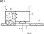
- the functional components can be directly or indirectly, ie with the interposition of at least one mounting member 17 (see. Fig. 4 ), on and / or in the process block 8.
- Fig. 4 shows a schematic diagram of a mounting situation of a functional component of the device 1 according to an embodiment.
- Fig. 4 is the case of an indirect attachment of a functional component, here by way of example a beam deflection device 7a as part of the exposure device 7 shown.
- the functional component is fastened to the process block 8 via a mounting component 17 fastened to the process block 8 or the process block main body 10.
- the functional component is fastened to the mounting component 17 in an invariably positionally stable arrangement and alignment, the mounting component 17 being fastened to the process block 8 in a fixed positionally fixed arrangement and orientation.
- the mounting member 17, which z. B. may be formed as a mounting block or as a mounting bracket has tight tolerances, so that the attached via this attached to the process block 8 functional component is exactly.
- the mounting component 17 comprises at least one first attachment interface 18, which is set up for fastening the functional component in a fixed positionally fixed positioning on the mounting component 17.
- the first attachment interface 18 enables a frictional attachment of the functional component to the assembly component 17.
- the first attachment interface 18 comprises a plurality of bores (not shown) that can be passed through by a screw element 19, in particular threaded bores.
- the assembly component 17 further comprises at least one second attachment interface 20, which is set up for fixing the assembly component 17 in a fixed positionally fixed positioning on the process block 8.
- the second attachment interface 20 allows in the embodiment, a frictional attachment of the mounting member 17 to the process block 8.
- the second attachment interface 20 includes a plurality of enforceable by a screw member 21 holes (not shown), in particular threaded holes.
Landscapes
- Engineering & Computer Science (AREA)
- Chemical & Material Sciences (AREA)
- Materials Engineering (AREA)
- Manufacturing & Machinery (AREA)
- Physics & Mathematics (AREA)
- Optics & Photonics (AREA)
- Mechanical Engineering (AREA)
- Analytical Chemistry (AREA)
- Automation & Control Theory (AREA)
- Plasma & Fusion (AREA)
- Ceramic Engineering (AREA)
- Inorganic Chemistry (AREA)
- Structural Engineering (AREA)
- Organic Chemistry (AREA)
- Powder Metallurgy (AREA)
- Producing Shaped Articles From Materials (AREA)
Applications Claiming Priority (1)
| Application Number | Priority Date | Filing Date | Title |
|---|---|---|---|
| DE102016121782.4A DE102016121782A1 (de) | 2016-11-14 | 2016-11-14 | Vorrichtung zur additiven Herstellung dreidimensionaler Objekte |
Publications (2)
| Publication Number | Publication Date |
|---|---|
| EP3321050A2 true EP3321050A2 (fr) | 2018-05-16 |
| EP3321050A3 EP3321050A3 (fr) | 2018-08-08 |
Family
ID=59298294
Family Applications (1)
| Application Number | Title | Priority Date | Filing Date |
|---|---|---|---|
| EP17179842.4A Withdrawn EP3321050A3 (fr) | 2016-11-14 | 2017-07-05 | Dispositif de fabrication par méthode additive d'objets tridimensionnels |
Country Status (5)
| Country | Link |
|---|---|
| US (1) | US20180133961A1 (fr) |
| EP (1) | EP3321050A3 (fr) |
| JP (1) | JP6590893B2 (fr) |
| CN (1) | CN108068327B (fr) |
| DE (1) | DE102016121782A1 (fr) |
Families Citing this family (2)
| Publication number | Priority date | Publication date | Assignee | Title |
|---|---|---|---|---|
| CN115697594B (zh) * | 2020-05-27 | 2025-05-30 | 速尔特技术有限公司 | 用于增材制造的打印盒 |
| EP3915700A1 (fr) * | 2020-05-28 | 2021-12-01 | Trumpf Sisma S.r.l. | Machine de fabrication de composants tridimensionnels |
Citations (2)
| Publication number | Priority date | Publication date | Assignee | Title |
|---|---|---|---|---|
| DE20101996U1 (de) * | 2001-02-06 | 2001-04-05 | itec Gesellschaft für Prozeßautomation und Meßtechnik mbH, 12526 Berlin | Vorrichtung zur Laserbearbeitung von Werkstücken |
| US20020090313A1 (en) * | 2000-11-27 | 2002-07-11 | Wang Xinhua | Method and apparatus for creating a free-form three-dimensional metal part using high-temperature direct laser melting |
Family Cites Families (24)
| Publication number | Priority date | Publication date | Assignee | Title |
|---|---|---|---|---|
| DE3446036A1 (de) * | 1984-12-18 | 1986-06-19 | Gebr. Hennig Gmbh, 8045 Ismaning | Kabine |
| US5184307A (en) * | 1988-04-18 | 1993-02-02 | 3D Systems, Inc. | Method and apparatus for production of high resolution three-dimensional objects by stereolithography |
| US5435902A (en) * | 1993-10-01 | 1995-07-25 | Andre, Sr.; Larry E. | Method of incremental object fabrication |
| US5976339A (en) * | 1993-10-01 | 1999-11-02 | Andre, Sr.; Larry Edward | Method of incremental layered object fabrication |
| DE19905067A1 (de) * | 1999-02-08 | 2000-08-10 | Matthias Fockele | Vorrichtung zur Herstellung eines Formkörpers durch schichtweises Aufbauen aus pulverförmigem, insbesondere metallischem Werkstoff |
| US6627376B1 (en) * | 1999-04-27 | 2003-09-30 | Teijin Seiki Co., Ltd. | Stereolithographic apparatus and method for manufacturing three-dimensional object with photohardenable resin |
| DE102007050953A1 (de) * | 2007-10-23 | 2009-04-30 | Voxeljet Technology Gmbh | Vorrichtung zum schichtweisen Aufbau von Modellen |
| US8826938B2 (en) * | 2008-01-22 | 2014-09-09 | Control Components, Inc. | Direct metal laser sintered flow control element |
| US7942987B2 (en) * | 2008-06-24 | 2011-05-17 | Stratasys, Inc. | System and method for building three-dimensional objects with metal-based alloys |
| US8678805B2 (en) * | 2008-12-22 | 2014-03-25 | Dsm Ip Assets Bv | System and method for layerwise production of a tangible object |
| US8278866B2 (en) * | 2009-02-03 | 2012-10-02 | Objet Ltd. | Method and apparatus for accurate positioning of printing units |
| WO2010095987A1 (fr) * | 2009-02-18 | 2010-08-26 | Arcam Ab | Appareil pour produire un objet tridimensionnel |
| DE102009036153A1 (de) * | 2009-08-05 | 2011-02-17 | Modellbau Robert Hofmann Gmbh | Vorrichtung zur generativen Herstellung dreidimensionaler Formteile |
| AU2010295585B2 (en) * | 2009-09-17 | 2015-10-08 | Sciaky, Inc. | Electron beam layer manufacturing |
| JP2011090055A (ja) * | 2009-10-20 | 2011-05-06 | Sony Corp | 露光装置及び露光方法 |
| DE102010050359B4 (de) * | 2010-11-05 | 2013-04-18 | Cl Schutzrechtsverwaltungs Gmbh | Vorrichtung zum Herstellen von dreidimensionalen Objekten |
| ES2728228T3 (es) * | 2011-04-15 | 2019-10-23 | MTU Aero Engines AG | Procedimiento para la fabricación de un componente con al menos un elemento de construcción dispuesto en el componente, así como un componente con al menos un elemento de construcción |
| DE102012009071A1 (de) * | 2012-05-09 | 2013-11-14 | Cl Schutzrechtsverwaltungs Gmbh | Vorrichtung zur Herstellung von dreidimensionalen Objekten mit Verstellvorrichtung |
| DE102012014839A1 (de) * | 2012-07-27 | 2014-01-30 | Cl Schutzrechtsverwaltungs Gmbh | Vorrichtung zur Herstellung dreidimensionaler Objekte |
| US9011136B1 (en) * | 2014-02-19 | 2015-04-21 | Massivit 3D Printing Technologies Ltd | Additive manufacturing device |
| DE102014221501A1 (de) * | 2014-10-23 | 2016-04-28 | MTU Aero Engines AG | Vorrichtung und Verfahren zur Herstellung oder Reparatur eines dreidimensionalen Objekts |
| US9481133B2 (en) * | 2014-12-31 | 2016-11-01 | Makerbot Industries, Llc | Passive z-axis alignment |
| CN204773600U (zh) * | 2015-06-03 | 2015-11-18 | 武汉映未三维科技有限公司 | 一种桌面式喷墨3d打印机 |
| CN105880590B (zh) * | 2016-04-19 | 2017-12-26 | 西安交通大学 | 一种可连续成型的增材制造系统 |
-
2016
- 2016-11-14 DE DE102016121782.4A patent/DE102016121782A1/de not_active Withdrawn
-
2017
- 2017-07-05 EP EP17179842.4A patent/EP3321050A3/fr not_active Withdrawn
- 2017-08-31 CN CN201710770169.9A patent/CN108068327B/zh not_active Expired - Fee Related
- 2017-11-08 JP JP2017215279A patent/JP6590893B2/ja not_active Expired - Fee Related
- 2017-11-14 US US15/812,668 patent/US20180133961A1/en not_active Abandoned
Patent Citations (2)
| Publication number | Priority date | Publication date | Assignee | Title |
|---|---|---|---|---|
| US20020090313A1 (en) * | 2000-11-27 | 2002-07-11 | Wang Xinhua | Method and apparatus for creating a free-form three-dimensional metal part using high-temperature direct laser melting |
| DE20101996U1 (de) * | 2001-02-06 | 2001-04-05 | itec Gesellschaft für Prozeßautomation und Meßtechnik mbH, 12526 Berlin | Vorrichtung zur Laserbearbeitung von Werkstücken |
Also Published As
| Publication number | Publication date |
|---|---|
| US20180133961A1 (en) | 2018-05-17 |
| CN108068327B (zh) | 2020-07-28 |
| EP3321050A3 (fr) | 2018-08-08 |
| JP6590893B2 (ja) | 2019-10-16 |
| CN108068327A (zh) | 2018-05-25 |
| JP2018080389A (ja) | 2018-05-24 |
| DE102016121782A1 (de) | 2018-05-17 |
Similar Documents
| Publication | Publication Date | Title |
|---|---|---|
| EP3377304B1 (fr) | Dispositif de fabrication additive d'un objet tridimensionnel | |
| EP3516859B1 (fr) | Système de caméra monté dans un boîtier, procédé et dispositif pour produire ledit système de caméra | |
| EP2359988B1 (fr) | Méthode pour calibrer un robot parallèle | |
| EP2693107B1 (fr) | Unité optique primaire pour un module d'éclairage | |
| DE102013103791B4 (de) | Monolithisches Wägesystem | |
| DE102014207457A1 (de) | Anordnung, Prüfstand und Verfahren zur Prüfung eines Weichenantriebs | |
| EP3321065A1 (fr) | Dispositif de fabrication additive d'objets tridimensionnels | |
| EP3426425B1 (fr) | Dispositif pour la fabrication additive d'un objet tridimensionnel | |
| EP3321050A2 (fr) | Dispositif de fabrication par méthode additive d'objets tridimensionnels | |
| EP3311983A1 (fr) | Dispositif et procede de fabrication additive d'objets tridimensionnels | |
| WO2021255600A1 (fr) | Boîtier électronique de contrôle moteur ayant une précision d'angle de rotation améliorée | |
| DE102014213888A1 (de) | Justiervorrichtung und Justierverfahren | |
| DE102016122977A1 (de) | Bedienvorrichtung mit mehreren Bedienbaugruppen und haptischen Feedback sowie Verfahren zur Herstellung der Bedienvorrichtung | |
| DE102007060606B4 (de) | Koordinatenmessgerät mit Kompensation von thermisch bedingten Längenänderungen für die Koordinatenbestimmung | |
| EP3756797B1 (fr) | Procédé d'essai de nouvelles compositions de materiaux pour la fusion laser sur lit de poudre, et dispositif conçu a cet effet | |
| EP1639690B1 (fr) | Mecanisme d'entrainement direct plan comprenant un systeme de mesure de position | |
| WO2020225263A1 (fr) | Tête d'usinage pour guider un faisceau laser et dispositif d'usinage au laser comprenant une tête d'usinage | |
| EP3921608B1 (fr) | Système de mesure gravimétrique | |
| WO2015090652A1 (fr) | Dispositif de positionnement | |
| DE102021129526B4 (de) | Taktiles Rauheitsmesssystem | |
| DE102008036574A1 (de) | Vorrichtung zum Lagern eines optischen Elements | |
| DE102016122978A1 (de) | Verfahren und Anordnung zur Herstellung einer Bedienvorrichtung mit haptischem Feedback | |
| DE102013211101A1 (de) | Vorrichtung zum Ausgleich von Positionsungenauigkeiten zwischen zwei Fügepartnern entlang einer Achse, Fügevorrichtung und Produktionsanlage | |
| WO2024184049A1 (fr) | Unité d'affichage pour un dispositif d'automatisation de terrain | |
| DE102004061432B4 (de) | Positioniervorrichtung |
Legal Events
| Date | Code | Title | Description |
|---|---|---|---|
| PUAI | Public reference made under article 153(3) epc to a published international application that has entered the european phase |
Free format text: ORIGINAL CODE: 0009012 |
|
| STAA | Information on the status of an ep patent application or granted ep patent |
Free format text: STATUS: THE APPLICATION HAS BEEN PUBLISHED |
|
| AK | Designated contracting states |
Kind code of ref document: A2 Designated state(s): AL AT BE BG CH CY CZ DE DK EE ES FI FR GB GR HR HU IE IS IT LI LT LU LV MC MK MT NL NO PL PT RO RS SE SI SK SM TR |
|
| AX | Request for extension of the european patent |
Extension state: BA ME |
|
| PUAL | Search report despatched |
Free format text: ORIGINAL CODE: 0009013 |
|
| AK | Designated contracting states |
Kind code of ref document: A3 Designated state(s): AL AT BE BG CH CY CZ DE DK EE ES FI FR GB GR HR HU IE IS IT LI LT LU LV MC MK MT NL NO PL PT RO RS SE SI SK SM TR |
|
| AX | Request for extension of the european patent |
Extension state: BA ME |
|
| RIC1 | Information provided on ipc code assigned before grant |
Ipc: B33Y 30/00 20150101ALI20180703BHEP Ipc: B28B 1/00 20060101AFI20180703BHEP Ipc: B29C 64/20 20170101ALI20180703BHEP Ipc: B33Y 10/00 20150101ALI20180703BHEP Ipc: B22F 3/105 20060101ALI20180703BHEP Ipc: B29C 64/153 20170101ALI20180703BHEP Ipc: B29C 64/25 20170101ALI20180703BHEP |
|
| STAA | Information on the status of an ep patent application or granted ep patent |
Free format text: STATUS: REQUEST FOR EXAMINATION WAS MADE |
|
| 17P | Request for examination filed |
Effective date: 20190208 |
|
| RBV | Designated contracting states (corrected) |
Designated state(s): AL AT BE BG CH CY CZ DE DK EE ES FI FR GB GR HR HU IE IS IT LI LT LU LV MC MK MT NL NO PL PT RO RS SE SI SK SM TR |
|
| STAA | Information on the status of an ep patent application or granted ep patent |
Free format text: STATUS: EXAMINATION IS IN PROGRESS |
|
| 17Q | First examination report despatched |
Effective date: 20210616 |
|
| GRAP | Despatch of communication of intention to grant a patent |
Free format text: ORIGINAL CODE: EPIDOSNIGR1 |
|
| STAA | Information on the status of an ep patent application or granted ep patent |
Free format text: STATUS: GRANT OF PATENT IS INTENDED |
|
| RIC1 | Information provided on ipc code assigned before grant |
Ipc: B33Y 30/00 20150101ALI20220112BHEP Ipc: B29C 64/25 20170101ALI20220112BHEP Ipc: B29C 64/153 20170101ALI20220112BHEP Ipc: B22F 12/00 20210101ALI20220112BHEP Ipc: B22F 10/28 20210101AFI20220112BHEP |
|
| INTG | Intention to grant announced |
Effective date: 20220216 |
|
| STAA | Information on the status of an ep patent application or granted ep patent |
Free format text: STATUS: THE APPLICATION IS DEEMED TO BE WITHDRAWN |
|
| 18D | Application deemed to be withdrawn |
Effective date: 20220628 |